1
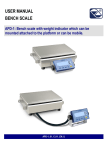
WEIGHT INDICATOR WITH
WHEEL WEIGHING FUNCTION
DFWKR
USER MANUAL
DFWKR_03_10.08_EN_U
DFWKR
INDEX
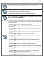
1. INTRODUCTION.................................................................................................................................................................2
2. MAIN TECHNICAL SPECIFICATIONS...............................................................................................................................4
3. SYMBOLS...........................................................................................................................................................................4
4. DIMENSIONS......................................................................................................................................................................5
5. POWER SUPPLY & START UP .........................................................................................................................................6
6. FRONT PANEL KEYS AND INDICATORS ........................................................................................................................7
7. LCD DISPLAY SYMBOLS................................................................................................................................................10
8. BASIC INSTRUMENT FUNCTIONS .................................................................................................................................11
8.1 ZERO SCALE FUNCTIONS .......................................................................................................................................11
8.1.1 OPERATION OF ZERO ON THE SINGLE SCALE ..............................................................................................11
8.1.2 CYCLE OF ZERO ON ALL THE CONNECTED SCALES....................................................................................11
8.2 TARE OPERATIONS..................................................................................................................................................12
8.3 DISPLAY WITH SENSITIVITY X 10 ...........................................................................................................................14
8.4 DISPLAY OF METRIC DATA (inFO) ..........................................................................................................................14
8.5 AUTOMATIC SWITCH-OFF FUNCTION....................................................................................................................14
8.6 BATTERY LEVEL WARNING .....................................................................................................................................15
8.7 FUNCTIONING WITH REMOTE CONTROL ..............................................................................................................15
8.8 DATE/TIME ADJUSTMENT (OPTIONAL) ..................................................................................................................16
8.9 EXECUTION OF THE PRINTOUTS ...........................................................................................................................16
8.10 PRINTING OF THE HEADING .................................................................................................................................18
8.11 TICKET NUMBER.....................................................................................................................................................18
8.12 REPETITION OF THE LAST PRINTOUT MADE......................................................................................................18
8.13 REENABLING THE PRINTOUTS AND THE INDICATOR FUNCTIONS ..................................................................18
8.14 LOCK / UNLOCK KEYBOARD .................................................................................................................................18
8.15 IDENTIFICATION CODES........................................................................................................................................19
8.16 kg lb SWITCH FUNCTION.............................................................................................................................19
8.17 NET GROSS SWITCH...................................................................................................................................20
9. WEIGHING OPERATIONS ...............................................................................................................................................21
9.1 MODIFICATION OF THE DISPLAYED DATA ............................................................................................................21
9.2 ENTRY OF VEHICLE WHEELS NUMBER FOR AUTOMATIC PRINTING OF VEHICLE TOTAL..............................21
9.3 PRINTING OF THE SUBTOTALS ..............................................................................................................................22
9.4 QUICK SETTING OF INSTRUMENT’S NUMBER OF SCALES .................................................................................22
9.5 DISPLAY OF DATA OF WEIGH UNDER WAY (ONLY FOR TOTALIZER MODES) ..................................................23
9.6 DISPLAY OF WEIGHED VEHICLES NUMBER AND RELATIVE TOTAL WEIGHT ...................................................23
9.7 CANCELLING THE WEIGH AND ZEROING THE VEHICLE TOTAL OR VEHICLES TOTAL....................................24
9.8 ENTRY OF COORDINATES FOR CALCULATING THE BARYCENTRE ( OR CENTRE OF GRAVITY)...................24
9.9 QUICK FORMATTING OF THE WEIGHT DATA PRINTING ......................................................................................25
10. WHEEL WEIGHING APPLICATIONS ............................................................................................................................26
10.1 SIMPLE WHEELS/AXLES WEIGHING.....................................................................................................................26
10.2 WEIGHING WITH AXLE TOTALISATION ................................................................................................................26
10.3 SIMPLE INPUT/OUTPUT FUNCTIONING MODE....................................................................................................27
10.4 INPUT/OUTPUT FUNCTIONING MODE WITH AXLE TOTALISATION...................................................................28
11. INSTRUMENT CONNECTED TO BATTERY OPERATED PRINTER ............................................................................29
12. TURNING ON PRINTER IN ENERGY SAVING MODE ..................................................................................................29
13. INSTRUMENT MESSAGES DURING USE ....................................................................................................................30
DECLARATION OF CONFORMITY .....................................................................................................................................31
WARRANTY .........................................................................................................................................................................31
1
DFWKR
1. INTRODUCTION
This indicator allows to:
- quickly view the sum of all the scales, the single scales and the possible combinations (scales 1 + 2, scales
1 + 3 + 4…)
- totalize the weight of the axles, obtaining in this way the total weight of the tractor-trailers or the tractor with the trailer.
- enter the scales’ coordinates in order to obtain the calculation and printout of the vehicle’s barycentre coordinates.
- print the displayed weight, the total weight of a vehicle or the number of weighed vehicles with relative total.
- print the subtotal of the tractor and of the trailer in the weighing of composite vehicles (like tractor + trailer).
There are two total levels, vehicle total and vehicles total, quickly visible by the user and manually zeroable.
WARNING
Any attempt to repair or alter the unit can expose the user to the danger of electric shock and it will void our warranty. This
instrument is covered under warranty provided that IT HAS NOT BEEN OPENED BY THE USER for any reason. If any
problem with the unit or system has been experienced please notify the manufacturer or the dealer from which the
instrument was acquired.
The 6V rechargeable battery has to be completely recharged (12 hours) in the first installation of the instrument;
we RECOMMEND disconnecting the battery if the instrument is not going to be used for more than 30 days.
In order to avoid the deterioration of the rechargeable battery:
In standard conditions:
- never leave the battery partially or completely uncharged; at least once a week recharge it completely .
In case the instrument is not used for a long period, one needs to:
- completely recharge the battery before the system is switched off for the last time.
- recharge completely every 3 months.
Do not pour liquids on the indicator!!
Do not use solvents to clean the indicator
Do not expose instrument to either direct sun light or any heat sources
Always mount the indicator and platform in a vibration free setting!!
READ CAREFULLY & APPLY WHAT DESCRIBED IN THE POWER SUPPLY & START-UP SECTION!
Do not install in an environment with any risk of explosion!
All the connections of the indicator have to be made respecting the rules applicable in the zone and in the
installing environment
Everything not expressly described in this manual has to be considered as improper use of the equipment.
!! IMPORTANT !!
To maintain a data coherence one should respect the numbering of the connections (in other words, channel 1 with scale 1,
channel 2 with scale 2…)
2
DFWKR
The symbol of the crossed trash can on the equipment shows that the product at the end of its utility
must be handled separately from other trash. Therefore, when the product is no longer used, the user
should take it to the appropriate places in which electronic and electrotechnical trash is taken or he may
take it to the reseller when he purchases a new equivalent type of equipment. The adequate
differentiated refuse collection in having the instrument recycled, treated and disposed of in an
environmentally friendly manner helps to avoid possible negative effects on the environment and health
and supports the recycling of the materials of which the equipment is made. The unlawful disposal of
the product by the user will entail fines foreseen by the current regulations.
Norm references: 2002/95/CE, 2002/96/CE and 2003/108/CE community directives and law 151 of 25/7/05.
NOTE FOR THE USER:
Please take note that when the “step…. (TECH.MAN.REF.)” Is mentioned, this refers to the technical manual which
may be obtained from the reseller.
3
DFWKR
2. MAIN TECHNICAL SPECIFICATIONS
POWER SUPPLY
MAXIMUM POWER
OPERATING TEMPERATURE
DISPLAYED DIVISIONS
230Vac +10% ÷ -15%, 50-60Hz with external wall adapter providing 12Vdc
(included)
or fitted rechargeable internal (6 Vs – 4,5 Ah) battery.
5 VA
From -10 to +40 °C (with even temperature).
10000e, 3X3000e for legal for trade use expandable to 100.000 for internal factory
use.
MAXIMUM INPUT SIGNAL
MINIMUM VOLTAGE PER DIVISION
RESOLUTION IN CALCULATION
6 mV/V.
0.3 µV (approved instrument); 0.03 µV (non approved instrument).
150000 points.
KEYBOARD
TARE FUNCTION
water resistant polycarbonate membrane keys with tactile and acoustic feedback.
Subtractive possible on all capacities.
If set, it is subtracted when printing the accumulated total.
programmable
" Low.batt " will appear on display when battery is near depletion
( max. 40 hours with 1 load cell).
12 hours
5Vdc ± 5%, 120mA (max 8 cells of 350 Ohms)
4 wires with Remote Sense
1 RS232/TTL input/output configurable for connection to PC/PLC or WEIGHT
REPEATER.
1 RS232 input/output for connection to printer.
AUTO POWER OFF
LOW BATTERY WARNING
BATTERY RECHARGE TIME
LOAD CELL POWER SUPPLY
LOAD CELL CONNECTIONS
SERIAL OUTPUTS
THE PARTS OF THE INSTRUMENT CONTAINING DANGEROUS ELECTRICAL TENSION ARE ISOLATED AND
INACCESSIBLE TO THE USER UNLESS IT HAS BEEN DAMAGED, OPENED, OR ALTERED.
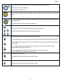
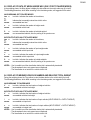
3. SYMBOLS
To call the attention of the user, the following symbols are used both in the manual and on the instrument itself:
!! WARNING !!
THIS OPERATION MUST BE PERFORMED ONLY BY QUALIFIED PERSONAL
CONFORMS TO THE STANDARDS OF THE EUROPEAN UNION.
IDENTIFIES THE CLASS OF PRECISION DEFINED BY THE OIML TO
REPRESENT 3000 DIVISIONS
XXXX
…
ZZZZ
Indicates the path that needs to be followed (except possible approval conditions for which some
parameters are not accessible) in order to reach the step in which one sets that parameter, inside
the SET-UP or a menu.
4
DFWKR
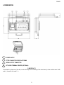
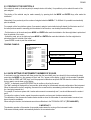
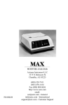
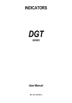
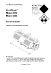
4. DIMENSIONS
1
POWER SUPPLY
2
FITTED CONNECTORS FOR PLATFORMS
3
SERIAL OUTPUT CONNECTOR
4
ATTACHED THERMAL PRINTER (OPTIONAL)
!! IMPORTANT !!
To maintain the coherence of the data, one should respect the numbering of the connections (in other words channel 1 with
scale 1, channel 2 with scale 2…).
5
DFWKR
5. POWER SUPPLY & START UP
The instruments are powered with a rechargeable built-in battery.
It is also possible to power through a 12 Vdc tension supplied from an AC/DC external charger (supplied) which should be
connected to the 230 Vac mains voltage. Safety norms must be respected for the connection to the mains voltage including
the use of a line which has to be free from noise generated by other electronic equipment.
If the instrument is correctly powered, the power on led turns on in the front panel (see section 6).
The battery lifetime is about 40 hours when the instrument is connected to 1 load cell, and 24 hours if it is connected to 4
load cells.
To completely recharge the battery, connect the AC/DC power adapter for 12 hours.
BATTERY CHARACTERISTICS
Material Lead
Power 4,5 Ah
Output 6 V
THE BATTERY MUST ONLY BE REPLACED WITH AN ORIGINAL FROM THE MANUFACTURER.
Do not connect other equipment to the same socket as the one that the adapter is in.
Do not step on or crush the power supply cable
TO TURN ON the instrument press the C key until the indicator turns on; then release.
The display shows:
XX.YY
it’s the installed software version
bt XXX
in which XXX is a number from 0 to 100 which indicates the battery level.
The indicator is fitted with an “automatic zero at start-up” function: this means that when turned on if a weight is detected
which is within +/- 10% of the capacity; it is cleared; if the weight is not within this tolerance, while with non approved
instrument, after a few instants the display shows the sum of the weights.
With approved instrument, instead, “ZErO” is continuously shown on the display, until the weight re-enters within the
tolerance; the automatic zero function at start-up may be disabled in the set-up environment (only with non approved
instrument) (TECH.MAN.REF.).
By pressing the ZERO key for an instant while the version is shown on the display, the indicator shows in sequence:
CLoCk
the indicator detects automatically that the optional board with date and time is connected.
02.01
in which 02 indicates the instrument type, 01 indicates the metrological software version.
XX.YY.ZZ installed software version
dFWKr
software name
bt XXX
in which XXX is a number from 0 to 100 which indicates the battery level.
-K- X.YY in which K identifies the type of keyboard: K=17-key keyboard.
X.YY is the installed software version.
nCh x
in which x represents the number of channels set in the TECHNICAL SET-UP nChAn
(TECH.MAN.REF.).
PPP.PPP capacity and division of the scale relative to channel 1.
Subsequently the instrument shows “hi rES” (in case of non legal for trade instrument) or “LEGAL” and the G gravity value
(if legal for trade instrument is used), and then a countdown is made (self check phase).
TO TURN OFF the instrument keep C pressed until the - oFF – message appears on the display.
6
DFWKR
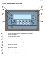
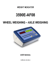
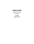
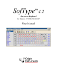
6. FRONT PANEL KEYS AND INDICATORS
1
5
2
6
3
7
4
8
1
Indicates that the weight detected by the weighing system is close to zero,
within ±1/4 of the division.
2
Indicates that the weight is unstable.
3
Indicates the presence of the power supply.
4
Indicates that the displayed value is a net weight.
5
Not used in the application.
6
Not used in the application.
7
Sensor for the reception of the infrared signal (optional).
8
Indicates that a specific function of the indicator is active.
7
DFWKR
KEY
DESCRIPTION
Zeros the gross weight displayed on the single scale if it’s within +/- 2% of the total capacity.
Depending on the type of tare selected (F.ModE >> tArE.t parameter, TECH.MAN.REF.):
- Tares the displayed weight, switching the display on the net weight.
- Accumulates the weight displayed in the tare total, not switching the current display.
Allows to totalize the weight on the weighing system (the ~ led should be turned off), with subsequent
printing of the formatted data (TECH.MAN.REF.).
- If pressed at length while the weight on the single scale is displayed it allows to pass to the weight
display with sensitivity X 10.
- If pressed briefly it allows to carry out the secondary function of the keys:
- By pressing the MODE and F keys one quickly accesses to the configuration menu of the printouts
(TECH.MAN.REF.).
- By pressing the MODE and ZERO keys, one carries out the cycle of zero on all the connected scales
(see section 8.1.2).
- By pressing the MODE and TARE keys, one enters a tare total value in the input/output mode (see
section 10.3).
- By pressing the MODE and PRINT keys, one prints the subtotal (see section 9.3).
- By pressing the MODE and MODE keys, one selects the number of scales which one wants to use
(see section 9.4).
- By pressing the MODE and 0 keys, one locks/unlocks the keyboard.
- By pressing the MODE and 1 keys one selects a tare value in the tare database (see section 8.2).
- By pressing the MODE and 2 keys one switches between the locked and unlocked tare (see section
8.2).
- By pressing the MODE and 3 keys one sets the numeric ID values (see section 8.15).
- By pressing the MODE and 4 keys, one switches between the locked ID and unlocked ID function (see
section 8.15).
- By pressing the MODE and 6 keys, it is possible to switch the weight between kilograms and pounds
(see section 8.16).
- By pressing the MODE and 7 keys, one enters in the menu for entering the number of wheels for
automatic printing of the vehicle total or subtotals (see section 9.2).
- By pressing the MODE and 9 keys, one enters the values in the tare database (see section 8.2).
- By pressing the MODE and i keys (info key), the last printout made will be repeated.
8
DFWKR
- Prints and clears the accumulated total, incrementing the total of weighed vehicles.
- Ends an input or output totalisation.
- Confirms the changes made.
Allows viewing the scale’s metric information: capacity, division, minimum weigh for each configured
scale.
- If pressed briefly it allows to cancel the weigh under way and/or the total tare value entered for the
input/output mode.
- If pressed at length it turns on and off the instrument.
- Allow to switch the weight display between each scale (see section 9.1).
- Numeric keyboard function while entering the numeric values.
- Numeric keyboard function while entering the numeric values.
- In the weighing status by pressing the 5 key one enters the coordinates for calculating the barycentre.
- In the weighing status, press the 6 key: the data relative to the weigh under way will be displayed (see
section 9.5).
- In the weighing status by pressing the 7 key, the data relative to the vehicles weighed until that
moment will be displayed (see section 9.6).
- In the weighing status, by pressing the 7 key at length, one zeros the number of
vehicles weighed until that moment (see section 9.7).
- Acquires the weigh in input.
- Numeric key functions during the entry of numeric values.
- Acquires the output weigh.
- Numeric key function during the entry of numeric values.
9
DFWKR
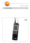
7. LCD DISPLAY SYMBOLS
The LCD display has symbols which, during the weighing phase, give the indication of the indicator’ functioning status;
below is the description for each symbol.
FIGURE 5 – LCD DISPLAY
NUMBER
(1)
SYMBOL
0
(2)
~
The weight is unstable.
The time is being displayed in the “HH:MM:SS”.
(3)
(4)
(5)
NET
G
(6)
B
(7)
(8)
FUNCTION
The weight detected by the weighing system is near zero, within –1/4 ÷ +1/4 of the
division.
The displayed weight is a net weight.
The displayed weight is a gross weight, if the Italian or English is in the print
configuration.
The displayed value is a gross weight, if the German, French or Spanish language is
selected in the print configuration.
Indicates the battery charge level: see section 8.6 - “BATTERY LEVEL WARNING”.
MAX=
When the metric information is displayed, it identifies the indicated range capacity.
MIN=
When the metric information is displayed, it identifies the minimum weight of the
indicated range.
(9)
e=
LT
When the metric information is displayed, it identifies the indicated range division.
A locked tare is active.
(10)
PT
A manual tare is active.
(11)
W1
W2
Not used in the application.
W3
10
DFWKR
(12)
Indicates the scales that are being shown.
(13)
PCS
Not used in the application.
(14)
kg
Indicates the unit of measure in use (“kg” for kilograms, “g” for grams).
(15)
%
Not used in the application.
(16)
t
Indicates the unit of measure in use (tons).
(17)
LB
Indicates the unit of measure in use (pounds).
(18)
They are displayed around the digits having the greatest sensitivity, when the weight
x 10 display function is active.
(19)
*
Indicates that a key has been pressed .
(20)
(21)
(22)
PEAK
HOLD
SP1
Not used in the application.
Not used in the application.
SP2
Not used in the application.
SP3
SP4
8. BASIC INSTRUMENT FUNCTIONS
8.1 ZERO SCALE FUNCTIONS
8.1.1 OPERATION OF ZERO ON THE SINGLE SCALE
- Select the scale using the numerical keyboard, using the keys 1, 2, 3, 4;
- Press the ZERO key; the message "Zero" appears on the display for a few instants and the weight on the
scale, if within ±2% of the maximum capacity, is zeroed. If the weight is not within this range, the message
"ZEro" remains until the indicator tries to carry out the zero scale; then an error sound is emitted; one
automatically returns to the display of the weight present on the scale.
8.1.2 CYCLE OF ZERO ON ALL THE CONNECTED SCALES
Go to the sum of weights display mode, press the combination of the MODE and ZERO keys, the weight on the
scales, if within ±2% of them maximum capacity, is zeroed.
The message "ZEro" appears on the display, followed by the number of the scale being zeroed (for example "ZEro 1"
for scale 1, "ZEro 2" for scale 2…).
NOTE: the cycle of zero pertains only to displayed scales.
11
DFWKR
8.2 TARE OPERATIONS
PREMISE: in order to carry out tare functions the instrument should display the sum of the weights.
Depending on the type of tare selected in the TECHNICAL SET-UP >> F.ModE >> tArE.t (TECH.MAN.REF.), the tare
function is managed in the following way:
A) tArE.t = t.norM : SUBTRACTION OF THE TARE FROM DISPLAYED WEIGHT FUNCTION
SEMI-AUTOMATIC TARE
By pressing the TARE key any weight value present on the display is tared: the display shows “tArE” for an instant and
then 0 (net weight); the relative keys turn on.
NOTE: The semiautomatic tare will be acquired only if the weight is AT LEAST A DIVISION, STABLE (instability ~ led
off) and VALID (in other words, the OVERLOAD condition should not be created).
ENTERING THE MANUAL TARE FROM KEYBOARD
1. - Press TARE for a few seconds: the display shows “– tM –“ and then "000000". Enter the desired value.
- Confirm with the ENTER key; the value will be subtracted from the weight present on the plate and the relative
pilot lights will turn on.
2. - press the numeric 0 key
- digit the desired value through the numeric keys (press “i” to enter the decimal point)
- confirm with TARE key
If the entered value is not a multiple of the scale’s minimum division, it will be rounded off.
CANCELLING A TARE
One can manually cancel the tare value in different ways:
- unload the scale and press the TARE or ZERO key.
- carry out the tares in deduction, partially unloading the scale and pressing TARE to zero the display.
- press C without unloading the scale; the “CltAr?” message appears on the display: press ENTER to cancel the tare
and press C to exit without saving the changes.
- enter a manual tare equal to 0.
DISABLED TARE SELECTION
It is possible to disable the tare functions; in order to do it, refer to the technical manual (TECH.MAN.REF.).
STORED TARE DATABASE
It’s possible to store up to 30 tare memory values, identified by the location numbers 1 to 30, which the user can recall
when needed. To insert a tare value press the MODE and 9 keys in sequence - the display will indicate "t nn", in which
nn is the number of the storage in which the value is memorized.
The selected value will substitute the accumulated tare total until that moment.
Press "01" then ENTER; the display will indicate "t00000" or any value that already exists in the "01" tare memory
location. Insert the desired value through the numeric keyboard (or modify the existing one) and press ENTER. Repeat
this sequence until the memory contains all the tare values desired by the user.
The value must be entered with the same unit of measure and with minimum division of the divisions of the
connected scales.
By pressing “C” the inserted value is quickly zeroed.
RECALL OF STORED TARE VALUES
To recall a stored value press the MODE and 1 keys in sequence. The display will indicate "t nn" in which nn is the
number of the storage in which the value is memorized.
By pressing now the numeric keys corresponding to the desired numeric position (01-30) and ENTER, the memorized
value will be subtracted in the printing phase, from the vehicle total.
In the APPROVED version, it is NOT possible to recall a tare from the database with a loaded scale or if there is a
SEMIAUTOMATIC tare.
12
DFWKR
NOTES:
- The value of the maximum tare enterable in the database is 999999
- The maximum tare value in the database which may be enabled is equal to the sum of the capacities of the channels
set in the SEtuP >> ConFiG >> nChAn, step (TECH.MAN.REF.).
B) tArE.t = t.tot SUBTRACTION OF THE TARE FROM DISPLAYED WEIGHT FUNCTION
To be used in the applications in which, in the axle totalisation weighing, one wants to tare the vehicle weight, load the
vehicle and weigh it again loaded, obtaining (by difference) the weight of the material loaded.
ACCUMULATION OF THE WEIGHT IN THE TARE TOTAL
The instrument is fitted with a tare total, which is accumulated with each pressing of the TARE key;
The reenabling of the weight accumulation function in the tare total depends on the condition set in the “reACt” step
(TECH.MAN.REF.).
The tare total is subtracted, in the printing phase, from the total weight of the weighed vehicle.
It is possible:
- to momentarily view the tare total on the display
- cancel the accumulated tare total by pressing the C key; the message "CL.tAr ?" is displayed: by pressing ENTER the
tare total is cancelled; by pressing C one returns to the weighing environment without making modifications to the total.
IMPORTANT: the weight shown on the display is always the GROSS.
MANUAL ENTRY OF THE TARE TOTAL
It is also possible to enter a tare value or modify the accumulated tare total by pressing the TARE key at length; the
display shows the message – tM – , followed by the stored tare total; enter the tare value using the numeric keyboard
and press the ENTER key to confirm. The C key allows to exit without saving any changes made.
With approved instrument, in order to accumulate the weight in the tare total, there must be at least 20 minimum
divisions on each connected scale (20e).
LOCKED / UNLOCKED / DISABLED TARE TOTAL SELECTION
Normally, when a tare value has been accumulated (automatic, manual or from storage), the value remains stored also
after the printing of the vehicle total (LOCKED TARE); therefore it remains active also for the following weighs.
It is possible to choose that the tare value cancels itself automatically with each vehicle total printout (UNLOCKED
TARE):
the accumulated tare total is automatically reset following the printing of the vehicle total (in other words the prolonged
pressure of the ENTER key following the totalisation of some weighs). Otherwise, with locked tare (combination of the
MODE and 2 keys ta – L), the tare total remains active until it is substituted by another value, or it is manually zeroed.
The selection can be made while weighing: if the tare has not been disabled, by pressing in sequence the
MODE and 2 keys: the display shows "tA - L", in other words the LOCKED TARE is selected; by pressing again the
same keys the display shows "tA - U", in other words UNLOCKED TARE is selected.
The indicator keeps the last selection made.
The selection made causes the modification and the automatic saving of the data in the TECHNICAL SET-UP.
It is possible to DISABLE the tare function of the indicator, by selecting in the TECHNICAL SET-UP >> F.ModE >> tArE
>> diSAb (TECH.MAN.REF.). In this way no tare operation can be made.
To restore the tare functions one should enter in the TECHNICAL SET-UP >> F.ModE >> tArE and select "LoCk"
(locked) or "unLoCk" (unlocked). (TECH.MAN.REF.).
NOTE: The turning off of the instrument causes the loss of the accumulated value.
Also with the tare total it is possible to use the tare database, entering, however, directly the total value.
13
DFWKR
8.3 DISPLAY WITH SENSITIVITY X 10
By pressing at length the MODE key during the weight display on the single scale, one switches between the weight display
with normal sensitivity and a sensitivity ten times greater; one will notice in fact that the last digit on the right of the display
will have a sensitivity equal to the scale division divided by 10.
The weight digits having greater sensitivity will have the symbol
.
To exit the display of the weight with sensitivity times 10, press the "C" key.
NOTES: In this condition:
- it’s not possible to carry out any weigh acquisition or printing function.
- it is possible to switch only to the weight display of the single scales.
- With an approved instrument, the viewing with sensitivity X 10 remains displayed for only 5 sec.; once this time has
passed one returns to the normal weighing status.
8.4 DISPLAY OF METRIC DATA (inFO)
The indicator is fitted with a function named “INFO”, thanks to which it is possible to view the configuration metric data:
- First range capacity, first range minimum weigh, first range division.
NOTES:
- The minimum weigh corresponds to 20 net weight divisions.
- The data of the second and third range appear only if actually configured.
To view the metric data:
-
-
Press the
key once.
The capacity value of the first range will appear.
Press the ZERO key to scroll the following data, in this order:
Capacity 1° range Minimum weigh 1° range Division 1° range
Capacity 1° range ………
Press the MODE key to change scale.
Press the TARE key to scroll backwards the metric data.
Press the ENTER/PRINT or C key to return to weighing.
8.5 AUTOMATIC SWITCH-OFF FUNCTION
A special circuit automatically turns off the scale if it has not been used for the programmed time period set in the
AutoFF parameter of the TECHNICAL SET-UP (TECH.MAN.REF.).
The AUTO POWER OFF function will not activate if a load is on the scale.
14
DFWKR
8.6 BATTERY LEVEL WARNING
The indicator is able to recognize whether it is powered from the mains or through a battery
If the indicator has the LCD display the charge level is shown in the weighing phase by the battery symbol:
-
: battery is charged.
-
: battery is partially charged.
: battery is discharged: connect the indicator to the mains for the recharging. Furthermore, for a few seconds the
"Low.bat " message appears on the display (voltage under 5,9 V).
RECHARGING PHASE:
…
RECHARGE IS COMPLETED:
NOTES:
- While recharging, the instrument can be used as usual.
- The instrument automatically turns off when the voltage goes below 5,8V.
- It’’s possible to view the recharge percentile of the battery by pressing the ZERO key upon start-up (see section 5 –
“POWER SUPPLY AND START-UP”).
8.7 FUNCTIONING WITH REMOTE CONTROL
NOTE: indoor use only.
With the remote control it is possible to remotely use various scale functions.
To choose which type of functioning follow the below procedure:
- Turn on the scale; press the TARE key while the firmware version is displayed (the display shows the “F.ModE” menu).
- Press ENTER/PRINT to enter the menu.
- Press ZERO many times (to scroll forwards through the parameters) or TARE (to scroll backwards) until one finds the
“irConF” parameter.
- Press ENTER/PRINT to enter the parameter.
- With the ZERO or TARE keys select the possible options: “ir no” (disabled remote control), “ir 1” (all the remote control
keys function as the TARE key) or “ir 4” (the remote control keys functions as ZERO, TARE, MODE and
ENTER/PRINT).
- Confirm with ENTER/PRINT.
- Press the C key many times until the message “SAVE?” appears on the display.
Press ENTER/PRINT to confirm the changes made or another key to not save.
In the “multifunction” configuration, the remote control keys repeat the keys’ functions (both the ones obtained with a
SHORT pressing as well as those with a LONG pressing) and they correspond to the following indicator keys:
REMOTE CONTROL KEY
FUNCTION
ZERO
Cycle of zero on all the connected scales
TARE
Weight accumulation in the tare total
F1/MODE
Totalisation
F2/PRINT
Printing of the total or simple printing (if total = 0)
Furthermore, by pressing at length the ZERO key, it’s possible to put the instrument in stand-by; by pressing any other key
one returns to the weighing mode.
15
DFWKR
8.8 DATE/TIME ADJUSTMENT (OPTIONAL)
The indicator can be fitted with the date/time option; in this case, the “CLoCk” message is shown when instrument is turned
on.
To set the date/time follow the procedure below:
- Press the MODE and then the 8 key: in this order one will be asked to enter the day, month, year, hour, and minutes.
The entry of each parameter must be confirmed with ENTER/PRINT.
- Press the C key many times until the message “SAVE?” appears on the display.
- Press ENTER/PRINT to confirm the changes made or another key to not save.
NOTES
- If there is no date/time option the pressure of MoDE and then 8 has no effect.
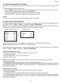
8.9 EXECUTION OF THE PRINTOUTS
If a printer is connected, each time the F key is pressed, it is possible to print the weight data programmed in the
TECHNICAL SET-UP >> SEtuP >> SEriAL >> Pr.ConF >> PForM (TECH.MAN.REF.).
Furthermore, if no totalisation has been made (therefore the total is at zero), with each pressure of the ENTER key, the
following printouts are made (extended with date/time, 4 heading lines and ticket number):
SUM OF VARIOUS SCALES
WHEEL 1
WHEEL 2
WHEEL 3
WHEEL 4
200kg
200kg
200kg
200kg
GROSS
TARE
NET
800kg
0kg
800kg
SINGLE SCALE
WHEEL 1
GROSS
TARE
NET
800kg
0kg
800kg
If one enters a manual tare or from the database, it will be indicated as PT (PRESET TARE) in the printout.
NOTE: the weight data printed with the PRINT key is not programmable.
It is possible to select the language of the printouts: Italian, English, German, French and Spanish (in the TECHNICAL
SET-UP >> SEtuP >> SEriAL >> Pr.ConF >> LAnG). (TECH.MAN.REF.)
Printing with NON approved scales.
In order to print with non approved scales the following conditions must exist:
- the weight must be stable;
- the gross weight must be >= 0 for each connected scale;
- the printout is always active.
NOTE: To print the weight totalised in the axle totalisation or input/output modes, the following must take place:
- the weight must be stable;
- the gross weight must be >= of a division and for each connected scale must be >= 0;
- The printing is reactivated depending on how the “rEACT” parameter has been set in the set-up environment: passage by
zero of the NET weight, weight instability, or always (see section 8.13 - “REENABLING THE PRINTOUTS AND THE
INDICATOR FUNCTIONS”).
Legal for Trade scale printing.
In order to be able to print with a legal for trade scale the following conditions must exist:
- the weight must be stable;
- the net weight must be >= the minimum weight (minimum of 20 divisions for each connected scale).
- the printing is reactivated depending on how the “rEACT” parameter has been set in the set-up environment: passage by
zero of the NET weight, weight instability, or always (see section 8.13 - “REENABLING THE PRINTOUTS AND THE
INDICATOR FUNCTIONS”).
16
DFWKR
Notes:
- The printing is confirmed by the indication on the display of the following message:
"Print" for the printout;
“-tot-” for the totalisation;
“total” for the total in the axle totalisation;
“tot.in” for the input;
“- -in- -“ for the input total;
“tot.out” for the output;
“-out- -“ for the output total.
- If the printout is not reenabled the display shows the "no.0.unS" message
- With the weight unstable the display shows the "unStAb" message.
- If the gross or net weight is less than the requested minimum weight, by pressing the ENTER/PRINT key, the display
shows the “LoW” error message.
- If the indicator is in under load or over load status, by pressing the ENTER/PRINT key, the display shows the “un.oVEr”
error message.
To configure the printouts, go to the section 7 - “PROGRAMMING THE PRINTOUTS” section in the technical manual
(TECH.MAN.REF.).
NOTE: With the approved instrument:
-
-
In case of SIMPLE WHEELS/AXLES WEIGHING the sum of the weights will be rounded up to the division equal or
immediately greater than the sum of the single divisions.
WHEEL 1
WHEEL 2
WHEEL 3
WHEEL 4
1000 kg
1010 kg
1060 kg
1060 kg
(division 10)
(division 10)
(division 10)
(division 10)
GROSS
TARE
NET
4150 kg
0 kg
4150 kg
(division 50)
(division 50)
(division 50)
WHEEL 1
WHEEL 2
2001 kg
130 kg
(division 1)
(division 5)
GROSS
TARE
NET
2130 kg
0 kg
2130 kg
(division 10)
(division 10)
(division 10)
In case of WEIGHING WITH AXLE TOTALISATION the sum of the weights will not be rounded up, so the value is the
arithmetical sum of the single platforms weights.
WHEEL 1
WHEEL 2
AXLE 1
WHEEL 3
WHEEL 4
AXLE 2
TOTAL
GROSS
TARE
NET
1000 kg
1010 kg
2010 kg
1060 kg
1060 kg
2120 kg
(division 10)
(division 10)
(division 10)
(division 10)
(division 10)
(division 10)
4130 kg
0 kg
4130 kg
(division 10)
(division 10)
(division 10)
WHEEL 1
WHEEL 2
TOTAL
GROSS
TARE
NET
2001 kg
130 kg
(division 1)
(division 5)
2131 kg
0 kg
2131 kg
(division 1)
(division 1)
(division 1)
The sum of the weights is related to the channels set in the SEtuP >> ConFiG >> nChAn step (TECH.MAN.REF.), or the
channels set according to the procedures described in the sections 9.1 and 9.4.
17
DFWKR
8.10 PRINTING OF THE HEADING
It is possible to programme from the indicator or from PC 4 alphanumeric heading lines of 24 characters each, which will be
printed in the programmed mode until their cancellation or substitution.
Refer to the instrument’s technical manual for further information (TECH.MAN.REF.).
8.11 TICKET NUMBER
In the printout it is possible to include the TICKET NR1 ( TECHNICAL SET-UP >> SEriAL >> CoM.Prn >> Pr.ConF >>
ntik), a progressive number which increases every time the ENTER/PRINT key is pushed; it may be any number between 1
and 65535 which is kept in memory even when the instrument is turned off.
It is possible to print the ticket number just in totalisation, just in the total, or in both circumstances.
To zero the TICKET NR enter the TECHNICAL SET-UP >> SEriAL >> CoM.Prn >> Pr.ConF >> ntik >> rESEt and press
ENTER.
The TICKET NR. is printed before the date/hour, and may be used in all functioning modes and in the totalizer mode it
increases and it is printed only with the resetting of the total.
8.12 REPETITION OF THE LAST PRINTOUT MADE
Press in sequence the MODE and i (info) keys: the last printout made by the indicator will be repeated.
NOTE: By turning off the instrument, the information relative to the last printout made, will be lost; therefore this function is
not enabled until the first printout is made.
8.13 REENABLING THE PRINTOUTS AND THE INDICATOR FUNCTIONS
While using the indicator, it is possible to incur into the “no.0.unS” error shown on the display along with an acoustic signal;
this means that the printing or the function which one wants to carry out must be reenabled (in order to avoid unwanted
executions).
It is possible to set the reenabling in different ways: “passage by zero of the net weight”, “weight instability” or “always”.
Follow the procedure below:
- Turn on the scale, press the TARE key while the firmware version is displayed (the display shows the “F.ModE” menu).
- Press ENTER/PRINT to enter the menu.
- Press ZERO many times (to scroll forwards through the parameters) or TARE (to scroll backwards) until one finds the
“rEACt” parameter.
- Press ENTER/PRINT to enter the parameter.
- With the ZERO or TARE keys select the possible options: “ZEro” (passage by zero of the net weight), “inSt” (instability),
ALWAyS.
- Confirm with ENTER/PRINT.
- Press the C key many times until the message “SAVE?” is shown on the display.
- Press ENTER/PRINT to confirm the changes made or another key to not save.
8.14 LOCK / UNLOCK KEYBOARD
It is possible to enable/disable the keyboard using the combination of the MODE and 0 keys; if a key is pressed with the
locked keyboard, the message "LoCkEd" appears on the display.
The keyboard may be disabled also by closing an input (if programmed) of the optional I/O expansion board (TECHNICAL
SET-UP >> SEtuP >> inPutS); in this case, when the key is pressed (excluding ON/OFF), the message "LoCkin" appears
on the display.
18
DFWKR
8.15 IDENTIFICATION CODES
ENTERING THE IDENTIFICATION CODES
The indicator allows to enter, for a check in the printout (*) up to 2 numeric codes of up to 10 digits each. By pressing in
sequence the MODE and 3 keys, the display shows " IId n ", in which n identifies the code number. By pressing the 1 or the
2 key it is possible to select which code to be entered; once selected, the display shows 000000 with the last 0 on the right
blinking.
When entering the code (with the numeric keyboard) just the last 6 digits entered will be displayed; in any case it is possible
to scroll all the digits using the MODE key. To confirm the entered code press ENTER, otherwise press C to exit without
saving the modifications.
The code will be printed with its abbreviation (ID1 or ID2) upon each printout made. It is also possible to select to not store
the code; in either case, the codes in memory are cancelled when the instrument is turned off.
(*) In the TOTALIZER operating mode, the codes are printed just in the total printout.
NOTE: - the valid values (printed) can be between 0’000’000’001 and 9’999’999’999.
SELECTION OF LOCKED / UNLOCKED CODE
Normally the code is LOCKED, in other words once it is set it remains stored (therefore printed) until it is cancelled or the
instrument is turned off. It is however possible, for the sake of convenience, to have the code be cancelled as soon as it is
printed (UNLOCKED CODE).
Press the MODE and 4 keys in sequence; the display indicates "MId n". Press "1"; the display shows " Id1 U " in other
words CODE 1 UNLOCKED.
Press again the same keys: the display shows "Id1 L" in other words CODE 1 LOCKED is selected.
Repeat the selection for CODE 2. The instrument retains the last selection made.
8.16 kg lb SWITCH FUNCTION
By pressing at the same time the MODE and 6 keys, one switches the unit of measure between g, kg, t and lb.
FOR EXAMPLE:
kg MODE + 6 lb MODE + 6 kg
NOTES:
With a non approved instrument:
• it is possible to execute a simple weigh printout in the calibration unit of measure as well as in the converted unit of
measure.
• When the converted weight is being displayed, it is not possible:
- totalize
- totalize an input weigh
- totalize an output weigh
- print the total vehicle/vehicles
- print the subtotal
With the approved instrument:
• The unit of measure conversion remains on the display for just 5 seconds; once this time has passed one returns to the
normal weighing status.
• When the converted weight is being displayed, it is not possible:
- execute a simple weigh printout
- totalize
- totalize an input weigh
- totalize an output weigh
- print the total vehicle/vehicles
- print the subtotal
19
DFWKR
8.17 NET GROSS SWITCH
Only during the display of the sum of the weights, if a tare value has been entered, by pressing at length the 6 key, the
displayed weight switches back and forth between the net and the gross weight.
FOR EXAMPLE:
net 6 at length gross 6 at length net
NOTES:
With the approved instrument:
• The weight conversion remains on the display for only 5 sec.; once this time has passed one returns to the normal
weighing status.
• When the converted weight is being displayed, it is not possible:
- execute a simple weigh printout
- totalize
- totalize an input weigh
- totalize an output weigh
- print the total vehicle/vehicles
- print the subtotal
20
DFWKR
9. WEIGHING OPERATIONS
9.1 MODIFICATION OF THE DISPLAYED DATA
When the instrument is turned on, the sum of the weights on the connected scales is displayed.
To switch from the display of the sum of weights to the one of the single scale, use the keys 1, 2, 3, 4 of the numeric
keyboard (1 for scale 1, 2 for scale 2…).
By pressing one of these keys, the number relative to the key pressed will appear on the display, followed by a number of
dashes representing the number of remaining selectable scales.
At this point it is possible to view the weight on the single selected platform (by pressing ENTER), or type in the
combination of weights which one wants to view.
FOR EXAMPLE:
Display of sum press 1 1 - - - will appear on the display (if it is possible to select 4 scales) press ENTER to display
the weight on platform 1.
or
If one wants to view the sum of the weights on platforms 1, 2 and 3:
Display of sum press 1 1 - - - will appear on the display (if it is possible to select 4 scales) press 2
press 3 press ENTER the sum of the weights present on platforms 1, 2 and 3 will be displayed.
The 0 key of the numeric keyboard switches to the display of the sum of weights which are on the scales.
If the ENTER key is not pressed after typing in the combination, the sum of weights of the entered platforms is automatically
enabled after a few seconds.
Press C to exit without modifying the visualisation.
NOTES:
- The modification of the weight data display affects also the printed weight data.
- The sum of the weights is approved in case of SIMPLE WHEELS/AXLES WEIGHING (see section 8.9).
- The
icons on the display are relative to the selected platforms.
9.2 ENTRY OF VEHICLE WHEELS NUMBER FOR AUTOMATIC PRINTING OF VEHICLE TOTAL
By pressing the MODE and 7 keys: the display shows the WhPL.Vehi step; in this step one sets the number of wheels of
the vehicle which will be weighed.
The instrument will automatically print the total weight of the vehicle, as soon as all the wheels set in this step have been
weighed; furthermore, the total will automatically be zeroed. Later on in the manual you will find the description of the
weighing procedures.
For example, if one needs to weigh a tractor with a trailer having a total of 8 wheels, one sets 8 in this step; after having
weighed 8 wheels (following one of the procedures in section 10), the vehicle total is automatically calculated, printed and
zeroed; and the number of weighed vehicles and the relative total is increased.
NOTES:
- the number of wheels set remains active until it is substituted with a new value. Therefore if the vehicles which will be
weighed after this have the same number of wheels, it is not necessary to reset the value.
- this function may be used also in the input/output mode.
- the value is not lost when the instrument is turned off.
21
DFWKR
9.3 PRINTING OF THE SUBTOTALS
If the vehicle is made up of various parts (for example tractor with trailer), it is possible to print a subtotal for each of the
parts weighed.
The printing of the subtotal may be made manually, by pressing both the MODE and ENTER keys, after made the
totalization.
Alternatively if one previously set the number of weighed wheels in MODE + 7 WhSubt it is possible to automatically
print the subtotal.
For example, with a four-platform system, if one wants to weigh a tractor-trailer having 8 wheels (4 of the tractor and 4 of
the trailer) and one wants to manually print the subtotal of each section, one should proceed as follows:
- Put the tractor on to the scale and press MODE and ENTER after made the totalization: first the weight data is printed and
then the subtotal of the tractor;
- Unload the scale, put on the trailer and press MODE and ENTER after made the totalization: first the weight data is
printed and then the subtotal of the trailer.
- press ENTER in order to print the vehicle total.
PRINTING EXAMPLE:
ROSSI GIUSEPPE COMPANY
MILAN
VIA INDIPENDENZA N.157
TEL.02/58932459
WHEEL 1
100 kg
WHEEL 2
100 kg
WHEEL 3
120 kg
WHEEL 4
120 kg
TOTAL 1
440 kg
WHEEL 5
100 kg
WHEEL 6
100 kg
WHEEL 7
100 kg
WHEEL 8
100 kg
TOTAL 2
400 kg
TOTAL
GROSS
840kg
TARE
0kg
NET
840kg
}
}
WEIGHT OF EACH TRACTOR WHEEL
SUBTOTAL 1 (TRACTOR)
WEIGHT OF EACH TRAILER WHEEL
SUBTOTAL 2 (TRAILER)
9.4 QUICK SETTING OF INSTRUMENT’S NUMBER OF SCALES
If one wants to use the instrument with fewer scales than the ones initially used, one should (in the normal weigh status)
press twice the MODE key: the message “nChan” and “Ch x” appear on the display, in which x is the number of standard
scales. With the ZERO and TARE keys, scroll the proposed combinations and press ENTER when the number of scales
that you want to use is shown on the display.
“ SAVE? ” is displayed: press ENTER/PRINT key to confirm or other key for cancel
The “Wait” message is displayed for a few seconds, while waiting for the automatic internal configuration of the instrument.
When the instrument returns to weighing, disconnect the unused scale/s, remembering to disconnect these starting from
the 4 and going towards the 1.
For example, if one has a system with 4 scales and one wants to momentarily use 2, one should disconnect the scales 4
and 3.
To restore the number of scales, repeat the previous operation and reconnect the disconnected scales.
The calibration of the disconnected scales remains stored so when the full number of connected scales is restored, one
does not need to recalibrate.
When exiting the function, the instrument saves the modifications in the TECHNICAL SET-UP (TECH.MAN.REF.).
!! IMPORTANT !!
The selection operation of the number of connected scales causes the zeroing of the instrument’s totals.
Furthermore the data printed is automatically limited to the connected scales.
22
DFWKR
9.5 DISPLAY OF DATA OF WEIGH UNDER WAY (ONLY FOR TOTALIZER MODES)
In the weighing phase, the 6 key allows to display the data relative to the weigh under way (if not null).
The following parameters, which differ according to the functioning mode, are suggested in this order:
AXLE WEIGHING OR TOTALIZER MODES
tare x:
in which x indicates the number of stored tares;
or
PT:
indicates that a manually entered tare total is active
xxxxxx:
accumulated tare total
n
x:
xxxxxx:
in which x indicates the number of weighs made
accumulated vehicle total
S
x:
xxxxxx:
in which x indicates the number of subtotals printed
new accumulated subtotal, after the printing of the previous one.
INPUT/OUTPUT WITH AXLE TOTALIZER MODE
tare x:
in which x indicates the number of stored tares;
or
PT:
indicates that a manually entered tare total is active
xxxxxx:
accumulated tare total
i
x:
xxxxxx:
or
o
x:
xxxxxx:
in which x indicates the number of input weighs made
accumulated vehicle input total
in which x indicates the number of output weighs made
accumulated vehicle output total
S
x:
xxxxxx:
in which x indicates the number of printed subtotals
new accumulated subtotal, after the printing of the previous one.
NOTES: - It isn’t possible to exit the visualisation before this is automatically terminated.
- The parameters that are not present are not displayed.
- The visualisation is not active if the vehicle total is null.
9.6 DISPLAY OF WEIGHED VEHICLES NUMBER AND RELATIVE TOTAL WEIGHT
During the weighing phase, the 7 key allows to view the data relative to the vehicle total (if not null).
The following parameters, which differ according to the functioning mode, are suggested in this order:
AXLE WEIGHING TOTALIZER MODE
V
x:
in which x indicates the total number of weighed vehicles
xxxxxx:
accumulated vehicles total weight
INPUT/OUTPUT WITH AXLE TOTALIZER MODE
V
x:
in which x indicates the total number of weighed vehicles
xxxxxx:
accumulated vehicles total weight
i
x:
xxxxxx:
in which x indicates the total number of input vehicles (INPUT WEIGHT>= OUTPUT WEIGHT)
accumulated net input total
o
x:
in which x indicates the total number of output vehicles (INPUT WEIGHT < OUTPUT WEIGHT)
xxxxxx:
accumulated net output total
NOTES: - It isn’t possible to exit the visualisation before this is automatically terminated.
- The parameters that are not present are not displayed.
- The visualisation is not active if the vehicle total is null.
23
DFWKR
9.7 CANCELLING THE WEIGH AND ZEROING THE VEHICLE TOTAL OR VEHICLES TOTAL
The function of the C key depends on the instrument’s functioning mode:
WEIGHING WITH AXLE TOTALISATION
- BRIEF pressing of the C key: one is asked to zero the vehicle total (CL.SuM?) and then the stored tare total (CL.tAr?);
press ENTER to zero, C to exit without applying modifications.
- PROLONGED pressing of the 7 key: one is asked to zero the vehicles total (CL.VEh?); press ENTER to zero, C to
exit without applying modifications.
INPUT OUTPUT WEIGHING WITH AXLE TOTALISATION
The C key allows to cancel the input vehicle total if it is stored (in other words, the weigh/s made in input since the last
zeroing of the vehicle total), the output vehicle total (in other words, the weigh/s made in output since the last zeroing of the
vehicle total), the tare total or the weighed vehicles total (in input as well as in output):
BRIEF pressing of the C key: one is asked to zero the input vehicle total (CL.in?), the output vehicle total (CL.out?),
the stored tare total ("CL.tAr?" if manually entered or totalized) and the input/output tare total ("CL.t.i.o.?" if entered
with the combination of the F + TARE keys); press ENTER to zero, C for exiting without applying modifications.
- PROLONGED pressing of the 7 key: one is asked to zero the vehicles total (CL.VEh?): press ENTER to zero, C to
exit without applying modifications.
9.8 ENTRY OF COORDINATES FOR CALCULATING THE BARYCENTRE ( OR CENTRE OF
GRAVITY)
The instrument is able to calculate and automatically print, only in the totalizer modes, the barycentre coordinates of the
vehicle which one is weighing; to carry out this operation, one must enter the coordinates of the centre of scales which one
is using (which correspond also the ones of the vehicle wheels), in the unit of measure set in the TECHNICAL SET-UP >>
F.ModE >> GrAV.C >> LEn.uM.
By pressing the 5 key, the coordinates of the scales present are requested. The number of requested decimals when
entering the coordinates is set in the TECHNICAL SET-UP >> GrAV.C. >> LEn.dEC.
Therefore, by pressing 5, the following parameters appear on the display (when 4 scales are connected):
PARAMETER
X.WhEL.1
Y.WhEL.1
X.WhEL.2
Y.WhEL.2
X.WhEL.3
Y.WhEL.3
X.WhEL.4
Y.WhEL.4
MEANING
x coordinate scale 1
y coordinate scale 1
x coordinate scale 2
y coordinate scale 2
x coordinate scale 3
y coordinate scale 3
x coordinate scale 4
y coordinate scale 4
VALUE TO BE ENTERED
ALWAYS = 0
ALWAYS = 0
ALWAYS = 0
VEHICLE INTER AXLE
VEHICLE TRACK GAUGE
VEHICLE INTER AXLE
VEHICLE TRACK GAUGE
ALWAYS = 0
If the printout of the barycentre coordinates has been set (TECHNICAL SET-UP >> SEriAL >> CoM.Prn >> Pr.ConF >>
PForM >> FiLdS), these will be printed with the unit of measure and the number of decimals set in the TECHNICAL SETUP >> GrAV.C.
24
DFWKR
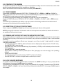
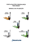
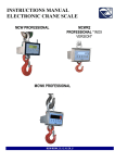
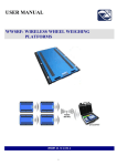
EXAMPLE: to calculate the barycentre of a 4-wheel vehicle with a weighing system having the scales arranged as shown in
the figure below, one must position the vehicle on the scales, press the 5 key and enter the following parameters:
Y
(INTER AXLE)
19
18
SCALE 2
SCALE 3
SCALE 1
SCALE 4
17
16
15
14
13
12
11
10
9
8
7
6
5
4
3
2
1
0
0
SCALE 1:
X.WhEL.1: 0,000
Y.WhEL.1: 0,000
SCALE 2:
X.WhEL.2: 0,000
Y.WhEL.2: 15,000
SCALE 3:
X.WhEL.3: 13,000
Y.WhEL.3: 15,000
SCALE 4:
X.WhEL.4: 13,000
Y.WhEL.4: 0,000
1
2
3
4
5
6
7
8
9 10 11 12
9.9 QUICK FORMATTING OF THE WEIGHT DATA PRINTING
Refer to the instrument’s technical manual (TECH.MAN.REF.).
25
13 14 15 16
X
(TRACK GAUGE)
DFWKR
10. WHEEL WEIGHING APPLICATIONS
10.1 SIMPLE WHEELS/AXLES WEIGHING
(for applications in which the NUMBER OF VEHICLE WHEELS = NUMBER OF INSTRUMENT’S SCALES)
1)
2)
3)
4)
Carry out a cycle of zero.
Position the vehicle on the scale and read the weight on the display.
By pressing ENTER, the formatted weight data is printed (see section 8.9).
Take the vehicle off the scale.
10.2 WEIGHING WITH AXLE TOTALISATION
(for applications in which the NUMBER OF VEHICLE WHEELS > NUMBER OF INSTRUMENT’S SCALES)
1) Carry out a cycle of zero
2) Put the first axle of the vehicle onto the platforms
3) press F: the weight of the vehicle is totalized, and if enabled, the configured weight data is printed.
4) Take the vehicle off the platforms
5) Put the next axle onto the platforms
6) press F: the weight of the axle is totalized and if enabled, the configured weight data is printed.
7) Take the vehicle off the platforms
8) Repeat operations 5, 6, and 7 for all the remaining axles.
9) Press the ENTER key: the total weight of the vehicle will be printed and cleared automatically (obtained from the
sum of the axles).
Furthermore the number of weighed vehicles and the relative total will be incremented.
It is also possible to automatically print the total weight of the vehicle (see section 9.2 for further information).
ZEROING (AND PRINTING) THE VEHICLES TOTAL
In order to zero the vehicles total one should press at length the ENTER/PRINT key with the zeroed vehicle total. The
display shows the message "V. totAL" and the vehicle total is zeroed. If the instrument has been enabled, the weight data
relative to the vehicle total accumulated until that moment, is printed.
CANCELLING A WEIGH IN EXECUTION
If a wrong totalisation has been made, it is possible to cancel the executed weigh.
Press the C key; the message "CL.SuM?" is displayed: press ENTER to zero the vehicle total, or press the C key to exit
without making modifications.
IMPORTANT
The procedure shown previously is usable with both 2 and 4 platform systems.
26
DFWKR
10.3 SIMPLE INPUT/OUTPUT FUNCTIONING MODE
(for applications in which the NUMBER OF VEHICLE WHEELS = NUMBER OF INSTRUMENT’S SCALES)
It is possible to use the instrument for input/output weighing without weight totalisation:
1) Carry out a cycle of zero.
2) Enter the number of vehicle’s wheels which one wants to weigh.
Execution of the input weigh:
3) Load the vehicle and press the 8 key; the message " tot.in " appears on the display and, if set, the weight data
relative to the input weigh made is printed.
Execution of the output weigh
4) Load the vehicle and press the 9 key; the message " tot.out " appears on the display and, if set, the weight data
relative to the input weigh made is printed.
5) The instrument automatically calculates the difference between the input and output weight and, if set, the weight is
printed.
Depending on the result obtained, the increment of the total of vehicles is managed in a different way:
INPUT ≥ OUTPUT INPUT NET
The number of input weighs and the net input total are incremented.
INPUT < OUTPUT OUTPUT NET
The number of output weighs and the output net total are incremented.
ATTRIBUTING THE STORED TARE VALUE TO THE INPUT/OUTPUT WEIGH OR TO THE WEIGHT DIFFERENCE
It is possible to decide whether to subtract the stored tare value from the input weigh, the output weigh or the input/output
difference:
Input weight
One should enter the tare value before acquiring the input weigh.
Output weight
One should enter the tare value after acquiring the input weigh and before acquiring the output weigh.
Input/output difference
One should press the MODE + TARE keys: the message " t.inout " is shown on the display along with 000000; enter the
known tare value and press ENTER.
In this way one introduces a tare value (only manual) which is subtracted from the input/output difference.
ZEROING (AND PRINTING) THE VEHICLES TOTAL
In order to zero the vehicles total one should press at length the ENTER/PRINT key with the zeroed vehicle total. The
display shows the message "V. totAL" and the vehicle total is zeroed. If the instrument has been enabled, the weight data
relative to the vehicle total accumulated until that moment, is printed.
CANCELLING AN INPUT OR OUTPUT WEIGH
If a wrong weigh in input or in output has been made, it is possible to cancel it by pressing the C key: depending on whether
the weigh is in input or in output, either the message "CL.in ?" or "CL.out ?" will appear on the display; press ENTER to
cancel the weigh, C to exit without saving modifications.
Refer to section 9.7.
27
DFWKR
10.4 INPUT/OUTPUT FUNCTIONING MODE WITH AXLE TOTALISATION
(for applications in which the NUMBER OF VEHICLE WHEELS > NUMBER OF INSTRUMENT’S SCALES)
It is possible to use the instrument for input/output weighing without weight totalisation:
1)
Carry out a cycle of zero
Execution of the input weigh:
2) Load the first axle of the vehicle
3) press the 8 key; the message " tot.in " appears on the display and, if configured, the relative weight data is printed.
4) Unload the platforms
5) Load the following axle
6) press the 8 key; the message " tot.in " appears on the display and, if configured, the relative weight data is printed.
7) Unload the platforms
8) Repeat operations 5,6 and 7 for all the remaining axles
9) Press the ENTER key: the input weigh is ended, and if configured, the weight data relative to the output weigh
made is printed
Execution of the output weigh
10) Load the first axle of the vehicle
11) press the 9 key; the message " tot.in " appears on the display and, if configured, the relative weight data is printed.
12) Unload the platforms
13) Load the following axle
14) press the 9 key; the message " tot.in " appears on the display and, if configured, the relative weight data is printed.
15) Unload the platforms
16) Repeat operations 5,6 and 7 for all the remaining axles
17) Press the ENTER key: the output weigh is ended, and if configured, the weight data relative to the output weigh
made is printed
18) The instrument automatically calculates the difference between the input and output weight and, if set, the weight is
printed.
Depending on the result obtained, the increment of the total of vehicles is managed in a different way:
INPUT ≥ OUTPUT INPUT NET
The number of input weighs and the net input total are incremented
INPUT < OUTPUT OUTPUT NET
The number of output weighs and the output net total are incremented
For each of the weighs made, it is possible to automatically print the total weight of the vehicle, see section 9.2 for further
information.
28
DFWKR
ATTRIBUTING THE STORED TARE VALUE TO THE INPUT/OUTPUT WEIGH OR TO THE WEIGHT DIFFERENCE
It is possible to decide whether to subtract the stored tare value from the input weigh, the output weigh or from the
input/output difference:
Input – tare weight
One should enter the tare value before acquiring the input weigh
Output – tare weight
One should enter the tare value after acquiring the input weigh and before acquiring the output weigh.
Input/output – tare difference
One should press the MODE and TARE keys: the message " t.inout " is displayed along with 000000; enter the known tare
value and press ENTER.
In this mode one enters a tare value, only manual, which will be subtracted from the input/output difference.
ZEROING (AND PRINTING) THE VEHICLES TOTAL
In order to zero the vehicles total one should press at length the ENTER/PRINT key with the zeroed vehicle total. The
display shows the message "V. totAL" and the vehicle total is zeroed. If the instrument has been enabled, the weight data
relative to the vehicle total accumulated until that moment, is printed.
CANCELLING AN INPUT OR OUTPUT WEIGH
In case of a wrong input or output weigh has been made, it is possible to cancel by pressing the C key: depending on
whether the weigh is in input or in output, either the message "CL.in ?" or "CL.out ?" will appear; press ENTER to cancel the
weigh, C to exit without making modifications.
See section 9.7.
11. INSTRUMENT CONNECTED TO BATTERY OPERATED PRINTER
In a system made up of an indicator connected to its dedicated printer both are battery powered; and the printer is in
STAND-BY and powered only when in use. When printing is finished the printer returns to STAND-BY automatically. This
functioning is useful in order to reduce the energy absorbed by the battery when the printer is not being used.
In this configuration if one has the need to maintain the printer powered in order to replace the paper and for other upkeep
operations, see the following section.
12. TURNING ON PRINTER IN ENERGY SAVING MODE
If the indicator is connected to a printer and if PWr.int or Ext.oFF parameter has been selected in SEtuP >> SEriAL >>
CoM.Prn >> PWr.Prn step in the TECHNICAL SETUP, one can turn on the printer (normally off) while weighing by
pressing the ZERO key at length.
On the display the blinking “onPri” message appears. In this condition one can carry out the upkeep operations on the
printer (paper replacement, adjustment of date and time). To exit this condition, press the C key.
29
DFWKR
13. INSTRUMENT MESSAGES DURING USE
MESSAGE
ZErO
buSy
unStAb
un.oVEr
LoW
no.0.unS
ConV.
no.ForM
Inout
no in
no out
no 1
no 2
Err.CLk
StorE
PrEC.
ErMOt
ErPnt
Er – 11
Er – 12
Er – 37
Er – 39
------
DESCRIPTION
The scale is zeroing the weight.
Print under way (PRN serial port occupied) or indicator waiting to transmit a print to the PC.
Unstable weight
One is trying to print with the weight in underload or in overload, i.e. beyond the maximum capacity or
below the minimum capacity
On one or more displayed scales there is a weight lower than the minimum weight foreseen for the tare,
the printout, the totalisation or the string (standard or extended) transmission, upon the pressing of the
print key.
Weight not passed by or instability
In standard mode, with approved instrument, one tries to print while the instrument is in the unit of
measure conversion.
Print not formatted, or in other words there are no parameters to be printed
One tries to totalize with the print key but an input/output weighing operation has been started
It is not possible to carry out an input weigh
It is not possible to carry out an output weigh
It is not possible to carry out the first weigh
It is not possible to carry out the second weigh
Communication problems with the date/time of the indicator: check the F.ModE >> CLoCk step of the
set-up (TECH.MAN.REF.).
It is displayed when data is stored in the instrument’s permanent memory (tares, ticket progressive, etc.)
It is displayed if one tries to calibrate the zero point without first having confirmed the number of
calibration points.
Weight unstable during the acquisition of a point during calibration.
During the acquisition of a calibration point a null value has been read by the converter.
Calibration error: a too small sample weight has been used; it is advisable to use a weight equal to at
least half of the scale capacity.
Calibration error: the acquired calibration point (tP1 o tP2 o tP3) is equal to the zero point (tP0).
The number of converter points per scale division is less than two. Carry out again the calibration with
special attention to the capacity and the division.
It is displayed when the instrument has not calibrated.
Press the TARE key to enter the technical set-up environment. Carry out the programming of all the
parameters of the set-up environment and the calibration.
Exit saving the changes made
Weight in underload or in overload, i.e. beyond the maximum capacity or below the minimum capacity.
30
DFWKR
DECLARATION OF CONFORMITY
This device conforms to the essential standards and norms relative
to the applicable European regulations. The Declaration of
Conformity is available in the web site www.diniargeo.com
WARRANTY
The TWO YEARS warranty period begins on the day the instrument
is delivered. It includes spare parts and labour repair at no charge if
the INSTRUMENT IS RETURNED prepaid to the DEALER’S
PLACE OF BUSINESS. Warranty covers all defects NOT
attributable to the Customer (such as improper use) and NOT
caused during transport.
If on site service is requested (or necessary), for any reason, where
the instrument is used, the Customer will pay for all of the service
technician’s costs: travel time and expenses plus room and board (if
any).
the Customer pays for the transport costs (both ways), if the
instrument is shipped to DEALER or manufacturer for repair.
The WARRANTY is VOIDED if any of the following occurs: repairs
or attempted repairs are made by unauthorised personnel,
connected to equipment installed by others, or is incorrectly
connected to the power supply, or instrument has defects or
damage due to carelessness or failure to follow the guidelines in this
instruction manual.
This warranty DOES NOT provide for any compensation for losses
or damages incurred by the Customer due to complete or partial
failure of instruments, even during the warranty period.
AUTHORIZED SERVICE CENTRE STAMP
31