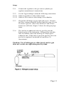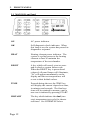
1
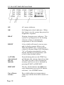
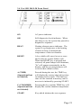
Arizona Instrument LLC
3375 N Delaware St
Chandler, AZ 85225
700-0002-B
(800) 528-7411
(602) 470-1414
Fax (480) 804-0656
http://www.azic.com
email:
[email protected] - General
[email protected] - International
[email protected] - Customer Support
TABLE of CONTENTS
INTRODUCTION . . . . . . . . . . . . . . . . . . . . . .
Program Options . . . . . . . . . . . . . . . . . . . . . .
Dual Program Systems . . . . . . . . . . . . . . . . . .
Deep Well Systems . . . . . . . . . . . . . . . . . . . . .
20-Gram Systems . . . . . . . . . . . . . . . . . . . . . .
MAX-10 . . . . . . . . . . . . . . . . . . . . . . . . . . . . .
Page 4
Page 6
Page 8
Page 8
Page 8
Page 8
INSTRUMENT SETUP . . . . . . . . . . . . . . . . . . Page 9
Instrument . . . . . . . . . . . . . . . . . . . . . . . . . . . Page 9
Printer Setup . . . . . . . . . . . . . . . . . . . . . . . . Page 10
Nitrogen Purge Setup . . . . . . . . . . . . . . . . . . Page 10
FRONT PANELS . . . . . . . . . . . . . . . . . . . . . .
MAX-50 . . . . . . . . . . . . . . . . . . . . . . . . . . . .
MAX-10 . . . . . . . . . . . . . . . . . . . . . . . . . . . .
Pre-1987 MAX-50 . . . . . . . . . . . . . . . . . . . .
Pre-1991 MAX-50 . . . . . . . . . . . . . . . . . . . .
Page 12
Page 12
Page 15
Page 18
Page 21
SAMPLE PREPARATION, TESTING AND
ANALYSIS . . . . . . . . . . . . . . . . . . . . . . . . . . .
Sample Preparation . . . . . . . . . . . . . . . . . . . .
Optimum Sample Size . . . . . . . . . . . . . . . . . .
Liquid Samples . . . . . . . . . . . . . . . . . . . . . . .
Determining Proper Test Temperatures . . . . .
HISTART Temperature . . . . . . . . . . . . . . . .
Page 24
Page 24
Page 24
Page 25
Page 26
Page 27
OPERATING PROCEDURES . . . . . . . . . . . .
MAX-50 Sample Testing Procedures . . . . . .
MAX-10 Sample Testing Procedures . . . . . .
Notes on Testing . . . . . . . . . . . . . . . . . . . . .
Printout of Results . . . . . . . . . . . . . . . . . . . .
Page 29
Page 29
Page 32
Page 36
Page 37
Page2
SYSTEM VERIFICATION . . . . . . . . . . . . . . .
Weight Test . . . . . . . . . . . . . . . . . . . . . . . . .
Sodium Tartrate Test . . . . . . . . . . . . . . . . . .
Retained Samples . . . . . . . . . . . . . . . . . . . . .
System Verification Log . . . . . . . . . . . . . . . .
RTD Spacing . . . . . . . . . . . . . . . . . . . . . . . .
Page 38
Page 38
Page 40
Page 41
Page 42
Page 42
SYSTEM DIAGNOSTICS . . . . . . . . . . . . . . . Page 43
Failure Codes . . . . . . . . . . . . . . . . . . . . . . . . Page 43
Error Indicators . . . . . . . . . . . . . . . . . . . . . . . Page 44
ROUTINE MAINTENANCE . . . . . . . . . . . . .
Chamber Interior . . . . . . . . . . . . . . . . . . . . . .
Sample Pan Support . . . . . . . . . . . . . . . . . . .
Force Balance . . . . . . . . . . . . . . . . . . . . . . . .
Shipping Instructions . . . . . . . . . . . . . . . . . . .
Page 45
Page 45
Page 45
Page 45
Page 46
MAX SPARE PARTS LIST . . . . . . . . . . . . . .
Consumables . . . . . . . . . . . . . . . . . . . . . . . . .
Spare Parts . . . . . . . . . . . . . . . . . . . . . . . . . .
Exchange Parts . . . . . . . . . . . . . . . . . . . . . . .
Accessories . . . . . . . . . . . . . . . . . . . . . . . . . .
Page 47
Page 47
Page 47
Page 48
Page 48
WARRANTY . . . . . . . . . . . . . . . . . . . . . . . . . Page 49
MAINTENANCE CONTRACT . . . . . . . . . . . Page 50
APPENDIX . . . . . . . . . . . . . . . . . . . . . . . . . . . Page 51
Printer Interface . . . . . . . . . . . . . . . . . . . . . . Page 51
Page 3
1.
INTRODUCTION
The MAX loss-on-drying moisture analysis system takes advantage
of computer technology to reduce test times and increase precision
over standard vacuum oven or convection oven drying procedures.
The sample is added to an aluminum sample pan sitting atop an
electronic force balance within a test chamber. As the sample
heats and loses weight due to moisture evaporation, the balance
records that weight loss and transmits the data to the
microprocessor. The microprocessor interprets the information
and compares the sample's weight loss to a standard drying curve.
The final moisture concentration is extrapolated from the curve
and results are available within minutes.
Atypical drying curve (Figure 1) consists of three portions-. The
first portion (A-B) represents the sample's weight loss as it heats
from room to testing temperature.
Section B-C is linear, representing moisture loss from the interior
of each particle of the tested sample. The final portion of the curve
(C-D) is exponential in nature and represents the final evolution of
moisture from within the particle. The point at which no
additional weight loss occurs represents the complete evolution of
water from the original sample (E).
Page 4
The final portion of the curve is the longest and most timeconsuming portion of the entire testing process. The time for a
sample to reach zero residual moisture can take from one to 24
hours depending upon the sample, sample preparation, and testing
temperature. The MAX loss-on-drying system calculates the
sample's moisture concentration through mathematical
extrapolation from the exponential (C-D) portion of the curve.
Between 1 gram and 1 0 grams of sample are placed onto an
aluminum sample pan in the test chamber. The aluminum pan sits
on a pan support coupled to a sensitive electronic force balance.
The force balance registers the initial weight of the sample prior to
testing and relays the sample's decreasing weight to the
microprocessor for evaluation. Balance readings are averaged to
eliminate signal interference or erroneous data.
Test temperatures can be programmed between ambient (25'C) and
225'C in either a one- or two-step temperature contour. Heating is
done through a 700-watt nichrome element which is located on the
underside of the test chamber's lid. An RTD (resistive temperature
device) monitors the temperature of the test chamber and relays
that information back to the microprocessor. Under the
microprocessor's control, the heater element is cycled on and off to
bring the test chamber to the programmed level within three
minutes of the test's start. The temperature is maintained within
2'C of the programmed temperature throughout the test.
A unique HISTART mode on the MAX 50 takes advantage of the
evaporative cooling effect at higher temperatures to reduce test
times and improve repeatability. When the HiSTART mode is
used, each cycle begins with a higher temperature setting to rapidly
evaporate moisture from the sample. The cooling effect of surface
evaporation prevents burning of the sample even though the
chamber temperature may be quite high (up to 225'C). During this
high temperature period, the sample's weight loss is closely
monitored to determine when the evaporation rate has decreased to
a point where the cooling effect is lost. To prevent sample
burning, the unit drops the temperature to the lower setting for
slower drying. The higher beginning test temperatures speed the
sample through the A-C portion of the drying curve. The lower
ending temperature takes the sample through the exponential
portion (C-D) of the curve where an accurate prediction of the
moisture concentration can be made.
Page 5
During the entire testing process the microprocessor monitors the
sample's weight loss. The sample's decreasing weight is compared
to the initial sample weight and the calculated moisture
concentration will appear on the display. Simultaneously, the
microprocessor is predicting a final moisture concentration based
upon the sample's rate of weight loss compared to the exponential
portion of a standard drying curve. Testing will continue until the
predicted moisture concentration agrees within a certain
percentage of the actual moisture concentration appearing on the
display. The percent agreement between the predicted and the
actual moisture concentrations will vary depending upon the
system's programming and the moisture level of the sample.
Program Options
There are four basic MAX programs, or ending criteria, available.
Program choice is dependent upon the sample's moisture level,
precision specifications and time considerations.
255 Program
In general, a "255" program is used for high moisture samples
such as slurries or foodstuffs. A 255 program will give quicker
final results and shorter test times because of a "looser" ending
criterion' The test will finalize when the difference between the
predicted and the actual moisture concentration agree within
0.64% to 0.74% of each other at sample moisture levels between
0% and 1 00%. The calculated standard deviation of results using
a 255 program can be as good as +/- 0.2% (1 S.D.).
97 Program
A "97" program can be used for high or low moisture samples.
Test times can be slightly longer than those for a 255 program for
the same sample. The 97 program requires a "tighter" agreement
between the actual and predicted moisture concentrations. The test
will continue through the drying curve until the predicted and
actual moisture concentrations agree within 0.24% to 0.34% of
each other at sample moisture levels from 0% to 100%. The
calculated standard deviation of results for a 97 program can be as
good as +/- 0. 1 % (1 S.D.).
Page 6
06 Program
An "06" program is typically used for low moisture samples where
a high degree of precision and sensitivity is required. Test times
will take longer than the two previous programs because the 06
requires the "tightest" agreement between the actual and predicted
moisture concentrations. The 06 program will continue testing
until the sample is almost dry. Agreement between the predicted
and actual moisture concentrations is between 0.015% and 0.12%
at moisture levels between 0% and 1 00%. The calculated standard
deviation of results using an 06 program can be as good as +/0.02% (1 S.D.).
500 Program
In general, a "500" program is used for very high moisture
samples that may change chemical composition under high heat.
A 500 program will give quicker final results and shorter test times
because it has the "loosest" ending criterion. The test will finalize
when the difference between the predicted moisture concentration
and the actual moisture concentration agree within 1.25% to
1.35% of each other at sample moisture levels between 0% and 1
00%. The calculated standard deviation of results using a 500
program can be as good as +/- 0.5% (1 S. D.).
Page 7
Dual Program Systems
MAX program packages are available which combine two
programs into one instrument. This feature increases the flexibility
of the unit when both high and low moisture sample testing is done
on the same instrument. Different programs are activated when
the START or HISTART key is pressed.
Deep Well Systems
Deep well systems are available for those samples which require a
large sample volume to reach the 7 gram recommended testing
weight. The heating element in a deep well system is located 4
inches above the sample pan, versus 2 inches in a standard MAX
unit. The recessed heater allows extra space for samples such as
paper, tobacco or rug fibers to be placed on the sample pan without
touching the heater element.
20-Gram Systems
Twenty-gram MAX units are available for testing extremely low
moisture samples such as plastic resins. A larger sample size (14
grams-18 grams) is used for each 20gram MAX test, thereby
increasing measurable moisture weight loss over a standard 1 0gram MAX unit.
MAX-10
For those applications requiring just one temperature for all
testing, a MAX-10 is available. The MAX-10 is factory set to the
user's optimum test temperature. Simple single button operation
increases testing reliability: the desired test temperature is always
used.
A wide variety of MAX systems and programs are available to
meet specific application requirements. Contact your account
representative at 1-800-528-7411 for assistance in determining
which combinations best fit the application.
Page 8
2. INSTRUMENT SETUP
2.1 Instrument
2.1.1
Place the MAX unit on a level, vibration-free work
surface to reduce errors in weight readings.
2.1.2
Insert the power cord into the receptacle on the rear panel
of the MAX unit. Connect the power cord to a 3-prong
grounded 110V/60 Hz outlet free from excess line voltage
fluctuations. (A line conditioner is available from Arizona
Instrument (AZI) to help solve line noise and voltage
fluctuation problems.)
2.1.3
Open the test chamber lid. Remove the tape securing the
sample pan support in position. Carefully lift the pan
support out of the test chamber, remove the foam spacer
block and replace the pan support in the tapered socket.
The pan support should slide easily into the tapered socket without
binding against the side of the guide tube. Use care when
inserting the support into the tapered socket, as excessive force
could cause damage to the weight sensor. When properly seated,
the four arms of the pan support should be approximately 1/4 inch
above the floor of the test chamber. If your pan support is metal
and not seated properly, remove it and gently bend the four arms
into proper position. If a plastic pan support is not seated properly,
call AZI Customer Service.
2.1.4
Depress the on/off rocker switch on the rear panel to
"ON". All front panel lights except OK and HEAT will
illuminate momentarily and four "8s" will appear on the
LED display. If the system passes its self-diagnostic
checks, the OK light will illuminate.
2.1.5
If a system malfunction is detected, a red SYSTEM
FAILURE light will illuminate below the display. A
numerical failure code will appear on the display. Refer
to Section VII, "System Diagnostics," for a complete
description.
Page 9
2.1.6
After a 20-minute warm-up, the MAX will be ready to test
samples. Note: Always let the system warm up after
power-up.
2.2
Printer Setup
2.2.1
Place the printer on a level surface, making sure it is
located far enough away from the MAX to avoid causing
vibration (a 15'cable is supplied).
2.2.2
Refer to the manual supplied with the printer for instructions on operation and usage.
2.2.3
Plug the RS232C "D" connector end (25 pin) of the
printer cable into the serial port on the rear of the printer.
The round pin connector end is plugged into the MAX
directly below the power cord at the lower left rear corner.
2.2.4
Verify that the printer is switched "on," selected "on line,"
and properly loaded with paper.
See page 37 for printout of results.
2.3
Nitrogen Purge Setup
When testing samples with a high solvent content, or with a low
flash point, a nitrogen (or another inert gas) atmosphere may be
desired to reduce the potential for ignition. If the unit has hose
barb fittings on the back of the lid and on the rear cavity panel, it
has been equipped to purge the heating chamber and the bottom
cavity with nitrogen.
The following materials will be required for the nitrogen purge
setup:
! Nitrogen source/cylinder
! Two-stage regulator
! Adjustable flow meter capable of measuring 0.5-4.0
liters/minute
! 3/16" inside diameter, 5/16" outside diameter Tygon
tubing
Page 10
Setup:
2.3.1
Connect the regulator to the gas source/cylinder per
regulator manufacturer's instructions.
2.3.2
Use the Tygon tubing to make the following connections:
2.3.2.1 Outlet of regulator to inlet of flow meter
2.3.2.2 Outlet of flow meter to inlet fitting of test chamber.
2.3.3
Check that all fittings are gas tight and secure. Pressure
and flow settings should be deterred until the start of a test
to conserve gas use. (Flow rates between 2 and 4 liters/
minute are sufficient.) Figure 2 shows the nitrogen purge
setup.
2.3.4
The unit has an additional inlet for gas flow into the
bottom cavity of the instrument. Nitrogen flow into this
inlet will further reduce the build-up of volatile gases
within the unit. If this inlet is used, the gas flow does not
need to be regulated, but should be kept below 20
liters/minute.
Caution: Use of nitrogen or other inert carrier gas
does not create an explosion-proof system.
Page 11
3.
FRONT PANELS
3.1 MAX-50 Front Panel
ON
AC power indicator.
OK
Self-diagnostic check indicator. When
this lamp is on, the system has passed its
diagnostics sequence.
HEAT
Heating element power indicator. The
system is cycling power to the heating
element to heat or maintain the
temperature of the test chamber.
RESET
A key which will cancel a test or erase
and re-check a system failure code.
When the RESET key is pressed and
released, all panel lamps will illuminate,
"8s" will appear momentarily on the
display and the test temperatures will
revert to their default values.
TIME
Pressed during the test, the TIME key
will display the current elapsed test time,
in minutes and seconds. The final test
time will be retained in memory until a
new test is initiated by pressing START
HISTART
The key which initiates the dual (two
step) temperature test cycle for shorter
test times. See HITEMP SP below
Page 12
Up or Down
Arrows
Keys which adjust test temperatures
either up or down from their current set
point.
HITEMP SP
High temperature set point. Pressing this
key will display the currently
programmed HISTART temperature.
Pressing this key simultaneously with
either the "up"or "down" arrow key will
change the HISTART temperature.
TEMP
Pressing this key will display the current
chamber temperature.
START
Key which initiates the single (one-step)
temperature test sequence.
LOAD
Indicator lamp that signals the end of the
tare weight sequence. Test sample can be
added to the sample pan after this
illuminates.
CLOSE
Lamp that indicates sufficient sample has
been added to the sample pan. The lid
must now be closed for the test to
continue. The CLOSE lamp is accompanied by an audible beep which will
continue until the lid is closed.
CHECK
A reminder to remove the previously
tested sample and sample pan from the
test chamber. This light may come on
momentarily when the START key is
pressed. Should the CHECK light
remain lit, make sure that only one pan
was placed on the pan support.
% SAMPLE
A key which, when pressed, displays the
amount of sample added to the sample
pan as a percentage of the balance's full
load capacity. For example, 3 grams is
about "30% sample" of a 1 0-gram
balance.
Page 13
% MOIS
Percent moisture. Pressing this key
during a test will display the sample's
actual weight loss as a percentage of the
initial weight. At the end of a test, the
displayed value will be the predicted
moisture concentration of the sample.
% SOLIDS
Pressing this key during a test will
display the residual sample weight on the
pan as a percentage of the initial weight.
At the end of the test, pressing this key
will display the predicted solids
concentration of the sample.
TEMPSP
Temperature set point. Pressing this key
will display the currently programmed
test temperature for the START mode.
Press this key simultaneously with the
"up" or "down" arrow keys to change the
desired temperature.
PREDICT
Predicted value. Pressing this key will
display the current predicted ending
result. This is an approximate test result.
If a prediction has not yet been computed,
a 0.00% indication is displayed.
FINAL
Indicator for the end of a test. The
displayed value will then be the predicted
moisture or solids concentration of the
sample.
UNSTAB
WEIGHT
Denotes erratic weight readings during
the load-weighing sequence of the test.
It may also light during the drying cycle
indicating that the lid was open for an
excessive amount of time.
SYSTEM FAIL
Illuminates when an internal system
malfunction has been detected. An error
code will appear on the display to signify
the type of failure detected. See page43
for a description of system failure codes.
Page 14
3.2 MAX-10 Front Panel
ON
AC power indicator
OK
Self-diagnostic check k indicator. When
this lamp is on, the system has passed its
diagnostics sequence.
HEAT
Heating element power indicator. The
system is cycling power to the heating
element to heat or maintain the
temperature of the test chamber.
RESET
A key which will cancel a test or erase
and re-check a system failure code.
When the RESET key is pressed and
released, all panel lamps will illuminate,
"8s" will appear momentarily on the
display and the test temperatures will
revert to their default values.
TIME
Pressed during the test, the TIME key
will display the current elapsed test time,
in minutes and seconds. The final test
time will be retained in memory until a
new test is initiated by pressing START.
Page 15
HISTART
Not Operative.
Up or Down
Arrows
Not Operative.
HITEMP SP
Not Operative.
TEMP
Pressing this key will display the current
chamber temperature.
START
Key which initiates the test sequence.
LOAD
Indicator lamp that signals the end of the
tare weight sequence. Test sample can be
added to the sample pan after this
illuminates.
CLOSE
Lamp that indicates sufficient sample has
been added to the sample pan. The lid
must now be closed for the test to
continue. The CLOSE lamp is accompanied by an audible beep which will
continue until the lid is closed.
CHECK
A reminder to remove the previously
tested sample and sample pan from the
test chamber. This light may come on
momentarily when the START key is
pressed. Should the CHECK light
remain lit, make sure that only one pan
was placed on the pan support.
% SAMPLE
A key which, when pressed, displays the
amount of sample added to the sample
pan as a percentage of the balance's full
load capacity. For example, 3 grams is
about "30% sample" of a 1 0-gram
balance.
% MOIS
Percent moisture. Pressing this key
during a test will display the sample's
actual weight loss as a percentage of the
initial weight. At the end of a test, the
displayed value will be the predicted
moisture concentration of the sample.
Page 16
% SOLIDS
Pressing this key during a test will
display the residual sample weight on the
pan as a percentage of the initial weight.
At the end of the test, pressing this key
will display the predicted solids
concentration of the sample.
TEMPSP
Temperature set point. Pressing this key
will display the programmed test
temperature.
PREDICT
Predicted value. Pressing this key will
display the current predicted ending
result. This is an approximate test result.
If a prediction has not yet been computed,
a 0.00% indication is displayed.
FINAL
Indicator for the end of a test. The
displayed value will then be the predicted
moisture or solids concentration of the
sample.
UNSTAB
WEIGHT
Denotes erratic weight readings during
the load-weighing sequence of the test. It
may also light during the drying cycle
indicating that the lid was open for an
excessive amount of time
SYSTEM FAIL
Illuminates when an internal system
malfunction has been detected. An error
code will appear on the display to signify
the type of failure detected.
See page43 for a description of system
failure codes.
Page 17
3.3 Pre-1987 MAX-50 Front Panel
ON
AC power indicator.
OK
Self-diagnostic check indicator. When
this lamp is on, the system has passed its
diagnostics sequence
HEAT
Heating element power indicator. The
system is cycling power to the heating
element to heat or maintain the
temperature of the test chamber.
RESET
A key which will cancel a test or erase
and re-check a system failure code.
When the RESET key is pressed and
released, all panel lamps will illuminate,
"8s" will appear momentarily on the
display and the test temperatures will
revert to their default values.
A (TIME)
(Operational
but not
labeled)
Pressed during the test, the TIME key
will display the current elapsed test time.
The final test time will be retained in
memory until a new test is initiated by
pressing START or HISTART.
HISTART
The key which initiates the dual (two
step) temperature test cycle for shorter
test times. See HITEMP below.
Up or Down
Arrows
Keys which adjust test temperatures
either up or down from their current set
point.
Page 18
B (HITEMP)
(Operational but
not labeled)
High temperature set point. Pressing this
key simultaneously with the TEMP key
will display the currently programmed
HISTART temperature. Pressing these
keys simultaneously with either the
"up"or "down" arrow key will change the
HISTART temperature.
C (CHAMBER)
(Operational but
not labeled)
Pressing this key simultaneously with the
TEMP key will display the current
chamber temperature (less 19OC).
START
Key which initiates the single (one-step)
temperature test sequence.
LOAD
Indicates the end of the tare weight
sequence. Test sample can be added to
the sample pan after this illuminates.
CLOSE
Lamp that indicates sufficient sample has
been added to the sample pan. The lid
must now be closed for the test to
continue. The CLOSE lamp is accompanied by an audible beep which will
continue until the lid is closed.
CHECK
A reminder to remove the previously
tested sample and sample pan from the
test chamber. This lamp may come on
momentarily when the START key is
pressed. Should the CHECK lamp
remain lit, make sure that only one pan
was placed on the pan support.
% SAMPLE
A key which, when pressed, displays the
amount of sample added to the sample
pan as a percentage of the balance's full
load capacity. For example, 3 grams is
about "30% sample" of a 1 0-gram
balance.
Page 19
% MOIS
Percent moisture. During a test this key,
will display the sample's actual weight
loss as a percentage of the initial weight.
At the end of a test, the displayed value
will be the predicted moisture concentration of the sample.
% SOLIDS
During a test, this key will display the
residual sample weight on the pan as a
percentage of the initial weight. At the
end of the test, this key will display the
predicted solids concentration of the
sample.
TEMP
Temperature set point. This key will
display the currently programmed test
temperature for the START mode. Press
this key simultaneously with the "up" or
"down" arrow keys to change the desired
temperature.
D (PREDICT)
(Operational
but not
labeled)
Predicted value. Pressing this key will
display the current predicted ending
result. This is an approximate test result.
If a prediction has not yet been computed,
a 0.00% indication is displayed.
FINAL
Indicator for the end of a test. The
displayed value will then be the predicted
moisture or solids concentration of the
sample.
UNSTAB
WEIGHT
Denotes erratic weight readings during
the load-weighing sequence of the test. It
may also light during the drying cycle
indicating that the lid was open for an
excessive amount of time.
SYSTEM FAIL
Illuminates when an internal system
malfunction has been detected. An error
code will appear on the display to signify
the type of failure detected. See page 43
for a description of system failure codes.
Page 20
3.4 Pre-1991 MAX-50 Front Panel
ON
AC power indicator.
OK
Self-diagnostic check indicator. When
this lamp is on, the system has passed its
diagnostics sequence.
HEAT
Heating element power indicator. The
system is cycling power to the heating
element to heat or maintain the
temperature of the test chamber.
RESET
A key which will cancel a test or erase
and re-check a system failure code.
When the RESET key is pressed and
released, all panel lamps will illuminate,
"8s" will appear momentarily on the
display, and the test temperatures will
revert to their default values.
A (TIME)
(Operational but
not labeled)
Pressed during the test, the TIME key
will display the current elapsed test time,
in minutes and seconds. The final test
time will be retained in memory until a
new test is initiated by pressing START.
C (CHAMBER)
(Operational but
not labeled)
Pressing this key and the TEMP key will
display the current chamber temperature.
START
Key which initiates the test sequence.
Page 21
LOAD
Indicator lamp that signals the end of the
tare weight sequence. Test sample can be
added to the sample pan after this
illuminates.
CLOSE
Lamp that indicates sufficient sample has
been added to the sample pan. The lid
must now be closed for the test to
continue. The CLOSE lamp is accompanied by an audible beep which will
continue until the lid is closed
CHECK
A reminder to remove the previously
tested sample and sample pan from the
test chamber. This lamp may come on
momentarily when the START key is
pressed. Should the CHECK lamp
remain lit, make sure that only one pan
was placed on the pan support.
% SAMPLE
A key which, when pressed, displays the
amount of sample added to the sample
pan as a percentage of the balance's full
load capacity. For example, 3 grams is
about "30% sample" of a 1 0-gram
balance.
% MOIS
Percent moisture. During a test this key
will display the sample's actual weight
loss as a percentage of the initial weight.
At the end of a test, the displayed value
will be the predicted moisture concentration of the sample.
% SOLIDS
During a test this key will display the
residual sample weight on the pan as a
percentage of the initial weight. Pressing
this key at the end of the test will display
the predicted solids concentration of the
sample.
TEMP
Pressing this key will display the programmed test chamber.
Page 22
B (PREDICT)
(Operational but
not labeled)
Predicted value. Pressing this key will
display the current predicted ending
result. This is an approximate test result.
If a prediction has not yet been computed,
a 0.00% indication is displayed.
FINAL
Indicator for the end of a test. The
displayed value will then be the predicted
moisture or solids concentration of the
sample.
UNSTAB
WEIGHT
Denotes erratic weight readings during
the load-weighing sequence of the test. It
may also light during the drying cycle
indicating that the lid was open for an
excessive amount of time.
SYSTEM FAIL
Illuminates when an internal system
malfunction has been detected. An error
code will appear on the display to signify
the type of failure detected.
See page 43 for a description of system
failure codes.
Page 23
4.
SAMPLE PREPARATION, TESTING AND ANALYSIS
4.1 Sample Preparation
The MAX system can be used to test a wide range of products from
finely ground, low-moisture powders to high-moisture slurries.
For best results, the sample should be of a uniform particle size
and homogeneous in nature. Large chunk samples, such as
charcoal or cookies, should be finished or ground to smaller pieces
approximately 1/4" or less in diameter. Some samples, such as
dried vegetables, may also need to be ground. The smaller pieces
will easily release their moisture during testing, leading to shorter
test times and more repeatable results.
Any sample tested for moisture should be as uniform as
possible. If sample material is collected into a jar or sampling bag,
shake the jar or bag to produce a uniform mixture. Liquid samples
should also be mixed or shaken to ensure a more homogeneous
mixture.
Solid, granular sample material should be shaken onto the pan
from a spoon; shaking sample directly from the collection jar will
usually deposit only the larger granules, not a representative
mixture. Liquid samples or slurries can be spooned or poured onto
the sample pan; however, a pipette or sampling straw will collect a
more homogeneous mixture of sample.
4.2 Optimum Sample Size
Each particular sample will have its own optimum sample size. A
rule of thumb is "the lower the moisture, the larger the sample."
Low-moisture samples (less than 1%), such as chemicals, require
larger amounts of sample (70% to 90% of force balance capacity).
The larger sample size is necessary to provide sufficient weightloss information to the microprocessor. A larger weight change
between the initial and final sample weights will give more
accurate, repeatable results.
High-moisture samples can be tested with smaller sample sizes
(30% to 40% of force balance capacity). Since there is a large
enough change in weight between the initial and final sample
weights, accurate results can be predicted. A larger sample size
will only increase test times.
Page 24
Samples with moisture levels between 1% and 30%, approximately, can usually be run with 50% sample size.
The sample should be added evenly across the entire surface of
the pan. Once the desired amount of sample has been added, the
pan can be removed from the test chamber to evenly distribute the
sample. The sample should be distributed over the surface by
gentle shaking, tapping, or in the case of very viscous samples,
spread with a spoon or knife. Do not spread granular products
with a spoon; the particles have a tendency to compress even under
gentle pressure, affecting test times and results. An even layer of
sample across the pan will reduce test times and increase precision
of results.
4.3 Liquid Samples
Some liquid samples will dry slowly, even at high temperatures.
Drops or puddles may form on the pan which dry slowly as the
sample concentrates. A skin may form which limits evaporation
from the interior. Long test times (greater than 45 minutes) and
low % moisture (or high % solids values) indicate incomplete
drying. Pre-dried glass fiber filter paper and flat bottomed pans
are recommended to successfully test samples such as these.
Filter paper serves as a support for the liquid sample. The sample
is absorbed through the paper where a more even, rapid
evaporation occurs, thereby reducing test times.
Occasionally, some samples can not be absorbed into the filter
paper. At the end of the test, examination of the sample pan shows
the sample sitting high above the filter paper with a thick crust.
The crust may be singed from the heat or even show bubbling
where vapor has collected beneath the surface. % SOLIDS results
will be high or % MOISTURE results will be low. Samples such
as these are treated slightly differently: after the sample has been
added to the sample pan, remove the pan from the test chamber
and place ft onto a flat surface. Grasp a portion of the filter paper
and flip ft over so that the sample lies
Page 25
between the pan and the paper. Squash the sample with a flatbottomed glass or jar to a uniform layer. Return the sample pan to
the test chamber and close the lid. The upper filter paper surface
absorbs moisture from the sample and prevents spattering to
produce more accurate, reproducible results.
The glass-fiber filter paper must be pre-dried before use. Several
sheets can be dried conveniently in a MAX at 150'C. After drying,
store the filter paper in a desiccator to prevent the absorption of
ambient humidity. Waffle-bottomed sample pans are not
recommended for use with filter paper. The liquid sample may
soak through the filter paper and collect in puddles in the pan's
depressions.
4.4 Determining Proper Test Temperatures
To determine the proper test temperature for a particular sample,
prepare a 'Temperature versus moisture" curve. Sample material is
tested at increasing temperatures, usually in five or ten degree
increments. If the moisture concentration of the sample material is
known, as determined with a reference method (vacuum or air
oven), then the MAX's temperature can be adjusted until the
MAX's test results correlate with the known moisture concentration.
The starting temperature is usually the standard or reference
method temperature for that particular sample. Results for each
increasing temperature will usually rise to a plateau where several
increasing temperatures do not change the results significantly.
Beyond this plateau results rise dramatically. (See Figure 3 on
next page.) Examination of the tested sample shows burning or
charring.
Results along this plateau usually correlate well with the standard
or reference method results. Repeated testing should be done at
temperatures in this range. Several tests are performed using the
same sample size and test parameters. Results from these repeated
tests are tabulated to calculate the mean, or average, and the
standard deviation (S.D.). Analysis of the mean and standard
deviation, and their comparison with reference method results,
determines d the proper test temperature has been used. If mean
values do not compare well, or d the standard deviation is too
large, test at another temperature along the plateau.
Page 26
4.5 HISTART Temperature
The HISTART feature of the MAX shortens test times by rapidly
evaporating moisture from a sample without degradation or
burning. At high temperatures (up to 225'C) the cooling effect of
evaporation will prevent the sample from burning. Sample weight
is monitored carefully by the microprocessor during the high
temperature cycle: when there is insufficient water left in the
sample to cool the surface, the MAX will drop from the HISTART
set point to the TEMP SP (usually a lower temperature) for the
duration of the test.
After an optimum test temperature for the sample has been
determined, the HISTART feature can be used. Set the test
temperature to the established setting using the TEMP SP and the
"up" or "down" arrow keys. Adjust the HISTART temperature to
ten degrees above the predetermined test temperature using the H
ITEM P SP and the "up" or "down" arrow keys. Place a clean
sample pan onto the pan support in the test chamber and press the
HISTART key. The test will run in a dual temperature mode.
After the TIME and % MOISTURE or % SOLIDS results are
recorded, increase the HITEMP SP another ten degrees, leaving
Page 27
the TEMP SP setting as it is. Repeat the test. As the HISTART
temperature is increased, test times will decrease while the result s
remain comparable to those run in a single temperature test.
However, beyond a certain HISTART temperature the system does
not cool to the lower temperature fast enough without burning the
sample, producing unacceptable results. Repeated testing should
be done at those temperature settings where results are acceptable.
Page 28
5. OPERATING PROCEDURES
5.1 MAX-50 Sample Testing Procedures
5.1.1
Pre-Test Purge and Gas Flow (if used):
5.1.1.1 Open the valve at the gas source/cylinder and adjust the
regulator to an outlet pressure between 6 and 1 0 psi.
5.1.1.2 Adjust the flow meter to the desired flow rate through the
test chamber. Gas flow should be kept below 4
liters/minute. Flows greater than 4 liters/minute could affect test results by causing excess turbulence in the test
chamber. If a gas flow is to be introduced into the bottom
cavity, the flow rate should be kept below 20 liters/minute.
Note: The lid must be closed before the START key is pressed
when a purge gas is used to vent the test chamber.
Caution: Use of nitrogen or other Inert carrier gas
does not create an explosion-proof system.
5.1.2
Test Procedures:
5.1.2.1 Let the system warm up for 20 minutes.
5.1.2.2 Press the HITEMP SP key to display the currently
programmed Initial testing temperature. If necessary, use
the "up" or "down" arrow keys while simultaneously
pressing the HITEMP SP key to change to another initial
temperature.
5.1.2.3 Press the TEMP SP key to display the current testing
temperature. If necessary, use the "up" or "down" arrow
keys to change to another testing temperature.
5.1.2.4 Place a clean aluminum sample pan onto the sample pan
support in the test chamber. For the best results, always
use a clean pan that is not deformed. If filter paper is
required for the application, place the paper onto the
sample pan. Close the chamber lid.
Page 29
The lid must be closed when the START key is pressed to assure
greatest accuracy and precision. The force exerted by air flow onto
the sample pan must be equal between the tare sequence and the
test portion of the cycle.
5.1.2.5 Press the START key to begin a test. If a dual temperature test is desired, press the HISTART key. The unit will
perform a tare weight reading on the sample pan and store
that weight into memory. If the CHECK lamp
illuminates, verify that only one sample pan was placed
onto the pan support. If the CHECK lamp is still
illuminated, use another sample pan or refer to Section
VII, "System Diagnostics."
5.1.2.6 When the LOAD lamp illuminates, open the chamber lid
and add test material to the sample pan. With a standard
program, the instrument will beep and the CLOSE lamp
will illuminate when approximately 7 grams of material
has been deposited onto the pan. At least 7 grams of test
material must be added to the pan for the test sequence to
continue (or 14 grams of material for a 20-gram MAX
unit).
If a smaller amount of sample or a consistent sample size is
required, press the % SAMPLE key when the LOAD lamp
illuminates. As test material is added to the sample pan, the
display will show the weight relative to the balance's capacity. For
example, "50% sample" is equal to approximately 5 grams of
sample on a 10-gram MAX unit or 1 0 grams of sample on a 20gram unit. A minimum of 10% sample is required for the testing
sequence to continue.
The test material should be evenly deposited over the sample
pan. If necessary, the sample pan can be temporarily removed
from the instrument to distribute the test material more evenly.
5.1.2.7 Return the pan to the pan support and close the lid. The
weight of the sample will be measured and recorded by
the unit and the test chamber will be heated to the
programmed temperature.
Page 30
If a stable weight reading cannot be read due to rapid volatile
evaporation or excess vibration, an UNSTABLE WEIGHT lamp
will illuminate below the display. The test can be run to
completion, if desired, but results should be verified with
additional testing. The test can be canceled by pressing the
RESET key. Remove the sample pan from the test chamber and
begin a new test, starting with test procedure step #2.
5.1.2.8 During the test, the display will show the currently
calculated percent moisture loss or percent solids concentration of the sample, depending upon whether the %
MOIS or % SOLIDS key is activated. Pressing the TIME
key will display the elapsed test time. Pressing the
PREDICT key will show the calculated final moisture
concentration based upon the sample's rate of weight loss
thus far during the test sequence. Pressing the TEMP key
will monitor the chamber's temperature as the heater element heats it to the desired testing temperature and maintains it during the test.
5.1.2.9 When the actual moisture concentration of the sample
agrees with the predicted moisture concentration within
the program's specified limits, the test will end. The
MAX will emit three short beeps; the % MOIS and
FINAL lamps will illuminate; and the final, predicted
moisture concentration will be displayed. The CHECK
lamp will also light as a reminder to remove the tested
sample from the chamber. Because the final moisture
concentration has been mathematically calculated,
moisture remains in the tested sample at the end of the
test. This remaining moisture has been considered in the
final moisture concentration displayed.
5.1.2.10 If the solids content of the sample is of interest, press the
% SOLIDS key to display that value. To determine the
test time, press the TIME key to display the minutes and
seconds ("4.53" equals 4 minutes and 53 seconds).
The % MOIS and % SOLIDS results and the TIME, HITEMP SP
and TEMP SP values will be retained in memory until the RESET
or START key is pressed. It is not necessary to press the RESET
key to erase these values from the display. If the RESET key is
pressed, memory is erased and the test temperatures will revert to
Page 31
the default programming.
NOTE: For best results, allow the chamber to cool three to
four minutes (chamber temperature should be less than 40oC)
before starting the next test. Open the instrument's lid for faster
cooling. The chamber temperature can be monitored through the
TEMP key which displays the temperature of the test chamber. If
the unit has special programming which permits back-to-back
testing ("load and go"), the next test can be started when the
chamber temperature is approximately 50'C.
5.1.2.11 Remove the sample pan containing the previously tested
material from the test chamber and dispose of ft. If the
next test will use the same test temperature, begin the next
test sequence with test procedure step #4. If the sample
requires different test temperature programming, begin
the next test sequence with step #2.
5.2 MAX-10 Sample Testing Procedures (Single Temperature
Model)
5.2.1
Pre-Test Purge and Gas Flow (if used):
5.2.1.1 Open the valve at the gas source/cylinder and adjust the
regulator to an outlet pressure between 6 and 10 psi.
5.2.1.2 Adjust the flow meter to the desired flow rate through the
test chamber. Gas flow should be kept below 4
liters/minute. Flows greater than 4 liters/minute could affect test results by causing excess turbulence in the test
chamber. If a gas flow is to be introduced into the bottom
cavity, the flow rate should be kept below 20 liters/minute.
Caution: Use of nitrogen or other Inert carrier gas
does not create an explosion-proof system.
Note: The lid must be closed before the START key is
pressed when a purge gas is used to vent the test chamber.
5.2.2
Test Procedures:
5.2.2.1 Let the system warm up for 20 minutes.
Page 32
5.2.2.2 Place a clean aluminum sample pan onto the sample pan
support in the test chamber. For the best results, always
use a clean pan that is not deformed. If filter paper is
required for the application, place the paper onto the
sample pan. Close the chamber lid.
The lid must be closed when the START key is pressed to assure
greatest accuracy and precision. The force exerted by air flow onto
the sample pan must be equal between the tare sequence and the
test portion of the cycle.
5.2.2.3 Press the START key to begin a test. The unit will
perform a tare weight reading on the sample pan and store
that weight into memory. If the CHECK lamp
illuminates, verify that only one sample pan was placed
onto the pan support. It the CHECK lamp is still
illuminated, use another sample pan or refer to Section VI
1, "System Diagnostics."
5.2.2.4 When the LOAD lamp illuminates, open the chamber lid
and add test material to the sample pan. With a standard
program, the instrument will beep and the CLOSE lamp
will illuminate when approximately 7 grams of material
has been deposited onto the pan. At least 7 grams of test
material must be added to the pan for the test sequence to
continue (or 14 grams of material for a 20-gram MAX
unit).
If a smaller amount of sample or a consistent sample size is
required, press the % SAMPLE key when the LOAD lamp
illuminates. As test material is added to the sample pan, the
display will show the weight relative to the balance's capacity. For
example, "50% sample" is equal to approximately 5 grams of
sample on a 10-gram MAX unit or 10 grams of sample on a 20gram unit. A minimum of 10% sample is required for the testing
sequence to continue.
The test material should be evenly deposited over the sample
pan. If necessary, the sample pan can be temporarily removed
from the instrument to distribute the test material more evenly.
5.2.2.5 Return the pan to the pan support and close the lid. The
weight of the sample will be measured and recorded by
Page 33
the unit and the test chamber will be heated to the
programmed temperature.
Page 34
If a stable weight reading cannot be read due to rapid volatile
evaporation or excess vibration, an UNSTABLE WEIGHT lamp
will illuminate below the display. The test can be run to
completion, if desired, but results should be verified with
additional testing. The test can be canceled by pressing the
RESET key, Remove the sample pan from the test chamber and
begin a new test, starting with test procedure step #2.
5.2.2.6 During the test, the display will show the currently
calculated percent moisture loss or percent solids concentration of the sample, depending upon whether the %
MOIS or % SOLIDS key is activated. Pressing the TIME
key will display the elapsed test time. Pressing the
PREDICT key will show the calculated final moisture
concentration based upon the sample's rate of weight loss
thus far during the test sequence. Pressing the TEMP key
'II monitor the chamber's temperature as the heater
element heats it to the desired testing temperature and
maintains it during the test.
5.2.2.7 When the actual moisture concentration ot the sample
agrees with the predicted moisture concentration within
the program's specified limits, the test will end. The
MAX will emit three short beeps; the % MOIS and
FINAL lamps will illuminate-, and the final, predicted
moisture concentration will be displayed. The CHECK
lamp will also light as a reminder to remove the tested
sample from the chamber. Because the final moisture
concentration has been mathematically calculated,
moisture remains in the tested sample at the end of the
test. This remaining moisture has been considered in the
final moisture concentration displayed.
5.2.2.8 If the solids content of the sample is of interest, press the
% SOLIDS key to display that value. To determine the
test time, press the TIME key to display the minutes and
seconds ("4.53" equals 4 minutes and 53 seconds).
The % MOIS and % SOLIDS results and the TIME values will be
retained in memory until the RESET or START key is pressed. It
is not necessary to press the RESET key to erase these values
from the display. If the RESET key is pressed, memory is erased.
Page 35
NOTE: For best results, allow the chamber to cool three to
four minutes (chamber temperature should be less than 40"(' )
before starting the next test. Open the instrument's lid for faster
cooling. The chamber temperature can be monitored through the
TEMP key which displays the temperature of the test chamber. If
the unit has special programming which permits back-to-back
testing ("load and go"), the next test can be started when the
chamber temperature is approximately 50'C.
5.2.2.9 Remove the sample pan containing the previously tested
material from the test chamber and dispose of it. Begin
the next test with test procedure step #2.
5.3 Notes on Testing
Some samples will cause moisture to visibly condense onto the
aluminum heater box, lid and inside of the test chamber. Simply
open the chamber lid after the test is completed to allow the burner
to cool and the droplets to evaporate. Under most circumstances
this condensation is not a problem. Exceptions are those samples
which may create corrosive vapors during the heating process such
as manganese dioxide, calcium hypochlorite or tire rubber. The
vapors collect within the burner assembly where they may not
readily dissipate. These vapors may damage and corrode the
wiring and connections within the heater assembly, which controls
heat maintenance and temperature control. Erratic sample
moisture results or assorted system failures may occur.
To minimize the effects of this corrosive condensate, run a weight
test periodically during testing. This heats the chamber,
evaporating the collected moisture without adding additional
vapors to the test chamber. The usable life of the burner is
extended and system accuracy is verified.
In severe cases, a vacuum line can be attached to a Computrac lid
with a purge fitting. The vacuum will draw corrosive vapors
directly from the test chamber before they can collect within the
burner assembly. A purge fitting can be added to any MAX
system. Contact your sales representative or AZI Customer Service
for details.
Page 36
5.4 Printout of Results (For MAX-10 and MAX-50)
The MAX will send results to the accessory printer at the
completion of each test. Results for single temperature tests will
print out in the following format: (this will print out on one line)
19 C AMBIENT 73% SAMPLE 180 DEG C
2.15% MOISTURE 04:53 TEST TIME U.W.
For dual temperature tests on the MAX-50, results will print out in
the following format: (this will print out on one line)
19 C AMBIENT 73% SAMPLE 180/150 DEG C
2.15% MOISTURE 04:53 TEST TIME U.W.
These printouts can be interpreted using the following legend:
AMBIENT - the test chamber temperature when the START key
was pressed
% SAMPLE - the amount of sample tested expressed as
percentage of the balance capacity
DEG C - the programmed testing temperature or TEMP SP. If
HISTART was used, both HITEMP SP and TEMP SP temperatures
will be displayed
% MOISTURE - the moisture concentration of the sample
TEST TIME - the elapsed test minutes and seconds
U. W. - indicates an unstable weight was determined during the
test
Page 37
6. SYSTEM VERIFICATION
Periodic checks of the system are recommended to verify proper
system operation. These periodic checks will satisfy some quality
control or quality assurance guidelines. A log is recommended
which will record the weight tests, sodium tartrate tests and
retained sample's results. Shifts in results that are out of range can
be quickly detected and the appropriate corrections made.
6.1 Weight Test
The "Weight Test" will check the system's balance and
accompanying electronics. Two weights, 5 grams and 3 grams
each, are placed upon the sample pan. After the full load weight
has been recorded into memory, one of the weights is removed to
simulate moisture loss. The use of two known weights will give
uniform sample size and uniform weight loss.
6.1.1
Switch the instrument on. Set the temperature to 150'C.
6.1.2
Wait 20 minutes for warm-up.
6.1.3
Place a clean aluminum sample pan onto the sample tray
support.
6.1.4
Close the lid and press the START button.
6.1.5
When the LOAD lamp illuminates, press % SAMPLE for
visible loading display.
6.1.6
Place the 3-gram and 5-gram weights (or 6-gram and 10gram weights for a 20-gram MAX) near the center of the
sample pan. Note: The instrument works on a percentage
basis only, so the display will read 80% (+/- 5%).
6.1.7
Close the door and wait for the HEAT Lamp to
illuminate, indicating the full load has been recorded.
6.1.8
Open the door and carefully remove the smaller weight
(either the 3-gram or 6-gram weight) without pressing
down on the sample pan. If a "Failure 1 " occurs, remove
the other weight, press the RESET button and restart the
Page 38
test beginning with Step #3. A "Failure 1" indicates the
sample pan was pushed down.
6.1.9
Close the door and let the instrument complete the cycle.
This test verities the accuracy of the instrument by
simulating a known % moisture loss.
% Moisture = Initial Weight - End Weight X 100%
Initial Weight
% Moisture = 8 grams - 5 grams X 100%
8 grams
% Moisture =
3 grams X 100%
8 grams
% Moisture = 37.5%
Acceptable % moisture result:
Range for all instruments except the Deep Well: 37.48% to
37.54%.
Range for Deep Well instrument: 37.46% to 37.54%
NOTE: The increased variation between results for the “Deep
Well” instrument is due to the increased volume in the heat
chamber. Please call AZI Customer Service at 1-800-528-7411 if
you have any questions about the acceptable limits.
Page 39
6.2 Sodium Tartrate Test
The sodium tartrate dehydrate test will verify the heater, force
balance and moisture prediction features. Sodium tartrate
dehydrate is a chemical with a known moisture concentration
which gives up moisture at temperatures greater than 120'C.
Because of its consistent moisture concentration, it has been used
as a standard in moisture measurement using oven or titration
methods. For best results, use a high quality or "reagent grade"
sodium tartrate. Avoid using sodium tartrate that contains lumps,
since lumps indicate the absorption of ambient humidity.
6.2.1
Switch the instrument on. Set the temperature to 140oC.
6.2.2
Wait 20 minutes for warm-up.
6.2.3
Place a clean aluminum sample pan onto the pan support
and close the lid.
6.2.4
Press the START key.
6.2.5
When the LOAD lamp illuminates, press the % SAMPLE
key for visible loading display. Add the sodium tartrate
evenly across the sample pan until 80% sample has been
added (40% sample on a 20-gram MAX unit).
6.2.6
Close the lid and allow the test to proceed.
High quality or "reagent grade" sodium tartrate dehydrate has a
known chemical composition consisting of approximately 15.66%
water (the exact percentage of water is stated on the container for
that particular lot). Results will vary according to the MAX
program used (06, 97 or 255) and chemical quality.
Page 40
6.3 Retained Samples
The weight test and the sodium tartrate dehydrate test are usually
sufficient to satisfy industry guidelines for quality control in
moisture measurement. Some additional checks can be performed
using replicate testing of retained samples. Retained samples,
when stored under airtight conditions, should maintain moisture
levels for long periods. Daily testing of these samples should
produce the same results day after day. Retained samples further
verify the unit's operation on the customer's own product.
6.3.1
Let the system warm up for 20 minutes.
6.3.2
Set the MAX to the optimum test temperature for the
retained sample.
6.3.3
Place a clean aluminum sample pan onto the pan support
in the test chamber.
6.3.4
Close the lid and push the START key.
6.3.5
When the LOAD lamp illuminates, press the % SAMPLE
key for visible loading display. Add the optimum amount
of retained sample evenly across the sample pan.
6.3.6
Close the lid and allow the test to continue.
6.3.7
Record the final result in the quality control log. The %
MOISTURE results for the retained sample should fall
within the established acceptable range of results for that
sample. If results are out of range, repeat the test to verify
results.
Page 41
6.4 System Verification Log
A log is recommended which will record the results of weight,
sodium tartrate and sample tests. Shifts in results out of range can
be quickly detected and the appropriate corrections made.
6.5 RTD Spacing
The temperature sensor, an RTD (resistive temperature device),
monitors and maintains test temperatures within two degrees of the
set point. To ensure the proper temperature at the sample's
surface, the sensor must be exactly one-quarter of an inch from the
surface of the burner element. This distance should be checked
periodically using the spacer gauge provided by AZI (a standard,
wooden #2 pencil, which is 1/4" across the flat surface, will work,
too). To check the distance, first make sure the burner element is
cool to the touch. Then place the gauge between the sensor and the
burner element. The gauge should fit snugly. If not, gently move
the sensor guard in or out to the required distance. See Figure 4.
Page 42
7.
SYSTEM DIAGNOSTICS
The MAX monitors the status and performance of all internal
systems for correct operation. If an abnormal condition is detected,
a diagnostic message is displayed on the alpha-numeric display
and the red SYSTEM FAIL lamp will illuminate. The instrument
will attempt to correct the condition. If corrected, the diagnostic
message will disappear. If the message reappears, or if the
condition persists, call AZI Customer Service at 1-800-528-7411 or
1-602-470-1414.
7.1 Failure Codes
System
Failure
Cause
0 or
no display
Processor failure
1
Analog input over range (abnormal
condition was detected in signal from
either the heater or the balance)
2
Internal negative reference voltage out of
range
(internal or external power source
problem)
3
Internal POsitive reference voltage out of
range
(internal or external power source
problem)
4
Temperature control failure
Page 43
7.2 Error Indicators
An UNSTABLE WEIGHT lamp indicates weight readings that are
out of program specifications. The point in the test at which the
UNSTABLE WEIGHT light comes on indicates the cause of the
problem detected. Should the lamp illuminate during the heating
cycle, it may be due to the lid being open for an excessive amount
of time. When the UNSTABLE WEIGHT lamp comes on
immediately following the initial, full-load sample weighing cycle,
the test chamber may have been too warm to start the next test,
causing water to evaporate from the sample and resulting in
uneven weight readings. Another source of uneven weight
readings may be vibration caused by an unstable bench or table
transmitting vibrations to the MAX from machinery or traffic near
the work area.
To establish the cause of an UNSTABLE WEIGHT lamp, run
sequential weight tests. If the UNSTABLE WEIGHT lamp does
not illuminate, testing may have been performed without letting
the system cool down between samples. if it continues to light,
move the instrument to a quiet work area isolated from external
vibrations. The continued presence ot the UNSTABLE WEIGHT
lamp when other causes have been eliminated may indicate a force
balance problem. Contact AZI Customer Service for additional
assistance.
The CHECK lamp comes on at the end of a test as a reminder to
remove the pan containing previously tested sample from the
chamber. It may light momentarily after the START key has been
pressed, even when a clean sample pan is in position. It the
CHECK lamp remains lit and the unit does not proceed to LOAD,
open the lid and check that only one pan has been placed on the
pan support. Replace the pan and close the lid. If the CHECK
lamp remains lit, call AZI Customer Service for assistance.
The RESET key is used to abort a test or to re-check a system
failure condition. Touch the key momentarily. All panel lamps
will light and the display LED's will show "8s". The TEMP SP
key will then light and the programmed default temperature will
appear on the display. It is not necessary to use RESET to clear
previous test data before starting a new test.
Page 44
8. ROUTINE MAINTENANCE
The MAX requires routine cleaning to keep the test chamber free
of excess sample. Failure to keep the instrument interior clean can
reduce its effectiveness. When sample material collects in the test
chamber, free movement of the pan support may be prevented.
Sample material may also fall into the system's interior, causing
problems. Routine cleaning of the test chamber will minimize the
possibility of problems and repairs, extending the life of the
instrument.
8.1 Chamber Interior
The chamber interior needs to be cleaned daily. To clean the
chamber interior, switch the main power switch off and carefully
remove the sample pan support from the chamber. Cover the guide
tube opening with a piece of tape to prevent sample from failing
onto the surface ot the force balance underneath. A vacuum line or
portable vacuum cleaner can be used to remove debris from the
chamber. An air line or "canned air" is not recommended, as
debris blows into the system's Interior and settles in the
electronic components.
8.2 Sample Pan Support
The sample pan support should be cleaned at least daily. Clean the
sample pan support by wiping with a tissue or paper towel. Pay
special attention to the tapered pin at the end of the shaft since it
fits directly into the socket of the force balance and any dirt will
fall directly into the balance mechanism. To prevent sticking, use
a solvent to clean the tapered pin of condensed volatiles.
8.3 Force Balance
Cleaning of the force balance can be done to minimize dirt
collecting in the vertical stem. Turn the system power off before
cleaning the force balance. The force balance stem should be
cleaned with a cotton-tipped swab, moistened (not dripping) with
alcohol. Insert the swab into the opening in the chamber floor and
gently clean the vertical stem.
Page 45
Extreme care should be exercised when cleaning the balance.
Side-to-side stress should never be placed on the stem.
The side panel of the MAX can be removed to clean the exterior of
the force balance assembly. Using a long-handled brush, gently
sweep any dirt off the assembly, away from the vertical stem.
Avoid pushing dirt toward the stem where it can sift down into the
balance assembly.
Cleaning the force balance can be done once a month. More
frequent cleaning may be needed it sample is especially pervasive
through the instrument.
8.4 Shipping Instructions
To prepare the unit for shipping, pull the pan support from the test
chamber. Pack the entire unit in a suitable box with sufficient
packing material (such as foam blocks or bubblewrap) to protect
the unit from damage in transit. Wrap and pack the pan support
separately in the same box as the unit.
A rugged, wheeled carrying case is available for the unit if it is
moved frequently from one location or site to another. For
intermittent shipment, boxes and packing materials are available
from AZI. Call Customer Service at 1-800-528-7411 for additional
shipping information when returning a unit for repair.
Page 46
9. MAX SPARE PARTS LIST
9.1 Consumables
Part #
Description
990-0008
Waffle Bottom Sample Pans
(100 PCS)
990-0010
Flat Bottom Sample Pans
(100 PCS)
990-0003
Filter Paper
(100 PCS)
9.2 Spare Parts
690-0003
3-Gram Weight
690-0004
5-Gram Weight
690-0006
6-Gram Weight
690-0005
10-Gram Weight
600-0029
Affixed RTD
600-0092
Affixed RTD for Stainless Steel Heater
600-0021
Tray Support Assembly* (Scientech
Balance)
180-0009
Mercury Switch
070-0010
Triac
* A "$" in the system serial number indicates a "Shinko"
balance.
150-0036
Triac Driver Chip
200-0002
Power Cord
700-0002
User's Manual
600-0081
Burner Assembly (11OV)
600-0090
Burner Assembly (22OV )
Page 47
9.3 Exchange Parts
The defective part must be returned to AZ[ to qualify for
the exchange price.
600-0004
Refurbished Force Balance
150-0020
Reprogrammed Chip
9.4 Accessories
990-0013
Line Conditioner
990-0001
Accessory Printer
990-0007
Carrying Case
600-0079
Printer Cable
Page 48
10.
WARRANTY
Arizona Instrument Corp. warrants the Computrac MAX to be free
from defects in materials or workmanship for one year from the
date of purchase. AZI will repair or replace, at its option, products
which AZI determines to be defective during the warranty period.
All defective parts replaced by AZI become the property of AZI.
Replacement parts are warranted for the remaining portion of the
effective warranty period. This warranty does not apply to
expendable or maintenance items such as pans and pan supports.
The above warranty does not extend to any product which has been
subjected to misuse; abuse; neglect; accident; improper application;
modifications or service performed by persons other than AZI's
own service representatives; power surges or spikes; negligence in
use, maintenance, storage, transportation or handling; or an act of
God.
If a MAX product is defective in workmanship or materials, the
owner's sole remedy shall be repair or replacement of the defective
part, or parts, as provided above. Under no circumstances shall
AZI be liable in any way to the owner or any user for any damage
including, but not limited to, any loss of business or profits or any
other direct, indirect, special, incidental, or consequential
damages, whether or not foreseeable, and whether or not based on
breach of warranty, contract, or negligence in connection with the
sale of such products. (Some states do not allow the exclusion or
limitation of incidental or consequential damages, so the above
limitations or exclusions may not apply to you.)
No other warranty Is expressed or implied including the warranties
of merchantability or fitness for a particular purpose. In no event
shall AZI be liable for consequential and/or incidental damages.
The effective warranty begins on the date of purchase by, or lease
to, the first end-user (owner). Keep the dated bill of sale, or
invoice, for evidence of the effective warranty date when warranty
service is requested.
In the event that any questions or problems should arise in the use
or application of your Computrac MAX unit, call AZI Customer
Service or your Account Representative toll-free at 1-800-528-7411
or 1-602-470-1414
Page 49
11.
MAINTENANCE CONTRACT
Arizona Instrument Corp. has a high level of confidence in the
reliability of, the MAX. Our sophisticated circuits, advanced
design and manufacturing techniques result in a unit that performs
reliably over an- extended period.
To demonstrate our confidence, we offer an extended warranty
maintenance contract. For a nominal annual charge, AZI will
exchange any subassembly or repair any unit at the factory which
fails through no fault of the user. This exchange or repair is on a
no-charge basis, except for freight. Contact AZI and ask for the
maintenance contract sales representative.
Page 50
12.
APPENDIX
Printer Interface:
Interconnect:
MAX wide pin to printer pin 3 - Data Output
MAX narrow pin to printer pin 7 - Signal
Ground
Transmit Rate:
1200 baud
Configuration:
1 start bit
8 data bits
no parity bit
1 stop bit
Page 51