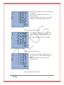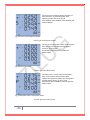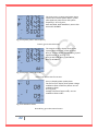
1
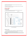
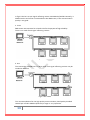
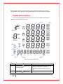
Universal Measuring Device User’s Manual 1 Please read this manual carefully before doing installation, operation and maintenance of ZMP meter. Following symbols are used in this user’s manual and on ZMP meter to alert the dangerous or to prompt in the operating or set process. Installation and maintenance of the ZMP meter should only be performed by qualified, competent personnel that have appropriate training and experience with high voltage and current device. The information contained in this document is believed to be accurate at the time of publication, however, Zilug assumes no responsibility for any errors which may appear here and reserves the right to make changes without notice. Please ask the local represent for latest product specifications before ordering. 2 Chapter 1 Introduction The purpose of ZMP The Application Area of ZMP The Function of ZMP ZMP Series 5 5 5 7 Chapter 2 Installation Appearance and Dimensions Installation Method 9 10 Chapter 3 Basic Operation and Setup Display panel and keys Metering data reading Statistics display Meter Parameter Setting Introduction of Measurement and Functions 17 18 26 29 39 Chapter 4 Communication Introducing Modbus Protocol Format of the communication Address table of ZMP 42 44 49 Appendix Appendix A Technical Data and Specification 3 58 Chapter 1 Introduction 4 The Purpose of ZMP Powerful Multifunction Power Meter ZMP Series Multifunction power meter was designed by used of latest microprocessor and digital signal process technology. Electric power parameters, energy and demand metering, power quality monitoring, remote control, statistics and records, all these functions are only in one pocket-size unit. It combines high accuracy measurement with intelligent multifunction and simple HMI interface. Ideal Choice for Electric Automation SCADA System ZMP can be used to replace all traditional electric meters. It also can be used as Remote Terminal Unit (RTU) for monitoring and controlling in a SCADA system. All the measured data is available via digital RS485 communication ports running the MobusTM protocol. Energy Management ZMP can measure double directions four quadrants kWh and kvarh with accuracy up to 0.5%. It can provide high standard energy data and energy demand data. All these data is important for statistics for each line feeder and total. The Application Area of ZMP Power Distribution Automation Intelligent Electric Switch Gear Industry Automation Building Automation Energy Manage System Large UPS System The Function of ZMP Multifunction, High Accuracy ZMP Series Intelligent power meter was designed by use of latest microprocessor and digital signal process technology. Electric power parameters metering, energy and demand recording, power quality monitoring, remote controlling, statistics and records, all these functions are only in one pocket size unit. Unbalance Factors, Demands and Pulse Output based on Energy or Reactive Energy in ZMP. It combines high accuracy measurement with intelligent multifunction and friendly HMI interface. 5 Small Size and Easy Installation W ith the size of DIN96 × 96 and 55mm depth after mounting, the ZMP can be installed in a small cabin. The fixing clips are used for easy installation and remove. Easy to Use By using of large screen high density LCD, the display of ZMP is easy to read and use. All the setting parameters can be access by using panel keys or communication port. The setting parameters are protected in Eprom, which will maintain its content after the meter is power off. W ith the backlight of the LCD, the display can be easily read in the dim environment. The back light “on” time is selectable. Multiple Wiring Modes In either high voltage or low voltage or three phase three wire or three phase four wire or single phase system, the ZMP can be easily used. 6 ZMP series The ZMP series products have two kinds of products, the standard ZMP and the advanced ZMP+. Both these two products have multiple choice. ZMP+ has the basic measuring function of ZMP. It also gets extra functions + Comparison of ZMP and ZMP ZMP ZMP+ Phase Voltage Function V1,V2,V3,Vlnavg Parameter √ √ Line Voltage V12,V23,V31,Vllavg √ √ Current I1,I2,I3,In,Iavg √ Natural Current In (direct with separate CT) Power P1,P2,P3,Psum √ Reactive Power Q1,Q2,Q3,Qsum √ √ Apparent Power S1,S2,S3,Ssum √ √ Power Factor PF1,PF2,PF3,PF √ √ Frequency Frequency √ √ Energy Ep_imp, Ep_exp, Ep_total, Ep_net √ √ Reactive Energy Eq_imp, Eq_exp, Eq_total, Eq_net √ √ Demand Dmd_P, Dmd_Q, Dmd_S √ √ Voltage Unbalance Factor U_unbl √ √ Current Unbalance Factor I_unbl √ √ Current THD Current Total Harmonic Distortion √ √ √ √ MAX with Time Stamp √ MIN with Time Stamp √ Pulse Output √ RS485 Port Modbus Protocol (RTU) √ √ Real Time Clock √ √ USB PORT √ √ Voltage and current sequence √ √ Table 1.2 Comparisons of ZMP and ZMP+ 7 Chapter 2 Installation 8 Appearance and Dimensions Appearance Figure2.1 Appearance of ZMP Part Name 1. Enclosure 2. Front Casing 3. LCD Display 4. Key 5.USB Port 9 Description The ZMP enclosure are made of high strength ant combustion engineering plastic After the installation, this part is before the panel. Large bright blue backlight LCD Display Four keys are used to select display and to set parameters of the meter Used data transfer and unit software upgrade Table2.1 Part name of ZMP Dimensions Fig.2.2Dimensions Installation Method Environmental Pleas e check the environment temperature and humidity to ensure the satisfaction of ZMP meter ’s requirement before the meter installation. Temperature Operation: -20oC to 70oC Storage: -40oC to 85oC Humidity 5% to 95% non-condensing ZMP meter should be installed in dry and dust free environment and avoid heat, radiation and high electrical noise source. Maximum Altitude: Site Requirement: Installation Steps 2,000m Indoor Use Normally, ZMP was installed on the panel of switch gear. 1. Firstly, cut a square hole on the panel of the switch gear. 90mm 90mm Fig.2.3 Panel cutting 10 2. Secondly, remove the clips from the meter and insert the meter into the square hole from the front side. 3. Finally, put clips back to the meter from the backside and push the clip tightly so that the meter is fixed on the panel. Wiring of ZMP Terminal Strips There are four group terminals on the back of ZMP, Voltages & Currents and RS485 Input Terminal, Auxiliary Power Terminal. Fig.2.4 wiring diagram Auxiliary Power The auxiliary power supply of the ZMP meter is 230Vac or 80-260V ac or dc (on ZMP+). Typical power consumption of the meter is less than 2W. A regulator or a UPS should be used when the power supply undulates. 11 A switch or circuit-breaker shall be included in the building installation, and it shall be in close proximity to the equipment and within easy reach of the operator, and it shall be marked as the disconnecting device for the equipment. A fuse (typical 1A/250Vac) should be used in auxiliary power supply loop. An isolated transformer or EMI filter should be used in the auxiliary power supply loop if there is power quality problem in the power supply. Voltage Input Two Voltage Input options are included in ZMP (100Vac and 400Vac). 100Vac is suitable for high or medium voltage system that the secondary of PT is 100Vac. 400Vac is suitable for low voltage system that less than 480Vac. The voltage input could be directly connected to the terminal of ZMP without the use of PT. The input line to line voltage should be less than 480Vac. If the input voltage is higher than 480Vac, the PT should be used. A fuse (typical 1A/250Vac) should be used in voltage input loop. PT should be used to transform the high voltage into measurement range of ZMP if it is used in high voltage system. The wire number of voltage input could be AW G16-12 or 1.3-2.0mm2 Current Input In a practical engineering application, CTs should be installed in the loop of measuring. Normally the secondary of CT is 5A. 1A is possible in ZMP. A CT of accuracy over 0.5% (rating over 3VA) is recommended and it will influence the measuring accuracy. The wire between CT and ZMP should be as shorter as possible. The length of the wire may increase the error of the measurement. CTs must be required if the rated current over 5A. The wire number of current input could be AWG15-10 or 1.5-2.5mm2 The CT loop should not be open circuit in any circumstance when the power is on. There should not be any fuse or switch in the CT loop and one end of the CT loop should be well connected to the ground. Vn Connection Vn is the reference point of ZMP voltage input. The lower is the wire resistance the less is the error. Three phase wiring diagram ZMP can satisfy almost all kinds of three phase wiring diagram. The current input wiring mode can be set separately in the meter parameter setting process. The current input wiring mode could be 3CT or 4CT. In 3CT wiring the natural current calculate from three phase currents and in 4CT wiring the natural current is measured from individual CT for natural line. 12 Voltage Input Wiring 3-Phase 4-Line Wye mode (3LN) the 3-Phase 4-Line Wye mode is popularly used in low voltage electric distribution power system. The power line can be connected to the meter voltage input directly. In the high voltage input system, 3PT Wye mode is often used. Current Input Wiring 3CT All the current input of three phase system can be looked as 3CT one, The current input mode of the ZMP should be set 3CT for this current input wiring mode. 4CT* All the current input of three phase system and natural line can be looked as 4 CT one, The current input mode of the ZMP should be set 4CT for this current input wiring mode to measure natural current directly. Communication The communication port and protocol of ZMP are RS485 and Modbus-RTU.The terminals of communication are A, B, S , +5V(as needed). A is differential signal +, B is differential signal - and S is connected to shield of twisted pair cable. Up to 32 devices can be connected on a RS485 bus. Use good quality shielded twisted pair cable, AW G22 (0.5mm2) or larger. The overall length of the RS485 cable connecting all devices cannot exceed 1200m (4000ft). ZMP is used as a slave device of master like PC, PLC, data collector or RTU. If the master does not have RS485 communication port, a converter has to be used. Normally a RS232/RS485 or USB/RS485 is adopted. The topology of RS485 net can be line, circle and star. 1. Line The connection from master to ZMP meter is one by one in the RS485 net as in fig 2.5. Fig 2.5 Line mode 13 In fig 2.5 the Rt is an anti signal reflecting resistor 120-300 ohm/0.25W. Normally, it added into the end of the circuit beside the last ZMP meter, if the communication quality is not good. 2. Circle ZMP meters are connected in a closed circle for the purpose of high reliability. There is no need of anti signal reflecting resistor. Fig 2.6 Circle mode 3. Star The connection of RS485 net is in Wye mode. Anti signal reflecting resistor may be needed in each line. Fig 2.7 Star mode The recommendations for the high quality communication, Good quality shielded twisted pair of cable AWG22 (0.6mm2) or larger is very important. 14 The shield of each segment of the RS485 cable must be connected to the ground at one end only. Keep communication cables away as much as possible from sources of electrical noise. Use RS232/RS485 or USB/RS485 converter with optical isolated output and surge protection. 15 Chapter 3 Basic Operation and Setup 16 Detail human-machine interface of the meter will be described in this chapter. This includes how to get the metering data and how to do the parameter setting. Display panel and keys There are one display panel and four keys in the front of ZMP. All the display segments are illustrated in fig 3.1. Fig 3.1 All Display Segments SN Display 1 Four lines of letter in the metering area 2 One line of 17 letter in the Description Display metering data voltage, current, power, power factor, frequency, demand, unbalance factor, max, min, etc. Energy data display or real time clock 3 4 5 6 7 8 9 10 11 energy area Load rate Display load current to rating current percentage Item label: Item label letter, MAX, U: voltage, I: current, P: power, q: MIN, Demand, PF, F reactive power, S: apparent power, PF: power factor, F: frequency, MAX: Maximum value, MIN: Minimum Value, Demand: Demand value, Avg: average value, I with N: neutral Current, PF, F, Avg and N indicate the fourth line data. Three phase unbalance label With letter U: voltage unbalance factor With letter I: Current unbalance factor Load characteristic Capacitor label: capacitive load Inductor label: inductive load Energy label imp: consumption energy exp: generating energy total: absolute sum of imp and exp energy net: algebraic sum Communication indicator No label: no communication One label: inquiry Two labels: inquiry and answer Energy pulse output indicator No label: no pulse output With label: pulse output Time label Time display in energy area Unit Indicate data unit Voltage: V, kV, Current: A, Power: kW and MW, Reactive Power: kvar and Mvar, Apparent Power: kVA and MVA, Frequency: Hz, Energy: kWh, Reactive energy: kvarh, Percentage: % Table 3.1 Display Panel description There are four delicacy keys labeled as H, P, E and V. Use these four keys to read metering data and do parameter setting. Metering data reading Normally, ZMP display the metering data, such as voltage, current, power etc. To read the metering data simply press the keys H, P, E and V. Press V to read voltage and current in the metering area. 18 The first screen: display Va, Vb, Vc and Ulnavg as in fig 3.2. V1=100.3V, V2=100.1V, V3=100.2V and Vlnavg=100.2V. Load rate is 50%, inductive load, imp energy is 8.8kwh, communication state normal, Fig 3.2 Three phase voltage Press V, go to the second screen. The second screen: display current of each phase and neutral, I1, I2, I3 and In as in fig 3.3. I1=2.498, I2=2.499, I3=2.491, In=0.008A. Fig 3.3 Three phase current Press V, go to the third screen. The third screen: display voltage of line to line, V12, V23, V31 and average Vllavg, as in fig 3.4 V12=173.2V, V23=173.3V, V31=173.1V, Vllavg=173.2V. Fig 3.4 Three phase to phase voltage Press V, go to the fourth screen. 19 The fourth screen: display current of each phase and average current as in fig 3.5, I1=2.498A, I2=2.499A, I3=2.491A, Iavg=2.496A. Fig 3.5 Three phase current Press V, go back to the first screen. Press P, display power related data. The first screen: display power of each phase P1, P2, P3 and system total power Psum. As in fig 3.6, P1=0.125kW, P2=0.125kW, P3=0.125kW, Ptot=0.375kW. Fig 3.6 Three phase power Press P, go to the second screen. The second screen, display reactive power of each phase, Q1, Q2, Q3 and system total reactive power Qsum. As in fig 3.7 Q1=0.217kvar, Q2=0.216kvar, Q3=0.216kvar and Qtot=0.649kvar Fig 3.7 Three phase reactive power Press P, go to the third screen. 20 The third screen: display apparent power of each phase S1, S2, S3 and system total apparent Power Stot As in fig 3.8 S1=0.250kVA, S2=0.250kVA, S3=0.249kVA and Stot=0.749kVA. Fig 3.8 Three phase apparent power Press P, go to the fourth screen. The fourth screen: power factor of each phase PF1, PF2, PF3 and system average power factor PF. As in fig 3.9, PF1=0.500, PF2=0.500, PF3=0.500 and PFtot=0.500. Fig 3.9 Three phase PF Press P, go to the fifth screen. The fifth screen: system total active power Ptot, system total reactive power Qtot, system total apparent power Stot and system average power factor. As in fig 3.10, Ptot=0.375, Qtot=0.649Kvar, Stot=0.749 and PFtot=0.500. Fig 3.10 System powers and power factor Press P, go to the sixth screen. 21 The sixth screen: system total power Psum, system total reactive power Qsum, system total apparent power Ssum and system frequency F. As in fig 3.11, Ptot=0.375kW, Qtot=0.649kvar, Stot=0.749 kVA and F=50.00Hz. Fig 3.11 System power and frequency Press P, go to seventh screen. The seventh screen: display three phase system power demand, power demand Dmd_P, reactive power demand Dmd_Q and apparent Dmd_S. As in fig 3.12, Dmd_P=0.375kW, Dmd_Q=0.649kvar, Dmd_S=0.749kVA. Fig 3.12 System power demand* Press P, go back to the first screen. Press H, display power quality data. The first screen: display three phase voltage unbalance factor and three phases current unbalance factor. As in fig 3.16, Voltage unbalance factor=0.8%, current unbalance factor=0.9%. Fig 3.13 Unbalance factor Press H key, go to the second screen. 22 The second screen: display three phase voltage and three phase current Sequence of wiring. As in fig 3.14 Press H , go back to the first screen. Fig 3.14 Sequence indicator Press E key: display energy and real time clock. The first screen: display the consumption energy Ep_imp=8.8kwh Fig 3.15 Import energy Press E key, go to the second screen. The second: Display the generation energy Eq_exp As in fig 3.16, Ep_exp=0.0kwh Fig 3.16 Export energy Press E key, go to the third screen. 23 The third screen: Display absolute sum of imp and exp energy Ep_total. As in fig 3.17, Ep_total=8.8kwh Fig 3.17 Total energy Press E key, go to the fourth screen. The fourth screen: Display algebraic sum of imp and exp energy Ep_net. As in fig 3.18, Ep_net=8.8kwh. Fig 3.18 Net energy Press E key, go to the fifth screen. The fifth screen: Display inductive reactive energy Eq_imp. As in fig 3.19, Eq_imp=15.2kvarh Fig 3.19 Inductive reactive energy Press E key, go to the sixth screen. 24 The sixth screen: Display the capacitive reactive energy Eq_exp. As in fig 3.20, Eq_exp=0.0kvarh. Fig 3.20 Capacitive reactive energy Press E key, go to the seventh screen. The seventh screen: display absolute sum of the reactive energy Eq_total. As in fig 3.21, Eq_total=15.2kvarh. Fig 3.21 Total reactive energy Press E key, go to the eighth screen. The eighth screen: Display algebraic sum of reactive energy. As in fig 3.22, Eq_net=15.2kvarh. Fig 3.22 Net reactive energy Press E key, go to the ninth screen. 25 The ninth screen: Display date. Format: YYYY: MM: DD As in fig 3.23, the date is Jan. 18, 2014 or can be in Hijri (SHAMSI) mode. Fig 3.23 Date Press E key, go to the tenth screen. The tenth screen: Display time. Format: HH: MM: SS. As in fig 3.24, the time is 13:20:29. Press E key, go back to the first screen. Fig 3.24 Time Statistics display* Press the P and V Keys simultaneously, the Max and Min value of metering data will display on the screen. The time stamp can be access through communication. Press the P and V keys simultaneously, go to the statistics screen. The first screen: Display the Max value of voltage. The Max label display on up right of letter U. As in fig 3.25, V1_max=100.3V, V2_max=100.1 and V3_max=100.2V. Fig 3.25 Max phase voltage 26 Press P key, to display the Min value of voltage. The Min label display on the low right of the letter U. Press P key again, go back to display the Max value of voltage. As in fig 3.26, V1_min=0.0V, V2_min=0.0V and V3_min=0.0V. Fig 3.26 Min phase voltage Press V key, go to the next screen. The second screen: Max value of the line to line voltage. As in fig 3.27, V12_max=173.2V, V23_max=173.3V and V31_max=173.1V Press P key to change display from Max to Min and vice versa. Fig 3.27 Max line voltage Press V key, go to the next screen. The third screen: Max value of the current. As in fig 3.28, I1_max=2.498A, I2_max=2.499A and I3_max=2.491A. Press P key to change display from Max to Min and vice versa. Fig 3.28 Max Current Press V key, go to the next screen. 27 The fourth screen: Max value of power and power factor. As In fig 3.29, Max value of system total power P_max=0.375W, Max value of system reactive power Q_max=0.649Kvar, Max value of system apparent power S_max=0.749kVA and Max value of system power factor PF_max=1.00. Press P key to change display from Max to Min and vice versa. Fig 3.29 Max value of system power Press V key, go to the next screen. The fifth screen: Max value of demand and frequency as in fig 3.30, Max value of system power demand Dmd_P_max=0.375kW, Max value of system reactive power demand Dmd_P_max=0.649kvar, Max value of system total apparent power demand Dmd_P_max=0.749kVA and Max value of system frequency. Press P key to change display from Max to Min and vice versa. Press V key, go to the next screen. Fig 3.30 Max value of demand & freq Note: Only ZMP+ has the function of Max and Min record function. 28 Meter Parameter Setting Under the metering data display mode, press the H and V key simultaneously, get into the meter parameter setting mode. In the meter parameter setting mode, press H key to move cursor. The digit that cursor is on it will be blink to show which digit going to change and Right move one digit each time. Press P for increasing and press E for decreasing. Press V for acknowledgment and going to the next setting item page. In any setting parameter if entered value is wrong the meter display Error message and will not save it. Press H and V page keys simultaneously to exit in any setting item page. Access code needed for going into the parameter setting mode. Only the person who knows the access code can do the parameter setting. The access code is 4 digits decimal number. It is from 0000 to 9999. The factory default is 0000. After key in the right access code, press V to go to the first parameter setting page, otherwise display Error message and go back to the metering data display page. As in fig 3.31 is access code page. Fig 3.31 Access code page The first screen: setting ZMP address page for the communication purpose. It is any digit number from 1 to 247. As in fig 3.32, the ZMP Address is 1. Changing method is simple, press H to move the cursor to the digit that need to be changed, press P for increasing and press E for decreasing. Press V for the acknowledgment Fig 3.32 Address setting page Note: Each meter on same RS485 net should have different address according to the Modbus-RTU protocol. 29 The second screen: Baud rate setting page the asynchronies communication setting of the ZMP is 8 data bit, no parity, 1 start bit and 1 stop bit. Baud rate could be one of the six, 1200, 2400, 4800, 9600, 19200, 38400. As in fig3.33, the baud rate of the ZMP is 19200bps. Press P or E to select one. Fig 3.33 Baud rate setting page Press V Key, go to the next page. The third screen: Current input wiring setting page. Current input wiring could be one of the two modes, 3CT and 4CT. (Refer to chapter 2) This item is available only on ZMP+. As in fig 3.34, current input mode setting is 3CT. Press P or E keys to select from 3CT and 4CT. Press V key for acknowledgment and going to the next setting page. Fig 3.34 Number of CT setting page The fourth screen: The interval time of between recordings of measured values on internal flash memory with time stamp. The interval can be set from 1 second to 900 second (15 minute). After time interval elapse it records below items: Date stamp, Time stamp, V1, V2, V3, V12, V23, V31 , I1, I2 ,I3 ,In ,P1 , P2, P3, Ptot, Q1, Q2, Q3, Qtot, S1, S2, S3, Stot, PF1, PF2, PF3, PFtot, Frequency. Fig 3.35 Interval time of records 30 The fifth screen: PT primary rating voltage PT_P setting page. PT_P value is an integer from 100 to 400,000. The unit is volt. As in fig 3.36, PT_P=100V, press P, E and H to change the value. Press V key for acknowledgment and going to the next setting page. Fig 3.36 PT primary setting page The sixth screen: PT secondary rating voltage PT_S setting page. PT_S value is an integer from 100 to 400. The unit is volt. As in fig 3.37, PT_S=100V, press P, E and H to change the value. Press V key for acknowledgment and going to the next setting page. Fig 3.37 PT secondary setting page Note: If there is no PT on the voltage input side of ZMP, the PT_P and PT_S should be set to same number (for example both of them set to 400) The seventh screen: CT primary rating current CT_P setting page. CT_P value is an integer from 5 to 8000. The unit is Amp. As in fig 3.38, CT_P=5A, pressing P, E and H keys to change the value. Press V key for acknowledgment and going to the next setting page. Fig 3.38 CT primary setting page 31 The eighth screen: CT secondary rating current CT_S setting page. CT_S value is 1A or 5A. The unit is Amp. As in fig 3.39, CT_S=5A, press P, E to change the value. Press V key for acknowledgment and going to the next setting page. Fig 3.39 CT secondary setting page The ninth screen: Setting speed of data transfer and type of created file on stick, ZMP has three different options for creating log file when inserting flash stick. Fig 3.40 Type of data transfer Long: in this type below header is created inside of text file, items separated with TAB to easy open by EXEL or other software to analyze. Transferring data from internal flash to USB stick take longer time in this type, but created file is complete and when the flash writing is ongoing you can use unit and perform other works. "YEAR, MONTH, DAY, HOUR, MINUTE, SECOND, I1, I2, I3, I_AVG, IN, V1, V2, V3, VPH_AVG, V12, V23, V31, VL_AVG, P1, P2, P3, PTOT, Q1, Q2, Q3, QTOT, S1, S2, S3, STOT, PF1, PF2, PF3, PFT, FREQUENCY, U_UNB, I_UNB”. Short: In this type below header is created inside of text file, some items is omitted in this type for increasing of data transfer speed, but the omitted items can be calculate with available items. For example user can calculate I_AVG by this formula: I_AVG = (I1+I2+I3)/3, This formula easily could be done by EXEL. Also like as above type you can use the unit during the transfer. "YEAR, MONTH, DAY, HOUR, MINUTE, SECOND, I1, I2, I3, IN, V1, V2, V3, P1, P2, P3, Q1, Q2, Q3, S1, S2, S3,PF1, PF2, PF3, FREQUENCY". 32 Short and Fast: the third type header is like Short but for more increasing of data transfer speed in this type you can’t use other functions of unit and the unit only focus to transfer data to USB stick. This type has fastest transfer speed. Note1: unit create a folder with name equal unit ID, then inside of this folder create a text file that its name is YY_MM_DD.TXT to display time of unit data reading. Note2: In ZMP+ another text file with the name of MIN_MAX.TXT that include recorded minimum and maximum values of parameters created. Note3: recorded parameters on unit transferred into a text file like a table on stick and arranged with time of occurrences. The tenth screen: Display unit ID setting page, User can define an individual ID for each unit, this ID used by unit to create folder on USB stick with this name. This option causes to user can easily manage files and folders that created on common stick by different units. Unit ID includes eight characters which could be selected from uppercase letters and numbers. As fig 3.41 ID of this unit is: ZILUG-10. Fig 3.41 Unit ID setting page The eleventh screen: Display type of logger setting page. You can define the way to unit record parameters on internal flash. If you select FIFO type after flash was full unit erases old ones and overwrites new ones, so you will access to recent measurement records when reading unit memory, and if select FILL AND HOLD the unit save items until to internal memory be full after that unit stop recording. Press V key for acknowledgment and going to the next setting page. Fig 3.42 Type of logger setting page 33 The twelfth screen: Display enable and disable of daylight saving. The RTC of unit can perform day light saving time automatically by setting this item to ON. Press V key for acknowledgment and going to the next setting page. Fig 3.43 Daylight saving setting page The thirteenth screen: Display the internal memory status. This page display the percent of used memory, if the whole of memory used the unit display FILL message and at bottom of LCD display the number of records. By pressing P or E key EREASE message appear and you can erase internal memory by pressing of V. To prevent unwanted format of memory after pressing of V you should enter access code. After memory format is finished, unit display MEM ERASED message. Fig 3.44 Internal memory status The fourteenth screen: Clearance of energy values. Select YES and press V key for clearing energy values and going to the next setting page. Fig 3.45 Energy values clear page 34 The fifteenth screen: Disable and enable of unit logger, select START and press V to run recording parameter and going to the next setting page. Fig 3.46 Logger starts and stop page The sixteenth screen: Display the type of date that unit used. Two types are selectable Georgian (MILADI) or Hijri (SHAMSI). Press V key for acknowledgment and going to the next setting page. Fig 3.47 Type of date setting page The seventeenth screen: Display back light “on” time setting page the backlight will go to “off” for the purpose of energy saving and component duration if the key does not be touched for a period time. The “on” time can be set from 1 to 15 Minute. As in fig 3.48, the setting time of the back light is 1 minute. The back light will automatically go to “off” if there is no touch on the keys in 1 minute. Fig 3.48 Backlight ON time 35 The eighteenth screen: Sliding window time of demand setting page. Sliding window time of demand is from 1 to 30 Minute. The window slid once per Minute. As in fig 3.49, the sliding window time is 5 Minute. Fig 3.49 Sliding window time The nineteenth screen: Clearance of the Max and Min value. The Max and Min statistics value can be cleared by operating the front keys. Clear means to begin record new Max and Min statistics value. As in fig 3.50, press E or P keys to select Yes or No. Yes: Clear the Max and Min statistics value No: Do not clear the Max and Min statistics value Press V key, go to the next setting page. Fig 3.50 Clearance of MAX and MIN The twentieth screen: System date setting page. Display format is YYYY: MM: DD For MILADI type: MM: 1 to 12 DD: 1 to 31 YYYY: 2014 to 2034 For SHAMSI type: MM: 1 to 12 DD: 1 to 31 YYYY: 1392 to 1412 As in fig 3.51, the setting date is Jan. 18, 2014. Fig 3.51 System date setting 36 The twenty first screen: system time setting page the display format is HH:MM:SS HH: 0 to 23 MM: 0 to 59 SS: 0 to 59 As in fig 3.52, the system time is 13:28:49 Press V key, go to next setting page. Fig 3.52 System time setting The twenty second screen: Access code setting page. The access code can be changed in this page. It is important to remember the new access code. As in fig 3.53, the access code is 0000. Press the V key and let the access code be stored in ZMP. Fig 3.53 Access code setting The twenty third screen: Calibration of unit. Through this page you can re-calibrate of unit. These processes can be done in two ways SIMPLE and ADVANCED. The SIMPLE process have less complicity and can be done fast but ADVANCED is more accurate and need more time. For entering calibration menu you need access code that differs from original access code. You need multifunction calibrator to do it. Fig 3.54 Recalibrate of unit 37 The twenty fourth screen: Update of unit software through USB port. The company releases new software for upgrade and solve of unit problems as needed. You can get these updates file from company web page or by email. Update files name are in format of AKUPXXXX.ENC that XXXX shows version of update file. Fig 3.55 Unit software upgrade page For upgrade you should done below steps: 1. Copy update file to flash stick. 2. Go to setting menu by pressing H and V buttons simultaneously 3. Go to twenty fourth screen page 4. Now insert stick to USB port 5. Unit display current version of unit software and version of software on stick memory 6. In this step if you press V button you accept to do update process and otherwise you can exit by pressing H and V button simultaneously. 7. If you press V key unit check update file on stick and if it was true unit start updating process. 8. Wait to finish this process and restart of unit. 38 Introduction of Measurement and Functions Almost all electric parameters in power systems can be measured by ZMP series intelligent power meter. Some parameters that do not be familiar by users will be introduced in this part. Voltage (V): True RMS value of three phase voltages, three line to line voltages and their average are measured and displayed in ZMP. Current (I): True RMS value of three phase currents, neutral current and their average are measured and displayed in ZMP. Power (P): Three phase power and system total power are measured and display in ZMP. Reactive power (Q): Three phase reactive power and system total reactive power are measured and displayed in ZMP. Apparent power (S): Three phase apparent power and system total apparent power are measured and displayed in ZMP. Frequency (F): The frequency of V1 phase voltage input is measured as system frequency. Energy (kWh): Energy is time integral of power. The unit is kWh. As power has direction, positive means consumption and negative means generating. So the energy has also the nature of consumption or generating. Import (imp): Consumption energy Export (exp): Generating energy Total: Absolute sum of import and export energy Net: Algebraic sum of import and export energy Reactive Energy (kvarh): Reactive energy is time integral of reactive power. The unit is kvarh. As reactive power has direction, positive means inductive and negative means capacitive, so the reactive energy has also got the nature of inductive and capacitive. Import (imp): Inductive reactive energy Export (exp): Capacitive reactive energy Total: Absolute sum of import and export reactive energy Net: Algebraic sum of import and export reactive energy Each of the four reactive energies is measured and stored independently. 39 Demand*: Demand of power, reactive power and apparent power. The demand statistics method in ZMP+ is sliding window. The sliding window time can be choosing between 1 to 30 minutes. The window slides one minute each time. For example, the sliding window time is supposed to be 3 minute. If average power of the first Minute is 12, average power of the second minute is 14 and average power of the third minute is 10, then the total demand of the 3 minutes is (12+14+10)/3=12 at the end of the three minute. If another minute passed, the average power of the minute is 8, then the total power demand of the last three minute is (14+10+8)/3=10 at the end of the fourth minute. Three phase unbalance factor: three phase voltage unbalance factor and three phase current unbalance factor can be measured in ZMP+. The unbalance factor is express in percentage. Voltage unbalance factor = Current unbalance factor = 𝑇𝑇ℎ𝑒𝑒 𝑀𝑀𝑀𝑀𝑀𝑀 𝑑𝑑𝑑𝑑𝑑𝑑𝑑𝑑𝑑𝑑𝑑𝑑𝑑𝑑𝑑𝑑𝑑𝑑 𝑣𝑣𝑣𝑣𝑣𝑣𝑣𝑣𝑣𝑣 𝑜𝑜𝑜𝑜 𝑡𝑡ℎ𝑟𝑟𝑟𝑟𝑟𝑟 𝑣𝑣𝑣𝑣𝑣𝑣𝑣𝑣𝑣𝑣𝑣𝑣𝑣𝑣𝑣𝑣 𝐴𝐴𝐴𝐴𝐴𝐴𝐴𝐴𝐴𝐴𝐴𝐴𝐴𝐴 𝑣𝑣𝑣𝑣𝑣𝑣𝑣𝑣𝑣𝑣 𝑜𝑜𝑜𝑜 𝑡𝑡ℎ𝑟𝑟𝑟𝑟𝑟𝑟 𝑣𝑣𝑣𝑣𝑣𝑣𝑣𝑣𝑣𝑣𝑣𝑣𝑣𝑣𝑣𝑣 𝑇𝑇ℎ𝑒𝑒 𝑀𝑀𝑀𝑀𝑀𝑀 𝑑𝑑𝑑𝑑𝑑𝑑𝑑𝑑𝑑𝑑𝑑𝑑𝑑𝑑𝑑𝑑𝑑𝑑 𝑣𝑣𝑣𝑣𝑣𝑣𝑣𝑣𝑣𝑣 𝑜𝑜𝑜𝑜 𝑡𝑡ℎ𝑟𝑟𝑟𝑟𝑟𝑟 𝑐𝑐𝑐𝑐𝑐𝑐𝑐𝑐𝑐𝑐𝑐𝑐𝑐𝑐𝑐𝑐 𝐴𝐴𝐴𝐴𝐴𝐴𝐴𝐴𝐴𝐴𝐴𝐴𝐴𝐴 𝑣𝑣𝑣𝑣𝑙𝑙𝑙𝑙𝑙𝑙 𝑜𝑜𝑜𝑜 𝑡𝑡ℎ𝑟𝑟𝑟𝑟𝑟𝑟 𝑐𝑐𝑐𝑐𝑐𝑐𝑐𝑐𝑐𝑐𝑐𝑐𝑐𝑐𝑐𝑐 Max/Min statistics*: The maximum and minimum value of the metering data is stored in NV-RAM and can be accessed or cleared from front panel or through communication in ZMP+. These metering data are phase voltage, line to line voltage, current, power, reactive power, apparent power, power factor, frequency, demand. Real time clock: There is a real time clock in the ZMP. The date, month, year, hour, minute and second can be read or set from front panel or through communication. 40 Chapter 4 Communication 41 Introducing Modbus Protocol The Modbus RTU protocol is used for communication in ZMP. The data format and error check method is defined in Modbus protocol. The half duplex query and respond mode is adopted in Modbus protocol. There is only one master device in the communication net. The others are slave devices, waiting for the query of the master. Transmission mode The mode of transmission defines the data structure within a frame and the rules used to transmit data. The mode is defined in the following which is compatible with Modbus RTU Mode*. Coding System Start bit Data bits Parity Stop bit Error checking 8-bit binary 1 8 no parity 1 CRC check *Modbus is trademark of Modicon, Inc. Framing Address 8-Bits Function Data 8-Bits N x 8-Bits Table4.1 Data Frame Format Check 16-Bits Address Field The address field of a message frame contains eight bits. Valid slave device addresses are in the range of 1~247 decimal. A master addresses a slave by placing the slave address in the address field of the message. When the slave sends its response, it places its own address in this address field of the response to let the master know which slave is responding. Function Field The function code field of a message frame contains eight bits. Valid codes are in the range of 1~255 decimal. When a message is sent from a master to a slave device the function code field tells the slave what kind of action to perform. 42 Code 0x03 0x04 0x06 0x10 Meaning Read Holding Registers Action Obtain current binary value in one or more registers Read Input Registers Obtain logged values from internal flash memory Write Single Register Place specific binary values into a register Write Multiple registers Place specific binary values into a series of consecutive Multiple-Registers Table 4.2 Function Code Data Field The data field is constructed using sets of two hexadecimal digits, in the range of 0x00 to 0xFF hexadecimal. The data field of messages sent from a master to slave devices contains additional information which the slave must use to take the action defined by the function code. This can include items like discrete and register addresses, the quantity of items to be handled, and the count of actual data bytes in the field. For example, if the master requests a slave to read a group of holding registers (function code 03), the data field specifies the starting register and how many registers are to be read. If the master writes to a group of registers in the slave (function code 0x10 hexadecimal), the data field specifies the starting register, how many registers to write, the count of data bytes to follow in the data field, and the data to be written into the registers. If no error occurs, the data field of a response from a slave to a master contains the data requested. If an error occurs, the field contains an exception code that the master application can use to determine the next action to be taken. The data field can be nonexistent (of zero length) in certain kinds of messages. Error Check Field Messages include an error’s checking field that is based on a Cyclical Redundancy Check (CRC) method. The CRC field checks the contents of the entire message. It is applied regardless of any parity check method used for the individual characters of the message. The CRC field is two bytes, containing a 16bit binary value. The CRC value is calculated by the transmitting device, which appends the CRC to the message. The receiving device recalculates a CRC during receipt of the message, and compares the calculated value to the actual value it received in the CRC field If the two values are not equal, an error results. The CRC is started by first preloading a 16-bit register to all 1’s. Then a process begins of applying successive 8-bit bytes of the message to the current contents of the register. Only the eight bits of data in each character are used for generating the CRC. Start and stop bits, and the parity bit, do not apply to the CRC. During generation of the CRC, each 8-bit character is exclusive ORed with the register contents. Then the result is shifted in the direction of the least significant bit (LSB), with a zero filled into the most significant bit (MSB) position. The LSB is extracted and examined. If the LSB was a1, the register is then exclusive ORed with a reset, fixed value. 43 If the LSB was a0, no exclusive OR takes place. This process is repeated until eight shifts have been performed. After the last (eighth) shift, the next 8-bit byte is exclusive ORed with the register current value, and the process repeats for eight more shifts as described above. The final contents of the register, after all the bytes of the message have been applied, is the CRC value. When the CRC is appended to the message, the low-order byte is appended first, followed by the high-order byte. Format of the communication No. of Registers Hi No. of Registers Lo CRC Lo CRC Hi 0x03 Starting Address Lo Function 0x01 Starting Address Hi Slave address Explanation of frame 0x00 0x01 0x00 0x21 0x84 0x65 Table 4.3 Explanation of frame In table 4.3, the meaning of each abbreviated word is: Slave Address: Address of slave device Function: Function code Starting Address Hi: start register address high byte Starting Address Lo: start register address low byte No. of Registers Hi: number of register high byte No. of Registers Lo: number of register low byte CRC16 hi: CRC high byte CRC16 lo: CRC low byte 44 3 Read Holding Registers (Function Code 0x03) Starting Address Hi Starting Address Lo No. of Registers Hi No. of Registers Lo CRC Lo CRC Hi 0x01 Function Slave address Query This function allows the master to obtain the measurement results of ZMP. Table 4.4 is an example to read the 3 measured data (Va, Vb and Vc) from slave device number 1, the data address of V1 is 0x01H, V2 is 0x02H and V3 is 0x03H. 0x03 0x00 0x01 0x00 0x03 0x54 0x0B Table 4.4 Read V1, V2, V3 Query Message Register value Lo Register value Hi Register value Lo CRC Lo CRC Hi 0x06 Register value Hi Byte Count 0x03 Register value Lo Function 0x01 Register value Hi Slave address Response The ZMP response includes the ZMP address, function code, quantity of data byte, data, and error checking. An example response to read V1, V2 and V3 is: V1=0x07CBH (199.5V), V2=0x07CAH (199.4V), V3=0x07CAH (199.4V) is shown as Table4.5. 0x07 0xCB 0x07 0xCA 0x07 0xCA 0x54 0x0B Table4.5 Read V1, V2 and V3 Message 45 4 Read Input Registers (Function Code 0x04) Page Address Hi Page Address Lo Quantity of Input Reg. Hi Quantity of Input Reg. Lo CRC Lo CRC Hi 0x01 Function Slave address Query This function allows the master to obtain the logged values from internal flash. Master by every request query can read one page that includes four recorded values. Table 4.6 is an example to read second page from slave device number 1. 0x04 0x00 0x02 0x00 0x6E 0x0A 0x92 Table 4.6 Read second page of internal flash Byte 2 0x-- 0x-- CRC Hi Byte 1 0xDC CRC Lo Byte Count 0x04 Byte 220 Function 0x01 ……… Slave address Response The ZMP response includes the ZMP address, function code, quantity of data byte, data, and error checking. 0x-- 0x-- 0x-- Table 4.7 Transfer 220 byte of page2 of internal flash 46 6 Write Single Register (Function Code 0x06) Slave address Function Register Address Hi Register Address Lo Registers Value Hi Registers Value Lo CRC Lo CRC Hi Query Function 0x06 allows the user to modify the contents of one Register. Any Register that exists within the ZMP writable memory can have its contents changed by this message. The example below is a request to a ZMP number 1 to Preset CT primary to 1250, while its Hex Value 0x04E2H. CT_P data address is 0x0190H. 0x01 0x06 0x01 0x90 0x04 0xE2 0x0A 0x92 Table 4.8 Preset CT_P Slave address Function Register Address Hi Register Address Lo Registers Value Hi Registers Value Lo CRC Lo CRC Hi Response The normal response is an echo of the request, returned after the register contents have been written. 0x01 0x06 0x01 0x90 0x04 0xE2 0x0A 0x92 Table 4.9 writes single register Response Message 47 16 Write Multiple Registers (Function Code 0x10) CRC Hi 0xE2 CRC Lo Registers Value Lo 0x04 Registers Value Hi Quantity of Registers Hi 0x90 Registers Value Lo Starting Address Lo 0x01 Registers Value Hi Starting Address Hi 0x10 Byte Count Function 0x01 Quantity of Registers Lo Slave address Query Function 0x10 allows the user to modify the contents of Multi-Register. Any Register that exists within the ZMP writable memory can have its contents changed by this message. The example below is a request to a ZMP number 1 to Preset CT primary to 1250, while its Hex Value 0x04E2H. CT_P data address is 0x0190H. 0x0A 0x92 Table 4.10 Preset CT_P Slave address Function Starting Address Hi Starting Address Lo Quantity of Registers Hi Quantity of Registers Lo CRC Lo CRC Hi Response The normal response is an echo of the request, returned after the register contents have been written. 0x01 0x10 0x01 0x90 0x04 0xE2 0x0A 0x92 Table 4.11 writes single register Response Message 48 Address table of ZMP Basic Analog measurements Address Parameter 0x0000 0x0001 0x0002 0x0003 0x0004 0x0005 0x0006 0x0007 0x0008 0x0009 0x000A 0x000B 0x000C 0x000D 0x000E 0x000F 0x0010 0x0011 0x0012 0x0013 0x0014 0x0015 0x0016 0x0017 0x0018 0x0019 0x001A 0x001B 0x001C 0x001D 0x001E 0x001F 0x0020 0x0021 0x0022 0x0023 0x0024 0x0025 0x0026 0x0027 0x0028 0x0029 0x002A 0x002B 0x002C 0x002D 0x002E 0x002F 0x0030 0x0031 0x0032 Frequency (F) Phase Voltage V1 Phase Voltage V2 Phase Voltage V3 Average Phase Voltage Vlnavg Line Voltage V12 Line Voltage V23 Line Voltage V31 Average Line Voltage Vllavg Current I1 Current I2 Current I3 Average Current Iavg Neutral Line Current In Phase Power P1 Phase Power P2 Phase Power P3 System Power Ptot Phase Reactive Power Q1 Phase Reactive Power Q2 Phase Reactive Power Q3 System Reactive Power Qtot Phase Apparent Power S1 Phase Apparent Power S2 Phase Apparent Power S3 System Apparent Power Stot Phase Power Factor PF1 Phase Power Factor PF2 Phase Power Factor PF3 System Power Factor PFtot Voltage Unbalance Factor U_unbl Current Unbalance Factor I_unbl Load Type RT (L/C/R) Power Demand Dmd_Ptot Reactive power Demand Dmd_Qtot Apparent Power Demand Dmd_Stot Import Energy Ep_imp (hi word) Import Energy Ep_imp (lo word) Export Energy Ep_exp (hi word) Export Energy Ep_exp (lo word) Import Reactive Energy Eq_imp (hi word) Import Reactive Energy Eq_imp (lo word) Export Reactive Energy Eq_exp (hi word) Export Reactive Energy Eq_exp (lo word) Absolute Sum of Energy Ep_total (hi word) Absolute Sum of Energy Ep_total (lo word) Algebra Sum of Energy Ep_net (hi word) Algebra Sum of Energy Ep_net (lo word) Absolute Sum of Energy Eq_total (hi word) Absolute Sum of Energy Eq_total (lo word) Algebra Sum of Energy Eq_net (hi word) 49 Range Object Type 4500~6500 0~65535 0~65535 0~65535 0~65535 0~65535 0~65535 0~65535 0~65535 0~65535 0~65535 0~65535 0~65535 0~65535 -32768~32767 -32768~32767 -32768~32767 -32768~32767 -32768~32767 -32768~32767 -32768~32767 -32768~32767 0~65535 0~65535 0~65535 0~65535 -1000~1000 -1000~1000 -1000~1000 -1000~1000 0~3000 0~3000 76/67/82 -32768~32767 -32768~32767 0~65535 0~999999999 word word word word word word word word word word word word word word word word word word word word word word word word word word word word word word word word word word word word Double word Double word Double word Double word Double word Double word Double word Double 0~999999999 0~999999999 0~999999999 0~999999999 0~999999999 0~999999999 0~999999999 Type of access R R R R R R R R R R R R R R R R R R R R R R R R R R R R R R R R R R R R R R R R R R R R R R R R R R R 0x0033 0x0034 0x0035 0x0036 0x0037 0x0038 0x0039 0x003A 0x003B 0x003C 0x003D 0x003E 0x003F 0x0040 0x0041 0x0042 0x0043 0x0044 0x0045 0x0046 0x0047 0x0048 0x0049 0x004A 0x004B 0x004C 0x004D 0x004E 0x004F 0x0050 0x0051 0x0052 0x0053 0x0054 0x0055 0x0056 0x0057 0x0058 0x0059 0x005A 0x005B 0x005C 0x005D 0x005E 0x005F 0x0060 0x0061 0x0062 0x0063 0x0064 0x0065 0x0066 0x0067 0x0068 0x0069 0x006A Algebra Sum of Energy Eq_net (lo word) Maximum Records* V1_max Time Stamp of Va_max year month day hour minute second V2_max Time Stamp of Vb_max year month day hour minute second V3_max Time Stamp of Vc_max year month day hour minute second V12_max Time Stamp of Vab_max year month day hour minute second V23_max Time Stamp of Vbc_max year month day hour minute second V31_max Time Stamp of Vca_max year month day hour minute second I1_max Time Stamp of Ia_max year month day hour minute second I2_max Time Stamp of Ib_max year month day hour minute 50 0~65535 2014~2034 or 1392~1412 1~12 1~31 0~23 0~59 0~59 0~65535 2014~2034 or 1392~1412 1~12 1~31 0~23 0~59 0~59 0~65535 2014~2034 or 1392~1412 1~12 1~31 0~23 0~59 0~59 0~65535 2014~2034 or 1392~1412 1~12 1~31 0~23 0~59 0~59 0~65535 2014~2034 or 1392~1412 1~12 1~31 0~23 0~59 0~59 0~65535 2014~2034 or 1392~1412 1~12 1~31 0~23 0~59 0~59 0~65535 2014~2034 or 1392~1412 1~12 1~31 0~23 0~59 0~59 0~65535 2014~2034 or 1392~1412 1~12 1~31 0~23 0~59 word R word word word word word word word word word word word word word word word word word word word word word word word word word word word word word word word word word word word word word word word word word word word word word word word word word word word word word word word R R R R R R R R R R R R R R R R R R R R R R R R R R R R R R R R R R R R R R R R R R R R R R R R R R R R R R R 0x006B 0x006C 0x006D 0x006E 0x006F 0x0070 0x0071 0x0072 0x0073 0x0074 0x0075 0x0076 0x0077 0x0078 0x0079 0x007A 0x007B 0x007C 0x007D 0x007E 0x007F 0x0080 0x0081 0x0082 0x0083 0x0084 0x0085 0x0086 0x0087 0x0088 0x0089 0x008A 0x008B 0x008C 0x008D 0x008E 0x008F 0x0090 0x0091 0x0092 0x0093 0x0094 0x0095 0x0096 0x0097 0x0098 0x0099 0x009A 0x009B 0x009C 0x009D 0x009E 0x009F 0x00A0 0x00A1 0x00A2 0x00A3 I3_max Time Stamp of Ic_max Ptot_max Time Stamp of Ptot_max Qtot_max Time Stamp of Qtot_max Stot_max Time Stamp of Stot_max PFtot_max Time Stamp of PFtot_max Fr_max Time Stamp of Fr_max Dmd_Ptot_max Time Stamp of Dmd_Ptot_max Dmd_Qtot_max Time Stamp of Dmd_Qtot_max 51 second 0~59 0~65535 year month day hour minute second 2014~2034 or 1392~1412 year month day hour minute second 2014~2034 or 1392~1412 year month day hour minute second 2014~2034 or 1392~1412 year month day hour minute second 2014~2034 or 1392~1412 year month day hour minute second 2014~2034 or 1392~1412 year month day hour minute second 1~12 1~31 0~23 0~59 0~59 -32768~32767 1~12 1~31 0~23 0~59 0~59 -32768~32767 1~12 1~31 0~23 0~59 0~59 0~65535 1~12 1~31 0~23 0~59 0~59 -1000~1000 1~12 1~31 0~23 0~59 0~59 4500~6500 2000~2099 1~12 1~31 0~23 0~59 0~59 -32768~32767 year month day hour minute second 2014~2034 or 1392~1412 year month day hour minute second 2014~2034 or 1392~1412 1~12 1~31 0~23 0~59 0~59 -32768~32767 1~12 1~31 0~23 0~59 0~59 word word word word word word word word word word word word word word word word word word word word word word word word word word word word word word word word word word word word word word word word word word word word word word word word word word word word word word word word word R R R R R R R R R R R R R R R R R R R R R R R R R R R R R R R R R R R R R R R R R R R R R R R R R R R R R R R R R 0x00A4 0x00A5 0x00A6 0x00A7 0x00A8 0x00A9 0x00AA Dmd_Stot_max Time Stamp of Dmd_Stot_max 0x00AB 0x00AC 0x00AD 0x00AE 0x00AF 0x00B0 0x00B1 0x00B2 0x00B3 0x00B4 0x00B5 0x00B6 0x00B7 0x00B8 0x00B9 0x00BA 0x00BB 0x00BC 0x00BD 0x00BE 0x00BF 0x00C0 0x00C1 0x00C2 0x00C3 0x00C4 0x00C5 0x00C6 0x00C7 0x00C8 0x00C9 0x00CA 0x00CB 0x00CC 0x00CD 0x00CE 0x00CF 0x00D0 0x00D1 0x00D2 0x00D3 0x00D4 0x00D5 0x00D6 0x00D7 0x00D8 0x00D9 0x00DA 0x00DB V1_min Time Stamp of Va_min V2_min Time Stamp of Vb_min V3_min Time Stamp of Vc_min V12_min Time Stamp of Vab_min V23_min Time Stamp of Vbc_min V31_min Time Stamp of Vca_min I1_min Time Stamp of Ia_min 52 0~65535 year month day hour minute second Minimum Records* 2014~2034 or 1392~1412 year month day hour minute second 2014~2034 or 1392~1412 year month day hour minute second 2014~2034 or 1392~1412 year month day hour minute second 2014~2034 or 1392~1412 year month day hour minute second 2014~2034 or 1392~1412 year month day hour minute second 2014~2034 or 1392~1412 year month day hour minute second 2014~2034 or 1392~1412 year month day hour minute second 2014~2034 or 1392~1412 1~12 1~31 0~23 0~59 0~59 0~65535 1~12 1~31 0~23 0~59 0~59 0~65535 1~12 1~31 0~23 0~59 0~59 0~65535 1~12 1~31 0~23 0~59 0~59 0~65535 1~12 1~31 0~23 0~59 0~59 0~65535 1~12 1~31 0~23 0~59 0~59 0~65535 1~12 1~31 0~23 0~59 0~59 0~65535 1~12 1~31 0~23 0~59 0~59 word word word word word word word R R R R R R R word word word word word word word word word word word word word word word word word word word word word word word word word word word word word word word word word word word word word word word word word word word word word word word word word R R R R R R R R R R R R R R R R R R R R R R R R R R R R R R R R R R R R R R R R R R R R R R R R R 0x00DC 0x00DD 0x00DE 0x00DF 0x00E0 0x00E1 0x00E2 0x00E3 0x00E4 0x00E5 0x00E6 0x00E7 0x00E8 0x00E9 0x00EA 0x00EB 0x00EC 0x00ED 0x00EE 0x00EF 0x00F0 0x00F1 0x00F2 0x00F3 0x00F4 0x00F5 0x00F6 0x00F7 0x00F8 0x00F9 0x00FA 0x00FB 0x00FC 0x00FD 0x00FE 0x00FF 0x0100 0x0101 0x0102 0x0103 0x0104 0x0105 0x0106 0x0107 0x0108 0x0109 0x010A 0x010B 0x010C 0x010D 0x010E 0x010F 0x0110 0x0111 0x0112 0x0113 0x0114 I2_min Time Stamp of Ib_min I3_min Time Stamp of Ic_min Ptot_min Time Stamp of Ptot_min Qtot_min Time Stamp of Qtot_min Stot_min Time Stamp of Stot_min PFtot_min Time Stamp of PFtot_min Fr_min Time Stamp of Fr_min Dmd_Ptot_min Time Stamp of Dmd_Ptot_min Dmd_Qtot_min 53 0~65535 year month day hour minute second 2014~2034 or 1392~1412 year month day hour minute second 2014~2034 or 1392~1412 year month day hour minute second 2014~2034 or 1392~1412 year month day hour minute second 2014~2034 or 1392~1412 year month day hour minute second 2014~2034 or 1392~1412 year month day hour minute second 2014~2034 or 1392~1412 year month day hour minute second 2014~2034 or 1392~1412 year month day hour minute second 2014~2034 or 1392~1412 1~12 1~31 0~23 0~59 0~59 0~65535 1~12 1~31 0~23 0~59 0~59 -32768~32767 1~12 1~31 0~23 0~59 0~59 -32768~32767 1~12 1~31 0~23 0~59 0~59 0~65535 1~12 1~31 0~23 0~59 0~59 -1000~1000 1~12 1~31 0~23 0~59 0~59 4500~6500 1~12 1~31 0~23 0~59 0~59 -32768~32767 1~12 1~31 0~23 0~59 0~59 -32768~32767 word word word word word word word word word word word word word word word word word word word word word word word word word word word word word word word word word word word word word word word word word word word word word word word word word word word word word word word word word R R R R R R R R R R R R R R R R R R R R R R R R R R R R R R R R R R R R R R R R R R R R R R R R R R R R R R R R R 0x0115 0x0116 0x0117 0x0118 0x0119 0x011A 0x011B 0x011C 0x011D 0x011E 0x011F 0x0120 0x0121 0x0122 0x0123 0x0124 0x0125 0x0126 0x0127 0x0128 0x0129 0x012A 0x012B 0x012C 0x012D 0x012E 0x012F 0x0130 0x0131 0x0132 0x0133 0x0134 0x0135 0x0136 0x0137 0x0138 0x0139 0x013A 0x013B 0x013C 0x013D 0x013E 0x013F 0x0140 0x0141 0x0142 0x0143 0x0144 0x0145 0x0146 0x0147 0x0148 0x0149 0x014A 0x014B Time Stamp of Dmd_Qtot_min year month day hour minute second Dmd_Stot_min Time Stamp of Dmd_Stot_min year month day hour minute second Phase B (phase angle between Voltage B and Voltage A) Phase C (phase angle between Voltage C and Voltage A) Temperature (1°C resolution) Firmware version Current page number Internal flash memory overflow (overflow occure:1) Main password Calibration password Slave address Baud rate (1200-2400-4800-9600-19200-38400bps) Number of ct PT primary (hi word) PT primary (lo word) PT secondary CT primary CT secondary Light time for LCD backlight (minute) Slide time for demand measuring (minute) Sample time for logging (second) Type of date (shamsi:0 and miladi:1) Type of logging ( FIFO:0 and FILL and HOLD:1) Status of logger (START: 1 and STOP: 0) Time out value for Modbus communication (ms) Year Month Day Hour Minute Second Unit ID letter(8) Unit ID letter(7) Unit ID letter(6) Unit ID letter(5) Unit ID letter(4) Unit ID letter(3) Unit ID letter(2) Unit ID letter(1) Type of reading logged file(shortandfast:0 – short:1 -long:2) USB port status (not available:0 available:1) Internal flash status (not available:0 available:1) RTC status (not available:0 available:1) Flash stick status (not available:0 available:1 saving:2 saved:3 no data:4) 2014~2034 or 1392~1412 1~12 1~31 0~23 0~59 0~59 0~65535 2014~2034 or 1392~1412 1~12 1~31 0~23 0~59 0~59 0~360 0~360 0~100 0001~9999 0~65535 0~1 0000~9999 0000~9999 1~247 1200~38400 3~4 100~400000 100~400 5~8000 1 or 5 0~120 1~30 1~900 0 or 1 0 or 1 0 or 1 20~2500 2014~2034 or 1392~1412 1~12 1~31 0~23 0~59 0~59 A~Z and 0~9 A~Z and 0~9 A~Z and 0~9 A~Z and 0~9 A~Z and 0~9 A~Z and 0~9 A~Z and 0~9 A~Z and 0~9 0 or 1 or 2 0 or 1 0 or 1 0 or 1 0~4 Table 4.12 Metering data address table 54 word word word word word word word word word word word word word word word word word word word word word word word word Double word word word word word word word word word word word word word word word word word word word word word word word word word word word word word word R R R R R R R R R R R R R R R R R R R R/W R/W R/W R/W R/W R/W R/W R/W R/W R/W R/W R/W R/W R/W R/W R/W R/W R/W R/W R/W R/W R/W R/W R/W R/W R/W R/W R/W R/W R/W R/W R/W R/W R/W R/W The Relationship between numerical value in register of ZMP and the real physical value is as following table. (Rx is the numerical value in register of ZMP) Parameter Relationship Unit V1, V2, V3, V12, V23, V31, Vllavg, Vlnavg I1, I2, I3, Iavg, In P1, P2, P3, Ptot, Dmd_Ptot Q1, Q2, Q3, Qtot, Dmd_Qtot S1, S2, S3, Stot, Dmd_Stot PF1, PF2, PF3, PFtot Frequency Load Type (L/C/R) U_unbl, I_unbl Energy Ep_imp, Ep_exp, Ep_total, Ep_net Reactive Energy Eq_imp, Eq_exp, Eq_total, Eq_net THD U = Rx×(PT_P/PT_S)/10 Volt(V) I = Rx × (CTP/CT_S)/1000 P = Rx × (PT_P/PT_S)×(CT_P/ CT_S) Q = Rx × (PT_P/PT_S)×(CT_P/ CT_S) S = Rx × (PT_P/PT_S)×(CT_P/ CT_S) PF = Rx/1000 F = Rx/100 ASCII of L, C, R Unbl = (Rx/1000)×100% Ep = Rx / 10 Eq = Rx / 10 THD=Rx / 10000×100% Table 4.13 Measuring data convert table 55 Amp(A) Watt(W) Var VA NA Hz NA % Kwh Kvarh NA Each Page of internal flash memory includes four records. By per query of Modbus function code 0x04 we can read one page from internal memory of logged values. Below table show arrange of measured values that recorded in one page of flash memory. First record Second record Third record Fourth record Year(hi byte) Year(lo byte) Month Day Hour Minute Second I1(hi byte) I1(lo byte) I2(hi byte) I2(lo byte) I3(hi byte) I3(lo byte) In(hi byte) In(lo byte) V1(hi byte) V1(lo byte) V2(hi byte) V2(lo byte) V3(hi byte) V3(lo byte) P1(hi byte) P1(lo byte) P2(hi byte) P2(lo byte) P3(hi byte) P3(lo byte) Ptot(hi byte) Ptot(lo byte) Q1(hi byte) Q1(lo byte) Q2(hi byte) Q2(lo byte) Q3(hi byte) Q3(lo byte) Qtot(hi byte) Qtot(lo byte) S1(hi byte) S1(lo byte) S2(hi byte) S2(lo byte) S3(hi byte) S3(lo byte) Stot(hi byte) Stot(lo byte) PF1(hi byte) PF1(lo byte) PF2(hi byte) PF2(lo byte) PF3(hi byte) PF3(lo byte) PFtot(hi byte) PFtot(lo byte) Fr(hi byte) Fr(lo byte) Year(hi byte) Year(lo byte) Month Day Hour Minute Second I1(hi byte) I1(lo byte) I2(hi byte) I2(lo byte) I3(hi byte) I3(lo byte) In(hi byte) In(lo byte) V1(hi byte) V1(lo byte) V2(hi byte) V2(lo byte) V3(hi byte) V3(lo byte) P1(hi byte) P1(lo byte) P2(hi byte) P2(lo byte) P3(hi byte) P3(lo byte) Ptot(hi byte) Ptot(lo byte) Q1(hi byte) Q1(lo byte) Q2(hi byte) Q2(lo byte) Q3(hi byte) Q3(lo byte) Qtot(hi byte) Qtot(lo byte) S1(hi byte) S1(lo byte) S2(hi byte) S2(lo byte) S3(hi byte) S3(lo byte) Stot(hi byte) Stot(lo byte) PF1(hi byte) PF1(lo byte) PF2(hi byte) PF2(lo byte) PF3(hi byte) PF3(lo byte) PFtot(hi byte) PFtot(lo byte) Fr(hi byte) Fr(lo byte) Year(hi byte) Year(lo byte) Month Day Hour Minute Second I1(hi byte) I1(lo byte) I2(hi byte) I2(lo byte) I3(hi byte) I3(lo byte) In(hi byte) In(lo byte) V1(hi byte) V1(lo byte) V2(hi byte) V2(lo byte) V3(hi byte) V3(lo byte) P1(hi byte) P1(lo byte) P2(hi byte) P2(lo byte) P3(hi byte) P3(lo byte) Ptot(hi byte) Ptot(lo byte) Q1(hi byte) Q1(lo byte) Q2(hi byte) Q2(lo byte) Q3(hi byte) Q3(lo byte) Qtot(hi byte) Qtot(lo byte) S1(hi byte) S1(lo byte) S2(hi byte) S2(lo byte) S3(hi byte) S3(lo byte) Stot(hi byte) Stot(lo byte) PF1(hi byte) PF1(lo byte) PF2(hi byte) PF2(lo byte) PF3(hi byte) PF3(lo byte) PFtot(hi byte) PFtot(lo byte) Fr(hi byte) Fr(lo byte) Year(hi byte) Year(lo byte) Month Day Hour Minute Second I1(hi byte) I1(lo byte) I2(hi byte) I2(lo byte) I3(hi byte) I3(lo byte) In(hi byte) In(lo byte) V1(hi byte) V1(lo byte) V2(hi byte) V2(lo byte) V3(hi byte) V3(lo byte) P1(hi byte) P1(lo byte) P2(hi byte) P2(lo byte) P3(hi byte) P3(lo byte) Ptot(hi byte) Ptot(lo byte) Q1(hi byte) Q1(lo byte) Q2(hi byte) Q2(lo byte) Q3(hi byte) Q3(lo byte) Qtot(hi byte) Qtot(lo byte) S1(hi byte) S1(lo byte) S2(hi byte) S2(lo byte) S3(hi byte) S3(lo byte) Stot(hi byte) Stot(lo byte) PF1(hi byte) PF1(lo byte) PF2(hi byte) PF2(lo byte) PF3(hi byte) PF3(lo byte) PFtot(hi byte) PFtot(lo byte) Fr(hi byte) Fr(lo byte) Table 4.14 arrange of logged value in one page 56 Appendix 57 Phase Voltage Line Voltage Current V1-V2-V3-Vlnavg V12-V23-V31-Vllavg I1-I2-I3-In*-Iavg Power Reactive Power Apparent Power Power Factor Frequency Energy P1-P2-P3-Ptotal Q1-Q2-Q3-Qtotal S1-S2-S3-Stotal PF1-PF2-PF3-PFtotal Frequency P_import P_export P_total P_net Q_import Q_export Q_total Q_net Demand_P Demand_Q Demand_S METERING REAL TIME MEASURING Reactive Energy ENERGY AND DEMAND MONITORING Demand* POWER QUALITY MAX & MIN OTHERS COMMUNICATION Voltage Unbalance Factor Current Unbalance Factor R,S,T Detector MAXIMUM* VALUES MINIMUM* VALUES RS485 Port Baud Rate 58 DATA LOGGER % % Voltage and Current Phase Sequence Indications Display and Record Display and Record Modbus Protocol 1200 to 38400 bps MODBUS RTU Slave Address from 1 to 247 Year, Month, date, Hour, minute, Second (shamsi and milady) Daylight saving Correction (on/off) Clear and Large character LCD display Record metering data in a user defined time interval. Periodic or one period Unique character ID for unit with backlight 1sec ~ 60min DISPLAY READ SAMPLES KVARH Real Time Clock TIME INTERNAL MEMORY V - KV V - KV Separate Input for Neutral Line CT* KW - MW KVAR - MVAR KVA - MVA Cap. or Ind. Hz KWH Erasable Flash Memory Created files for recorded samples Via USB Stick Voltage input Voltage rating Frequency range Overload Permissible overload Voltage range through PT Measuring Current rating Current input 100V option 400V option secondary Adjustable from 5 A to 8000 A 1 A or 5 A 1 ~ 400000V (secondary) True RMS 5Amp AC nominal F.S. input with 20% overrange 10A for continues 100A for 1 second (None recurrence) Overload Measuring DIN43700 Dimension 0 to 400 KV AC (with external PT) 0 to 480 V AC (direct) 45~65Hz 1.5 Vn True RMS 144x144mm or 96x96mm Technical Data and Specification 59