1
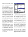
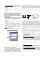
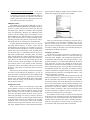
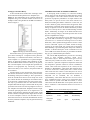
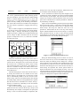
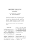
Published in Proc. Intl. Conf. On Bond Graph Modeling 2001
SCS v.33, n.1, 152-157.
ENPORT Model Builder: An Improved Tool for
Multiport Modeling of Mechatronic Systems
Michael K. Hales
Ronald C. Rosenberg
[email protected]
Delphi Automotive Systems
3900 Holland Road
Saginaw, MI 48601
[email protected]
Michigan State University
2555 Engineering Building
East Lansing, MI 48824
Keywords: Model Tools, Model Types, Software Tools
Abstract
Mathematical modeling based on multiport concepts is
a powerful approach for simulation, analysis and design of
mechatronic systems. Multiport concepts can be more
fully exploited when they are embedded in a software environment. An effective modeling environment should not
only support core ideas of multiport modeling, but should
also be easy to use, flexible in design, customizable, and
provide practical support for component libraries. The
environment should be implemented so that the engineer
does modeling of mechatronic systems in a manner congruent with his or her thinking.
In this paper we present the results of an effort to design and implement a multiport modeling environment for
mechatronic systems. many of the features described
above have been realized. Additionally, several novel features have been incorporated into the environment, in cluding support of customizable, user-defined model
types, methods for organizing and browsing the contents
of a model type library, and tools for controlling access of
classes of users to model information. The result is a fully
functional modeling environment called ENPORT Model
Builder. An overview of the design and implementation of
this software is presented.
INTRODUCTION
Analytical tools are becoming increasingly important
in industry. Mathematically-based tools are key to providing significant enhancements to product designs with
decreased development lead time. Mathematical modeling
of mechatronic systems is at the forefront of this trend.
Companies are looking for methods that make investigation of the dynamic behavior of complex systems with
components from multiple power domains as simple as
possible.
Multiport modeling is an excellent method for modeling
the dynamic response of complex, mechatronic systems.
One benefit of multiport modeling is the ability to develop
a model at distinct abstraction levels. This concept was
discussed by Top and Akkermans [1], further developed
by Rosenberg et. al [2], and applied to the structure of a
model library by Breunese et. al [3]. These concepts guide the
model building process in a natural manner by letting an engineer focus on relevant information at the appropriate time. For
example, when modeling a hydraulic line, the precise mathematical relationship that defines the pressure drop across a
bend in the line need not be considered when making decisions about how to organize structure of a system that includes a pump and load.
The power of these modeling concepts is enhanced when
embedded in software. There are various classes of modeling
software widely available and used today. The MATLAB/
Simulink environment [4] is a typical example of a simulation
tool that is widely used in industry today. However, while providing may useful features, this tool has limited support for the
modeling concepts referred to above. Otter and Cellier [5] discuss several limitation of block-diagram type of environments
in general for physical systems modeling, including the requirement of representing equations in a fixed causal form and
the lack of close correlation between a physical system and its
model.
Many other software tools have been developed that are
more appropriate for modeling of mechatronic systems by directly supporting modeling paradigms that include combinations of power and signal connections. A representative list
includes 20-Sim [6,7], Dymola [8], and MS1 [9]. These software
packages provide many excellent tools. In this paper, we present the results of research, design and implementation efforts
to produce a modeling environment that supports mechatronic
design. The modeling environment is called ENPORT Model
Builder, or MB. Several novel and unique features have been
realized, including Templates for User-Defined Model Types,
library organization and browsing tools, and controlled access
to selected model properties. In Section 2 the general properties of the environment are discussed. Section 3 presents the
design and implementation of User-Defined Model Types. The
functionality of a library of model types is discussed in Section
4. The concepts of controlled access and their implementation
are given in Section 5. Conclusions and statements of future
work are given in Section 6.
GENERAL FEATURES
In order to make the MB environment easy to use and accessible to a general user, the design is based on a common
Windows architecture. The environment supports standard features such as an event-driven Graphical User’s
Interface, top-level drop-down menus, toolbars, and scrollable, resizable windows. Whenever possible, elements of
the design, such as the menu structure, were chosen to
mirror typical windows applications.
In addition to supporting common features of Windows-based applications, MB also supports common mu ltiport modeling tools. The fundamental model building
block is a General Multiport as discussed by Rosenberg
et. al [2]. Some characteristics of a General Multiport are
that it can represent a physical system, subsystem, process, or effect; it interacts with its environment through
various types of interface structures called Ports; it supports hierarchical model structuring by defining Subsystem
Components that can contain other Components; and it
has display properties, such as an icon, that can be used
in a graphical modeling environment. The standard bond
graph elements form a subset of the modeling components
that can be represented by a General Multiport; block diagram components form another useful subset.
Figure 1 shows a representation of the MB environment and
demonstrates several of the features discussed above. In
this figure a set of pre-defined General Multiport mo deling
Components appears on the left-hand side of the screen.
Models are built by selecting Components from this list
and placing them in a model window. The figure also
shows the top-level representation of a model in the top
right window labeled “Model1”. This window contains a
model of a common closed-loop feedback system. The
model is hierarchical, meaning that more detailed modeling
information is found by ‘looking inside’ the contents of a
Subsystem Component. As an example, the contents of
the Subsystem Component labeled “Plant” are shown in
the window labeled “Model1:Plant” on the lower righthand side of the screen.
At some point in the model building process, specific
mathematical relationships and parameter values need to
be defined. MB provides an equation editor for specifying
constitutive equations and parameter values. The editor
accepts equations in acausal form, providing for flexible
component definitions. MB defines a set of common, predefined functions (such as sin, integrate, etc.) and provides syntax checking. After a closed-system model is
defined, and an automatic assignment of causality is made
and checked, the system equations are generated. Symbolic equation manipulation is applied where needed. The
current implementation of the MB environment formats
system equations for solution in MATLAB. A companion
application for solving the MB system equations is currently under development.
Figure 1. The MB Environment.
USER-DEFINED MODEL TYPES
A powerful concept for storing engineering knowledge and
reducing the model building effort involves reusing past mo deling efforts in current modeling tasks. One implementation of
this idea is the use of User-Defined Model Types (UDMTs). A
UDMT is a generalized model definition that can be specialized
for a particular purpose. The type definition allows future
modelers to take advantage of previous modeling efforts by
automatically providing certain model details and reducing the
required input to define a usable model. A good model type
provides sufficient details to capture the attributes of a class of
related mo dels, but is flexible enough so that multiple realizations that are substantially different from each other are possible.
An analogous concept is a Pre-Defined Model Type
(PDMT), supported by most modeling environments available
today. A block diagram “Integral” block is common example of
a PDMT. The model type definition specifies that the model
can only be connected to signals and the output variable is the
integral of the input variable. When a new model is being built
and an integrator is needed, the user simply selects the integrator block from the list of available components. PDMTs are
limited because the number of available types is fixed when the
software development is completed. UDMTs provide greater
user flexibility. The modeling environment can be specialized
by defining a set of UDMTs that are the most useful to a particular individual.
The concept of UDMT is not new and has been implemented in other software. Examples are MATLAB’s Sfunctions, Matrixx’s User-blocks [10], and 20-Sim’s model
types. In the MB environment UDMTs are implemented and
supported using Multiport Templates. A Multiport Template
(hereafter referred to as a Template) is an organization of three
sets of data:
1) General Multiport Definition - All information needed
to support a definition of any instance of a General
Multiport,
2) Constraints - A set of Constraints specify the manner
in which an Component instance may be modified, and
3) Defaults - Default values define an initial configuration
of a Component instance.
A simple example will help to illustrate the use of the
above information. Consider a Bond Graph, 1-Port C Component defined as a UDMT in the MB environment, illustrated in Figure 2. To support the commonly expected behavior of this component, the following information is
needed in the Template:
1) General Multiport - The General Multiport Definition
contains power ports, port variables, causality preference, mathematical equations, the equate, integration,
multiply and divide operations, and an icon definition.
2) Constraints - When an instance is created, template
constraints specify that a user cannot add or delete
ports, the state equation cannot be modified, and the
constitutive equation must specify a relationship between the port variable e and the energy variable q.
Constraints are not enumerated at this level of interface. The manner in which component constraints are
accessed is discussed below.
3) Defaults - The default equation is a linear constitutive
equation.
Figure 2. A Bond-Graph, 1-Port C Component.
The Template data defined above allow for different
variations of the C Component to be created, while preserving the fundamental properties of its definition. For
example, the constraints ensure that the constitutive equation cannot be modified to represent a dissipation effects
that are associated with an R Component.
The use of constraints is a unique extension of the
power of UDMT in the multiport modeling methodology.
The Template data structure can be further exploited when
deriving and organizing a set of new Templates. In the MB
environment, when creating a new Template, the user must
always start with an existing Template. A new template inherits
constraints from the parent template. The user defines additional constraints to define a more specialized Template. This
method produces a natural ordering among a set of Templates,
as shown in Figure 3 (a). The possible configurations possible
from a given Template are always a strict subset of the possible configurations of its parent Template, as shown in Figure 3
(b).
Add
Constraints
General
Multiport
Template
T1
T2
Template
3
General
Multiport
Template
Template 1
Template 2
T3
(a) Derivation Tree
(b) Possible Instance Configurations
Figure 3. Derivation of Templates
Consider again the Template for the Bond Graph 1-Port C
Component. This Template could be used to define a more
restrictive Component, a Bond Graph, Linear 1-Port C Component. For the most flexible definition of a new Template, a Ge neral Multiport Template is always available. The General Multiport Template is a special Template that has no constraints or
defaults defined. For a more comprehensive treatment of the
concept of Multiport Templates see Hales [11] and Hales and
Rosenberg [12].
In the MB environment a “Template Wizard” supports the
Template definition process. This tool simplifies Template creation by taking a user through a series of dialogs. A summary of
the Template definition process is given below:
1) Select Parent Template - This step allows the user to select
a Parent from a list of existing Templates. The General
Multiport Template is always available as a parent Template.
2) Specify Template General Properties - General Template
properties included defining whether the component supports model hierarchy or contains equations directly, how
the icon representing component instances is displayed, a
default label, and keywords associated with the Template.
3) Specify Power Port Properties - Constraints on the number, direction, power type, and causal properties of Power
Ports are specified along with default values for each
category.
4) Specify Signal Port Properties - Constraints on the number
and direction of Signal Ports are specified. Default values
for these categories are specified.
5) Specify Template Parameter Properties - A set of default
parameters can be associated with a Template. Constraints
can be given to limit the range of parameter values and to
indicate whether or not the parameter can be deleted from
a Component instance.
6)
Specify Template Equation Properties - A set of default equations can be associated with a Template.
Constraints can be given to limit equation editing to
the right-hand side, limit an equation to be linear, algebraic and/or time invariant, and limit the list of variables that may be used in an equation.
LIBRARY TOOLS
The UDMT tools supported by MB help to create a
flexible and customizable modeling environment. By allowing users to create and save sets of their own, personalized model types, MB can be tailored to meet individual
styles and preferences. However, this additional power
creates a need for dealing with a large number of UserDefined Model Types. When building a new model, finding a useful model type for a current modeling need by
searching through a large, flat list, with only the comp onent name and icon as a reference, can be burdensome.
A typical method for handling this issue is to classify
and group similar models in a “library”. Often, this approach amounts to grouping a set of models in one location. While useful to some degree, using this organization
scheme has several disadvantages. First, generally there
are only three pieces of information that can be used to
help locate a useful model: the library name, the model
name, and the model icon. Second, although a large list of
models is divided up into smaller groups, the contents of a
single library can still become large. Third, there is only
one way to locate a model: by finding it in its library. Multiple location paths are not possible. Fourth, the library
organization reflects the thinking of the person who built
the library, which may not be the same as that of users of
the library.
Many of these issues of library structure and organization and use were addressed by Breunese et. al. [3]. To
assist the modeler in dealing with this issue, MB provides
three additional methods for organizing and searching
through a list of User-Defined Model Types. These methods are based on sorting - by keywords, by constraints,
and by generation history.
Sorting by Keywords
When a user creates a new model type using a Multiport Template, a set of Keywords may be associated with
the Template. Under standard conditions, the list of Templates available to the user includes all Templates that
have been previously defined. However, this list can be
reduced by specifying a set of Keyword Filters. The list of
available keyword filters is automatically generated, based
on the keywords that have been defined in all available
Templates. After a user selects a subset of the available
keyword filters and requests an update of the current list,
only those Templates that have been defined with match-
ing keywords are displayed. Figure 4 shows a MB list of components after applying the “Signal” keyword filter.
Figure 4. Sorting by Keywords.
There are several benefits to filtering by keyword. First, a
set of Templates can be classified in multiple ways, not just
placed in a single group. Second, it is possible to find a Template in a Library in multiple ways. Third, keyword associations
are made according to the desires of an individual, further personalizing the modeling environment.
Sorting by Constraints
One limitation to using keywords as a searching device is
that there is no automatic control over which keywords get
associated with a Template. This situation has the potential to
be misleading and frustrating, with searches leading to inappropriate Templates. To overcome these difficulties, the idea of
using keywords as a filter was extended to using the Constraints that are associated with the Template. For Constraints
that are sufficiently general, it is be possible to search a library
for Templates that have that Constraint. For example, a library
could be searched for Templates that have the Constraint that
“No Power Ports are Allowed”, or for Templates with an “Only
Algebraic Equations” constraint.
This scheme has many of the same benefits discussed with
the keyword method. An additional advantage to this idea is
that the Constraints associated with a Template directly influence its functionality. This result means that it isn't possible to
have a search that produces a poorly matched Template. That
is, the Templates found as a result of a Constraint search are
guaranteed to exhibit the behavior specified by the Constraints. Another advantage is that classifying models based
on what Constraints are applied to them is a natural way to
organize one's thinking about a set of models.
One weakness of this scheme is that the list of Constraints
on which to search is limited to the types of Constraints known
to the system. Also, the Constraints are strictly limited to functionality; abstract classifications that are possible using Keywords are not possible. For these reasons, it is useful to support searching both by keywords and by Constraints.
Sorting by Generation History
A third classification scheme takes advantage of the
Parent-Child relationship between two Templates (see
Figure 3). This relationship sets up a natural ordering of
Templates using a tree structure instead of a flat list. An
example of this sorting method in the MB environment is
shown in Figure 5.
Figure 5. Sorting by Generation History.
One benefit of this type of organization is the guidance
given when searching for a component with a particular
functionality. To understand this benefit, note that a derived Template is a specialization of a parent Template.
Sorting by Generation History takes advantage of this
fact. If a candidate model located in a library is too general,
then a child Template can be sought that specializes the
behavior in an appropriate way. Conversely, if a model
found in the library is too restrictive, the parent model can
be considered.
Another benefit to this classification arises from the
fact that the classification structure can be patterned after
the thinking of the person building it. This is possible because the classification structure is not unique. For exa mple, consider the task of initializing an environment with a
set of electrical components that only have Power Ports.
One way to go about this task is to first define a Parent
Template that adds the single constraint that all the power
ports must be electrical. The next step might be to derive a
new Template from this Parent Template and add a single
Constraint specifying that there are no Signal Ports. An
equally valid option for obtaining the same results would
be first to define a Template with no Signal Ports and then
to use this Template to derive one that adds the Constraint that all Ports are electrical. Both methods result in
the nearly identical Templates; only the generation history
is different.
CONTROLLED ACCESS TO MODEL ATTRIBUTES
A developing trend in industry is to outsource modeling
efforts, and to increase the sharing of models between customers and suppliers. One of the concerns with this trend is the
protection of proprietary information. A simple solution commonly used is to prevent access to the entire contents of a
model, thus making the model a "black box." In this case, use
of such a model is greatly restricted. Such an approach, while
protecting the investment of the model provider, can be frustrating to engineers who use the model. Models may be difficult to use correctly due to a lack of understanding of model
details. Additionally, if changes to the model become necessary due to design changes, the model provider must be employed to implement the change.
The concerns described above were addressed in the design of the MB environment by supporting a concept termed
Controlled Access. Instead of restricting access to an entire
model file, a more sophisticated approach was used to control
access to individual aspects of a model. Instead of simply
"locking up" an entire model, only critical parts are protected.
More flexibility is provided and greater utility from a model is
possible. A detailed description of the controlled access features of MB can be found in Hales [11] and Hales and Rosenberg [13]. A condensed description follows.
The current MB implementation provides for controlling
access to three modeling structures, called AccessControllable Objects. These objects and the types of access
values they may assume are shown in Table 1. A “None” access value for a particular component’s Equations means that
the component’s equations cannot be viewed or modified; a
“Read” value means that equations can be viewed, but not
modified; a “Read/Modify” value means that Equations have
no access restrictions. A Subsystem with a “None” access
value means that the contents of the subsystem can not be
view or modified; A “Open” value means that the contents of a
subsystem can be examined, but not mo dified; a
“Open/Modify” value means that there are no access restrictions. A Model File with a “None” access value means that a
model cannot be opened in the MB environment; a “Load”
value means that the Model File can be opened, but not modified; a “Load/Save” value means that there are not access restrictions.
Table 1. Access-Controllable Objects and Values.
Object
Access Values
Equations
None
Read
Read/Modify
Subsystem
Contents
None
Open
Open/Modify
Model File
None
Load
Load/Save
To implement these ideas, the concepts of “Groups”
and “Users”, patterned after the UNIX operating system
[14], was introduced. At all times during a model building
session, a variable defining the Current User exists. The
Current User is a system parameter used to identify the
person currently working in the modeling environment.
The value of the Current User Variable can be changed at
any time, which is equivalent to "logging off" and "logging on".
Next, as shown in Figure 6, each Model File contains a
set of Groups. Four groups appear in the current design:
Owner, Group 1, Group 2, and World. In principle the
number of groups is variable, but is considered fixed in the
current design of MB. Associated with the first three
groups is a unique list of Users; i.e., each User is a member
of exactly one group.
Group 2 Users can only read its equations, and that Word Users can neither read nor modify its equations.
A User classified as an Owner always has complete access
to all data in a model. In addition, an Owner can add and delete
Users from any of the Groups. The sole restriction is that the
Current User cannot be removed from the Owner List. If this
option were available, then it would be possible for a Model to
be permanently "locked up".
Figure 7 shows the MB dialog used for specifying the members of the Owner, Group 1, and Group 2 Groups. This dialog
can only be accessed if the Current User is a member of the
Owner Group. The Group for which the Users are to be
specified is selected from the list on the top of the dialog.
Figure 7 indicates that the list of Users for Group 1 is currently
being specified. The list of Users of the currently selected
group appears in the bottom half of the display. Figure 7 also
indicates that three Users currently belong to Group 1.
Model File
Group 1
Group 1
User 1
...
...
Owner
User 1
Group 2
Owner
User n
World
Group
Group 2
User 1
...
Owner
Group
Group 1
User n
Group 2
User n
Figure 6. Organization of Groups and Users.
Using this classification scheme, the Current User is
always identified as belonging to exactly one Group. If the
Current User is among the Users on the Owner list, then
the Current User is considered an Owner. If the Current
User is among the Users on the Group 1 list, then the Current User is consider a Group 1 User. If the Current User is
not contained on any list, then the Current User is considered a World User.
The functional purpose of the data structure above is
to classify the Current User as a member of one of the
Groups. When a new Model File is created, the Current
User is automatically added to the list of Users of the
Owner Group. The lists associated with the other Groups
are initially empty. When an existing Model File is opened,
then the Current User is identified as an Owner, Group 1,
Group 2, or World User, depending on the user information stored with the model.
Each access-controllable object maintains an independent set of access values for the Group 1, Group 2, and
World Groups. For example, a Component can specify that
Group 1 Users can read and modify its Equations, that
Figure 7. Interface for Editing Group Members.
During the model building process an Owner User can set
the access values for any access-controllable object. Figure 8
shows the dialog for defining access settings for a Comp onent's Equations. On the left-hand side of the dialog the Group
for which Access Values are to be set is selected. On the righthand side of the dialog the access values for the currently selected Group are specified. The current options shown in
Figure 8 indicate that any user belonging to Group 1 can only
view the Equations associated with the currently selected Core
Component. Similar dialogs are available for specifying access
settings for a Subsystem Component and a Model File.
Figure 8. Restricted Access to Equations.
CONCLUSIONS AND FUTURE WORK
In this paper we have presented the results of the design and implementation of a Multiport Modeling environment for mechatronic systems. The environment is
called ENPORT Model Builder, or MB. The modeling environment is an attempt to allow for models to be constructed in ways that are congruent with the ways in
which engineers like to work. Additionally several novel
features are supported, including Multiport Templates,
filter-based library organization and browsing tools, and
controlled access to Multiport Model properties.
The result of this work is a functional environment that
enhances the model building effort. System equations are
formatted for solution in the MATLAB environment. An
earlier version of MB was successfully used in an undergraduate mechatronics modeling course for mechanical
engineering students at Michigan State University.
Future development of the MB environment includes
plans to make the software more robust, provide additional
Graphical User Interface features, enhance the Template
capabilities, and handle a larger class of modeling problems. A concurrent effort is being made to complete a
complementary environment for numerically solving the
system equations and displaying the solutions.
REFERENCES
[1] Top, J. Akkermans, H., 1993, "Layered Modeling of
Physical Systems", DCS-Vol. 47, Automated Modeling for Design, pp.95-107.
[2] Rosenberg, R., Hales, M., and Minor, M., 1996, “Engineering Icons for Multidisciplinary Systems”, Proceedings ASME Dynamic Systems and Control Division, DSC-Vol.58, 665-672.
[3] Breunese, A.P.J., J.L. Top, J.F. Broenink, and J.M. Akkermans, 1998, ”Libraries of Reusable Models: Theory
and Application", Simulation, 71:7, pp 7-22.
[4] MathWorks, 1999, MATLAB 5.3 / Simulink 3.0, Natick,
Massachusetts.
[5] Otter, M. and F. Cellier, 1996, "Software for Modeling
and Simulating Control Systems", The Control Handbook , CRC Press, Boca Raton, FL, pp. 415-428.
[6] Broenink, J.F., 1999, "20-SIM Software for Hierarchical
Bond-Graph/Block-Diagram Models", Simulation
Practice and Theory, No. 7, pp. 481-492.
[7] Controllab Products, 1999, 20-Sim Reference Manual,
Version 3.0, Enschede, Netherlands.
[8] Dynasim AB, 1999, Dymola - Dynamic Modeling Laboratory, [Online] Available http://www.dynasim.com/,
November 16, 1999.
[9] Lorenz, F. 1997, Modeling System 1, User Manual,
Lorenz Simulation, Liege, Belgium.
[10] Integrated Systems, Inc. 1994, SystemBuild User's Guide
Version 4.0, Santa Clara, CA.
[11] Hales, M.K., 1999, Computer Aided Engineering Tools for
Structured Modeling of Mechatronic Systems, Ph.D. Dissertation, Michigan State University.
[12] Hales, M. K. and R. Rosenberg, 2000, “Structured Modeling of Mechatronic Components Using Multiport Templates”, to appear, Proceedings, ASME IMECE 2000,
Automated Modeling.
[13] Hales, M. K. and R. Rosenberg, 2000, “A Plan For Controlled Access to Multiport Model Properties”, Proceedings, First IFAC Conference on Mechatronic Systems,
Darmstatdt, Germany, September 2000, 699-704.
[14] Stallings, W. (1998). Operating Systems: Internals and
Design Principles, Prentice Hall, Upper Saddle River, NJ.