1
When using this document, keep the following in mind:
nti
al
General Notice
1. This document is confidential. By accepting this document you acknowledge that you are bound
by the terms set forth in the non-disclosure and confidentiality agreement signed separately and /in
the possession of SEGA. If you have not signed such a non-disclosure agreement, please contact
SEGA immediately and return this document to SEGA.
de
2. This document may include technical inaccuracies or typographical errors. Changes are periodically made to the information herein; these changes will be incorporated in new versions of the
document. SEGA may make improvements and/or changes in the product(s) and/or the
program(s) described in this document at any time.
nfi
3. No one is permitted to reproduce or duplicate, in any form, the whole or part of this document
without SEGA’S written permission. Request for copies of this document and for technical
information about SEGA products must be made to your authorized SEGA Technical Services
representative.
4. No license is granted by implication or otherwise under any patents, copyrights, trademarks, or
other intellectual property rights of SEGA Enterprises, Ltd., SEGA of America, Inc., or any third
party.
Co
5. Software, circuitry, and other examples described herein are meant merely to indicate the characteristics and performance of SEGA’s products. SEGA assumes no responsibility for any intellectual
property claims or other problems that may result from applications based on the examples
describe herein.
GA
6. It is possible that this document may contain reference to, or information about, SEGA products
(development hardware/software) or services that are not provided in countries other than Japan.
Such references/information must not be construed to mean that SEGA intends to provide such
SEGA products or services in countries other than Japan. Any reference of a SEGA licensed product/program in this document is not intended to state or simply that you can use only SEGA’s
licensed products/programs. Any functionally equivalent hardware/software can be used instead.
7. SEGA will not be held responsible for any damage to the user that may result from accidents or any
other reasons during operation of the user’s equipment, or programs according to this document.
SE
NOTE: A reader's comment/correction form is provided with this
document. Please address comments to :
SEGA of America, Inc., Developer Technical Support (att. Evelyn Merritt)
150 Shoreline Drive, Redwood City, CA 94065
SEGA may use or distribute whatever information you supply in any way
it believes appropriate without incurring any obligation to you.
(11/2/94- 002)
SE
GA
Co
nfi
de
nti
al
TM
SCU DSP
Assembler
User's Manual
Doc. # ST-240-A-042795
© 1995 SEGA. All Rights Reserved.
nti
al
READER CORRECTION/COMMENT SHEET
Keep us updated!
If you should come across any incorrect or outdated information while reading through the attached
document, or come up with any questions or comments, please let us know so that we can make the
required changes in subsequent revisions. Simply fill out all information below and return this form to
the Developer Technical Support Manager at the address below. Please make more copies of this form if
more space is needed. Thank you.
General Information:
Phone
de
Your Name
Document number
ST-240-A-042795
Document name
SCU DSP Assembler User's Manual
Date
Corrections:
Correction
nfi
pg. #
GA
Co
Chpt.
SE
Questions/comments:
Fax:
Where to send your corrections:
(415) 802-1717
Attn: Evelyn Merritt,
Developer Technical Support
Mail:
SEGA OF AMERICA
Attn: Evelyn Merritt,
Developer Technical Support
150 Shoreline Dr.
Redwood City, CA 94065
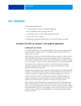
1. Overview
nti
al
The SCU DSP assembler is designed to develop DSP instruction code and to simulate
their execution under MS-DOS and UNIX environments. Linking of code is not required since the assembler outputs code in Motorola S format. The DSP assembler
requires a substantial knowledge of the hardware; therefore, the user is advised to
have a thorough understanding of the DSP hardware prior to use.
2. Running the Assembler
de
dspasm [option] <source filename>
1) The following options are available (files can be created only after the program
terminates execution without errors.)
Output list
Output data in SH assembler format
Output data in C format
To use the MODEL M development target
nfi
-l[Filename]:
-a[Filename]:
-c[Filename]:
-m:
Co
2) There are no default file extensions set for source filenames.
3) Only the errors detected in the initial search are displayed. Correct the errors and
assemble the code repeatedly until all errors are eliminated.
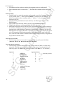
3. How to Write a Program
[label] [∆operation [∆operand]] ... [comment(s)]
Ex:
LABEL:
MOV MC0, X
;
comment(s)
SE
GA
1) Labels
• Defined by the programmer, and used as the destination address for the JMP
instruction.
• When writing labels, begin from the first column, or use a colon “:” at the end
of the word (ex. LABEL: ).
• Labels can be as long as 32 characters in length, and upper or lower case English
letters, numbers, and underscores(_) may be used. Numbers may not be used as
the first character. Also, the labels are not case- sensitive.
2) Operations
• Write the DSP execution instructions.
• When writing code that begins with an operation, enter a blank space before the
operation.
• As many as six operand instructions can be listed under one operation (applicable to operand instructions only).
3) Operands
• List operands required for the execution of operations.
• Insert a space between operands.
SCU DSP Assembler User's Manual
1
nti
al
4) Comments
• Comments can be written to make the program easier to understand.
• Start comments with a semi-colon “;” and end the comment at the end of the
line.
*Note on writing:
•
•
•
de
•
The basic rule is to write the operation and operand on one line; however, when this
is not possible, enter “\” before pressing Return to continue on to the next line. To
follow an operation after a comment, enter “\” before “;”. Also, do not exceed 255
characters per line.
Operations and operands are not case sensitive; use either upper or lower case
English letters.
Specify $xx for hexadecimal, xxx for decimal, and %xxxxxxxx for binary.
Output code addresses can be specified by the ORG directive.
Although the program area in DSP only has a maximum capacity of 256 instructions,
it can issue a “warning” and output code containing up to 2048 instructions to facilitate tasks such as the splitting of processes or optimization. However, only the SCU
DSP Simulator can support this code. Therefore, it is necessary to edit the code down
to its 256 instruction limit during assembly, if the code is actually used in the DSP.
Also, note that if the number of address labels exceeds 256 instructions, assignment is
not possible with 8-bit values.
nfi
•
* Note on reserved words:
•
The following names are reserved for operands and may not be used for labels.
* Note on numeric operations:
•
Co
{ALH ALL ALU M0 M1 M2 M3 MC0 MC1 MC2 MC3 MUL}
The following operators can be used when setting values on labels, or when using
numerical values for operands (When the following are used as operands, do not
enter any spaces. Ex. JMP $+2 is correctly written, while JMP $ + 2 is incorrect.)
Operators
Operator Priority
addition
subtraction
multiplication
division
remainder
bit negation
bit product
bit sum
exclusive bit sum
left shift
right shift
SE
GA
+
–
*
/
%
~
&
|
^
<<
>>
2
1.
2.
3.
4.
5.
6.
+ – ~ (monadic operator)
* / %
+ –
<< >>
&
| ^
4. Summary of Instructions
nti
al
1) Operation instructions:
NOP AND OR XOR ADD SUB AD2 SR RR SL RL RL8 CLR MOV
2) “Load immediate” instruction:
MVI
3) DMA instructions:
DMA DMAH
JMP
5) LOOP BOTTOM instructions:
BTM LPS
6) END instructions:
nfi
END ENDI
Directive summary:
Defines labels.
Specifies starting address where instructions are located.
Enter at the end of the program, anything beyond this point is
ignored.
Co
EQU(=)
ORG
ENDS
de
4) JUMP instruction:
IF <numerical value, label>
When the resulting calculated numerical or label value is any
value other than 0, the program assembles from that point on to
ELSE or ENDIF.
IFDEF <label>
SE
GA
When labels are defined first, the program assembles from that
point to ELSE or ENDIF (Up to 16 levels of IF and IFDEF
nestings are supported).
SCU DSP Assembler User's Manual
3
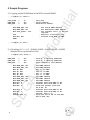
5. Sample Programs
;
———sample (1) start———
COPY_SIZE
RAM0_ADR
RAM1_ADR
=
=
=
12
$00
$00
; Copy size
; Source address
; Destination address
; Set source RAM0 address
; Set destination RAM1 address
; Set transfer size-1 in the LOP
register
; Execute 1 instruction loop
; Transfer from RAM0 to RAM1
de
MOV RAM0_ADR, CT0
MOV RAM1_ADR, CT1
MOV COPY_SIZE-1, LOP
LPS
MOV MCO, MC1
ENDI
———sample (1) end———
nfi
;
nti
al
1) Copying internal RAM0 data of the DSP to internal RAM1.
2) Calculating 2 x 3 + 4 x 5. (RAM0 x RAM1 + RAM0 x RAM1 = RAM2)
(Sample 2b is an optimization of 2a)
———sample (2a) start———
=
=
=
$00
$00
$00
MOV
MOV
MVI
MVI
MVI
MVI
MOV
MOV
MOV
MOV
MOV
MOV
RAM0_ADR,
RAM1_ADR,
#2, MC0
#3, MC1
#4, MC0
#5, MC1
RAM0_ADR,
RAM1_ADR,
RAM2_ADR,
MC0, X
MC1, Y
MUL, P
CT0
CT1
MOV
MOV
CLR
AD2
MC0, X
MC1, Y
A
MOV ALU, A
CT0
CT1
CT2
SE
4
; Store 2, 4 starting addresses
; Store 3, 5 starting addresses
; Store results at this address
Co
RAM0_ADR
RAM1_ADR
RAM2_ADR
;
;
;
;
;
;
;
;
;
;
;
;
Set RAM0 address
Set RAM1 address
Set “2” in RAM0
Set “3” in RAM1
Set “4” in RAM0
Set “5” in RAM1
Set RAM0 address
Set RAM1 address
Set RAM2 address
Transfer data from RAM0
Transfer data from RAM1
Store the product of RX
RY at PH, PL
Transfer data from RAM0
Transfer data from RAM1
Set ACH, ACL to “0”
Store the sum of PH, PL
ACL at ACH, ACL
GA
;
;
;
;
;
to RX
to RY
and
to RX
to RY
and ACH,
AD2 MOV ALL, MC2
; Store the product between RX
and RY at PH, PL
; Store the sum of PH, PL and ACH,
ACL in RAM2
nti
al
MOV MUL, P
ENDI
;
;
———sample (2a) end———
———sample (2b) start———
RAM0_ADR
RAM1_ADR
RAM2_ADR
=
=
=
$00
$00
$00
; Store 2, 4 starting addresses
; Store 3, 5 starting addresses
; Store results at this address
#2,
#3,
#4,
#5,
MC0
MC1
MC0
MC1
MOV MC0,X
MOV MC0,X
AD2
AD2
ENDI
———sample (2b) end———
MOV MC1,Y
MOV MC1,Y
MOV RAM0_ADR, CT0
MOV RAM1_ADR, CT1
MOV RAM2_ADR, CT2
CLR A
MOV ALU,A
MOV ALL, MC2
Co
;
MOV MUL,P
MOV MUL,P
nfi
MVI
MVI
MVI
MVI
de
MOV RAM0_ADR, CT0
MOV RAM1_ADR, CT1
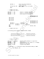
3) Calculating matrix multiplies. (RAM0 X RAM1 = RAM2)
;
GA
/ M 00 M 01 M 02 M 03\ / 1 0 0 x\
/M 00 M 01 M 02 M 03\
| M 10 M 11 M 12 M 13 || 0 1 0 y | → | M 10 M 11 M 12 M 13 |
\M 20 M 21 M 22 M 23/ | 0 0 1 z |
\M 20 M 21 M 22 M 23/
\0 0 0 1 /
———sample (3) start———
=
=
=
=
=
SE
DATA_TOP
MAT_SIZE
RAM0_ADR
RAM1_ADR
RAM2_ADR
;
;
$10000>>2
$0C
$00
$00
$00
;
;
;
;
;
External memory address is 4 byte units
Array size
Starting address that stores X, Y, Z changes
Address for array work
Original array address
(Transfers x, y, z translation arrays from external memory to RAM0)
MVI DATA_TOP, RA0
SCU DSP Assembler User's Manual
5
MOV RAM0_ADR, CT0
;
;
D0, MC0, #$02
nti
al
DMA
(Copy matrix operands from RAM2 to RAM1)
MOV RAM2_ADR, CT2
MOV RAM1_ADR, CT1
MOV MAT_SIZE-1, LOP
LPS
MOV MC2, MC1
WAITING:
JMP TO, WAITING
(Calculate arrays)
de
;
;
MOV RAM0_ADR, CT0
MOV RAM1_ADR, CT1
MOV MC0, X
MOV MC0, X
MOV MC0, X
MUL,
MUL,
MUL,
MUL,
MUL,
MUL,
MUL,
MUL,
MUL,
MUL,
MUL,
MUL,
P
P
P
P
P
P
P
P
P
P
P
P
MOV
MOV
MOV
MOV
MOV
MOV
MOV
MOV
MOV
MOV
MOV
MOV
MC1,
MC1,
MC1,
MC1,
MC1,
MC1,
MC1,
MC1,
MC1,
MC1,
MC1,
MC1,
Y
Y
Y
Y
Y
Y
Y
Y
Y
Y
Y
Y
CLR
MOV
MOV
MOV
CLR
MOV
MOV
MOV
CLR
MOV
MOV
MOV
A
ALU,
ALU,
ALU,
A
ALU,
ALU,
ALU,
A
ALU,
ALU,
ALU,
A
A
A
MOV
MOV
MOV
MOV
MOV
MOV
MOV
MOV
MOV
MOV
MOV
MOV
A
A
A
A
A
A
SE
GA
; ------- sample (3) end -------
6
RAM0_ADR, CT0
#1, RX
RAM2_ADR+3, CT2
ALL, MC2
RAMO_ADR, CT0
#1, RX
RAM2_ADR+7, CT2
ALL, MC2
RAMO_ADR, CT0
#1, RX
RAM2_ADR+11, CT2
ALL, MC2
nfi
MOV MC0, X
MOV MC0, X
MOV MC0, X
MOV
MOV
MOV
MOV
MOV
MOV
MOV
MOV
MOV
MOV
MOV
MOV
Co
AD2
AD2
AD2
AD2
AD2
AD2
AD2
AD2
AD2
AD2
AD2
AD2
ENDI
MOV MC0, X
MOV MC0, X
MOV MC0, X
END