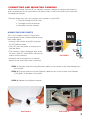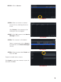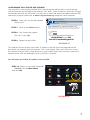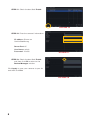
1
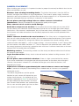
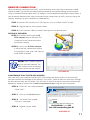
QT SERIES
IP CAMERAS
QUICK START
Thank You for Choosing a Q-See Product!
We are proud to back up our products with conditional service warranty covering all hardware
for 24 months from the date of purchase. But, we are also here to help you get the most
out of your system even if there aren’t any issues. Our self-help Knowledge Base, located
at www.Q-See.com/Support has the answers to the most common questions. If you can’t
find the solution to your problem, please feel free to contact our live support during the hours
shown below.
PRODUCT SUPPORT, DOWNLOADS,
FIRMWARE UPDATES & MANUALS
24/7 Technical Resource Data Base
Live Chat (M-F, 6am - 7pm Sat & Sun 9am - 5pm PST)
www.Q-See.com/Support
ABOUT THIS MANUAL
This Quick Start manual will help you get your IP camera online - whether
you’ll be connecting it to an NVR, or using it in stand-alone (remote) mode.
Detailed instructions on operating your camera using an NVR, computer or
mobile device are contained in the User Manual or Remote Monitoring
Guide on the CD included with your product. You will also find any needed
computer software on this CD as well. Additional information can be
downloaded from our support website at www.Q-See.com/Support.
This manual was accurate at the time it was completed. However, because
of our ongoing effort to constantly improve our products, along with
smartphone and router manufacturers adding and changing features on
their products, it is possible that some functions may change from how
they are described. We encourage you to visit our website at www.Qsee.com to check for the latest firmware and sofware updates as well as
product announcements.
© 2014 Q-See. Reproduction in whole or in part without written permission is prohibited. All
rights reserved. This manual and software and hardware described herein, in whole or in part,
may not be reproduced, translated, or reduced to any machine-readable form without prior
written approval.
Trademarks: All brand names and products are trademarks or registered trademarks of their
respective owners.
Q-See is a registered trademark of DPS, Inc.
Disclaimer: The information in this document is subject to change without notice. The
manufacturer makes no representations or warranties, either express or implied, of any kind
with respect to completeness of its contents.
Manufacturer shall not be liable for any damages whatsoever from misuse of this product.
CONNECTING AND MOUNTING CAMERAS
What makes Internet Protocol (IP) or Network cameras different is that they each have a
little computer processor inside them that allows them to talk to the NVR over a network including the Internet.
There are three ways you can connect your cameras to your NVR:
1. Directly through the PoE Ports
2. Through your local network
3. Remotely over the Internet
USING THE POE PORTS
This is the simplest method. These ports
provide power to the camera while receiving
their video signal.
NVR
• Connect the camera and NVR using the
RJ-45 Ethernet cable.
POE
Block
• The PoE port can power a camera up to
200 feet away.
• The camera’s video will appear after a few
seconds. (Non QT-series NVRs will need to
search for the camera)
PICTURE 1
• Cameras will be assigned to a channel
based on the order they were connected.
STEP 1. Connect one of the long Ethernet cables to the socket on the wire leading from
the camera.
STEP 2. Plug the other end of the Ethernet cable into any of the Power over Ethernet
(PoE) ports on the back of the NVR.
STEP 3. Repeat for additional cameras.
1
VGA
2
PICTURE 2
PICTURE 3
3
ON YOUR LOCAL NETWORK
Instead of running the cable directly between
your camera and NVR, you can connect the
camera to the same network used by your
NVR.
POE
Block
• The camera will require its own power
NVR
NVR
NVR
Network Router
Port
POE
Block
POE
supply, called a “POE Injector” or a power
supply at the camera’s location
• Both the camera and NVR must be on the
same network (ie; connected to the same
router)
PICTURE 4
• The camera’s video will be received by
the NVR through the latter’s network
connection.
• To view video from networked cameras, you will need to have the NVR search for the camera
on the network.
The steps below are for use with Q-See’s QT-Series NVRs. To connect using another brand or
series, please consult that NVR’s manual.
STEP 1. Connect the camera to a POE
Injector, such as Q-See’s QAPE
model (right).
STEP 2. Plug the injector into a power
outlet.
PICTURE 5
STEP 3. Use a network cable to connect
the injector to a network port.
STEP 4. Select IP Camera from the
Main Menu.
IP Camera
PICTURE 6
4
STEP 5. Click on Search.
PICTURE 7
STEP 6. Select a camera or cameras
from the list by checking the box to
its left.
Click Refresh, if the camera you’re
looking for does not appear.
STEP 7. Click OK to return to the Device
Manager window.
PICTURE 8
STEP 8. The camera is still disabled.
Select a camera and click on Setup in
the lower left of the Device Manager
window.
PICTURE 9
STEP 9. Check the box titled Enable and
then click OK.
Repeat to enable other cameras.
Click Apply to save your cameras to your list
and then click Exit.
PICTURE 10
5
OVER THE INTERNET
This allows you to connect to cameras in a
completely different location.
• You will need to use the IP Tool (PC) or
the NVMS software (Mac) included on
the Manuals and Software CD or by
download from www.Q-See.com/support.
Router
NVR• Follow instructions
NVRin theNetwork
Port
IP Camera
Manual (also on the CD) to get the IP
POE
POE
POE
address
of the camera.Block
Block
Router/
Modem
POE
Internet
NVR
Network Router/
Port Modem
POE
Block
POE
• Once you have the IP address of the
camera, you can add it to the NVR through
the following steps:
PICTURE 11
The steps below are for use with Q-See’s QT-Series NVRs. To connect using another brand or
series, please consult that NVR’s manual.
STEP 1. Connect the camera to a POE Injector, such as Q-See’s QAPE model.
STEP 2. Plug the injector into a power outlet.
STEP 3. Use a network cable to connect the injector to a network port.
OBTAIN IP ADDRESS:
STEP 4. Install the IP Tool sofware
onto a Windows PC connected to the
same network as the remote camera.
PICTURE 12
STEP 5. Launch the IP Tool sofware. It
will locate the camera and display its
information.
Mac users will need to install CMS or
NVMS.
NOTE! The IP address shown
is only for your local network.
The NVR cannot use this to
connect to the camera over
the Internet.
6
PICTURE 13
CONFIRMING THAT PORTS ARE OPENED
Like your NVR, your cameras feature UPnP technology that allows them to communicate
with the network and through to the Internet. Two “ports” (think of them as doorways through
the firewall) are used; 85 and 6036. You will want to verify that these have been automatically
opened by using an online tool at www.canyouseeme.org using the same computer.
STEP 6. Enter “85” into the box labeled
“What Port?”
STEP 7. Click on the Check button.
STEP 8. You should see a green
“Success” message.
STEP 9. Repeat for port 6036.
Browser - Windows Internet Explorer
http://canyouseeme.org/
Open Port Check Tool
CanYouSeeMe.org - Open Port Check Tool
This page will serve as a free utility for remotely verifying a port is open or closed. It will
be useful for users who wish to check to see if a server or ISP is blocking certain ports.
Your IP: 81.919.622.24
What Port?
Check
Success: I can see your service on
81.919.622.24 on port (85)
Your ISP is not blocking port 85
PICTURE 14
This website will also display your Public IP address near the top of the page above the
box where you entered your port number. This is the number which you will use to access
the camera using the NVR, a web browser or your mobile device from outside of your local
network (away from the building in which your DVR is located).
You will enter this Public IP address into the NVR.
Fine
STEP 10. Return to your NVR. Select IP
Camera from the Main Menu.
Click on Add.
IP Camera
PICTURE 15
7
STEP 11. Check the box titled Enable.
PICTURE 16
STEP 12. Enter the camera’s information:
IP address: Shown on
CanYouSeeMe.org
Server Port: 85
User Name: admin
Password: 123456
PICTURE 17
STEP 13. Check the box titled Enable
and then click OK to return to the
Device Manager window.
Click Apply to save your cameras to your list
and then click Exit.
PICTURE 18
8
CAMERA PLACEMENT
When installing your camera, it is important to select a proper site not only for field of view, but for
other considerations as well:
Distance from viewing/recording device. The further the camera is from the NVR or
monitor, the higher the chances of signal degradation. The camera’s power supply should be
located as near to the camera as possible when the distance exceeds 200’ as the power level will
drop over extended distances resulting in a decrease in video quality.
Do not place near high voltage wires or other sources of electrical
interference. Electrical interference will degrade the quality of the signal.
Place camera out of reach to avoid damage.
Avoid direct exposure to weather. Do not place the camera where rain or snow will hit
the lens directly nor should the camera be placed so that the sun or bright light shines directly
into the lens. Your camera is weatherproof, but it will not work when submerged in water. Ensure
that all power and video connections are not directly exposed to water and are protected from
the elements.
Indoor cameras should not be used outdoors. Even if they are in a sheltered location,
they can still suffer damage due to humidity, dust and other environmental factors. Each camera
has an Ingress Protection (IP) rating which defines how protected the internal workings of the
camera are from solid objects - such as fingers or bugs - dust and moisture. In an IP rating, there
are two numbers that follow the letters “IP.” The first represents the protection from solids while
the second represents the housing’s protection from moisture. A camera should have a minimum
rating of IP65 for trouble-free use outdoors.
Mounting surface. The mounting surface must be sturdy and able to hold at least five times
the camera’s total weight.
Legal Considerations. Always check state and local laws before installing cameras. (2011
NEC 820.44)
Do not place camera behind a window. If there is a light source behind the camera,
it can cause a reflection in the window that will obscure events on the other side of the glass.
Likewise, the camera’s infrared LEDs will reflect off the glass and shine into the lens, thus
degrading the image.
Light levels should be approximately the same between camera and target
area. A camera in a brightly-lit area looking into a shaded area, or vice versa, may produce
inadequate results.
The above are guidelines and the optimal
location for your camera will depend on your
unique circumstances. As a general rule, the
locations highlighted in Green in the picture to
the right indicate the best locations to mount
your camera. Both locations are sheltered from
rain or snow and offer good sight lines to allow
your camera to monitor a wide area.
PICTURE 19
9
Because your camera is weatherproof, it requires less protection than weather-resistant cameras
and it can be placed in more exposed locations if needed. Keep in mind that most Q-See QT IP
cameras are designed to operate between -40°F to 122°F (-40°C to 50°) with a relative humidity
of up to 95%) and consider wind chill and other environmental factors when selecting your
location.
Specialty cameras are also available from Q-See which are able to operate in more extreme
environments.
ADDITIONAL CONSIDERATIONS
Most users prefer to operate their systems with the NVRs recording only when motion is
detected. This provides the most efficient use of the hard drive’s capacity, plus making it easier
for a recording to be located. However, if the a camera’s location has a lot of “environmental”
motion, such as a fan, wind, or the like, you will receive a lot of “false alarms.” Usually, these
events can be avoided by simply adjusting the placement of the camera.
Some easily avoidable situations are presented below:
TV/Computer Screens. If the camera can see a video screen, it will trigger a motion alarm
any time the screen changes, whether there is a video or simply a screen saver. The screen can
be masked in the NVR, or you can also reduce the level of motion sensitivity in specific areas of
the screen.
Fans/Machinery. Motion is motion and if machinery within the camera’s field of view starts
automatically, it will cause an alert. Similarly, if the camera is mounted on a wall with machinery on
the other side that causes it to vibrate, that can also cause it to detect motion. Moving machinery
within the camera’s field of view may be masked off as mentioned above, or motion detection may
be turned off for that channel. If there is another camera that covers access to the area where the
machinery is located, you can set it so that the first camera will only be recording when triggered
by a motion event detected by this second camera.
Bugs. An occasional insect flying through the field of view is usually not enough to trigger an
alert. However, some flying insects are attracted to infrared light and will swarm the camera.
This is usually a temporary situation that occurs at only a certain time of the year. Lighting the
area with yellow “bug light” of sufficient brightness can keep the camera operating in daylight
mode and keep the infrared LEDs turned off. A second solution is to set the channel to record all
the time, and turn motion detection off at night until “bug season” is over. Reducing the motion
sensitivity can also reduce alerts as can using another camera to trigger recording as described
above.
Additionally, keep your cameras clear of spider webs as the movement of the webs due to wind
or critters in the web will cause an alert. The reflection of the infrared off the webs and back into
the camera will also reduce the night vision range.
Snow/Rain. As with bugs, this is usually a seaonal event and may require motion detection to be
temporarily disabled to avoid false alarms. However, positioning the camera further under shelter,
such as closer to the wall and away from the edge of the eaves, can make the rain or snow too
small for the camera to notice. Adjusting motion sensitivity may also help in some situations.
10
REMOTE CONNECTION
When not directly connected to an NVR, it can be directly accessed using a computer, mobile
phone or tablet. The camera will need to be connected to the Internet through a local network
using a standard Ethernet cable and its IP address must be obtained following the steps below. If
you’ve already followed these steps to connect to the camera from an NVR, you may skip to the
sections covering use on a computer or mobile device.
STEP 1. Connect the camera to a POE Injector, such as Q-See’s QAPE model.
STEP 2. Plug the injector into a power outlet.
STEP 3. Use a network cable to connect the injector to a network port.
OBTAIN IP ADDRESS:
STEP 4. Download and install the IP
Tool sofware onto a Windows PC
connected to the same network as
the remote camera.
STEP 5. Launch the IP Tool sofware.
It will locate the camera and display
its information. Mac users will need to
install CMS or NVMS.
PICTURE 20
NOTE! The IP address shown is
only for your local network. The
NVR cannot use this to connect
to the camera over the Internet.
PICTURE 21
CONFIRMING THAT PORTS ARE OPENED
Like your NVR, your cameras feature UPnP technology that allows them to communicate
with the network and through to the Internet. Two “ports” (think of them as doorways through
the firewall) are used; 85 and 6036. You will want to verify that these have been automatically
opened by using an online tool at www.canyouseeme.org using the same computer.
STEP 6. Enter “85” into the box labeled
“What Port?”
Browser - Windows Internet Explorer
http://canyouseeme.org/
Open Port Check Tool
STEP 7. Click on the Check button.
CanYouSeeMe.org - Open Port Check Tool
This page will serve as a free utility for remotely verifying a port is open or closed. It will
be useful for users who wish to check to see if a server or ISP is blocking certain ports.
STEP 8. You should see a green
“Success” message.
STEP 9. Repeat for port 6036.
Your IP: 81.919.622.24
What Port?
Check
Success: I can see your service on
81.919.622.24 on port (85)
Your ISP is not blocking port 85
PICTURE 22
11
This website will also display your Public IP address near the top of the page above the
box where you entered your port number. This is the number which you will use to access
the camera using the NVR, a web browser or your mobile device from outside of your local
network (away from the building in which your DVR is located).
You will use this Public IP address on your computer or mobile device.
IF CAMERA PORTS AREN’T OPENED
If canyouseeme.org delivers a message saying that it cannot see either of the ports, they
are blocked on your router and will need to be opened manually using the DMZ settings.The
exact location of DMZ within the router’s settings vary by manufacturer so please consult your
router’s manual for the location of this feature. You may also search for specific directions at
www.Q-See.com/DMZ.
STEP 1. On a computer connected
to the same router as the camera,
open a web browser and enter the
Gateway (Router’s IP address) into
the browser window’s address bar to
access your router.
Browser - Windows Internet Explorer
http://10.6.196.6
PICTURE 23
Web Client
STEP 2. Locate the DMZ settings in
your router. Each manufacturer is
different so please consult your
router’s manual for the location of this
setting. Two examples are shown at
right.
PICTURE 24
STEP 3. Enable DMZ.
STEP 4. Enter the camera’s IP address.
STEP 5. Click on Apply or Save to
preserve your settings.
PICTURE 25
Return to canyouseeme.org to determine if the ports have been successfully opened.
Information on using ports other than 85 and 6036 is available at www.Q-See.com/network.
12