1
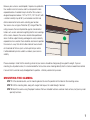
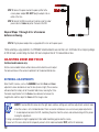
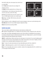
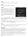
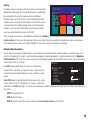
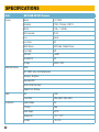
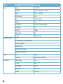
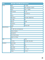
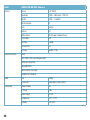
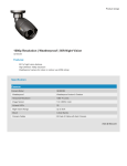
User Manual
SDI CAMERAS
1080p High Definition SDI Security Cameras
for use with SDI DVRs
1
Thank You for Choosing a Q-See Product!
All of our products are backed by a conditional service warranty covering all hardware for 12 months from the date of purchase.
Additionally, our products also come with a free exchange policy that covers all manufacturing defects for one month from the date of
purchase. Permanent upgrading service is provided for the software and is available at www.Q-See.com.
Be certain to make the most of your warranty by completing the registration form online. In addition to warranty and technical support
benefits, you’ll receive notifications of product updates along with free downloadable firmware updates for your DVR. Register today
at www.Q-See.com!
Please see the back of this manual for exclusions.
© 2012-2013 Q-See. Reproduction in whole or in part without written permission is prohibited. All rights reserved. This manual
and software and hardware described herein, in whole or in part, may not be reproduced, translated, or reduced to any machinereadable form without prior written approval.
Trademarks: All brand names and products are trademarks or registered trademarks of their respective owners.
Q-See is a registered trademark of DPS, Inc.
Disclaimer: The information in this document is subject to change without notice. The manufacturer makes no representations or
warranties, either express or implied, of any kind with respect to completeness of its contents.
Manufacturer shall not be liable for any damages whatsoever from misuse of this product.
2
About this Manual
This manual is written for the Q-See’s high-definition SDI cameras for use with DVRs featuring SDI technology. This manual was
accurate at the time it was completed. However, because of our ongoing effort to constantly improve our products, additional features
and functions may have been added since that time and on-screen displays may change. We encourage you to visit our website at
www.Q-See.com to check for the latest product announcements. You can also find technical details for your specific camera on its
product page at our site.
Throughout the manual we have highlighted warnings and other important information that will assist you in operating your new
system in a safe and trouble-free manner. Please take the time to read and follow all instructions and pay attention to alerts as
shown below:
IMPORTANT! Red boxes with this icon indicate warnings. To prevent possible injury or
damage to the product, read all warnings before use.
NOTE! Text in blue boxes with the Information icon offer additional guidance and explanations
about how to make the most out of your system.
DMSDI Rev. 2.5.1 5/20/14
3
TABLE OF CONTENTS
INTRODUCTION5
INSTALLATION6
Positioning Your Camera
6
Mounting the Camera
7
Connecting the Camera to a Security DVR System
9
Adjusting Zoom and Focus
10
Controlling Your Camera
11
OPERATION12
Setup Menu
12
Lens13
Exposure13
White Balance
15
Day/Night Mode
16
Special17
Image Adjust
19
Reset19
TROUBLESHOOTING20
SPECIFICATIONS21
Q-SEE PRODUCT WARRANTY
4
24
INTRODUCTION
For your safety
To prevent damage to your Q-See product or injury to yourself or to others, read and understand the following safety precautions in
their entirety before installing or using this equipment.
WARNING! ELECTRIC SHOCK RISK!
nCare should be taken during transportation, storage and installation of this camera to avoid rough handling, dropping, or other
abuse in order to prevent damage to the optics or components inside the camera.
nCamera should be installed in accordance with electrical standards including keeping the camera and cable away from high
voltage, using a surge protector and using only the rated power supply.
nDo not use strong or abrasive cleaners on camera body or lens. Use a damp cloth for cleaning the housing and a lens cloth for the
optics.
nDo not attempt to disassemble the camera. Only authorized, trained technicians should service this camera.
nCameras should not be immersed in water and should be mounted in a sheltered location. Do not point camera directly at the sun
or other strong light source.
IMPORTANT! When selecting a surge protector, it is STRONGLY recommended to use one that is UL-1449 rated,
for a clamping voltage of 330 or lower, a Joule rating of at least 400 and a response time of 10 nanoseconds or less.
Product Features
These cameras offer the following features:
nDigital SDI technology
nDigital 1080p high definition resolution.
nState-of-the-art IR cut filter to ensure accurate color representation during the day and sharper images at night.
nLow light and infrared operation. The camera takes advantage of even low levels of ambient lighting to produce images with color.
nAutomatically switches to infrared (black and white) mode when no light is detected.
nInfrared illumination ranging from 45 to 90 feet, depending on model
nOn-Screen Display (OSD) allows you to configure some cameras using the built-in thumbstick when connected to a monitor.
nCustomizable settings: WDR (wide dynamic range), White Balance, Backlight Compensation, Shutter Speed, etc.
nHigh Spotlight Back Light Compensation. Excessive light, such as headlights, can be masked if desired.
5
INSTALLATION
POSITIONING YOUR CAMERA
When installing your camera, it is important to select a proper site not only for field of view, but for other considerations as well:
Distance from viewing/recording device. The further the camera is from the DVR or monitor, the higher the chances
of signal degradation. UL-Listed shielded RG59 or RG6 must be used at all times to provide a high definition signal. The camera’s
power supply should be located as near to the camera as possible when the distance exceeds 200’ as the power level will drop over
extended distances resulting in a decrease in video quality and IR LED range.
Do not place near high voltage wires or other sources of electrical interference. Electrical interference will
degrade the quality of the signal.
Place camera out of reach to avoid damage.
Avoid direct exposure to weather. Do not place the camera where rain or snow will hit the lens directly nor should the
camera be placed so that the sun or bright light shines directly into the lens. Indoor cameras should never be placed outside.
Weatherproof cameras will not work when submerged. Ensure that all power and video connections are not directly exposed to water
and are protected from the elements.
Do not place camera behind a window. The IR LEDs act like a flashlight and will create a reflection that will obscure
events on the other side of the glass.
Light levels should be approximately the same between camera and target area. A camera in a brightly-lit
area looking into a shaded area, or vice versa, will produce inadequate results.
Avoid areas with high vibration. Vibrations from heavy equipment or machinery adjacent to the wall that the camera is
mounted on will cause the camera to shake and the resulting video will also be shaky.
The above are guidelines and the optimal location for your camera will depend on your unique circumstances. As a general rule, the
locations highlighted in green in the picture on the following page indicate the best locations to mount your camera. Both locations
are sheltered from rain or snow and offer good sight lines to allow your camera to monitor a wide area.
6
Because your camera is weatherproof, it requires less protection
than weather-resistant cameras and it can be placed in more
exposed locations if needed. Keep in mind that this camera is
designed to operate between 14°F to 122°F (-10°C to 50°) with
a relative humidity of up to 95%) and consider wind chill and
other environmental factors when selecting your location.
Your camera has an Ingress Protection (IP) rating of IP66. This
rating measures the level of protection against environmental
factors such as dust and moisture getting into the inner workings
of the camera. However, the camera should not be positioned
where it will be subject to being submerged in water, or directly
exposed to rain or snowfall. Care should be also taken to position
the camera in a way that will not allow moisture to accumulate
on the outside of the lens (such as from sprinklers) or where
it will be blocked by icicles as both can reduce your camera’s
visibility.
Please also keep in mind that the mounting surface for your camera should be strong enough to support its weight. If you are
mounting to a drywalled surface, it is recommended that at least one screw should go directly into the structural wood frame behind
it ensure that it cannot be easily dislodged from its position - either by accident or by vandals.
MOUNTING THE CAMERA
STEP 1. At the desired location, use the mounting bracket to mark the position for the holes for the mounting screws
STEP 2. Drill the mounting holes, along with a larger hole to pass the cable through if desired.
STEP 3. Mount the camera using the proper hardware. We have included fasteners usable on most surfaces, but you may need
specialty fasteners.
7
OTHER ENVIRONMENTAL CONSIDERATIONS
Most users prefer to operate their security systems with the DVRs recording only when motion is detected. This provides the most
efficient use of the hard drive’s capacity, plus making it easier for a recording to be located. However, if the camera’s location has a lot of
“environmental” motion, such as a fan, wind, or the like, you will receive a lot of “false alarms.” Usually, these events can be avoided by
simply adjusting the placement of the camera. Other situations may require some fine-tuning of your settings. Your DVR’s manual covers
these settings in detail, but some easily avoidable situations are presented below:
TV/Computer Screens. If the camera can see a video screen, it will trigger a motion alarm any time the screen changes, whether there
is a video or simply a screen saver. Most Q-See DVRs have the ability to let you mask out the area, or turn off sensitivity to motion in
specific parts of their field of view.
Fans/Machinery. Motion is motion and if machinery within the camera’s field of view starts automatically, it will cause an alert.
Similarly, if the camera is mounted on a wall with machinery on the other side that causes it to vibrate, that can also cause it to detect
motion. Moving machinery within the camera’s field of view may be masked off as mentioned above, or motion detection may be turned
off for that channel. If there is another camera that covers access to the area where the machinery is located, you can set it so that
the first camera will only be recording when triggered by a motion event detected by this second camera. See your DVR’s manual for
specifics on altering these settings.
Bugs. An occasional insect flying through the field of view is usually not enough to trigger an alert. However, some flying insects are
attracted to infrared light and will swarm the camera. This is usually a temporary situation that occurs at only a certain time of the year.
Lighting the area with yellow “bug light” of sufficient brightness can keep the camera operating in daylight mode and keep the infrared
LEDs turned off. A second solution is to set the channel to record all the time, and turn motion detection off at night until “bug season” is
over. Reducing the motion sensitivity can also reduce alerts as can using another camera to trigger recording as described above.
Additionally, keep your cameras clear of spider webs as the movement of the webs due to wind or critters in the web will cause an alert.
The reflection of the infrared off the webs and back into the camera will also reduce the night vision range.
Snow/Rain. As with bugs, this is usually a seaonal event and may require motion detection to be temporarily disabled to avoid false
alarms. However, positioning the camera further under shelter, such as closer to the wall and away from the edge of the eaves, can make
the rain or snow too small for the camera to notice. Adjusting motion sensitivity may also help in some situations.
8
CONNECTING THE CAMERA TO A SECURITY DVR SYSTEM
IMPORTANT! Even though your camera uses the same BNC video connector found on
conventional analog cameras, you CANNOT utilize an SDI camera with a conventional DVR, nor
can you use analog cameras with an SDI DVR.
It is also not possible to connect an SDI camera to standalone monitor.
If you are upgrading to an SDI system and already have shielded RG59 or RG6 cables installed, you may
utilize those cables, only replacing camera and DVR. Your SDI system will not work with non-shielded cables.
Additionally, your cables should not have any extensions. A single, continuous cable with the only connections
being those used to attach the camera and the DVR to the cable will allow for the best video.
STEP 1. Connect the BNC and power leads from the camera to the
matching connectors on one end of the power and video cable.
CAMERA
STEP 2. For multi-camera packs, connect the power lead on the
other end of the cable to the plug from the power splitter. Or, if
IMPORTANT! When connecting the power and video cable between the camera and the DVR, the
“male” power end (red plug in the illustration) connects to the matching power lead on the camera.
IMPORTANT! Some camera models have two video leads. One is for SDI video, while the other
is used during the installation process to allow the user to adjust the camera’s field of view, including
zoom and focus. This second lead is usually thinner than that for the SDI. Both leads will be identified
with labels as well as embossed text on their ends. Use the CVBS lead with a camera tester - a battery operated
video screen that will show what the camera sees. Always use the lead marked SDI with your SDI DVR.
your package includes a power distribution panel, connect the
power lead to one of the power jacks on the panel. Proceed to
Step 4, below.
For single camera packages, connect the power lead to the
power adapter itself. In this case, you may skip to Step 4.
9
STEP 3. Connect the power lead on the power splitter to the
camera power adapter. DO NOT plug the adapter into an
outlet at this time.
STEP 4. Connect the BNC connector on the other end of the video/
power cable to a Video In port on the back of the DVR.
Repeat Steps 1 through 4 for all cameras
before continuing.
STEP 5. Plug the power adapter into a surge protector* or turn on the power panel.
*When selecting a surge protector, it is STRONGLY recommended to use one that is UL-1449 rated, for a clamping voltage
of 330 or lower, a Joule rating of at least 400 and a response time of 10 nanoseconds or less.
ADJUSTING ZOOM AND FOCUS
Varifocal model cameras only.
Certain camera models feature varifocal lenses which allow the user to adjust
the zoom and focus of the camera to optimize it for the desired field of view.
EXTERNAL ADJUSTMENTS
Some “bullet” cameras, such as the QH8005B, have their Zoom and Focus
adjustment screws located on or near the lens (shown at right). These cameras
will come from the factory set for the widest field of view, meaning that it has
the lowest magnification. Turn the Zoom screw clockwise to increase the
magnification and then adjust the Focus until the image is clear.
HINT! It can be difficult to know what the right zoom and focus settings are and these adjustments are best made
when the camera is at its intended location. There are several methods one can use to ensure proper adjustments:
1. A second person located at the DVR, monitoring the picture from the camera and communicating with the person
making the adjustments.
2. Using a smartphone running the appropriate Q-See mobile monitoring app to view the camera.
3. Use of an LCD camera tester which temporarily connects to the video lead labelled TEST (not the HD video lead).
10
INTERNAL ADJUSTMENTS
While most “bullet”-style cameras such as the QH8005B will have their lens
adjustments on the outside, dome cameras like the QH8006D and QH8008D
and the bullet-style camera QH8005B have their adjustments inside their cases,
right on the lens assembly itself.
Dome Cameras
There will be screws on the camera’s case that will be needed to be unscrewed
in order to remove the upper portion (the portion covering the lens).
The adjustment screws are located below the camera’s lens. They MUST be loosened using a small screw driver before attempting
to adjust the zoom and focus otherwise the screws will snap off and the camera will no longer be able to be adjusted. Be certain to
gently tighten the screws once you have set your desired zoom and focus as vibrations may otherwise cause the camera to slip out of
adjustment.
IMPORTANT! Before adjusting the zoom and focus on the camera, you MUST first loosen the screws on the
respective adjustment rings. Failure to do so will result in damage to the camera.
Bullet Cameras
The adjustment knobs will be located on the lens assembly inside the camera
so the lens cover must be first removed to gain access. If there is a removable
sunshade, it should also be temporarily removed for easier access to the lens
cover.
Once the lens cover has been removed, you will see the adjustment screws
located behind the cameras lens. They MUST be loosened using a small screw
driver before attempting to adjust the zoom and focus otherwise the screws will
snap off and the camera will no longer be able to be adjusted. Be certain to gently
tighten the screws once you have set your desired zoom and focus as vibrations
may otherwise cause the camera to slip out of adjustment. When replacing the
lens cover take care to make sure there aren’t any fingerprints or dust on the
inside that will obscure the lens.
11
CONTROLLING YOUR CAMERA
The camera’s on-screen menu is accessed by the multi-function button
attached to the camera cable.
To access the on screen display, press the multi-function button. This will bring
up the menu on your system’s monitor or other attached display. This button also
acts as the “Enter” button when setting your parameters.
Navigate through the menu using the directional controls. The cable-mounted
multi-function button acts as a miniature joystick allowing you to move up,
down, left or right through the menu and submenus.
The next chapter describes the operation of the On-Screen Display.
12
Cable-Mounted
Multi-Function
Button
OPERATION
The On Screen Display (OSD) built into your camera allows you to control almost every aspect of how it captures images. Using the
built-in menus, you can optimize exposure, gain, backlight, white balance and other functions to best fit the location and use of your
camera. It should be noted that these settings must be made at the camera itself and they cannot be set remotely. When used with a
security DVR system, what you see on the screen will be what is recorded - including the OSD menu. In fact, use of the OSD can trigger
motion detection so it may be advisable to temporarily disconnect/disable alarms or notifications when working in the OSD menu.
Settings will be stored on the camera even in the event of power loss. Once power is restored, the camera will continue to operate
according to your settings. You can revert to the factory default settings by selecting “Reset” in the menu.
SETUP MENU
Pressing the multi-function button (shown on previous page) will open the OSD to the Setup Menu. The menu will appear over the
video image being delivered by the camera.
SETUP
1.LENS
MANUAL
2.EXPOSURE
3. WHITE BAL
ATW
4.DAY/NIGHT
5.SPECIAL
6. IMAGE ADJUST
7.RESET
8.EXIT
To change a setting, use the button to scroll to the desired item
until it is indicated by the arrow and press right or left to select
the desired value. Menu options with a “ ” indicate that there is
a submenu. Clicking on such an item by pushing in the button
will take you to the desired submenu.
This menu is embedded on the chipset that processes the
images coming to the camera, This chipset is used in numerous
cameras with various capacities and not all functions will work
on this camera.
Some cameras will have a menu that differs slightly than the one shown above. In this case, the Lens options will be replaced by the
Language menu - which will not appear as an option in the Special menu. With slight differences in appearance, the other menus
on these cameras will operate as shown
In most of the submenus, you can use the Return option to go back to the main Settings menu by selecting RET. You may also leave
the menu completely by selecting EXIT.
IMPORTANT! Your camera will retain your settings in case of power loss, but only if you exit the
menu using the EXIT option either from the Setup menu or from within a submenu.
13
LENS
This feature is for use on cameras using DC (Defocus Control) lenses. Neither the default setting, Manual, nor the DC setting will have
any effect upon your camera.
EXPOSURE
This selection includes several submenus which cover how your
camera handles different lighting conditions and levels.
Shutter
EXPOSURE
SHUTTERAUTO
AGC
SENS-UPOFF
WDR
OFF
DEFOGOFF
BACKLIGHTOFF
RETURNRET
6
This adjusts the shutter speed from 1/30 to 1/10,000 second (up to
1/50,000 of a second on some models) with the video’s light level
getting darker as the speed increases. In areas which are constantly
brightly lit, you will want to use a faster speed. There is also an
FLK setting to reduce flicker or camera rolling - especially in areas
illuminated by fluorescent light. The 2x setting is a Digital Slow Shutter (DSS) format which improves the light sensitivity of the camera
by allowing two times the normal amount of light into the camera, extending its usable range in low light conditions.
AGC
AGC, or Automatic Gain Control, is primarily used to increase the brightness of the video image when the area is poorly lit.
Settings range from 0 to 16 with the default being 6. Use of this feature can increase the “noise” in the video signal as the camera
compensates.
Sens-Up
This technology also allows the camera to better use available light in order to provide a clear image. It does so by increasing the time
that the shutter is open in order to gather more light. You can set this between 2x and 10x. The drawback is that motion will become
increasingly blurry and this is specifically recommended against if the camera is being used to capture a license plate or other
identifying detail. Please note that this feature is disabled when the shutter speed (above) is set to anything other than Auto or 1/30.
14
WDR
Wide Dynamic Range, or WDR, is a process where the camera
captures an image both with short and a long exposure in order
to balance the darker areas with the brighter, highlighted areas
to maximize the visibility of details in both areas. It differs from
Backlight Compensation (discussed later) in that the camera
WDR Off
WDR On
attempts to adjust the contrast in both areas. This is best used in
areas with uneven lighting. The settings are High, Medium and Low. This option may also be disabled depending on your Exposure
settings.
Defog
For use in areas frequently obscured by haze or fog, the Defog filter adjusts the camera’s contrast in order to provide clearer details.
This can also be used when the subject is very brightly lit. You can set it to High, Medium or Low.
Backlight
This selection consists of two submenus which allow you to
optimize camera performance in areas which are lit from behind.
BLC
GAINMIDDLE
BLC stands for Back Light Compensation. This first option
AREAON
is designed for areas such as a room where the camera
DEFAULT
faces a window through which sunlight enters. It allows you
RETURNRET
to compensate using low, middle or high gain which will
progressively brighten the area on the screen to compensate for
the relative darkness of the area lit from behind. You can adjust
the size of the area, along with its position from within the Area option. Pushing up or left will shrink the area, while down or right will
enlarge it. It can then be positioned as desired.
HSBLC, or High Spotlight Back Light Compensation is for
situations where lights will be shining towards the camera. This
is the setting used when trying to capture images of license
plates for identification. As seen in the photos on the right, the
brightest light sources are blocked by the camera allowing the
plate to be read as opposed to washed out by the headlights.
Please see our online knowledge base at www.Q-See.com/
Support for guides on how to best capture license plate images.
HSBLC Off
HSBLC On
15
Unlike the BLC setting, there are four separate areas where the user
can activate HSBLC.
Use the Select option to chose which area to configure. The
selected area will flash.
Use Display to activate or deactivate that area. Pushing in on the
control button opens a menu that allows you to move and resize the
area in the same manner as with the BLC setting.
Level adjusts the sensitivity of all the areas with a range of 1 to 100.
HSBLC
SELECTAREA1
DISPLAYON
LEVEL
40
MODE
ALL DAY
BLACK MASK
ON
DEFAULT
RETURNRET
You can set HSBLC operate constantly, or just at night using the
Mode setting. If set to Night, HSBLC will only be active when the
camera’s LEDs are on.
While the visible mask is useful in configuring the area for the camera to compensate, some users may find it distracting. Use the
Black Mask option to turn off the mask without changing the compensation settings.
Default will restore the factory settings for HSBLC.
WHITE BALANCE
There are seven modes available for determining how your camera processes and displays color:
ATW - Automatic Tracking White Balance. This is the default the camera constantly analyses and adjusts to create a neutral white
balance. Colors may be slightly underexposed but generally accurate. Several settings can be modified, but the most significant is
the Environment setting which adjusts the white balance based on the light source. Daylight generally has a bluish tint while indoor
lighting will tend towards yellow (light bulbs) or green (fluorescent).
AWC-SET - Auto White Balance Control. Using this locks in the white balance at its current level. This can be set by holding a piece of
white paper in front of the camera. Pushing the button will then establish the white balance. Use this when the lighting is constantly
changing or the area surrounding the object under observation is over- or under-lit
Indoor - This adjusts the color range to compensate for typical indoor lighting sources which have a yellowish tint.
Outdoor - Outdoor lighting generally has a bluish tint from the atmosphere so this setting adjusts for that.
Manual - This is the best option when the camera is mounted in a location with unchanging lighting. When this is selected, the user
can manually adjust the blue and red levels.
16
DAY/NIGHT MODE
Mode
This allows you to set the camera to switch automatically from day to night mode based on external lighting using the default EXT
mode, or adjusting the lighting criteria for the switch using Auto. You may also permanently set it to Color or B/W operation. Please
note that even when the camera is set to Color mode, it will switch to black and white night vision when there is no longer enough
ambient light to support color video.
AUTO - Use the Delay setting to adjust how long after a certain light level is reached before the camera switches modes. The default
is 5 seconds, but it can be delayed up to 100 seconds. The DAY NIGHT and NIGHT DAY settings allow you to set the desired
lighting threshold at where the camera will switch modes. Both use Automatic Gain Control and setting too high a level in the former
and too low a light level in the latter can produce video with too much “noise” or, the camera may not switch between modes at all.
IMPORTANT! The DAY NIGHT and NIGHT DAY operations should be tested during installation. Block the lens
for a few seconds to force a switch to night mode. Once the lens is unblocked, the camera should switch back to
day mode in less than 10 seconds. If it does not, slightly increase the threshold in the NIGHT DAY setting. A dimly
lit area or a very low iris setting may also prevent a return to day mode.
B/W - When the camera is set to operate permanently in black and white mode with non-Q-See branded DVRs, you may need to
enable Burst. This is a signal sent out by the camera even when no color information is available to allow a DVR or security video
capture cards to recognize the camera. This can be left off when using the camera with a Q-See product.
Smart IR
Dependiong on model, your camera has an effective Infrared illumination range of up to 100 feet. The LEDs around the camera’s lens
act as an infrared flashlight, invisibly lighting the area so that the camera’s optics can pick up the image. Much like a conventional
flashlight - or even a camera flash - if the subject is too close to the light source, it can get “washed out” or overexposed. Activating
the Smart IR feature allows the camera to adjust the intensity
of the LEDs to avoid detail loss. This feature should be enabled
when the camera is pointing at a wall or item that is relatively
close to it. It will also adjust when someone moves through the
area, making the feature useful for access or entry points as well
as aisles.
The gain level can be adjusted and you can designate a
particular area for the camera to adjust the IR brightness. This
area is set in the same manner as found in the Backlight menu.
Smart IR Off
Smart IR On
17
SPECIAL
The settings in the menu allow you to further customize your camera to suit your needs.
Language
You can chose from English, traditional Chinese or simplified Chinese.
Camera Title
This allows you to create and display a name for the camera as well
as position it within the image. If you are using this camera with
a Q-See DVR, please note that this display is in addition to - and
separate from - the similar display available through the DVR which
can be turned on or off within the DVR. If the camera title is enabled,
“CAM 01” will also appear in the upper right hand corner. It will
appear, along with the name you chose on any video recorded from
this camera.
CAM TITLE
0 1 2 3 4 5 6 7 8 9
A B C D E F G H I J K
L M N O P Q R S T U V
W X Y Z
( )
/ = & ~ , .
CLR
CAMERA_1
POS
END
To enter text, use the multi-function button to navigate to the desired character and then press the button to enter it and the cursor
will advance to the next position in the name. The arrow buttons will allow you to move the cursor within the camera name. You may
enter up to 15 characters.
Use the arrow keys to move within the name. When complete, click on POS to position the name within the camera’s view. Once
you’ve positioned the name, press in on the multi-function button to exit.
Mirror
Use the options in this menu to rotate your camera’s view or flip it either vertically or horizontally. This is useful in situations where
your camera cannot be positioned to provide a proper video image in the normal manner.
Motion Detection
Unlike most security cameras, your camera is capable of detecting motion by itself. If you are connecting your camera to a Q-See
security DVR, you will not need to enable this feature as the DVR itself has motion detection capabilities. We do not recommend
enabling motion detection on the camera while connected to a security DVR as it can produce adverse results by obscuring the
recorded video or generating artifacts which the DVR will interpret as motion causing it to record unnecessarily.
If you do chose to use it, there are three individually-configurable areas which you can select to notice motion. By default, items
moving within these areas will have red pixels tracking the object. You can adjust the sensitivity, size, and position of these areas
along with whether the areas themselves will appear on-screen.
18
Privacy
This allows you to set up areas within the camera’s view that will be
blocked from observation. This may be the location of a combination
lock, keypad or other area that requires privacy. Like Motion
Detection above, use of this feature is not recommended for most
situations when the camera is connected to a security DVR as it will
create artifacts on the video recording which cannot be removed.
However, users may find it to be beneficial feature when multiple
users have administrator-level access to the DVR.
PRIVACY
SELECTAREA1
DISPLAYON
COLOR2
DEFAULT
RETURNRET
There are eight areas which can be individually configured. Use Display to turn each one on or off as desired. Pressing the multifunction button will take you to the submenu where you can adjust the size and position the selected area. You can also choose
from 16 colors for the privacy area to either highlight the area, or to make it less obvious on the display.
Defective Pixel Correction
Like HD displays and monitors, digital cameras can occasionally have defective pixels. A defective pixel is more likely to occur as a
result of mishandling of the camera - whether by being dropped, or attempted vandalism. Using the options within the Defective
Pixel Correction (DPC) menu, the camera can be set to automatically compensate for defective pixels and the user can attempt to
correct pixels which are “stuck on.”
DEFECT
Live DPC, when enabled, allows the camera to automatically
compensate for a pixel that is inoperative. You can adjust the level
of sensitivity, but overcompensating can cause a decline in image
quality.
LIVE DPC
ON
LEVEL
STATIC DPC
OFF
START
LEVEL
RETURNRET
30
4
Static DPC allows the user to attempt to reset pixels which may be
stuck in either the “on” or “off” position. The camera’s shutter will
need to be set to AUTO (see Page 11). You will also need to have a bright flashlight or other light source available to shine directly at
the camera.
STEP 1. Enable static DPC
STEP 2. Adjust the level
STEP 3. Shine the light at the camera and push the multi-function button to start the DPC.
19
IMAGE ADJUST
Use these settings to fine-tune your video by adjusting brightness, color levels, and noise reduction among other options.
3DNR
3DNR, which is short for 3-D Noise Reduction, compares a sequence of video images over a period of time and blends them to
reduce graininess. When enabled, there are individual settings for day (D) and night (N) video. Use these sliders to reduce the amount
of motion blur that can occur due to noise reduction.
IMAGE ADJUST
Sharpness
3DNRON
There are two sliders allowing you to adjust the sharpness of the
SHARPNESS
video for day and night images.
BRIGHTNESS
30
GAMMAUSER
Brightness
BLUE GAIN
50
Adjust this using the slider.
RED GAIN
50
LENS SHADING
OFF
Gamma
NTSC/PALNTSC
This differs from brightness by adjusting the luminance of the video
RETURNRET
image by reducing “noise” while still keeping blacks black and
whites white. This can be adjusted from .45 (lightest) to 1(darkest),
or left at the User (automatic) setting.
Lens Shading
Correction Off
Blue/Red Gains
You can individually adjust the blue and red channels using these
sliders.
Lens Shading
Shading refers to the tendency for the corners of an image to be
darker than the center. When shading correction is enabled, the
image will be electronically corrected to lighten the corners.
Lens Shading
Correction On
NTSC/PAL
These are two of the television video modes used globally. If you are using a VGA or HDMI screen to view your DVR you will not need
to change this setting. NTSC is used throughout North America and parts of South America, while PAL is used elsewhere in South
America, Europe (except for France), Oceania and parts of Africa and Asia.
RESET
This menu allows you to reset everything back to the factory settings. It also displays the firmware version of the camera.
20
TROUBLESHOOTING
Problem
Solution
No picture or unstable image
Check both the power and video connections to the camera.
Cup hand over lens to see if IR LEDs illuminate with a faint red glow.
The on-screen image is blurry.
1. Check the camera focus.
2. Check for fingerprints or dirt on the lens.
3. Check menu settings.
The on-screen image is dim.
1. Check for fingerprints or dirt on the lens.
2. Check monitor settings
3. Check camera SHUTTER/AGC settings.
The on-screen image is dark.
1. Adjust the monitor contrast settings.
2. Adjust camera SHUTTER/AGC settings.
The on-screen image is dark only part of the day.
The sun may shine directly into the camera which will backlight the
subjects. Adjust BLC to compensate or reposition camera.
The on-screen image color is incorrect.
Check camera WHITE BAL setting.
The on-screen image has a lot of noise.
1. Check camera Noise Reduction settings
2. Check camera auto gain setting in SHUTTER/AGC menu.
3. If the camera is mounted on a metal building, you will need to use a
rubber gasket or wood block to separate the camera from the metal.
No motion detection or privacy frames.
Check whether those settings have been enabled.
The screen flickers.
Camera may be facing sun, television or computer monitor.
The IR LEDs will not light up
1. Check the power connection to the camera.
2. Power supply may need to be located closer to camera.
3. Change DAY/NIGHT mode on camera to AUTO or B/W mode
The camera is not working properly, is hot, smells or is
producing smoke.
DISCONNECT CAMERA FROM POWER SUPPLY
IMMEDIATELY!
1. Check that correct power supply is in use.
2. Send camera out for repair.
21
SPECIFICATIONS
Model
QH7004B HD SDI Camera
Camera
Sensor
1/3” CMOS
Resolution
1280 x 720 pixels / 800 TVL
Shutter
1/50s ~ 1/67500s
Min Illumination
0 LUX
Lens
3.6mm
Lens Driver
DC
White Balance
ATW, Indoor, Outdoor, Manual
Day & Night
ICR
S/N Ratio
>52dB
Infrared LEDs
30
IR range
80 feet / 24M
Advanced Features
3DNR
BLC, HSBLC, Area, Level Compensation
Sharpness, Brightness
Adjustable WDR
Rotate, Mirror, Flip Image
Supports Lens Shading
Video
Environment
22
Size
720p
Frame Rate
30fps (60Hz), 25fps (50Hz)
Indoor/Outdoor
Yes
IP Rating
IP66
Power Supply
DC12V
Temperature
14°F - 122°F
Humidity
10%-90%
Model
QH8003B HD SDI Camera
Camera
Sensor
1/3” CMOS
Resolution
1920 x 1080 pixels / 1000 TVL
Shutter
1/50s ~ 1/67500s
Min Illumination
0 LUX
Lens
4.2mm
Lens Driver
DC
White Balance
ATW, Indoor, Outdoor, Manual
Day & Night
ICR
S/N Ratio
>50dB
Infrared LEDs
30
IR range
45 feet / 15M
Advanced Features
3DNR
BLC, HSBLC, Area, Level Compensation
Sharpness, Brightness
Adjustable WDR
Rotate, Mirror, Flip Image
Supports Lens Shading
Video
Environment
Size
1080p
Frame Rate
30fps (60Hz), 25fps (50Hz)
Indoor/Outdoor
Yes
IP Rating
IP66
Power Supply
DC12V
Temperature
14°F - 122°F
Humidity
10%-90%
23
Model
QH8005B & QH8011B HD SDI Cameras
Camera
Sensor
1/3” CMOS
Resolution
1920 x 1080 pixels / 1000 TVL
Shutter
1/50s ~ 1/67500s
Min Illumination
0 LUX
Lens
3.3mm to 12mm
Auto Iris
DC
White Balance
ATW, Indoor, Outdoor, Manual
Day & Night
ICR
S/N Ratio
>50dB
Infrared LEDs
36
IR range
100 feet / 30M
Advanced Features
3DNR
BLC, HSBLC, Area, Level Compensation
Sharpness, Brightness
Adjustable WDR
Rotate, Mirror, Flip Image
Supports Lens Shading
Video
Environment
24
Size
1080p
Frame Rate
30fps (60Hz), 25fps (50Hz)
Indoor/Outdoor
Yes
IP Rating
IP66
Power Supply
DC12V
Temperature
14°F - 122°F
Humidity
10%-90%
Model
QH8006D & QH8008D HD SDI Cameras
Camera
Sensor
1/3” CMOS
Resolution
1920 x 1080 pixels / 1000 TVL
Shutter
1/50s ~ 1/67500s
Min Illumination
0.1 LUX
Lens
3.3mm to 12mm
Auto Iris
DC
White Balance
ATW, Indoor, Outdoor, Manual
Day & Night
ICR
S/N Ratio
>50dB
Infrared LEDs
30
IR range
100 feet / 30M
Advanced Features
3DNR
BLC, HSBLC, Area, Level Compensation
Sharpness, Brightness
Adjustable WDR
Rotate, Mirror, Flip Image
Supports Lens Shading
Video
Environment
Size
1080p
Frame Rate
30fps (60Hz), 25fps (50Hz)
Indoor/Outdoor
Yes
IP Rating
IP66
Power Supply
DC12V
Temperature
14°F - 122°F
Humidity
10%-90%
25
Model
QH8007D HD SDI Camera
Camera
Sensor
1/3” CMOS
Resolution
1920 x 1080 pixels / 1000 TVL
Shutter
1/50s ~ 1/67500s
Min Illumination
0
Lens
3.6mm
Auto Iris
DC
White Balance
ATW, Indoor, Outdoor, Manual
Day & Night
ICR
S/N Ratio
>50dB
Infrared LEDs
24
IR range
60 feet / 20M
Advanced Features
3DNR
BLC, HSBLC, Area, Level Compensation
Sharpness, Brightness
Adjustable WDR
Rotate, Mirror, Flip Image
Supports Lens Shading
Video
Environment
26
Size
1080p
Frame Rate
30fps (60Hz), 25fps (50Hz)
Indoor/Outdoor
Yes
IP Rating
IP66
Power Supply
DC12V
Temperature
14°F - 122°F
Humidity
10%-90%
QUESTIONS OR COMMENTS? CONTACT US
24/7 TECHNICAL RESOURCES,
KNOWLEDGE BASE AND MORE
www.Q-See.com/Support
Q-SEE PRODUCT WARRANTY
Q-See is proud to back all of our products with a conditional service warranty covering all hardware for 12 months from the date of
purchase. Additionally, our products also come with a free exchange policy that covers all manufacturing defects for one month from
the date of purchase. Permanent upgrading service is provided for the software.
Liability Exclusions:
Any product malfunction or abnormalities in operation or damage caused by the following reasons are not within the free service
scope of our company:
1. Equipment damage caused by improper operation.
2. Improper equipment operation environment and conditions (e.g., improper power, extreme environmental temperatures,
humidity, lightning and sudden surges of electricity).
3. Damage caused by acts of nature (e.g., earthquake, fire, etc).
4. Equipment damage caused by the maintenance of personnel not authorized by Q-See.
5. Product sold over 12 months ago.
In order to fulfill the terms of your warranty, you must complete the registration process after purchasing our product. To do this,
simply fill out the User’s Information Card on our website at www.Q-See.com
27
Digital
Digital Peripheral
Peripheral Solutions,
Solutions, Inc.
Inc.
8015
8015 E.
E. Crystal
Crystal Drive
Drive
Anaheim,
Anaheim, CA
CA 92807
92807
28