1
SRPL8
Server System
Product Guide
Order Number: A49445-001
Disclaimer
Intel Corporation (Intel) makes no warranty of any kind with regard to this material, including, but not limited to, the implied
warranties of merchantability and fitness for a particular purpose. Intel assumes no responsibility for any errors that may
appear in this document. Intel makes no commitment to update nor to keep current the information contained in this
document. No part of this document may be copied or reproduced in any form or by any means without prior written
consent of Intel.
An Intel® product, when used in accordance with its associated documentation, is "Year 2000 Capable" when, upon
installation, it accurately stores, displays, processes, provides, and/or receives date data from, into, and between the
twentieth and twenty-first centuries, including leap year calculations, provided that all other technology used in combination
with said product properly exchanges date data with it.
† Third party brands and names are the property of their respective owners.
Copyright © 2001, Intel Corporation. All rights reserved.
Contents
Part I: User’s Guide ......................................................................................................... 11
1 Chassis Description
Chassis Feature Summary ................................................................................................. 14
Chassis Front Controls and Indicators ....................................................................... 15
Chassis Back Controls and Features......................................................................... 17
Peripherals ......................................................................................................................... 18
3.5-inch Diskette Drive............................................................................................... 18
3.5-inch Hard Drive Bays ........................................................................................... 18
5.25-inch Removable Media Device Bay ................................................................... 18
Hot-Swap Power Supplies .................................................................................................. 19
System Cooling .................................................................................................................. 19
2 Boardset Description
Boardset Features.............................................................................................................. 22
Processor Overview................................................................................................... 24
Memory Overview...................................................................................................... 25
DIMM Installation Sequence ...................................................................................... 26
Peripherals ......................................................................................................................... 27
Super I/O Chip........................................................................................................... 27
Add-In Board Slots ............................................................................................................. 27
Video .................................................................................................................................. 27
SCSI Controller .................................................................................................................. 28
IDE Controller..................................................................................................................... 28
Keyboard and Mouse ......................................................................................................... 28
Server Management........................................................................................................... 29
Front Panel Controller (FPC) ..................................................................................... 30
Hot-swap Controller (HSC) ........................................................................................ 30
System Security ................................................................................................................. 31
Password Protection.................................................................................................. 31
Secure Boot Mode ..................................................................................................... 31
Boot Sequence Control.............................................................................................. 31
Boot Without Keyboard.............................................................................................. 32
Locked Power and Reset Switches............................................................................ 32
Diskette Write Protect ................................................................................................ 32
Video Blanking........................................................................................................... 32
Emergency Management Port (EMP) ........................................................................ 32
iii
3 Configuration Software and Utilities
Hot Keys............................................................................................................................. 34
Power-on Self Test (POST)................................................................................................ 34
Using BIOS Setup .............................................................................................................. 35
Record Your Setup Settings ...................................................................................... 35
If You Cannot Access Setup ...................................................................................... 35
Starting Setup............................................................................................................ 36
Setup Menus ............................................................................................................. 36
Main Menu................................................................................................................. 38
Advanced Menu......................................................................................................... 41
Security Menu............................................................................................................ 45
Server Menu .............................................................................................................. 46
Boot Menu ................................................................................................................. 49
Exit Menu................................................................................................................... 50
Using the System Setup Utility (SSU)................................................................................. 51
When to Run the SSU ............................................................................................... 51
What You Need to Do................................................................................................ 52
Running the SSU ....................................................................................................... 52
Customizing the SSU................................................................................................. 55
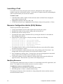
Launching a Task ...................................................................................................... 56
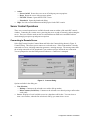
Resource Configuration Add-In (RCA) Window ......................................................... 56
Multiboot Options Add-In ........................................................................................... 57
Security Add-In .......................................................................................................... 57
System Event Log (SEL) Viewer Add-In .................................................................... 58
Sensor Data Record (SDR) Manager Add-In ............................................................. 60
Field Replaceable Unit (FRU) Manager Add-In.......................................................... 61
Exiting the SSU.......................................................................................................... 63
Direct Platform Control (DPC) Console .............................................................................. 63
How the DPC Console Works .................................................................................... 63
DPC Console Requirements ...................................................................................... 65
Setting Up the Server for the EMP............................................................................. 66
Main DPC Console Window....................................................................................... 67
Server Control Operations ......................................................................................... 68
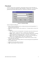
Phonebook ................................................................................................................ 71
Management Plug-Ins................................................................................................ 72
FRU and SDR Load Utility .................................................................................................. 72
When to Run the FRUSDR Load Utility...................................................................... 73
What You Need to Do................................................................................................ 73
How You Use the FRUSDR Load Utility..................................................................... 73
Cleaning Up and Exiting ............................................................................................ 76
Upgrading BIOS ................................................................................................................. 77
Preparing for the Upgrade ......................................................................................... 77
Upgrading BIOS......................................................................................................... 78
Recovering BIOS ....................................................................................................... 79
Changing BIOS Language ......................................................................................... 79
Using the Firmware Update Utility ...................................................................................... 80
Running the Firmware Update Utility ......................................................................... 80
iv
Contents
Installing Video Drivers....................................................................................................... 80
Using the QLogic SCSI Utility ............................................................................................. 80
Running the SCSI Utility ............................................................................................ 80
4 Hot-Swapping Fans, SCSI Hard Drives, and Power Supplies
Tools and Supplies Needed................................................................................................ 81
Equipment Log .......................................................................................................... 81
Hot-Swapping Fans ............................................................................................................ 82
Hot-Swapping a SCSI Hard Drive....................................................................................... 84
Hot-Swapping Bays ................................................................................................... 84
SCSI SCA Hard Disk Drives ...................................................................................... 84
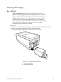
Hot-Swapping Power Supplies ........................................................................................... 88
Hot-Swapping a Power Supply .................................................................................. 88
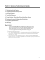
Part II: Service Technician’s Guide ........................................................................... 91
5 Working Inside the System
Tools and Supplies Needed................................................................................................ 93
Safety: Before You Remove Server Covers ...................................................................... 93
Warnings and Cautions ...................................................................................................... 94
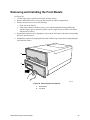
Removing and Installing the Front Bezels .......................................................................... 95
Removing and Installing Server Covers.............................................................................. 96
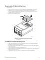
Removing the PCI Bus Hot-Plug Cover ..................................................................... 97
Installing the PCI Bus Hot-Plug Cover ....................................................................... 97
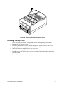
Removing the Top Cover ........................................................................................... 98
Installing the Top Cover ............................................................................................. 99
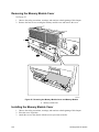
Removing the Memory Module Cover...................................................................... 100
Installing the Memory Module Cover........................................................................ 100
Fan Array Housing ........................................................................................................... 101
Removing the Fan Array Housing ............................................................................ 101
Installing the Fan Array Housing .............................................................................. 101
LCD Module ..................................................................................................................... 102
Removing the LCD Module...................................................................................... 102
Installing the LCD Module........................................................................................ 103
Profusion Carrier Tray ...................................................................................................... 104
Removing the Profusion Carrier Tray....................................................................... 104
Installing the Profusion Carrier Tray......................................................................... 104
Front Panel Controller Board ............................................................................................ 106
Removing the Front Panel Controller Board ............................................................ 106
Installing the Front Panel Controller Board .............................................................. 106
Add-In Boards .................................................................................................................. 108
Installing/Replacing an Add-In Board ....................................................................... 108
Removing an Add-In Board...................................................................................... 111
I/O Riser Board ................................................................................................................ 111
Removing the I/O Riser Board ................................................................................. 111
Installing the I/O Riser Board ................................................................................... 112
SRPL8 Server System Product Guide
v
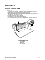
PHP LED Board ............................................................................................................... 113
Removing a PHP LED Board ................................................................................... 113
Installing a PHP LED Board..................................................................................... 114
I/O Tray ............................................................................................................................ 114
Removing the I/O Tray............................................................................................. 114
Installing the I/O Tray............................................................................................... 115
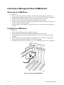
Interchassis Management Bus (ICMB) Board................................................................... 116
Removing the ICMB Board ...................................................................................... 116
Installing the ICMB Board ........................................................................................ 116
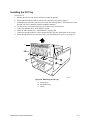
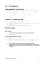
AC Filter and Cable .......................................................................................................... 117
Removing the AC Filter and Cable........................................................................... 117
Installing the AC Filter and Cable............................................................................. 117
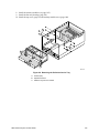
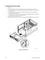
Peripheral Bay.................................................................................................................. 117
Removing the Peripheral Bay .................................................................................. 117
Installing the Peripheral Bay .................................................................................... 118
Peripheral Bay Backplane ................................................................................................ 119
Removing the Peripheral Bay Backplane................................................................. 119
Installing the Peripheral Bay Backplane................................................................... 120
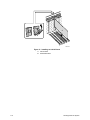
Peripheral Bay Blind Mate Board...................................................................................... 121
Removing the Peripheral Bay Blind Mate Board ...................................................... 121
Installing the Peripheral Bay Blind Mate Board ........................................................ 123
Diskette Drive ................................................................................................................... 124
Removing the Diskette Drive ................................................................................... 124
Installing the Diskette Drive ..................................................................................... 125
Peripheral Drives.............................................................................................................. 126
Installing a 5.25-inch Peripheral in the Front Bay..................................................... 126
Removing a 5.25-inch Peripheral from the Front Bay .............................................. 128
6 Upgrading Boardset Components
Tools and Supplies Needed.............................................................................................. 129
Warnings and Cautions .................................................................................................... 130
Cache Coherency Filters: Removing and Installing ......................................................... 132
Removing the Cache Coherency Filters................................................................... 132
Installing the Cache Coherency Filters..................................................................... 133
Processor Retention Bracket: Removing and Installing ................................................... 134
Removing the Processor Retention Bracket ............................................................ 134
Installing the Processor Retention Bracket .............................................................. 135
Mezzanine Board(s): Removing and Installing.................................................................. 135
Removing the Mezzanine Board(s).......................................................................... 135
Installing the Mezzanine Board(s)............................................................................ 135
Profusion Carrier: Removing and Installing ..................................................................... 136
Removing the Profusion Carrier............................................................................... 136
Installing the Profusion Carrier................................................................................. 136
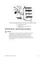
PHP I/O Carrier: Removing and Installing ....................................................................... 137
Removing the PHP I/O Carrier................................................................................. 138
Installing the PHP I/O Carrier................................................................................... 138
vi
Contents
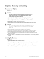
Midplane: Removing and Installing .................................................................................. 140
Removing the Midplane ........................................................................................... 140
Installing the Midplane ............................................................................................. 140
Memory Modules and DIMMs: Removing and Installing .................................................. 142
Removing a Memory Module ................................................................................... 142
Installing a Memory Module ..................................................................................... 142
Removing DIMMs .................................................................................................... 144
Installing DIMMs ...................................................................................................... 145
Processors: Removing and Installing............................................................................... 147
Removing a Processor ............................................................................................ 148
Installing a Processor .............................................................................................. 149
Front Side Bus (FSB) Termination Board Assembly ......................................................... 150
Removing a Termination Board ............................................................................... 150
Installing a Termination Board ................................................................................. 151
Replacing the Backup Battery .......................................................................................... 152
7 Solving Problems
Resetting the System ....................................................................................................... 155
Initial System Startup ....................................................................................................... 155
Checklist .................................................................................................................. 155
Running New Application Software................................................................................... 156
Checklist .................................................................................................................. 156
After the System Has Been Running Correctly ................................................................. 156
Checklist .................................................................................................................. 156
More Problem-Solving Procedures................................................................................... 157
Preparing the System for Diagnostic Testing ........................................................... 157
Using PCDiagnostics ............................................................................................... 157
Monitoring POST ..................................................................................................... 158
Verifying Proper Operation of Key System Lights .................................................... 158
Confirming Loading of the Operating System .......................................................... 158
Specific Problems and Corrective Actions ........................................................................ 158
Power Light Does Not Light ..................................................................................... 159
No Beep Codes ....................................................................................................... 159
No Characters Appear on Screen ............................................................................ 159
Characters Are Distorted or Incorrect ...................................................................... 160
System Cooling Fans Do Not Rotate Properly ......................................................... 160
Diskette Drive Activity Light Does Not Light ............................................................. 160
Hard Disk Drive Activity Light Does Not Light .......................................................... 161
CD-ROM Drive Activity Light Does Not Light ........................................................... 161
Network Problems ................................................................................................... 161
PCI Installation Tips................................................................................................. 161
Problems with Application Software.................................................................................. 162
Bootable CD-ROM Is Not Detected .................................................................................. 162
Error and Informational Messages.................................................................................... 162
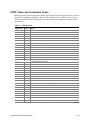
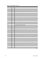
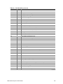
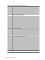
POST Codes and Countdown Codes....................................................................... 163
POST Error Codes and Messages ................................................................................... 167
SRPL8 Server System Product Guide
vii
8 Technical Reference
Connectors....................................................................................................................... 172
Diskette Drive .......................................................................................................... 174
IRMC Connector ...................................................................................................... 175
VGA Video Port ....................................................................................................... 176
Keyboard and Mouse............................................................................................... 176
Parallel Port ............................................................................................................. 177
Serial Ports A and B ................................................................................................ 177
Universal Serial Bus (USB) ...................................................................................... 178
SCSI ........................................................................................................................ 178
IDE .......................................................................................................................... 179
PCI .......................................................................................................................... 180
Configuration Switches..................................................................................................... 182
General Procedure to Change Switch Settings ........................................................ 183
CMOS Clear Switch................................................................................................. 183
Password Clear Switch ............................................................................................ 184
Recovery Boot Switch.............................................................................................. 184
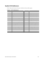
System I/O Addresses...................................................................................................... 185
Memory Map .................................................................................................................... 186
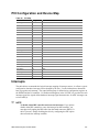
PCI Configuration and Device Map .................................................................................. 187
Interrupts .......................................................................................................................... 187
Video Modes .................................................................................................................... 189
A Power System: Description/Calculating Power Usage
Power System .................................................................................................................. 191
Power Supply Input Voltages................................................................................... 192
Power Supply Output Voltages ................................................................................ 192
Server Current Usage ...................................................................................................... 193
Calculating Power Usage ................................................................................................. 194
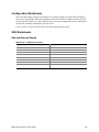
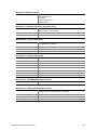
B Equipment Log and Configuration Worksheets
Equipment Log ................................................................................................................. 197
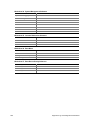
Configuration Worksheets........................................................................................ 199
SSU Worksheets ..................................................................................................... 199
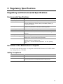
C Regulatory Specifications
Regulatory and Environmental Specifications................................................................... 207
Environmental Specifications ................................................................................... 207
Declaration of the Manufacturer or Importer ............................................................ 207
Safety Compliance................................................................................................... 207
Electromagnetic Compatibility (EMC) ...................................................................... 208
viii
Contents
D Warnings
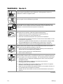
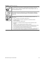
WARNING: English (US) ................................................................................................. 210
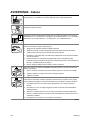
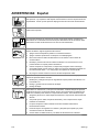
AVERTISSEMENT: Français........................................................................................... 212
WARNUNG: Deutsch ...................................................................................................... 214
AVVERTENZA: Italiano ................................................................................................... 216
ADVERTENCIAS: Español.............................................................................................. 218
Index .................................................................................................................................... 221
SRPL8 Server System Product Guide
ix
x
Contents
Part I: User’s Guide
1 Chassis Description
2 Boardset Description
3 Configuration Software and Utilities
4 Hot-Swapping Fans, SCSI Hard Drives, and Power Supplies
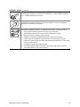
WARNING
Only a QUALIFIED SERVICE TECHNICIAN is authorized to remove
the server covers and to access any of the components inside the server.
Before removing the covers, see “Safety: Before You Remove Server
Covers” on page 93 and “ Warnings and Cautions” on page 94.
This manual is divided into two parts:
• User’s Guide, beginning on page 11—describes procedures that DO NOT REQUIRE internal
server access. You do not need to be a qualified service technician to perform procedures
listed in the User’s Guide.
• Service Technician’s Guide, beginning on page 91—describes procedures that REQUIRE
internal server access. You must be a qualified service technician to perform procedures listed
in the Service Technician’s Guide.
✏
NOTE
The SRPL8 server system is an upgrade to the SRPM8 server system with
PCI-X features added. The SRPL8 server system implements
PCI 2.1-compliant buses with four PCI-X-enabled slots. In this document,
the term “PCI” is loosely used to refer to PCI and PCI-X features. The term
“PCI-X” is limited to references to PCI-X only.
11
12
Part 1: User’s Guide
1 Chassis Description
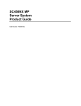
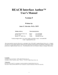
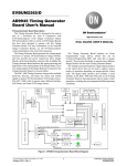
The SRPL8 rack server is easy to integrate and can easily accommodate the needs of a variety of
high-performance applications—for example, network servers, multiuser systems, and large
database operations. As your application requirements increase, you can upgrade your server with:
• More powerful and/or additional processors
• An additional processor mezzanine carrier with cache coherency filters
• An additional memory module and additional memory
• Other peripheral devices
• Add-in I/O boards
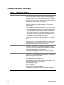
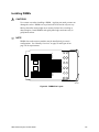
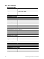
Table 1.
Server Physical Specifications
Specification
Value
Height
31.12 cm (12.25 inches, 7u)
Width
44.45 cm (17.5 inches)
Depth
71.12 cm (28.0 inches)
Weight
51.4 kg (113 lbs) minimum configuration
60 kg (132 lbs) maximum configuration
Required front clearance
10 inches (inlet airflow <35 °C / 95 °F)
Required rear clearance
8 inches (no airflow restriction)
OM08751
Figure 1. SRPL8 MP Server
13
Chassis Feature Summary
Table 2.
Chassis Feature Summary
Feature
Comment
Power system with redundancy
The 750 watt, 220 VAC autoranging power supplies include integrated
fans for cooling. When the server is configured with three supplies
(2 + 1), the third provides redundancy. The supplies can be replaced—
hot-swapped—without turning off server power. The server requires a
minimum of two power supplies. LEDs on the back of the power supply
indicate power on, failure, and predictive failure.
Server chassis
The electrogalvanized metal used in manufacturing the server chassis
minimizes electromagnetic interference (EMI) and radio frequency
interference (RFI).
The peripheral bay provides the interface for 3.5- and 5.25-inch media.
It can support:
• One 5.25-inch IDE CD-ROM drive in the 5.25-inch half-height bay.
(Optional: any IDE or single-ended SCSI device, like a tape drive.)
• Two 3.5-inch wide by 1.0- or 1.6-inch hot-swappable low-voltage
differential SCSI (LVDS) hard disk drives mounted side-by-side in
the 3.5-inch hot-swapping bays. These bays allow hot-swapping of
hard disk drives without shutting down the server.
Ten hot-plug PCI I/O expansion slots (six 33 MHz PCI, four 100 MHz
PCI-X).
The plastic front bezel provides airflow and easy access to drives in the
hot-swapping bays. The removable top covers provide proper airflow
and easy access to components inside the server. Only technically
qualified personnel should remove the server covers.
Cooling system with redundancy
Six fans (5 + 1) cool and circulate air through the server. The sixth fan
is redundant. The fans can be replaced—hot-swapped—without
turning off server power. An LED indicator mounted next to each fan
guarantees positive identification of the failed fan.
Integrated power supply fans—two or three—cool and circulate air
through the power supplies and the bottom of the chassis.
Server management
Interintegrated circuit bus (I2C) for diagnostic and intrachassis
communication. Interchassis management bus (ICMB) for interchassis
platform management communications.
Real-time clock/calendar (RTC).
Front panel controls and indicators (LEDs).
Basic Input/Output System (BIOS), Power-on Self Test (POST), and
Setup Utility stored in a flash memory device.
System Setup Utility (SSU).
QLogic† SCSI Utility.
Emergency Management Port (EMP) utility.
Field Replacement Unit (FRU) and Sensor Data Record (SDR) load
utility.
14
Chassis Description
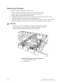
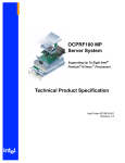
Chassis Front Controls and Indicators
A
B
C
D E F G
H
Q
P
O N
M L
KJ I
OM07301
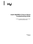
Figure 2. Front Controls and Indicators
SRPL8 Server System Product Guide
15
Table 3.
Item
Front Controls and Indicators
Feature
Description
Front Panel
A
Power switch
When pressed, it turns on or off the server. The +5 V standby voltage
is ON whenever the server is plugged in.
B
Reset switch
When pressed, it resets the server and causes the power-on self test
(POST) to run.
C
NMI switch
When pressed, it causes a nonmaskable interrupt. This switch is
recessed behind the front panel to prevent inadvertent activation. It
must be pressed with a narrow tool (not supplied).
D
Power LED (green)
When lit continuously, it indicates the presence of DC power in the
server. When not lit, it indicates power is turned off or power source is
disrupted.
E
Power fault LED (yellow)
When lit continuously, it indicates presence of DC power.
F
Cooling fault LED (yellow)
When flashing, it indicates a fan failure.
G
Drive fault LED (yellow)
When lit continuously, it indicates an asserted fault status on one or
more hard disk drives in the hot-swapping bay. When flashing, it
indicates drive reset in progress.
H
Front panel LCD
Displays information about processor type and failure codes.
Status LEDs for SCSI Drives in Hot-swapping Bays
I
Drive power LED (green)
When lit continuously, it indicates the presence of the drive and power
on the drive.
J
Drive activity LED (green)
Indicates drive activity.
K
Drive fault LED (yellow)
When lit continuously, it indicates an asserted fault status on one or
more hard disk drives in the hot-swapping bay. When flashing, it
indicates drive reset in progress.
Typical CD-ROM Drive
L
Open/close button
When pressed, it opens or closes the CD-ROM tray.
M
Activity LED
When lit, it indicates the drive is in use.
N
Volume control
It adjusts the volume of headphones or speakers.
O
Headphone jack
It provides a connection for headphones or speakers.
3.5-inch Diskette (Floppy) Drive
16
P
Activity LED
When lit, it indicates the drive is in use.
Q
Ejector button
When pressed, it ejects the diskette.
Chassis Description
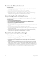
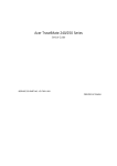
Chassis Back Controls and Features
B CD
A
E
F
G
H
I
N
M
J
L
K
OM08781
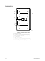
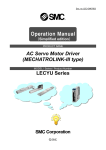
Figure 3. Chassis Back View
A.
B.
C.
D.
E.
F.
G.
H.
I.
J.
PCI add-in board expansion slots
External LVDS connector
PS/2†-compatible keyboard/mouse port, 6-pin
PS/2-compatible keyboard/mouse port, 6-pin
PS/2-compatible serial ports A and B, 9-pin RS-232 connector
Super VGA compatible, 15-pin video connector
PS/2-compatible parallel port (LPT), 25-pin bidirectional subminiature D connector
USB ports 0 and 1, 4-pin connector
Interchassis Management Bus (ICMB) connectors port 1 and 2
Power supplies (in this view, supplies must be populated from left to right; the right
bay would contain the redundant supply)
K. Power supply failure LED (yellow)
L. Power supply predictive failure LED (yellow) for power supply fan
M. Power supply power LED (green)
N. AC input power connector
SRPL8 Server System Product Guide
17
Peripherals
The peripheral bay provides the interface for 3.5-inch and 5.25-inch media.
3.5-inch Diskette Drive
The 3.5-inch diskette drive in the peripheral bay supports 720 KB and 1.44 MB media. The drive
is externally accessible from the front of the system.
3.5-inch Hard Drive Bays
The peripheral bay contains two hot-swapping bays for two 3.5-inch wide (1.0-inch high or
1.6-inch high) wide/fast-20 SCSI III SCA-type hard drives. The hard drives are externally
accessible at the front of the system and connect to a wide LVDS hot-swap SCSI backplane.
As part of the hot-swap implementation, a drive carrier with an integral heatsink is required. The
drives are mounted in the carrier with four fasteners and the carrier snaps into the chassis with a
locking handle. A single metal EMI shield and plastic door cover the drive bays. A hot-swapping
bay is provided for drives that are 3.5 inches wide and 1.0 or 1.6 inches high. Drives can consume
up to 24 watts of power and must be specified to run at a maximum ambient temperature of
40 °C (104 °F).
5.25-inch Removable Media Device Bay
The peripheral bay has one 5.25-inch half-height bay that is accessible from the front of the
system. This bay is intended to provide space for a tape drive for backup or for another removable
device.
We recommend that you do not use this bay for a hard disk drive, because hard disk drives
generate EMI (increasing ESD susceptibility), and because of inadequate cooling.
18
Chassis Description
Hot-Swap Power Supplies
The chassis can be configured with two or three 750-watt power supplies in a 2 + 1 redundancy
configuration. If you have three supplies installed, you can hot-swap a failed supply without
affecting system functionality. If you have two supplies installed, they must occupy the left and
center bays (as you face the back of the server—see Figure 3 on page 17). Each supply is designed
to minimize EMI and RFI. This system is designed to operate at 100/200 VAC only.
The DC output voltages of each power supply are:
• +3.3 V at 36.0 A max
• +5 V at 36.0 A max (total combined output of +3.3 V and +5.5 V not to exceed 195 W)
• +12 V at 36.0 A with 42.0 A <10ms peak
• +24 V at 100 mA
• -12 V at 1.0 A
• +5 V standby 1.0 A
Each supply docks to a 36-pin connector on the system midplane.
System Cooling
The server contains two independent cooling subsystems:
• The upper system, cooling the front panel, profusion carrier, and I/O carrier
(5 + 1 redundancy)
• The lower system, cooling the memory modules, peripheral bay, and power supplies
(2 + 1 redundancy)
Both subsystems offer redundant cooling capabilities. As shipped from the factory, the minimum
configuration includes six system fans in the upper subsystem and two power supplies (each has an
integrated fan). You can install one additional power supply.
✏
NOTE
All chassis covers must be on the system for proper cooling.
SRPL8 Server System Product Guide
19
20
Chassis Description
2 Boardset Description
The modular scaleable architecture of the SRPL8 rack server supports symmetrical
multiprocessing (SMP) and a variety of operating systems. The server comes with Peripheral
Component Interconnect (PCI) and Industry Standard Architecture (ISA) buses. ISA buses are
used internally only. The system has no ISA slots or a way for the user to make use of the ISA
bus. The server boardset consists of a set of printed circuit boards:
• Profusion carrier
Processor mezzanine board(s)
Front side bus (FSB) terminator modules
•
•
•
•
Cache coherency filters
PCI hot-plug (PHP) I/O carrier
Low-voltage differential SCSI (LVDS) hot-swap disk backplane
I/O riser board
Two memory modules
Front panel controller board
Midplane
The profusion carrier is mounted horizontally toward the front of the chassis, and the PHP I/O
carrier is mounted horizontally towards the rear of the chassis. The carriers plug into connectors
on the midplane mounted between the two carriers. The midplane interconnects the carriers with
the memory modules and power supplies. The front panel board is mounted in front of the
profusion carrier in the same plane. This board provides the user interface, server management,
cooling system control, and power control.
21
D
C
B
A
E
C
F
OM07505
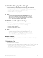
Figure 4. Boardset Overview
A. Front panel board
B. Profusion carrier
C. Processor mezzanine board
D. I/O carrier
E. Midplane
F. Memory modules
Boardset Features
Table 4.
Boardset Features
Feature
Description
Profusion carrier
The profusion carrier provides the interface for processors (via one or two processor
mezzanine boards), memory modules, and cache coherency filters.
The profusion carrier supports up to two processor mezzanine boards. Each
mezzanine board supports up to four Pentum® III Xeon™ processors.
Installed: Up to eight Pentium III Xeon processors, packaged in single edge contact
(S.E.C.) cartridges and installed in 330-pin Slot 2 processor connectors, operating at
5/12 V. The profusion carrier provides connectors for two processor mezzanine
boards. Each mezzanine board provides four Slot 2 connectors. The carrier's voltage
regulator is automatically programmed by the processor's VID pins to provide the
required voltage.
Processor
mezzanine boards
Pentium III Xeon
processor
packaged in an
S.E.C. cartridge
continued
22
Boardset Description
Table 4.
Boardset Features (continued)
Feature
Description
Memory modules
Two dual plug-in modules containing interleaved pathway to main memory supporting
PC100 registererd SDRAM. Each memory module supports from 128 MB to 16 GB of
error correction code (ECC) memory using sixteen 72-bit dual inline memory modules
(DIMMs). The modules interface to the profusion carrier through the midplane.
This module plugs into any unpopulated Slot 2 connector on either processor
mezzanine board. The module terminates the FSB GTL+ signals of the
Slot 2 connector when a processor S.E.C. cartridge is not installed in a connector.
The cache coherency filters contain information on each of the two processor buses,
thus enabling each bus to perform with minimal snoop cycles. The profusion carrier
requires that these filters be populated if the server has two processor mezzanine
boards that are both populated with processors.
Ten hot-pluggable 64-bit PCI expansion slots (six 33 MHz PCI, four 100 MHz PCI-X).
FSB terminator
module
Cache coherency
filters
PHP I/O carrier
Integrated ATI Rage XL graphics (SVGA) controller with 8 MB of video memory.
The QLogic 12160 Ultra 160 LVDS SCSI controller supports two LVDS channels.
One channel is used internally to provide support for the internal SCSI drives
(connected to the LVDS hot-swap disk backplane) and CD-ROM or tape drive. The
second LVDS channel is routed to the rear of the chassis to support external devices.
The diskette controller supports one drive.
The PCI-enhanced Integrated Drive Electronics (IDE) interface supports one IDE bus.
PS/2-compatible keyboard/mouse controller.
Two universal serial bus (USB) ports.
I/O riser board
This board contains all legacy I/O connections; it plugs into an edge connector on the
PHP I/O carrier.
PS/2-compatible keyboard and mouse ports (interchangeable).
PS/2-compatible parallel port.
Analog VGA, 15-pin video port.
Two PS/2-compatible, 9-pin serial ports.
LVDS hot-swap
disk backplane
This backplane supports hot-swapping of up to two SCA2-type SCSI drives, mounted
in carriers, in and out of the hot-swapping bays.
Front panel board
The front panel board provides the user interface to the server. The board allows
other servers to communicate with this server, even while power is down, via an
Interchassis Management Bus (ICMB).
Push-button switches control power-up, reset, and nonmaskable interrupt
(NMI) functions.
LEDs indicate power on, power supply failure, hard drive failure, or a fan or other
server cooling failure.
An LCD panel provides information about boot status, available number of
processors, and other server management information.
Midplane
The midplane:
• Electrically connects the PHP I/O and profusion carriers
• Contains the sockets for the memory modules
• Distributes DC power to the PHP I/O and profusion carrier, disk backplane, cooling
fans, memory boards, and front panel board
• Distributes the power load of the server among two or three 750-watt autoranging
power supplies
SRPL8 Server System Product Guide
23
Processor Overview
Each Pentium III Xeon processor is packaged in a single edge contact (S.E.C.) cartridge. The
cartridge includes:
• The processor core with an integrated 32 KB primary (L1) cache
• The secondary (L2) cache
• A thermal plate
• A back cover
Processors used with the SRPL8 server must be:
•
•
•
•
5/12 volts
100 MHz FSB
1 or 2 MB cache
Validated by Intel for SRPL8 systems
Each processor implements the MMX™ technology with streaming SMID extensions and
maintains full backward compatibility with the 8086, 80286, Intel386™, Intel486™, Pentium, and
Pentium Pro processors. The processor’s numeric coprocessor significantly increases the speed of
floating-point operations and complies with ANSI/IEEE standard 754-1985.
Each S.E.C. cartridge connects to one of two processor mezzanine boards through a 330-pin
Slot 2 edge connector (SC330.1). The cartridge is secured to the mezzanine carrier by a retention
bracket. Each mezzanine board connects to the profusion carrier. Depending on configuration,
your system has one to eight processors.
The processor external interface is multiprocessor (MP)-ready and operates at 100 MHz. The
processor contains a local APIC unit for interrupt handling in MP and uniprocessor
(UP) environments.
The L2 cache is located on the same die as the processor core and L1 cache. The cache:
• Is offered in 1 MB and 2 MB configurations
• Is ECC protected
• Operates at the full core clock rate
24
Boardset Description
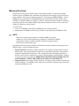
Memory Overview
Main memory resides on two add-in boards, called memory modules. Each memory module
contains slots for 16 DIMMs and is attached to the profusion carrier through a 300-pin connector
on the midplane. The memory controller supports PC 100-registered SDRAM DIMMs. Various
DIMM sizes are supported, but each DIMM must be at least 128 MB. Memory amounts from
128 MB to 16 GB per module are supported. The ECC used for the memory module is capable of
correcting single-bit errors (SBEs) and detecting 100% of double-bit errors over one code word.
Nibble error detection is also provided.
You can install:
• From 1 to 32 DIMMs (total number of DIMMs for two memory modules)
• Equal number of DIMMs on each memory module (except when only one DIMM is used)
✏
NOTE
When only a single memory module is installed, DIMM sizes on that
module may vary, but when both memory modules are installed, the DIMM
configuration on the two modules should be identical to support memory
interleaving for performance gains.
Depending on how the memory modules are installed, the memory subsystem can operate in two
different modes: interleaved and single-port.
• Interleaved mode (two memory modules installed): The memory modules share a common
address range. One memory module responds to even-numbered cache lines, while the other
responds to odd-numbered cache lines. This configuration offers the highest performance
because it allows the two modules to be used in a balanced fashion, reducing address conflicts.
To operate in interleaved mode, the DIMMs MUST BE INSTALLED IN PAIRS (ONE ON
EACH MODULE) AND IN THE SAME LOCATIONS ON EACH MODULE.
• Single port mode (one memory module installed): The single memory module responds to all
memory addresses. The DIMMs on this single carrier need not be installed in pairs and can be
installed one DIMM at a time.
SRPL8 Server System Product Guide
25
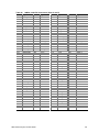
DIMM Installation Sequence
A single carrier will support DIMM population in various configurations (empty sockets included).
However, when fewer than 16 DIMMs are installed on a memory module, the preferred population
order is to start from the lowest J number and populate sequentially to the highest. This
recommendation helps maintain optimal signal integrity and thermal performance.
✏
NOTE
Maximum capacity is limited to 16 GB with one memory module installed.
This increases to 32 GB with two modules.
Some OSs and application programs use base memory while others use both conventional and
extended memory. Examples:
• Base memory: MS-DOS†, OS/2, Windows NT†, and UNIX†
• Conventional and extended memory: OS/2, Windows NT, and UNIX
MS-DOS does not use extended memory; however, some MS-DOS utility programs like RAM
disks, disk caches, print spoolers, and windowing environments use extended memory for better
performance.
BIOS automatically detects, sizes, and initializes the memory array, depending on the type, size,
and speed of the installed DIMMs, and reports memory size and allocation to the system via
configuration registers.
✏
NOTE
DIMM sizes and compatibility: Use DIMMs that have been tested for
compatibility. Contact your sales representative or dealer for a list of
approved DIMMs.
26
Boardset Description
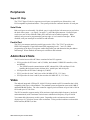
Peripherals
Super I/O Chip
The 37C937 Super I/O device supports two serial ports, one parallel port, diskette drive, and
PS/2-compatible keyboard and mouse. The system provides the connector interface for each port.
Serial Ports
Both serial ports are relocatable. By default, port A is physically the left connector (as you look at
the back of the system — see Figure 3 on page 17), port B the right connector. Each serial port
can be set to one of four different COMx ports, and each can be enabled separately. When
enabled, each port can be programmed to generate edge- or level-sensitive interrupts. When
disabled, serial port interrupts are available to add-in boards.
Parallel Port
The 25/15-pin connector stacks the parallel port over the VGA. The 37C937 provides one
IEEE 1284-compatible 25-pin bidirectional EPP (supporting levels 1.7 and 1.9). BIOS
programming of the Super I/O registers enables the parallel port and determines the port address
and interrupt. When disabled, the interrupt is available to add-in boards.
Add-In Board Slots
The I/O carrier has ten 64-bit PCI buses contained in four PCI segments:
• PCI-A provides for PCI slots 1 and 2 (33 MHz), dual-channel LVDS SCSI controller, video,
and PIIX4E.
The PIIX4E controls communications to IDE, onboard ISA, USB, and Super I/O for
handling the keyboard, mouse, diskette drive, parallel port, and serial ports.
• PCI-B provides for PCI slots 3 through 6 (33 MHz).
• PCI-C provides for slots 7 and 8 (two of the 100 MHz PCI-X, 3.3 V slots).
• PCI-D provides for slots 9 and 10 (the two other 100 MHz PCI-X, 3.3 V slots).
Video
The onboard, integrated ATI Rage XL 64-bit VGA chip contains an SVGA controller that is fully
compatible with legacy video standards. The standard system configuration comes with 8 MB of
onboard SDRAM memory. The video controller supports pixel resolutions of up to 1600 x 1200 at
85 Hz and up to 16.7 M colors.
The SVGA controller supports analog VGA monitors (single and multiple frequency, interlaced
and noninterlaced) with a maximum vertical retrace noninterlaced frequency of up to 100 Hz.
You cannot add video memory to this system. Depending on the environment, the controller
displays up to 16.7 M colors in some video resolutions. It also provides hardware-accelerated bit
block transfers (BITBLT) of data.
SRPL8 Server System Product Guide
27
SCSI Controller
A QLogic 12160 Ultra 160 SCSI chip provides two 16-bit high-speed SCSI channels. This
high-performance SCSI controller is capable of providing data rates up to 160 MB/sec per channel
in 16-bit operations to ensure maximum data throughput while minimizing PCI bus overhead.
Each channel is capable of operations using either 8- or 16-bit SCSI providing 10 MB/sec
(Fast-10) or 20 MB/sec (Fast-20) throughput, or 20 MB/sec (Ultra), 40 MB/sec (Ultra-wide),
80 MB/sec (40 MHz) (Ultra-2), or 160 MB/sec (40 MHz double clocked) (Ultra 160).
The QLA12160 has its own set of PCI configuration registers and SCSI I/O registers. As a
PCI 2.1 bus master, the controller supports burst data transfers on PCI up to the maximum rate of
132 MB/sec using on-chip buffers.
In the hot-swap SCSI hard drive bay, the system supports up to two 1-inch SCSI hard disk drives.
The 5.25-inch removable media bay supports one SCSI or IDE device (the controller itself
supports more devices, but the 5.25-inch bay can contain a maximum of one device). SCSI
devices do not need to operate at the ultra transfer rate. All drives on the bus must be Ultra 160
(LVD) to run at 160 MB/sec. The 5, 10, and 20 MHz operations can coexist on the bus, and each
device will interact at its appropriate speed.
No logic, termination, or resistor loads are required to connect devices to the SCSI controller other
than termination in the device at the end of the cable. The SCSI bus is terminated on the
I/O carrier with active terminators.
IDE Controller
IDE is a 16-bit interface for intelligent disk drives with AT† disk controller electronics onboard.
The PCI/ISA/IDE Accelerator, called PIIX4E, is a multifunction device on the I/O carrier that acts
as a PCI-based Fast IDE controller. The device controls:
• PIO and IDE DMA/bus master operations
• Mode 4 timings
• Transfer rates up to 22 MB/sec (33 MB/sec using ultra DMA transfers)
• Buffering for PCI/IDE burst transfers
• Master/slave IDE mode
Keyboard and Mouse
The PS/2 compatible keyboard and mouse connectors are mounted in a single-stacked housing
with the mouse connector over the keyboard. External to the system, they appear as two
connectors.
The user can plug in the keyboard and mouse to either connector before powering up the system.
BIOS detects these and configures the keyboard controller accordingly.
The keyboard controller is functionally compatible with the 8042A microcontroller. The system
can be locked automatically if no keyboard or mouse activity occurs for a predefined length of
time, if specified through the SSU (see security options in “Security Add-In” on page 57). Once
the inactivity (lockout) timer has expired, the keyboard and mouse do not respond until the
previously stored password is entered.
28
Boardset Description
Server Management
Most of the server management features are implemented using three microcontrollers, the
baseboard management controller (BMC) on the I/O carrier, the front panel controller (FPC) on the
front panel board, and the hot-swap controller (HSC) on the LVDS backplane.
The primary function of the BMC is to autonomously monitor system platform management events
and log their occurrence in the nonvolatile System Event Log (SEL). While monitoring, the BMC
maintains the nonvolatile sensor data record repository (SDRR), from which run-time information
can be retrieved. The BMC provides an ISA host interface to SDRR information, so software
running on the server can poll and retrieve the current status of the platform. A shared register
interface is defined for this purpose.
SEL contents can be retrieved after system failure or during regularly scheduled maintenance. To
retrieve SEL contents, field service personnel use tools such as the SSU SEL Viewer or the
Intel® Server Control management software.
The BMC:
• Provides temperature and voltage monitoring
• Monitors processor presence and performs Fault Resilient Booting (FRB) control
• Manages SEL interface
• Manages SDRR interface
• Manages SDR/SEL timestamp clock
• Provides Field Replaceable Unit (FRU) information interface
• Provides system management watchdog timer functions
• Provides pre-timeout (of watchdog timer) SMI capability
• Provides front panel NMI handling
• Provides event receiver functionality
• Manages ISA host and Intelligent Platform Management Bus (IPMB) interface
• Manages secure mode control, front panel lock/unlock initiation, and video blank and diskette
write protect monitoring and control
• Provides sensor event initialization agent
• ACPI Support
SRPL8 Server System Product Guide
29
Front Panel Controller (FPC)
The FPC manages:
• Server power control consolidation from several sources
•
•
•
•
•
•
•
•
•
•
•
•
push-button power signal from the front panel connector
real-time clock (RTC)
Intel® remote management card (IRMC), if installed
commands from the Intelligent Platform Management Bus
Power and reset switch interfaces
Fault LEDs
Chassis, midplane and power supplies Field Replacement Unit (FRU) inventory interface
Server hard reset generation
Server power fault indication
Interchassis Management Bus (ICMB) bridge device
EMP connection
LCD interface
Fan predictive failure detection and indicator control
Power supply predictive failure detection and indicator control
ACPI Support
Wake on LAN† via Magic Packet† support
Hot-swap Controller (HSC)
The HSC:
• Implements the SAF-TE command set
• Controls the fault lights and drive power-on
• Provides a path for management information via SCSI
• Retrieves drive fault status, backplane temperature, and fan failure information via the IPMB
• Queries the status of the front panel controller for power supply information
• Controls drive power-on and power-down, facilitating hot-swapping
30
Boardset Description
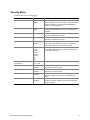
System Security
There are several ways to prevent unauthorized entry or use of the server.
Security with BIOS Setup:
•
•
•
Set server administrative and user passwords.
Set secure mode to prevent keyboard or mouse input and to prevent use of the front panel
controls.
For more information, see “Security Menu” on page 45.
Security with the System Setup Utility (SSU):
•
•
•
•
•
•
Enable the keyboard lockout timer so that the server requires a password to reactivate the
keyboard and mouse after a specified time-out period of 1 to 128 minutes.
Set an administrative password.
Set a user password.
Activate the secure mode hot-key.
Disable writing to the diskette drive.
For more information, see “Security Add In” on page 57.
Password Protection
BIOS passwords prevent unauthorized tampering with the server. If you set the user password, but
not the administrative password, BIOS requires you to enter the user password before you can boot
the server or run the SSU. If you set both passwords, entering either password lets you boot the
server or enable the keyboard and mouse. Only the administrative password lets you change the
server configuration with the flash-resident Setup utility.
Secure Boot Mode
Secure boot mode allows the server to boot and run the OS. However, you cannot use the
keyboard or the mouse until you enter the user password.
You can use Setup to put the server in secure boot mode. If BIOS detects a disk in the CD-ROM
drive or a diskette in floppy drive A at boot time, it prompts you for a password. When you enter
the password, the server boots from the disk in the CD-ROM drive or the diskette in drive A.
Entering a password also disables secure mode.
If there is no disk in the CD-ROM drive or diskette in drive A, the server boots from drive C and
automatically goes into secure mode. All enabled secure mode features go into effect at boot time.
If you set a hot-key combination, you can secure the server immediately.
Boot Sequence Control
The BIOS security features determine the boot devices and the boot sequence. They also control
disabling writes to the diskette drive in secure mode. You can use the SSU or Setup to select each
boot device. The default boot sequence is diskette, hard disk, CD-ROM, and network.
SRPL8 Server System Product Guide
31
Boot Without Keyboard
The server can boot with or without a keyboard. Before it boots, BIOS displays a message
keyboard detection. During POST, BIOS automatically detects and tests the keyboard if one is
present.
Locked Power and Reset Switches
The power and reset push-button switches on the front panel are locked when the server is in
secure mode. To exit from the secure mode, you must enter your user password.
Diskette Write Protect
If Diskette Write Protect is enabled in Setup, it write-protects the diskette drive only while the
server is in the secure mode. To exit secure mode, enter your user password.
Video Blanking
If Video Blanking is enabled in Setup, the video display will be off when the server is in secure
mode. To exit secure mode, enter your user password.
Emergency Management Port (EMP)
The EMP is a feature of server management. EMP lets the front panel controller (FPC)
communicate with the server via the serial port even if the server power is off. To restrict
EMP access, you can enable an administrator password in Setup. If the administrator enters a new
EMP password or clears an old one, BIOS sends the appropriate command via the I2C bus
interface to the FPC. To change the password from Setup again, enter the new password twice.
If the administrator sets the Password Clear switch to the Clear position, BIOS clears the
administrator and user passwords (to change switches, see “Configuration Switches” on page 182).
It also attempts to clear the EMP password. If the FPC is not present or is not functioning
properly, BIOS times out and continues.
32
Boardset Description
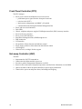
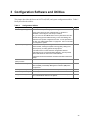
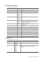
3 Configuration Software and Utilities
This chapter describes the Power-on Self Test (POST) and system configuration utilities. Table 5
briefly describes the utilities.
Table 5.
Configuration Utilities
Utility
BIOS Setup (“Setup”)
Description and brief procedure
Page
You can use Setup to change system configuration defaults.
35
If the system does not have a diskette drive, or the drive is
disabled or misconfigured, use Setup to enable it.
Or, you can move the CMOS switch on the system board from the
default setting (Protect CMOS memory) to the Clear setting; this
will allow most system configurations to boot. For the procedure to
do this, see “CMOS Clear Switch” on page 183. Then run the SSU
to configure the system.
System Setup Utility (SSU)
Use for extended system configuration of onboard resources and
add-in boards, viewing the system event log (SEL), setting boot
device priority, or setting system security options.
51
The SSU can be run from either the configuration software
CD-ROM or from a set DOS-bootable diskettes. See the printed
Quick Start Guide to make a set of SSU diskettes.
Information entered via the SSU overrides information entered via
Setup.
Direct Platform Control
(DPC) Console
Use to access and monitor the server remotely.
63
FRUSDR Load Utility
Use to update the Field Replacement Unit (FRU), Sensor Data
Record (SDR), and Desktop Management Interface (DMI) flash
components.
72
BIOS Update Utility
Use to update BIOS or recover from a corrupted BIOS update.
77
Firmware Update Utility
Use to update the BMC flash PROM.
80
QLogic SCSI Utility
Use to configure or view the settings of the SCSI host adapters
and onboard SCSI devices in the system.
80
33
Hot Keys
Use the keyboard’s numeric pad to enter numbers and symbols.
Table 6.
Hot Keys
To do this:
Press these keys
Clear memory and reload the operating
systemthis is a system reset.
<Ctrl+Alt+Del>
Secure your system immediately.
<Ctrl+Alt> + hotkey (Set your hot-key combination with the SSU
or Setup.)
Enter BIOS Setup during BIOS POST.
F2
Abort memory test during BIOS POST.
ESC (Press while BIOS is updating memory size on screen.)
Power-on Self Test (POST)
Each time you turn on the system, POST starts running. POST checks the carriers, processors,
memory, keyboard, and most installed peripheral devices. During the memory test, POST displays
the amount of memory it is able to access and test. The length of time needed to test memory
depends on the amount of memory installed. POST is stored in flash memory.
1. Turn on your video monitor and system. After a few seconds, POST begins to run.
2. After the memory test, these screen prompts and messages appear:
Keyboard Detected
Mouse Initialized
Press <F2> to enter Setup
3. If you do not press <F2> and do NOT have a device with an OS loaded, the above message
remains for a few seconds while the boot process continues, and the system beeps once. Then
this message appears:
Operating System not found
(To create software installation diskettes, see the printed Quick Start Guide.)
If you do not press <F2>, the boot process continues and this message appears:
Press <Ctrl> <C> to enter SCSI Utility
4. Press <Ctrl+C> if SCSI devices are installed. When the utility opens, follow the displayed
instructions to configure the onboard SCSI host adapter settings and to run the SCSI utilities.
Also see “Using the QLogic SCSI Utility” on page 80. If you do not enter the SCSI utility, the
boot process continues.
5. Press <Esc> during POST to access a boot menu when POST finishes. From this menu, you
can choose the boot device or enter BIOS Setup.
After POST completes, the system beeps once.
What appears next on the screen depends on if you have an OS loaded on the server (or which OS).
If the system halts before POST completes running, it emits a beep code indicating a critical
system error that requires immediate attention. If POST can display a message on the video
display screen, the speaker beeps twice as the message appears.
34
Configuration Software and Utilities
Note the screen display and write down the beep code you hear; this information is useful for your
service representative. For a listing of beep codes and error messages that POST can generate, see
Chapter 7, “Solving Problems,” beginning on page 155.
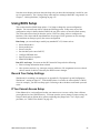
Using BIOS Setup
This section describes BIOS Setup options. Use Setup to change the system configuration
defaults. You can run Setup with or without an OS being present. Setup stores most of the
configuration values in battery-backed CMOS; the rest of the values are stored in flash memory.
The values take effect when you boot the system. POST uses these values to configure the
hardware; if the values and the actual hardware do not agree, POST generates an error message.
You must then run Setup to specify the correct configuration.
Run Setup: you can run Setup to modify any standard PC AT† feature such as:
•
•
•
•
•
•
•
Select diskette drive
Select parallel port
Select serial port
Set time/date (to be stored in RTC)
Configure IDE hard drive
Specify boot device sequence
Enable SCSI BIOS
Run SSU, not Setup: You must run the SSU instead of Setup to do the following:
•
•
Enter or change information about a board
Alter system resources (e.g., interrupts, memory addresses, I/O assignments) to user-selected
choices instead of choices selected by the BIOS resource manager
Record Your Setup Settings
Worksheets for recording your settings are in Appendix B, “Equipment Log and Configuration
Worksheets”, starting on page 197. If the default values ever need to be restored (after a CMOS
clear, for example), you must run Setup again. Referring to the worksheets could make your task
easier.
If You Cannot Access Setup
If the diskette drive is misconfigured so that you cannot access it to run a utility from a diskette,
you might need to clear CMOS memory. You must open the system, change a jumper setting, use
Setup to check and set diskette drive options, and change the jumper back. For a step-by-step
procedure, see "CMOS Clear Switch" on page 183.
SRPL8 Server System Product Guide
35
Starting Setup
You can enter and start Setup under several conditions:
• When you turn on the system, after POST completes the memory test.
• When you reboot the system by pressing <Ctrl+Alt+Del> while at the DOS operating system
prompt.
• When you have moved the CMOS switch to the “Clear CMOS” position (enabled); for a
step-by-step procedure, see “CMOS Clear Switch” on page 183.
In the three conditions listed above, after rebooting, you will see this prompt:
Press <F2> to enter SETUP
In a fourth condition, when CMOS/NVRAM has been corrupted, you will see other prompts but
not the <F2> prompt:
Warning:
cmos checksum invalid
Warning:
cmos time and date not set
In this condition, BIOS will load default values for CMOS and attempt to boot.
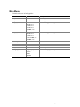
Setup Menus
Setup has six major menus and several submenus:
1. Main Menu
• IDE submenu
• Keyboard Features submenu
2. Advanced Menu
• PCI Configuration submenu
PCI Mode submenu
• I/O Device Configuration submenu
• Advanced Chipset Control submenu
3. Security Menu
4. Server Menu
• System Management submenu
• Console Redirection submenu
5. Boot Menu
• Boot Device Priority submenu
• Hard Drive submenu
6. Exit Menu
36
When you see this:
What it means:
On screen, an option is shown but you
cannot select it or move to that field.
You cannot change or configure the option in that menu screen.
Either the option is autoconfigured or autodetected, or you must
use a different Setup screen, or you must use the SSU.
On screen, the phrase Press Enter
appears next to the option.
Press <Enter> to display a submenu that is either a separate
full-screen menu or a pop-up menu with one or more choices.
Configuration Software and Utilities
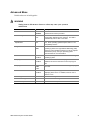
The rest of this section lists the features that display onscreen after you press <F2> to enter Setup.
Not all of the option choices are described, because (1) a few are not user-selectable but are
displayed for your information, and (2) many of the choices are relatively self-explanatory.
Press
To
F1
Get help about an item.
ESC
Go back to a previous item.
↑
Select the previous value in a menu option list.
↓
Select the next value in a menu option list.
←→
Select a major menu.
-
Change the value of the current menu item to the previous value.
+
Change the value of the current menu item to the next value.
Enter
Activate submenus, select feature options, and change feature values.
F9
Display the following message:
Setup Confirmation
Load default configuration now?
[Yes]
[No]
The [Yes] button will be highlighted. If you press <Enter>, all Setup fields return to their
default values. If you press <ESC> or select No, the server returns to the configuration it
had before you pressed <F9>, without affecting any existing field values.
F10
Display the following message:
Setup Confirmation
Save configuration changes and exit now?
[Yes]
[No]
The [Yes] button will be highlighted. If you press <Enter>, all current Setup values are
saved, and the system is reset. If you press <ESC> or select No, the server returns to
the configuration it had before you pressed <F10>, without affecting any existing values.
SRPL8 Server System Product Guide
37
Main Menu
Default values are in bold typeface.
Feature
Option
Description
System Time
HH:MM:SS
Sets the System Time.
System Date
MM/DD/YYYY
Sets the System Date.
Legacy Diskette A:
Disabled
360 KB, 5 ¼”
1.2 MB, 5 ¼”
720 KB, 3 ½”
1.44/1.25 MB, 3 ½”
2.88 MB, 3 ½”
Selects the floppy diskette type for drive A.
Legacy Diskette B:
Disabled
360 KB, 5 ¼”
1.2 MB, 5 ¼”
720 KB, 5 ¼”
1.44/1.25 MB, 3 ½”
2.88 MB, 3 ½”
Selects the floppy diskette type for drive B.
Primary Master
Selects IDE submenu.
Primary Slave
Selects IDE submenu.
Processor Information
Selects Processor Information submenu.
Keyboard Features
Language
38
Selects Keyboard Features submenu.
English (US)
French
German
Italian
Spanish
Selects the language used by BIOS.
Configuration Software and Utilities
IDE Submenu
Default values are in bold typeface.
Feature
Option
Description
Type
None
CD-ROM
IDE Removable
ATAPI Removable
User
Auto
If "Auto" is selected, BIOS determines the parameters
during POST.
If "User" is selected, BIOS Setup prompts the user to fill in
the drive parameters. Drive types 1 through 39 are
predetermined drive types.
Cylinders
Displays the number of cylinders.
Heads
Displays the number of read/write heads.
Sectors
Displays the number of sectors per track.
Maximum Capacity
Displays the capacity of the drive.
Multisector Transfers
Disabled
2 sectors
4 sectors
8 sectors
16 sectors
Displays status of multisector transfers. Autotyped by
BIOS.
LBA Mode Control
Disabled
Enabled
Displays status of Logical Block Access. Autotyped by
BIOS.
32-bit I/O
Disabled
Enabled
Enables 32-bit IDE data transfers.
Transfer Mode
Standard
Fast PIO 1
Fast PIO 2
Fast PIO 3
Fast PIO 4
Selects the method for transferring data to/from the drive.
Autotyped by BIOS.
Ultra-DMA Mode
Disabled
Mode 0
Mode 1
Mode 2
Selects the Ultra-DMA mode used for transferring data
to/from the drive. Autotyped by BIOS.
SRPL8 Server System Product Guide
39
Processor Information Submenu
Item
Description
Board 1 Processor 1 Stepping ID
Displays the processor stepping.
Board 1 Processor 1 L2 Cache Size
Displays the L2 cache size.
Board 1 Processor 2 Stepping ID
Displays the processor stepping.
Board 1 Processor 2 L2 Cache Size
Displays the L2 cache size.
Board 1 Processor 3 Stepping ID
Displays the processor stepping.
Board 1 Processor 3 L2 Cache Size
Displays the L2 cache size.
Board 1 Processor 4 Stepping ID
Displays the processor stepping.
Board 1 Processor 4 L2 Cache Size
Displays the L2 cache size.
Board 2 Processor 1 Stepping ID
Displays the processor stepping.
Board 2 Processor 1 L2 Cache Size
Displays the L2 cache size.
Board 2 Processor 2 Stepping ID
Displays the processor stepping.
Board 2 Processor 2 L2 Cache Size
Displays the L2 cache size.
Board 2 Processor 3 Stepping ID
Displays the processor stepping.
Board 2 Processor 3 L2 Cache Size
Displays the L2 cache size.
Board 2 Processor 4 Stepping ID
Displays the processor stepping.
Board 2 Processor 4 L2 Cache Size
Displays the L2 cache size.
Keyboard Features Submenu
Default values are in bold typeface.
40
Feature
Option
Description
Num Lock
Auto
On
Off
Selects power-on state for Num Lock key.
Key Click
Disabled
Enabled
Enables key click.
Keyboard auto-repeat rate
30/sec
26.7/sec
21.8/sec
18.5/sec
13.3/sec
10/sec
6/sec
2/sec
Selects key repeat rate.
Keyboard auto-repeat delay
1/4 sec
1/2 sec
3/4 sec
1 sec
Selects delay before key repeat.
Configuration Software and Utilities
Advanced Menu
Default values are in bold typeface.
WARNING
Setting items on this menu to incorrect values may cause your system to
malfunction.
Feature
Option
Description
Processor Serial Number
Disabled
Enabled
Enables or disables the Processor Serial Number feature
of the Pentium III Xeon processor.
Reset Configuration Data
No
Yes
If "Yes" is selected, BIOS clears the System
Configuration Data during the next boot. The field is
automatically reset to "No" in next boot.
Use Multiprocessor
Specification
1.1
1.4
Selects the version of the Multiprocessor Specification to
use. Some operating systems require version 1.1 for
compatibility reasons.
Large Disk Access Mode
CHS
LBA
Select the drive access method for IDE drives. Most
operating systems use Logical Block Addressing (LBA).
However, some operating systems may use the Cylinder
Head Sector (CHS). See your operating system
documentation for more information.
Pause Before Boot
Disabled
Enabled
If enabled, BIOS pauses five-seconds before booting the
operating system.
Hot-plug PCI Master Control
Disabled
Enabled
Set to "Enable" to create the Hot-plug PCI Resource
Table and to reserve resources for each hot-plug PCI
slot.
Hot-plug PCI Allocation Level
Disabled:
Min.
Max.
Set amount of resources to allocate to empty hot-plug
PCI slots.
Timeout on POST errors
Disabled
Enabled
If enabled, boots operating system after 5 seconds of
displaying POST errors. If disabled, waits for user to
press F1 or F2.
PCI Configuration
Selects PCI Configuration submenu.
I/O Device Configuration
Selects I/O Device Configuration submenu.
Advanced Chipset Control
Selects Advanced Chipset Control submenu.
SRPL8 Server System Product Guide
41
PCI Configuration Submenu
Default values are in bold typeface.
Feature
Option
Description
Processor Bus
100 MHz
Displays the clock speed of the Processor Bus.
PCI Slots 1-2
PCI 33
Displays the clock speed and setting of PCI Segment A.
PCI Slots 3-6
PCI 33
Displays the clock speed and setting of PCI Segment B.
PCI Slots 7-8
PCI 33
PCI 66
PCI-X 66
PCI-X 100
Displays the clock speed and setting of PCI Segment C.
PCI Slots 9-10
PCI 33
PCI 66
PCI-X 66
PCI-X 100
Displays the clock speed and setting of PCI Segment D.
PCI Bus Default
PCI 33
PCI 66
PCI-X 66
PCI-X 100
If no cards are present behind a PCI-X capable bus, this
selects the capabilities of that empty bus. If cards are
present, this option is ignored and the slot speed is
automatically determined.
PCI Device, Embedded SCSI
Selects PCI Mode submenu for the embedded
LVDS controller.
PCI Slot 1
Selects PCI Mode Submenu for this PCI slot.
PCI Slot 2
Selects PCI Mode Submenu for this PCI slot.
PCI Slot 3
Selects PCI Mode Submenu for this PCI slot.
PCI Slot 4
Selects PCI Mode Submenu for this PCI slot.
PCI Slot 5
Selects PCI Mode Submenu for this PCI slot.
PCI Slot 6
Selects PCI Mode Submenu for this PCI slot.
PCI Slot 7
Selects PCI Mode Submenu for this PCI-X slot.
PCI Slot 8
Selects PCI Mode Submenu for this PCI-X slot.
PCI Slot 9
Selects PCI Mode Submenu for this PCI-X slot.
PCI Slot 10
Selects PCI Mode Submenu for this PCI-X slot.
PCI Mode Submenu
Default values are in bold typeface.
Feature
Option ROM Scan
Enable Master
Latency Timer
42
Option
Disabled
Enabled
Disabled
Enabled
Default
0020h
0040h
0060h
0080h
00A0h
00C0h
00E0h
Description
Enables option ROM scan.
Enables device(s) as a PCI bus master.
Specifies the minimum guaranteed number of PCI bus clocks
that a device can master on a PCI bus during one
transaction.
Configuration Software and Utilities
I/O Device Configuration Submenu
Default values are in bold typeface.
Feature
Option
Description
Serial Port A
Disabled
Enabled
Auto
3F8h
2F8h
3E8h
2E8h
IRQ3
IRQ4
Disabled
Enabled
Auto
3F8h
2F8h
3E8h
2E8h
IRQ3
IRQ4
Disabled
Enabled
Auto
Output only
Bidirectional
EPP
ECP
378h
278h
178h
3BCh
IRQ5
IRQ7
DMA 1
DMA 3
Disabled
Enabled
Auto
OS Controlled
If set to "Auto", BIOS configures the port.
Base I/O Address
Interrupt
Serial Port B
Base I/O Address
Interrupt
Parallel Port
Mode
Base I/O Address
Interrupt
DMA channel
Floppy disk controller
SRPL8 Server System Product Guide
Selects the base I/O address for COM port A.
Selects the IRQ for COM port A.
If set to "Auto", BIOS configures the port.
Selects the base I/O address for COM port B.
Selects the IRQ for COM port B.
If set to "Auto", BIOS configures the port
Selects the mode of the LPT port.
Selects the base I/O address for LPT port. 178h is only
available when the LPT port is in EPP mode. Otherwise,
3BCh is available.
Selects the IRQ for LPT port.
Selects the DMA channel for LPT port when configured for
ECP mode.
Enables embedded floppy disk controller.
43
Advanced Chipset Control Submenu
Default values are in bold typeface.
44
Feature
Option
Description
Extended RAM Step
1 MB
1 KB
Every location
Selects the thoroughness of the extended memory test. If
“1 MB” is selected, BIOS tests each 1 MB boundary.
If “1KB” is selected, BIOS tests each 1 KB boundary.
If "Every location" is selected, BIOS tests every byte. BIOS
defaults to the fastest test.
L2 Cache
Disabled
Enabled
Enables the second level cache. The second level cache
should be disabled only for diagnostic purposes.
Multiboot Support
Disabled
Enabled
Enables Boot Device Selection.
Override PHP Switches
Disabled
Enabled
If enabled, the individual slot switches cannot power down
the slots. If disabled, the power to each slot can be removed
by the individual slot switches.
2 GB Memory Limit
Disabled
Enabled
If enabled, BIOS limits the top of memory to 2 GB. Additional
memory becomes inaccessible.
Configuration Software and Utilities
Security Menu
Default values are in bold typeface.
Feature
Option
Description
User Password Is
Set
Clear
Status only. Administrator password must be enabled
before user password can be enabled. User password is
enabled by entering a user password and disabled by
entering a null user password.
Administrator Password Is
Set
Clear
Status only. Enabled by entering an administrator
password and disabled by entering a null administrator
password.
Set User Password
Press Enter
When the Enter key is pressed, the user is prompted for a
password; press ESC key to abort.
Set Administrator Password
Press Enter
When the Enter key is pressed, the user is prompted for a
password; press ESC key to abort.
Password on Boot
Disabled
Enabled
Requires password entry on boot. The system remains in
Secure Mode until password is entered. Password on
Boot takes precedence over Secure Mode Boot.
Secure Mode Timer
Disabled
1 min
2 min
5 min
10 min
20 min
1 hr
2 hr
Sets the period of key/PS2 mouse inactivity specified
before Secure Mode activates. Requires a password for
Secure Mode to function.
Secure Mode Hot Key
(Ctrl+Alt+X)
Disabled
[“X” = A-Z]
Assigns a hot key that invokes Secure Mode.
Secure Mode Boot
Disabled
Enabled
Enabled system boots in the secure mode. Requires a
password to unlock the system.
Video Blanking
Disabled
Enabled
Blank video when Secure Mode is activated. Requires a
password to unlock the system.
Floppy Write Protect
Disabled
Enabled
When Secure Mode is activated, the floppy drive is writeprotected. Requires a password to re-enable floppy
writes.
Front Panel Lockout
Disabled
Enabled
When Secure Mode is activated, the Reset and Power
switches are locked. Requires a password is required to
unlock the system.
SRPL8 Server System Product Guide
45
Server Menu
Default values are in bold typeface.
Feature
46
Option
Description
System Management
Selects System Management submenu.
Console Redirection
Selects Console Redirection submenu.
Processor Retest
No
Yes
Select “Yes” to clear historical processor status and retest
all processors on the next boot.
EMP Password Switch
Disabled
Enabled
Enables the EMP password.
EMP Password
Selects the EMP password.
EMP ESC Sequence
Updated from the Front Panel Controller firmware.
EMP Hangup Line String
Updated from the Front Panel Controller firmware.
Modem Initialization
String
Updated from the Front Panel Controller firmware.
High Modem Initialization
String
Updated from the Front Panel Controller firmware.
EMP Access Mode
Preboot Only
Always Active
Disabled
Selected when the EMP is enabled.
Preboot Only: EMP is enabled during power down or POST
only.
Always Active: EMP is always enabled.
Disabled: EMP is disabled.
EMP Restricted Mode
Access
Disabled
Enabled
Enables Restricted Mode. In Restricted Mode, Power
Down, Front Panel NMI, and Reset Control via EMP are
disabled.
EMP Direct
Connect/Modem Mode
Direct Connect
Modem Mode
Allows the user to connect to a local machine without using
a modem.
Configuration Software and Utilities
System Management Submenu
Default values are in bold typeface.
Feature
Option
Description
Firmware SMIs
Disabled
Enabled
Enables SMI generation by agents on the Intelligent
Platform Management Bus (IPMB). Because BIOS
requires SMIs for various tasks, setting this field to
disabled does not disable all sources of SMIs.
System Event Logging
Disabled
Enabled
Enabled: logs critical system events.
Clear Event Log
Disabled
Enabled
Clears the System Event Log (SEL). This option is reset
to Disabled on each boot.
Memory Scrubbing
Disabled
Enabled
Enables memory scrubbing by the Profusion chip set.
AERR Enable
Disabled
Enabled
Enables AERR to be asserted on the processor host
buses.
Assert NMI on BERR
Disabled
Enabled
Enables BERR to be reported as a critical event via NMI.
Requires SERR to be enabled as well.
Assert NMI on PERR
Disabled
Enabled
Enables PERR to be reported as a critical event via NMI.
Requires SERR to be enabled as well.
Assert NMI on SERR
Disabled
Enabled
Enables SERR to be reported as a critical event via NMI.
Enable Host Bus Error
Disabled
Enabled
Enables ECC checking on the processor buses.
FPC Error Check
Disabled
Enabled
Enables Front Panel Controller (FPC) checking. If
enabled, BIOS verifies that it can communicate with the
FPC.
HSC Error Check
Disabled
Enabled
Enables Hot-swap Controller (HSC) checking. If
enabled, BIOS verifies that it can communicate with the
HSC.
Server Management Information
SRPL8 Server System Product Guide
Selects Server Management Information submenu.
47
Server Management Information Submenu
Feature
Option
Description
Board Part Number
Displays Board Part Number.
Board Serial Number
Displays Board Serial Number.
System Part Number
Displays System Part Number.
System Serial Number
Displays System Serial Number.
Chassis Part Number
Displays Chassis Part Number.
Chassis Serial Number
Displays Chassis Serial Number.
BMC Revision
Displays Baseboard Management Controller Revision.
FPC Revision
Displays Front Panel Controller Revision.
HSC Revision
Displays Hot-swap Controller Revision.
Console Redirection Submenu
48
Feature
Option
Description
COM Port Address
Disabled
3F8
2F8
3E8
When enabled, use the I/O port specified.
IRQ #
3
4
When enabled, use the IRQ specified.
COM Port Baud
Rate
9600 K
19.2 K
38.4 K
115.2 K
When enabled, use the baud rate specified. The maximum
baud rate supported by the Emergency Management Port is
19.2K.
Flow Control
No Flow Control
CTS/RTS
XON/XOFF
CTS/RTS + CD
When enabled, use the flow control type specified.
Configuration Software and Utilities
Boot Menu
Boot Menu options allow the user to select the boot device. The following table shows an example
list of devices ordered in priority of the boot invocation. Items can be reprioritized by using the
Up and Down arrow keys to select the device. Once the device is selected, use the + (plus) key to
move the device higher in the boot priority list. Use the – (minus) key to move the device lower in
the boot priority list.
Feature
Option
Description
Floppy Check
Disabled
Enabled
Disabled speeds up the boot process.
Enabled verifies the floppy type on boot.
Boot Device Priority
Selects the Boot Device Priority submenu.
Hard Drive
Selects the Hard Drive submenu.
Removable
Devices
Selects the Removable Devices submenu.
Removable Format
Selects the Removable Format submenu.
Maximum Number
of I20 Drives
1
4
Selects the maximum number of I20 drives that will be
assigned a DOS drive.
Message Timeout
Multiplier
1
2
4
8
10
50
100
1000
All I20 message timeout values are multiplied by this
number.
Pause During
POST
Disabled
Enabled
Use this to start the IRTOS (I20 Real-time Operating
System) manually. When POST has stopped, it
issues three beeps. Press any key to continue
POST.
SRPL8 Server System Product Guide
49
Exit Menu
The following menu options are available on the Server menu. Select an option by using the Up or
Down arrow keys. Then press <Enter> to execute the option, and follow the prompts.
50
Option
Description
Exit Saving Changes
Exit Setup and save changes.
Exit Discarding Changes
Exit Setup without saving changes.
Load Setup Defaults
Load default values for all Setup items.
Load Custom Defaults
Load settings from Custom Defaults.
Save Custom Defaults
Save changes as Custom Defaults. If CMOS fails, BIOS uses Custom
Defaults if available. If not, it uses the factory defaults.
Discard Changes
Load previous values of all Setup items.
Save Changes
Save all changes.
Configuration Software and Utilities
Using the System Setup Utility (SSU)
The SSU is on the configuration software CD-ROM shipped with the server. The SSU provides a
graphical user interface (GUI) over an extensible framework for server configuration. The
SSU framework supports the following functions and capabilities:
• Assigns resources to devices and add-in boards before loading the OS.
• Lets you specify boot device order and system security options.
• Permits viewing and clearing of the system event log (SEL).
• Permits viewing of the system field replaceable units (FRUs) and sensor data records (SDRs).
• Allows troubleshooting of the server when the OS is not operational.
• Provides a system-level view of the server I/O devices.
• Supports saving and restoring system configuration.
When to Run the SSU
The SSU is a DOS-based utility that supports extended system configuration operations for
onboard resources and add-in boards. You can also view the SEL and set system boot and security
options. Use the SSU when you need to:
• Add and remove boards affecting the assignment of resources (ports, memory, IRQs, DMA).
• Modify the server’s boot device order or security settings.
• Change the server configuration settings.
• Save the server configuration.
• View or clear the SEL.
• View FRU information.
• View the SDR table.
The SSU is PCI-aware and works with any compliant configuration (.CFG) files supplied by the
peripheral device manufacturer.
The I/O carrier comes with a .CFG file describing the characteristics of the carrier and the system
resources it requires.
To specify a system configuration, SSU uses the information provided by:
•
•
•
•
.CFG files.
Configuration registers.
Flash memory.
The information that you enter.
The SSU then writes the configuration information to flash memory.
The SSU stores configuration values in flash memory. These values take effect when you boot the
server. POST checks the values against the actual hardware configuration; if the values do not
agree, POST generates an error message. You must then run the SSU to specify the correct
configuration before the server boots.
The SSU always includes a checksum with the configuration data so BIOS can detect any potential
data corruption before the actual hardware configuration occurs.
SRPL8 Server System Product Guide
51
What You Need to Do
You can run the SSU directly from the configuration software CD-ROM after you have installed a
CD-ROM drive, or from a set of DOS diskettes.
If you choose to run the SSU from DOS diskettes, you must copy the SSU from the CD-ROM to
the diskettes and follow the instructions in the included README.TXT file to prepare the
diskettes.
If your diskette drive is disabled or improperly configured, you must use the flash-resident Setup
utility to enable it so you can use the SSU. If necessary, you can disable the drive after exiting the
SSU. Information entered using the SSU overrides any entered using Setup.
Running the SSU
Running the SSU Locally
Running the ssu.bat file provided on the SSU media starts the SSU. If the server boots directly
from the SSU media, the ssu.bat file runs automatically. If the server boots from different media,
the SSU can be started manually or by another application. When the utility starts in the local
execution mode (the default mode), the SSU accepts input from the keyboard and/or mouse. The
SSU presents a VGA-based GUI on the primary monitor.
The SSU runs from writable, nonwritable, removable, and nonremovable media. If the SSU is run
from nonwritable media, user preference settings (like screen colors) cannot be saved.
The SSU supports the ROM-DOS V6.22 OS. It can run on other ROM-DOS compatible OSs, but
they are not supported. The SSU will not operate from a “DOS window” running under an OS like
Windows†.
Running the SSU Remotely
To run the SSU remotely, you must use one of two mechanisms:
• Graphical hardware redirection through the Intel remote management card (IRMC)
• BIOS console redirection
✏
NOTE
The SSU supports a text mode of operation versus the default VGA graphics
mode. Some forms of remote operation require that the SSU be operated in
text mode. In text mode, the SSU screens are constructed using only
character-based graphics and colors. The primary benefit of text mode is the
reduced amount of display information that needs to be communicated to a
remote console. Support for text mode operation also allows the SSU to be
operated remotely via modem using existing technologies, with no
modification to the SSU required.
To start the SSU in text mode, type “AF/t” from the command line in the
SSU subdirectory (the directory containing the af.exe file). Depending on
the mode of execution, this could involve exiting the SSU to reach the
command prompt, then restarting the SSU in text mode.
52
Configuration Software and Utilities
Graphical Hardware Redirection through the Intel Remote Management Card (IRMC)
Using graphical hardware redirection through the IRMC, you can:
•
•
•
See the SSU console in VGA graphics mode.
Control the mouse.
Control the keyboard from a local system connected to a remote server by a network or
modem.
The IRMC provides video memory, keyboard, and mouse redirection support. Video memory and
user input is sent to a remote location through either a modem or Ethernet link and displayed by
the remote control console. This solution requires an IRMC board installed in the remote server
and the remote control software available on the local system. In this model of remote operation,
the SSU executes exclusively on the remote server. Any files required for the SSU to execute must
be on the remote server (on removable or nonremovable media). Downloading the SSU to a
remote server is not explicitly supported by the SSU, but using a third-party software package to
download the required SSU files to the remote server is not prohibited.
BIOS Console Redirection
Using BIOS console redirection, you can:
• See the SSU console.
• Control the keyboard from a local system connected to a remote server by a modem or direct
serial connection.
The local system must run terminal emulator software capable of supporting ANSI terminal
sequences. BIOS console redirection provides text mode video and keyboard redirection support
only. It does not support redirection of the mouse.
Text mode video and user input is sent to a remote location through either a modem or direct serial
link and is displayed by the terminal emulator software on the local system.
In this model of remote operation, the SSU executes in text mode exclusively on the remote server.
Any files required for the SSU to execute must be on the remote server (on removable or
nonremovable media).
Direct Platform Control (DPC) Console
Using the DPC console in conjunction with BIOS console redirection, you can:
•
•
See the BIOS Setup Screen (F2)
Control the keyboard from a local system connected to a remote server by a modem or direct
serial connection
The local system must be running the DPC console software. This method of redirection provides
text mode video and keyboard redirection support only. It does not support redirection of the
mouse.
For specific instructions on implementing the DPC console, see "Direct Platform Control (DPC)
Console" on page 63.
SRPL8 Server System Product Guide
53
Starting the SSU
The SSU is a collection of task-oriented modules plugged into a common framework called the
Application Framework (AF). The AF provides a launching point for individual tasks and a
location for setting customization information.
1. Turn on your video monitor and your system.
2. Start the SSU through one of two ways:
• After creating a set of SSU diskettes from the CD-ROM: Insert the first SSU diskette
in drive A. Press the reset button or <Ctrl+Alt+Del> to reboot your server from the
diskette.
• Directly from the Server Configuration Software CD-ROM: Insert the configuration
software CD-ROM into your CD-ROM drive. Press the reset button or <Ctrl-Alt-Del> to
reboot. When prompted to do so, press <F2> to enter BIOS Setup. From the Boot Menu,
select the Boot Device Priority option. Select CD-ROM as your primary boot device.
Save those settings and exit BIOS Setup. The server will boot from the CD-ROM and
display a menu of options. Follow the instructions in the menu to start the SSU.
3. When the SSU title appears on the screen, press <Enter> to continue.
4. The mouse driver loads if it is available; press <Enter> to continue.
This message appears:
Please wait while the Application Framework loads....
When the main window of the SSU appears, you can customize the GUI before continuing.
See “Customizing the SSU” on page 55.
Figure 5. SSU Main Window
54
Configuration Software and Utilities
Customizing the SSU
You can customize the GUI according to your preferences. The AF sets these preferences and
saves them in the AF.INI file so that they take effect the next time you start the SSU. Use these six
user-customizable settings:
• BackColor—(default = 3) lets you change the BACKGROUND color associated with
different items on the screen to predefined color combinations. The changes are instantaneous.
• Color—(default = 0) lets you change the WINDOW color preference selection to predefined
color combinations. The changes are instantaneous.
• UserMode—(default = expert) lets you set the desired expertise level.
Novice
Intermediate
Expert
The expertise level determines which tasks are visible in the Available Tasks section and what
actions each task performs. For a new mode setting to take effect, you must exit the SSU and
restart it. In the current implementation, there is no distinction between these three different
modes.
• Language—(default = EN) lets you change the text displayed in the SSU to the appropriate
language. For a new language setting to take effect, you must exit the SSU and restart it. For
a list of Alpha-2 language codes, see the ISO 639:1988 and ISO 3166-1993 specifications.
• Locale—(default = US) lets you change the current locale used in the SSU environment. For a
new locale to take effect, you must exit the SSU and restart it. For a list of Alpha-2 locale
codes, see the ISO 639:1988 and ISO 3166-1993 specifications.
• Other—lets you change other miscellaneous options in the SSU. The changes are immediate.
To change the interface default values:
•
•
•
✏
Use the mouse to click the proper button in the Preferences section of the SSU Main window.
OR
Use the tab and arrow keys to highlight the desired button, and press the spacebar or <Enter>.
OR
Access the menu bar with the mouse or hot keys (Alt + underlined letter).
NOTE
If you run the SSU from nonwritable media (like a CD-ROM), these
preferences will be lost when you exit the SSU.
SRPL8 Server System Product Guide
55
Launching a Task
It is possible to have many tasks open at the same time, although some tasks might require
complete control to avoid possible conflicts. A task achieves complete control by commanding the
center of operation until you close the task window.
To launch a task:
•
•
•
In the SSU Main window, double-click the task name under Available Tasks to display the
main window for that task, OR
Highlight the task name, and click <OK>, OR
Use the tab and arrow keys to highlight the desired button, and press the spacebar or <Enter>.
Resource Configuration Add-In (RCA) Window
The RCA provides three major functions:
• Creates representations of devices that cannot be discovered by the system.
• Modifies the contents of the system by adding and removing devices.
• Modifies the resources used by devices.
1. From the SSU main window, launch the RCA by selecting the “Resources” task under the
RCA heading in the task box.
2. When the RCA window appears, it displays messages similar to the following:
Baseboard: System Board
PCI Card: Bus 00 dev 00 -–
PCI Card: Bus 00 dev 0D –PCI Card: Bus 00 dev 0F –PCI Card: Bus 00 dev 12 –PCI Card: Bus 00 dev 14 –-
Host Processor Bridge
Multifunction Controller
Ethernet Controller
Multifunction Controller
VGA Controller
3. To configure a device, click it or select its name in the Devices section of the RCA window,
and press the spacebar or <Enter>.
4. You can close the RCA window and return to the AF by clicking on the Close button. Any
changes made will be kept in memory for use by the RCA when it is rerun.
5. Save all changes by clicking <Save>. Saving writes your current configuration to nonvolatile
storage where it will be available to the system after every reboot.
6. To discard all changes, close the window by clicking on the system menu (the dash in the
upper-left corner). Do not do this if you want to save changes (step 5).
Modifying Resources
You might need to modify the resources of a device to accommodate certain OSs, applications, and
drivers. You might also need to modify resources to resolve a conflict.
To modify the resources associated with a device:
1. Highlight the device in the Devices section of the RCA window.
2. Press the spacebar or <Enter>, or double-click the entry.
This displays the functions of the selected device along with possible choices and the resources
associated with those choices.
56
Configuration Software and Utilities
To make a modification:
1. Highlight the function in the Configuration window.
2. Press the spacebar or <Enter>, or double-click the entry (this updates the choice and resource
lists).
3. Press the tab key to get to the choice list, and press <Enter>.
4. Use the arrow keys to select a proper choice, and press <Enter> again.
5. If the choice allows multiple possible values for a particular resource, use the hot key to select
a resource and press the spacebar or double-click the resource.
6. Select the desired resource, and click <OK>.
System Resource Usage
Click <Resource Use> in the Configuration window to display the System Resource Usage
window, which shows the resources each device consumes. This information is useful if a conflict
occurs. Devices can be organized according to the resources you want to examine using the
options in the Resource section of the screen. The resource information can also be written to a
plain text file through this window.
Multiboot Options Add-In
In this window, you can change the boot priority of a device.
1. Select a device.
2. Press <+> to move the device up in the list (higher priority). Press <-> to move it down.
Security Add-In
In this window, you can set the user and administrator passwords and security options.
To Set the User Password
1. Click <User Password>.
2. Enter the password in the first field.
3. Confirm the password by entering it again in the second field.
To Change or Clear the User Password
1.
2.
3.
4.
Click <User Password>.
Enter the old password in the first field.
Enter the new password in the second field (or leave blank to clear).
Confirm the password by entering it again in the second field (or leave blank to clear).
To Set the Administrator Password
1. Click <Administrator Password>.
2. Enter the password in the first field.
3. Confirm the password by entering it again in the second field.
SRPL8 Server System Product Guide
57
To Change or Clear the Administrator Password
1.
2.
3.
4.
Click <Administrator Password>.
Enter the old password in the first field.
Enter the new password in the second field (or leave blank to clear).
Confirm the password by entering it again in the second field (or leave blank to clear).
Security Options
The security options available to you depend on your platform. The list below is representative.
Click <Options> to set the security options:
• Hot Key—sets a key sequence that puts the server into secure mode when the key is pressed.
• Lock-Out Timer—sets an interval that puts the server into secure mode when no activity
occurs during the interval.
• Secure Boot Mode—forces the server to boot directly into secure mode.
• Video Blanking—turns off the video when the server is in secure mode.
• Floppy Write—controls access to the diskette drive when the server is in secure mode.
• Front Panel Lockout—control the power and reset button while the server is in secure mode.
System Event Log (SEL) Viewer Add-In
Clicking on the SEL add-in task brings up the SEL viewer add-in, which allows you to:
• Examine SEL records via the baseboard management controller (BMC) in hex or verbose
mode.
• Examine SEL records by sensor or event type in hex or verbose mode.
• Examine SEL records from a previously stored binary file in hex or verbose mode.
• Save SEL records to a file in either text or binary form.
• Clear SEL entries from the nonvolatile storage area.
The SEL viewer main window provides access to features of the add-in. Each option included on
the main menu supports an accelerator key. Accelerator keys are indicated by an underlined letter
in the text listing the option. The main window includes support to display the following
information for each SEL entry:
• Record identifier
• Event type
• Time stamp information
• Generator identifier
• Emv revision
• Sensor type
• Sensor number
• Event description
58
Configuration Software and Utilities
Figure 6 shows the SEL viewer main window. Table 7 lists the window’s menus and options.
Figure 6. SEL Viewer Add-in Main Window
Table 7.
SEL Viewer Menus
Menu
Options
File
Open SEL: Views data from previously saved SEL file.
Save SEL: Saves the currently loaded SEL data to a file.
Clear SEL: Clears the SEL data from the BMC.
Exit: Quits the SEL Viewer.
View
SEL Info: Displays information about the SEL (display only).
All Events: Displays the current SEL data from the BMC.
By Sensor: Displays a pop-up menu allowing you to view the data from a certain sensor type.
By Event: Displays a pop-up menu allowing you to view the data from a certain event type.
Monitor Real-time: Displays SEL information in real time, allowing you to continuously monitor
the SEL (events are displayed as soon as they are posted to the SEL).
Settings
Display Hex/Verbose: Toggles between hex/interpreted mode of displaying the SEL records.
Output Text/Binary: Determines whether SEL data will be saved to the file (and under File\Save)
in binary format or verbose format.
Help
About: Displays the SEL Viewer version information.
SRPL8 Server System Product Guide
59
Sensor Data Record (SDR) Manager Add-In
The SDR Manager can display SDR records in either raw form (hexadecimal) or in an interpreted,
easy-to-understand textual form (verbose).
In this window, you can:
• Examine all SDR records through the baseboard management controller (BMC) in either hex
or verbose mode.
• Examine SDR records by Record type in either hex or verbose mode.
• Examine SDR records from a previously stored binary file in either hex or verbose mode.
• Save the SDR records to a file in either text or binary form.
The SDR Manager main window provides access to features of the add-in through menus. Each
option included on the main menu supports an accelerator key. Accelerator keys are indicated by
an underlined letter in the text listing the option.
Figure 7 shows the SDR Manager main window. Table 8 lists the window’s menus and options.
Figure 7. SDR Manager Main Window
60
Configuration Software and Utilities
Table 8.
SDR Manager Menus
Menu
Options
File
Open FRU: Opens FRU data from a previously saved file.
Save SDR: Saves SDR data to a file in binary raw or verbose text format.
Exit: Quits the SDR Manager.
View
SDR Info: Displays SDR information as returned by the GetSDRInfo interface of the BMC.
All Records: Displays all records in the SDR repository.
By Record: Displays all records in the SDR repository, sorted by record type.
Settings
Display Hex: Displays SDR records in hex format.
Display Verbose: Displays SDR records in verbose format.
Output Text: Saves SDR data in verbose format.
Output Binary: Saves SDR data in binary format.
Help
About: Displays SDR Manager version information.
Field Replaceable Unit (FRU) Manager Add-In
The FRU Manager can display the FRU inventory areas in either hex or verbose format.
In this window you can:
• Examine all FRU inventory areas on the server in either hex or verbose mode.
• Examine individual FRU inventory areas in either hex or verbose mode.
• Examine FRU inventory of the BMC only in either hex or verbose mode.
• Save the FRU inventory areas to a file in either text or binary form for the BMC only.
The FRU manager’s main window provides access to features of the add-in through menus. Each
option included on the main menu supports an accelerator key. Accelerator keys are indicated by
an underlined letter in the text listing the option.
SRPL8 Server System Product Guide
61
Figure 8 shows the FRU Manager main window. Table 9 lists the window’s menus and options.
Figure 8. FRU Manager Main Window
Table 9.
62
FRU Manager Menus
Menu
Options
File
Open FRU: Opens FRU data from a previously saved file.
Save FRU: Saves FRU data to a file in binary raw or verbose text format.
Exit: Quits the FRU Manager.
View
FRU Info: Displays FRU information of the selected device.
All FRU Areas: Displays FRU areas of all devices.
By Device Type: Displays FRU areas sorted by device type.
Settings
Display Hex: Displays FRU areas in hex format.
Display Verbose: Displays FRU areas in verbose format.
Output Text: Saves FRU data in verbose format.
Output Binary: Saves FRU data in binary format.
Help
About: Displays FRU Manager version information.
Configuration Software and Utilities
Exiting the SSU
Exiting the SSU causes all windows to close.
1. Exit the SSU by opening the menu bar item File in the SSU Main window.
2. Click <Exit>.
Or
Highlight Exit, and press <Enter>.
Direct Platform Control (DPC) Console
The DPC console provides an interface, called the console manager, to the EMP on the server.
This interface allows remote server management via a modem or direct connection.
The following server control operations are available with the console manager:
• Connecting to remote servers.
• Powering the server on or off.
• Resetting the server.
• Switching the server console between EMP active and BIOS redirect modes.
The console manager uses three management plug-ins to monitor the server: the SEL, SDR, and
FRU viewers. The console manager also has a support plug-in phonebook, which you can use to
create and maintain a list of servers and their phone numbers. You can launch the Connect dialog
directly from the Phonebook dialog to connect to a selected server.
How the DPC Console Works
The EMP shares the COM2 port with the system. When the EMP has control of the port, the port
operates in command state. When the system has control of it, the port operates in redirect state.
When connecting to a server, the DPC console checks to determine the current COM2 port state.
• Command state—the default COM2 state. In this state, the DPC console communicates with
the server’s firmware, allowing the client to remotely reset or power the server up or down.
The client can also view the server’s SEL, FRU information, or SDR table.
• Redirect state—the DPC console serves as a PC ANSI terminal window for BIOS console
redirection. Commands typed in this window are transmitted through BIOS to the server’s
console, and text displayed on the server console is displayed on the DPC console’s terminal
window. With the EMP in this state, you can remotely view boot messages, access BIOS
setup, and run DOS text mode applications through the DPC console’s terminal window.
SRPL8 Server System Product Guide
63
Figure 9. DPC Console in Command State
Figure 10. DPC Console in Redirect State
Figure 10 shows the DPC console window in redirect state with the terminal window. The text
appearing on the server monitor displays in the redirect window.
64
Configuration Software and Utilities
Availability of DPC console features is determined by the following:
• The EMP access mode selected during configuration in the System Management Submenu of
the BIOS Server Menu, and
• Whether the server’s COM2 port is configured for console redirect in BIOS.
The three EMP access modes are disabled, preboot, and always active.
Table 10.
DPC Console Access Modes (server configured for console redirect)
Mode
Server is powered off
During POST
After OS boots
Disabled
Redirect window appears but is blank.
Redirect window.
Redirect window.
Preboot
EMP commands available.
Redirect window.*
Redirect window.
Always Active
EMP commands available.
Redirect window.*
EMP commands available.
*
You can modify the operation mode by selections in the POST reset and POST power-up dialogs. These are server
control dialogs available with the DPC Console.
Table 11.
DPC Console Access Modes (server NOT configured for console redirect)
Mode
Server is powered off
During POST
After OS boots
Disabled
Redirect window appears but is
blank.
Redirect window
appears, but is blank.
Redirect window appears
but is blank.
Preboot
EMP commands available.
EMP commands
available.
Redirect window appears
but is blank.
Always Active
EMP commands available.
EMP commands
available.
EMP commands
available.
DPC Console Requirements
This section outlines the requirements and configurations necessary for using the DPC console.
Operating Systems:
•
•
Windows 98 or later
16 MB of RAM, 32 MB recommended
20 MB disk space
Windows NT
Windows NT 4.0 or later
24 MB of RAM, 32 MB recommended
20 MB disk space
Client Configuration: The DPC console will support all COM ports on the client system, along
with any Windows NT/95-compatible modem.
Server Configuration: The DPC console requires that the server’s COM2 port be connected to an
external modem or directly connected to a serial cable.
Direct Connect Configuration: A null modem serial cable is needed. Connect one end of the
cable into the COM2 port of the server and the other into a port on the client machine.
SRPL8 Server System Product Guide
65
Modem Configuration: On the client, the DPC console uses the Windows application program
interface (API) to determine if a modem is connected and available. The DPC Console does not
configure the modem; it should be preconfigured through Windows.
For modem support, the server must use a Hayes-compatible 14400 bps modem. The modem must
be on the NT hardware compatibility list provided by Microsoft. The server modem must be set in
autoanswer mode for the DPC console to be able to connect to it.
Setting Up the Server for the EMP
To use the EMP, you must configure BIOS with specific settings. Enter these settings into the
BIOS Server Menu and the Console Redirection Submenu. These sections show ALL available
options for BIOS settings.
The two sections on page 66, “Server Menu” and “Console Redirection Submenu,” describe the
settings that MUST be configured to use the EMP.
Server Menu
All EMP-related settings occur from the Server Menu. Change only the items below; all other
default settings should remain the same.
EMP Password: Any time you attempt to initiate a connection, a prompt for the user password
appears. If you never set up the EMP password, anyone can access the EMP by clicking <OK>
through the password prompt.
In the EMP password area, type in a password of up to eight alphanumeric characters. If the
system beeps, the password was not accepted; you must enter a different password.
EMP Access Modes: Choose either disabled, preboot, or always active, depending on the type of
EMP access needed. Tables 10 and 11 (page 65) list what is available with a given setting.
EMP Restricted Mode Access: Set restricted mode to either enabled or disabled. In enabled
mode, the DPC console's server control options, Power On/Off and Reset, are NOT available. In
disabled mode, these options ARE available.
EMP Direct Connect/Modem Mode: Select Direct Connect if a null modem serial cable directly
connects the server's COM2 port to the DPC console client machine. If they are connected via a
modem, select Modem Mode.
Console Redirection Submenu
To use the EMP, you must set the following options exactly as noted.
COM Port Address: Select 2F8. This is the COM2 port that the EMP must use. The
IRQ# setting is automatically assigned with the correct number based on the COM port address
choice.
Baud Rate: Select 19.2K.
Console Type: Select PC ANSI.
Flow Control: Select CTS/RTS + CD.
66
Configuration Software and Utilities
Main DPC Console Window
The main DPC console window provides a graphical user interface (GUI) to access server control
operations and to launch the management plug-ins. A menu and tool bar at the top of the GUI
provide options to initiate plug-ins and other support features. A status bar at the bottom displays
connection information like server name, line status, and mode.
Toolbar
The toolbar buttons combine server control and management plug-in options available from the
Connect and Action Menus.
Connects to a selected server.
Disconnects from the currently connected server.
Powers the selected server on or off.
Resets the selected server.
Opens the SEL viewer.
Opens the SDR viewer.
Opens the FRU viewer.
Opens the phonebook.
Opens online help.
Status Bar
The status bar displays at the bottom of the current window. It contains the following status
information:
• Server Name: Lists the name of the connected server.
• Line: Lists the type of line connectiondirect or modem.
• Mode: Lists modeeither redirect or EMP, depending on whether the EMP has control of the
COM2 port.
• Line Status: Gives status information on the server connection. For example, if a server is
connected, the status bar says “Connected.” Otherwise, the line is blank.
DPC Console Main Menu
•
•
File
Exit: Exits the DPC console.
Connect
Disconnect: Disconnects the server connection.
[Re]Connect: Raises the connect dialog.
(A list of the five most recent connections): Initiates connection to selected server.
SRPL8 Server System Product Guide
67
•
•
Action
Power On/Off: Powers the server on or off with post-power-up options.
Reset: Resets the server with post-reset options.
FPC FRU Viewer: Opens the FPC FRU viewer.
Phonebook: Opens the phonebook dialog.
Help: Provides version information and help topics for the DPC console.
Server Control Operations
Three server control operations are available from the menu or toolbar of the main DPC console
window: Connecting to a remote server, powering the server on and off remotely, and resetting the
server. The server console mode can also be switched between EMP active and BIOS redirect
modes through post-power-up and post-reset options.
Connecting to Remote Server
Select [Re]Connect from the Connect Menu and follow the Connect dialog shown in Figure 11.
Connect Dialog. This allows you to connect to a selected server. If the client machine is already
connected to a server, initiating connection generates a warning message. The message states that
the existing connection will be terminated if you continue trying to initiate the new connection.
You are prompted to enter the EMP password whenever a connection is attempted.
Figure 11. Connect Dialog
Options available in the dialog are:
•
•
68
Line Selection:
Dial-up: Connects to the selected server with a dial-up modem.
Direct connect (Serial Line): Connects to the selected server directly using a null modem
serial cable.
Server: Displays a list of available servers in a dropdown edit list box. You can select or
enter a server name; when the line selection is dial-up, you must select a server.
Configuration Software and Utilities
•
•
•
•
•
Serial Line: When the line selection is set to direct connect (serial line), you must specify the
following.
Baud Rate: Specifies baud rate; must be 19200 for DPC to connect properly.
COM Port No.: Sets the COM port number to which the null modem serial cable is
connected.
Connect: Initiates connection to the server. When you click this button, you are prompted for
the EMP password.
Config: Displays the Phonebook dialog.
Cancel: Exit the Connect dialog with no action taken.
Help: Display dialog-level help information.
Powering the Server On/Off Remotely
Select Power On/Off from the Action Menu to power the server on or off, with post-power-up
options. This option generates the Power on/off dialog.
Figure 12. Power On/Off Dialog
Options available in the dialog are:
• Power ON: Powers on the server.
• Power OFF: Powers off the server. This option is not allowed if the server is configured in
restricted mode for EMP operations.
• Post-power-up option: Sets the server mode to EMP active or BIOS redirection. The setting
is effective at the next power-up. The default selection is EMP active.
• Cancel: Exits the dialog with no action taken.
• Help: Displays dialog-level help information.
SRPL8 Server System Product Guide
69
Resetting the Server Remotely
Select Reset from the Action Menu to generate the Reset dialog so that you can remotely reset the
server with post-reset options.
Figure 13. Reset Dialog
Options available in the dialog are:
• System Reset: Resets the server with the selected post-reset options. This operation is not
allowed if the server is configured in restricted mode for EMP operations.
• Option Group: Sets the post-reset option that will be effective after reset. The options are
EMP active or BIOS redirection. The default selection is EMP active.
• Cancel: Exits the dialog with no action taken.
• Help: Displays dialog-level help information.
70
Configuration Software and Utilities
Phonebook
The DPC console provides a phonebook, a support plug-in that stores names and numbers of
servers in a list that can be updated by adding, modifying, or deleting entries. You can open the
phonebook from the Main Menu and tool bars, or launch it by clicking the Config button.
Figure 14. Phonebook Dialog
Options available in the dialog are:
• Server: Displays a dropdown list of server names previously stored in the phonebook. To
clear the server field, select New.
• Phone No.: Displays the number of the selected server. To clear the Phone No. field, select
New.
• Operation:
New: Makes a new entry in the phonebook. Selecting this option clears the Server and
Phone No. fields. You must click <Save> to add the entry to the phonebook.
Modify: Edits an existing entry. First select an existing entry from the Server dropdown
edit box and modify the existing phone number. Click <Save> to store this entry.
Delete: Deletes an entry from the phonebook. You must first select an existing server
from the Server dropdown edit box. Click <Save> to delete the entry.
• Save: Saves a new or modified phonebook entry or deletes an entry if you have already
selected the Delete radio button.
• Connect: Opens the Connect dialog with the server whose name appears in the phonebook’s
Server dropdown edit box.
• Cancel: Exits the dialog with no action taken.
• Help: Displays dialog-level help information.
SRPL8 Server System Product Guide
71
Management Plug-Ins
Field Replaceable Unit (FRU) Viewer
The FRU viewer lets you view data from the server’s FRU information area. Options available
with the FRU viewer are:
• View all FRU records.
• View FRU summary information.
• Set FRU display mode to either hex or verbose mode.
• Close the FRU viewer.
• Exit the DPC console.
FRU Viewer Menu Options
The following menu options are on the FRU viewer menu bar:
• File:
Close: Closes the FRU viewer.
Exit: Exits the DPC console.
• View:
Display all Records: Displays all FRU data, which consist of chassis, board, and product
information.
FRU Info: Displays the FRU summary information.
• Settings: Lets you change operating parameters for the FRU viewer. This menu displays the
following suboption:
Display Hex/Verbose: Toggles between hex mode and interpreted mode of displaying
FRU records.
• Window: Gives options for displaying currently open windows.
• Help: Provides version information for the FRU viewer and provides help topics on the
DPC console.
FRU and SDR Load Utility
The Field Replacement Unit (FRU) and Sensor Data Record (SDR) load utility is a DOS-based
program that updates the server management subsystem’s product level FRU, SDR, and the
Desktop Management Interface (DMI) nonvolatile storage components (EEPROMs). The utility:
• Discovers the product configuration based on instructions in a master configuration file.
• Displays the FRU information.
• Updates the EEPROM associated with the baseboard management controller (BMC) that holds
the SDR and FRU area.
• Updates the DMI FRU area located in the BIOS nonvolatile storage device.
• Generically handles FRU devices that might not be associated with the BMC.
72
Configuration Software and Utilities
When to Run the FRUSDR Load Utility
You should run the FRUSDR load utility each time you upgrade or replace the hardware in your
server, excluding add-in boards, hard drives, and RAM.
Because the utility must be reloaded to properly initialize the sensors after programming, turn the
server off and remove the AC power cords from the server. Wait approximately 30 seconds, then
reconnect the power cords and turn on the server.
What You Need to Do
You can run the utility directly from the configuration software CD-ROM or from diskettes you
create from the CD-ROM.
If you choose to run the FRUSDR Load Utility from a diskette, you must copy the utility from the
CD-ROM and follow the instructions in the included README.TXT file.
If your diskette drive is disabled, or improperly configured, you must use BIOS Setup to enable it.
If necessary, you can disable the drive after you have finished using the FRUSDR utility.
How You Use the FRUSDR Load Utility
The utility:
• Is compatible with ROM-DOS Ver. 6.22, MS-DOS Ver. 6.22, and later versions.
• Accepts CFG, SDR, and FRU load files (the executable file for the utility is frusdr.exe).
• Requires the following supporting files:
One or more .fru files describing the system’s FRUs
A .cfg file describing the system configuration
An .sdr file describing the sensors in the system
Command Line Format
The basic command line format is
frusdr [-?] [-h] [-d {dmi, fru, sdr}] [-cfg filename.cfg] [-fru filename.fru]
Table 12.
Command Line Format
Command
Description
Frusdr
Is the name of the utility.
-? or –h
Displays usage information.
-d {dmi, fru, sdr}
Displays requested area only.
-cfg filename.cfg
Uses custom CFG file.
-p
Pause between blocks of data.
SRPL8 Server System Product Guide
73
Parsing the Command Line
The FRUSDR load utility allows only one command line function at a time. A command line
function can consist of two parameters. Example: -cfg filename.cfg. Invalid parameters generate
an error message and cause the program to end. You can use either a slash (/) or a minus sign (-)
to specify command line options. The -p flag can be used in conjunction with any of the other
options.
Displaying Usage Information
When the utility is run with the -? or -h command line flags, the following message is displayed
when the verbose flag -v is added to the help command:
FRU & SDR Load Utility Version 2.1 Revision R.1.1
Usage:
Frusdr
-? or –h
-d {dmi,fru,sdr}
-cfg filename.cfg
-p
-v
Displays usage information.
Only displays requested area.
Uses custom CFG file.
Pause between blocks of data.
Verbose, display any additional details.
Copyright (c) 1998, Intel Corporation, All Rights Reserved
This utility must be run from a system executing DOS. Running in a Window's
DOS box is insufficient and will provide incorrect results. Programming the
BMC FRU area clears the SDR table; therefore the SDR table must be reprogrammed.
Upon completing the programming of the FRU and SDR areas, the server should be
rebooted.
Note: DOS users may alternatively use a '/' instead of the '-'.
The following information displays if the -v option is included in the command line.
The /D FRU command may be followed with up to 16 device addresses. These device
addresses are used to view up to 16 different FRU areas, instead of the default
of displaying the BMC FRU. The arguments following the "-d FRU" are in the same
order and value as the NVS_TYPE, NVS_LUN, DEV_CONTROLLER, DEV_BUS and DEV_ADDRESS
which are found in the FRU file header in each FRU file. The LUN address and
device controller are optional. If the LUN address is used, it must start with
an 'L'. If the device controller is used, it must start with a ‘C’ and all other
parameters must be present.
Usage: FRUSDR -d fru (device) [devctrl] [lun] (bus) (addr) (addr2) (etc)
Example: FRUSDR /D FRU IMBDEVICE C22 L00 00 C0 C2
The configuration file can be used to load multiple FRU and SDR files. In the configuration file,
you can define which FRU and SDR areas are to be programmed. Additionally, you can request
information from the user or ask the user to choose which areas to program.
74
Configuration Software and Utilities
Displaying a Given Area
When the utility is run with the -d DMI, -d FRU, or -d SDR command line flag, the indicated area
is displayed. Each area represents one sensor for each instrumented device in the server. If the
given display function fails because of an inability to parse the data present or a hardware failure,
the utility displays an error message and exits.
Displaying DMI Area
Each DMI area displayed is headed with the DMI area designated name. In each area, each field
has a field name header followed by the field in ASCII or as a number.
Example:
To display the DMI area, type frusdr -d dmi and press <Enter>.
Displaying FRU Area
The FRU area is displayed in ASCII format when the field is ASCII or as a number when the field
is a number. Each FRU area displayed is headed with the FRU area designated name. Each field
has a field name header followed by the field in ASCII or as a number. The board, chassis, and
product FRU areas end with an END OF FIELDS CODE that indicates there are no more data in
the area. The internal use area is displayed in hex format, 16 bytes per line.
Example:
To display the FRU area, type frusdr -d fru and press <Enter>.
Displaying SDR Area
The SDR nonvolatile storage area is displayed in the following hex format. The data are separated
by a sensor record number X header, where X is the number of that sensor record in the SDR area.
The next line after the header is the sensor record data in hex format delineated by spaces. Each
line holds up to 16 bytes. The data on each line are followed by the same data in ASCII format;
nonprintable characters (ch < 32 || ch > 126) are substituted by a period (.).
Example:
To display the SDR area, type frusdr -d sdr and press <Enter>.
Using Specified CFG File
The utility can be run with the command line parameter of -cfg filename.cfg. The filename can be
any DOS-accepted, eight-character filename string. The utility loads the specified CFG file and
uses the entries in that file to probe the hardware and to select the proper SDRs to load into
nonvolatile storage.
Displaying Utility Title and Version
The utility displays its title:
FRU & SDR Load Utility, Version X.X, Revision X.XX where X.XX is the revision number for
the utility.
SRPL8 Server System Product Guide
75
Configuration File
The configuration file is in ASCII text. The utility executes commands formed by the strings
present in the configuration file. These commands cause the utility to run tasks needed to load the
proper SDRs into the nonvolatile storage of the BMC and possibly generic FRU devices. Some of
the commands may be interactive and require you to make a choice.
Prompting for Product Level FRU Information
Through the use of a configuration file, the utility might prompt you for FRU information.
Filtering Records From the SDR File
The MASTER.SDR file has all the possible SDRs for the system. These records will probably
need to be filtered based on the current product configuration. The configuration file directs the
filtering of the SDRs.
Updating the SDR Nonvolatile Storage Area
After the utility validates the header area of the supplied SDR file, it updates the SDR repository
area. Before programming, the utility clears the SDR repository area. The utility filters all tagged
SDRs depending on the product configuration set in the configuration file. Nontagged SDRs are
automatically programmed. The utility also copies all written SDRs to the SDR.TMP file; it
contains an image of what was loaded. The TMP file is also useful for debugging the server.
Updating FRU Nonvolatile Storage Area
After the configuration is determined, the utility updates the FRU nonvolatile storage area. First it
verifies the common header area and checksum from the specified FRU file. The internal use area
is read out of the specified .FRU file and is programmed into the nonvolatile storage. The chassis
area is read out of the specified .FRU file. Finally, it reads the product area out of the specified
FRU file, then the area is programmed into the FRU nonvolatile storage. All areas are also written
to the FRU.TMP file.
Updating DMI FRU Nonvolatile Storage Area
After programming the BMC FRU area, the utility programs chassis, board, and product
FRU information to the DMI fields, if the DMI flag follows each FRUAREA command in the
configuration file.
Cleaning Up and Exiting
If an update was successfully performed, the utility displays a single message and then exits.
If the utility fails, it immediately exits with an error message and exit code.
76
Configuration Software and Utilities
Upgrading BIOS
Preparing for the Upgrade
Before you upgrade BIOS, record the current BIOS settings, obtain the upgrade utility, and make a
copy of the current BIOS.
Recording the Current BIOS Settings
1. Boot the computer and press <F2> when you see the message:
Press <F2> Key if you want to run SETUP
2. Write down the current settings in the BIOS Setup program.
✏
NOTE
Do not skip step 2. You will need these settings to configure your computer
at the end of the procedure.
Obtaining the Upgrade Utility
You can upgrade to a new version of BIOS using the new BIOS files and the BIOS upgrade utility,
iFLASH.EXE. You can obtain the BIOS upgrade file and the iFLASH.EXE utility through your
computer supplier or from the Intel World Wide Web site:
http://www.intel.com
✏
NOTE
Review the instructions distributed with the upgrade utility before
attempting a BIOS upgrade.
This upgrade utility lets you:
• Upgrade BIOS in flash memory
• Update the language section of BIOS
The following steps explain how to upgrade BIOS.
Creating a Bootable Diskette
1. Use a DOS or Windows 95 system to create the diskette.
2. Insert a diskette in drive A.
3. At the C:\ prompt, for an unformatted diskette, type:
format a:/s
or, for a formatted diskette, type:
sys a:
4. Press <Enter>.
SRPL8 Server System Product Guide
77
Creating the BIOS Upgrade Diskette
The BIOS upgrade file is a compressed self-extracting archive that contains the files you need to
upgrade.
1. Copy the BIOS upgrade file to a temporary directory on your hard disk.
2. From the C:\ prompt, change to the temporary directory.
3. To extract the file, type the name of the BIOS upgrade file, for example:
10006BI1.EXE
4. Press <Enter>. The extracted file contains the following files:
LICENSE.TXT
README.TXT
BIOS.EXE
5. Read the LICENSE.TXT file, which contains the software license agreement, and the
README.TXT file, which contains the instructions for the BIOS upgrade.
6. Insert the bootable diskette into drive A.
7. To extract the BIOS.EXE file to the diskette, change to the temporary directory that holds the
BIOS.EXE file and type:
BIOS A:
8. Press <Enter>.
9. The diskette now holds the BIOS upgrade and recovery files.
Upgrading BIOS
1.
2.
3.
4.
5.
Boot the computer with the diskette in drive A. The BIOS upgrade utility screen appears.
Select Update Flash Memory From a File.
Select Update System BIOS. Press <Enter>.
Use the arrow keys to select the correct .bio file. Press <Enter>.
When asked toconfirm that you want to flash the new BIOS into memory, select Continue with
Programming. Press <Enter>.
6. When the utility displays the message that the upgrade is complete, remove the diskette. Press
<Enter>.
7. As the computer boots after the upgrade, check the BIOS identifier (version number) to make
sure the upgrade was successful.
8. To enter the Setup program, press <F2> when you see the message:
Press <F2> Key if you want to run SETUP
9.
10.
11.
12.
13.
14.
78
For proper operation, load the Setup program defaults. To load the defaults, press <F9>.
To accept the defaults, press <Enter>.
Set the options in the Setup program to the settings you wrote down before the BIOS upgrade.
To save the settings, press <F10>.
To accept the settings, press <Enter>.
Turn off the computer and reboot.
Configuration Software and Utilities
Recovering BIOS
It is unlikely that anything will interrupt the BIOS upgrade; however, if an interruption occurs,
BIOS could be damaged. In that case, you must recover BIOS.
✏
NOTE
Because of the small amount of code available in the nonerasable boot block
area, there is no video support. You will not see anything on the screen
during the procedure. Monitor the procedure by listening to the speaker and
looking at the diskette drive LED.
The procedure for recovering BIOS is detailed in “Recovery Boot Switch” on page 184. After
doing the procedure, leave the upgrade disk in drive A and turn on the server, then continue with
the BIOS upgrade (see page 78).
Changing BIOS Language
You can use the BIOS upgrade utility to change the language that BIOS displays. Use a bootable
diskette containing the Intel flash utility and language files (see page 78).
1. Boot the computer with the bootable diskette in drive A. The BIOS upgrade utility screen
appears.
2. Select Update Flash Memory from a file.
3. Select Update Language Set. Press <Enter>.
4. Select drive A and use the arrow keys to select the correct .lng file. Press <Enter>.
5. When asked toconfirm that you want to flash the new language into memory, select Continue
with Programming. Press <Enter>.
6. When the utility displays the message that the upgrade is complete, remove the diskette. Press
<Enter>.
7. The computer will reboot and the changes will take effect.
SRPL8 Server System Product Guide
79
Using the Firmware Update Utility
The Firmware Update Utility is a DOS-based program that updates the BMC’s firmware code.
You need to run the utility only if new firmware code is necessary.
Running the Firmware Update Utility
1. Create a DOS-bootable diskette. The version of DOS must be 6.0 or higher.
2. Place the firmware update utility (FWUPDATE.EXE) and the *.hex file on the diskette. Make
a note of the *.hex file name, because you will need it later.
3. Insert the diskette into the drive and boot to it.
4. At the DOS prompt, run the executable file (FWUPDATE.EXE).
5. The utility will display a menu screen. Select Upload Flash.
6. The utility will ask for a file name. Enter the name of the *.hex file.
7. The program will load the file and then ask if it should upload boot block. Read the release
notes accompanying your system to verify that a boot block upgrade is not needed. If it is not,
press “N” to continue.
8. The program will next ask if it should upload operational code. Press “Y” to continue.
9. Once the operational code has been updated and verified, press any key to continue. Then
press <ESC> to exit the program.
10. Shut the system down and remove any diskettes in the system.
11. Disconnect all AC power cords from the system and wait 60 seconds.
12. Reconnect the AC power cords and power up the system.
Installing Video Drivers
After configuring the system, you need to install video drivers to take full advantage of the features
of the onboard ATI Rage XL SVGA video controller.
• The configuration software CD-ROM includes video drivers for use with DOS and
Windows NT. Check the README.TXT file on the CD-ROM for information on installing
these drivers.
• For other operating systems, see your OS instructions for installing device drivers.
Using the QLogic SCSI Utility
The QLogic SCSI utility detects the SCSI host adapters on the system board. Use the utility to:
• Change default values.
• Check and/or change SCSI device settings that may conflict with those of other devices in the
server.
Running the SCSI Utility
When this message appears on the video monitor:
Press Ctrl-C to start QLogic Configuration Utility...
Press <Alt+Q> to run the utility. When it appears, choose the host adapter that you want to
configure.NK PAGE
80
Configuration Software and Utilities
4 Hot-Swapping Fans, SCSI Hard Drives, and
Power Supplies
Tools and Supplies Needed
•
•
•
Phillips (cross-head) screwdriver (#2 bit)
Antistatic wrist strap (recommended)
Pen or pencil
Equipment Log
To record the model and serial numbers of the server, all installed options, and any other pertinent
information about the server, see Appendix B, “Equipment Log and Configuration Worksheets” on
page 197. You will need this information when running the SSU.
81
Hot-Swapping Fans
When the yellow fan failure LED on the front panel turns on, you can determine which fan is
defective by checking each yellow fan failure LED mounted next to each fan. When a fan fails,
the LED on the front panel will be on continuously. You must hot-swap the failed fan—remove
and replace it—with a good one. You DO NOT need to shut down the server to hot-swap a failed
fan.
CAUTION
Even though the server can continue operating with only five fans, the
defective fan must be replaced in a reasonable amount of time.
Removing a Fan
See Figure 15
1. Remove the screw (A) that secures the fan array cover (B).
2. Slide the fan array cover to the server front to free it from the locking tabs. Lift the cover.
3. Look at the yellow fan failure LEDs to determine which fan is defective.
4. Insert your thumb and forefinger into the grasp holes (B in Figure 15) of the failed fan.
5. Pull the fan straight up, out of the housing. Set it aside.
Replacing a Fan
See Figure 15
1. Remove the new fan from its protective packaging.
2. Record the model and serial numbers of the fan in your equipment log (page 197).
✏
NOTE
Fans are keyed and can be inserted in only one way. Be sure that the fan
connector mates with the front panel connector when aligning the fan in the
fan cavity.
82
Hot-Swapping Fans, SCSI Hard Drives, and Power Supplies
3. Align the fan with the fan cavity.
4. Push straight down on the fan until it is fully seated in the cavity.
5. Replace the fan array cover with its securing screw.
C
D
B
A
OM10702
Figure 15. Removing/Hot-swapping a Fan
A. Fan cover screw
B. Fan cover
C. Grasp holes
D. Fan
SRPL8 Server System Product Guide
83
Hot-Swapping a SCSI Hard Drive
Hot-Swapping Bays
Two 3.5-inch hot-swapping bays provide space for 3.5 inches X 1 inches (or 1.6 inches) single
connector attachment (SCA2) SCSI hard disk drives. You can install up to two industry-standard
wide/ultra or wide/ultra2 SCA-type hard disk drives in these bays.
The power supply fans provide cooling for the hot swap drives. A system with two power supplies
is capable of cooling most drives that would be installed into the system. However, drives that
dissipate a large amount of power might require three power supplies to ensure proper cooling.
See the product specifications to determine if the particular drive to be installed needs the
additional cooling provided by a third power supply.
Carriers for 3.5-inch wide 1-inch or 1.6-inch height drives allow easy hot-swapping of drives in
and out of these bays without shutting down the server.
You can easily set up RAID† applications if you install a Redundant Array of Inexpensive Disks
(RAID) controller board on the PHP I/O carrier, RAID software, and SCSI hard disk drives in the
hot-swapping bays.
SCSI SCA Hard Disk Drives
The server supports a variety of single-ended SCSI SCA-type hard disk drives. As shipped from
the supplier, the server might not contain any drives. Contact your sales representative or dealer
for a list of approved drives that can be installed in the server.
Mounting a SCSI SCA Hard Disk Drive in a Carrier
See Figure 16 and Figure 17 (page 85).
1. Remove the 3.5-inch hard disk drive from the protective wrapper, and place it on an antistatic
surface.
2. Record the model and serial numbers of the drive in your equipment log.
3. Orient the drive carrier so that the handle is toward your left and the metal EMI/ESD fingers
are toward your right.
4. Orient the drive so that:
• The drive’s label faces away from the carrier heatsink, toward the carrier fingers
• The drive’s connector faces away from the carrier handle
CAUTION
Be careful not to bend or damage the carrier’s metal fingers as you attach the
drive to the carrier.
5. Position the drive in the end of the carrier away from the handle, then slide the drive toward
the handle.
84
Hot-Swapping Fans, SCSI Hard Drives, and Power Supplies
6. Place the drive and carrier assembly on an antistatic surface of a table or a workbench so that
the drive handle and fingers overlap the edge of the table or the workbench (see Figure 17).
7. Using four screws of the appropriate size and length (not supplied), attach the carrier to the
drive.
CAUTION
Some specific hard disk drive designs require electrical isolation of the drive
from the chassis or other ground paths. These drives are usually clearly
labeled with this requirement on the drive. Full-height, 1.6-inch drives with
this requirement must have an electrical isolator like durable mylar tape
placed between the EMI/ESD grounding fingers and the top cover of the
drive. Failure to isolate this type of drive from the ground path will result in
unpredictable operation of the drive, including severely impacted
performance and data corruption.
A
B
D
A
C
OM07153
OM08268
Figure 16. Hard Disk Drive and Carrier
A.
B.
C.
D.
EMI/ESD grounding clips and fingers
SCA connector
SCSI hard disk drive
Drive carrier handle
SRPL8 Server System Product Guide
Figure 17. Mounting Hard Disk
Drive to Carrier Assembly
85
Installing a SCSI SCA Hard Disk Drive in a Hot-Swapping Bay
See Figure 18.
1. Orient the carrier and drive assembly in front of the hot-swapping bay guide rails so that metal
fingers of the perforated metal bracket attached to the carrier are facing up. Make sure that the
carrier is placed correctly into the guide rails to avoid damage.
2. While grasping only the drive carrier handle, firmly push the assembly into the bay until the
drive docks with the hot-swapping backplane connector.
CAUTION
Do not press on the perforated metal bracket of the carrier when you push
the assembly into the bay, or you can damage the metal fingers of the
bracket.
A
OM07527
Figure 18. Installing a Hard Disk Drive
A.
Drive carrier latch
3. If you installed a RAID controller board, run the Disk Array Controller Configuration utility
supplied with the board. See the manufacture’s documentation provided.
86
Hot-Swapping Fans, SCSI Hard Drives, and Power Supplies
Determining Drive Status
Status LEDs arranged in sets of three below each of the two hot-swapping bays monitor the status
of each drive. When a yellow LED is on continuously, it is okay to hot-swap (remove and replace)
a bad drive with a good one. You DO NOT need to shut down the server to hot-swap a drive.
Table 13. SCSI Drive Status LED Descriptions
SCSI drive present,
power on
SCSI drive
active
SCSI drive
faulty*
Green LED, A
Green LED, B
Yellow LED, C
Description and action if needed
Drive is present with power.
On
Off
Off
Drive is present with power and is being
accessed.
On
Blinking
Off
Off
On
Off
Off
On
Slow blinking
Drive CAN be replaced. Steady yellow fault
light indicates drive has a problem. Power to
drive is off.
Drive SHOULD NOT be replaced at this time.
A slowly blinking yellow fault light indicates that
a drive that has just been replaced is in
recovery mode (drive array being rebuilt).
Power to drive is on.
There is no drive installed in the bay.
Off
*
Off
Off
The hot-swap controller is responsible for turning the yellow drive fault LED on or off according to the states specified
by commands received via SAF-TE and IMB.
1. Look at the yellow LEDs below the hot-swapping bays to determine which drive is bad.
2. Push on the drive carrier latch of the bad drive, and while grasping the handle, pull the
assembly toward you to disengage the drive from the backplane connector.
3. Before moving the drive any further, wait 30 seconds. This elapsed time allows the drive
platter to stop rotating.
4. Carefully slide the assembly out of the bay, and place it on an antistatic surface.
5. Orient the new carrier and drive assembly in front of the hot-swapping bay guide rails so that
the metal fingers of the perforated metal bracket attached to the carrier are facing up. Make
sure you correctly place the carrier into the guide rails to avoid damage.
6. While grasping only the drive carrier handle, firmly push the assembly into the bay until the
driver carrier latches.
CAUTION
Do not press on the perforated metal bracket of the carrier when you push
the assembly into the bay. Otherwise you may damage the metal fingers of
the bracket.
SRPL8 Server System Product Guide
87
Hot-Swapping Power Supplies
✏
NOTE
You must have three power supplies installed to hot-swap a supply. If you
have only two supplies installed, they must occupy the left and center bays
(as you face the back of the server — see Figure 19 on page 89).
When the yellow power supply failure LED on the front panel turns on, you can determine which
power supply is defective by checking the three status LEDs on the back of each supply. If a
power supply fails, the yellow FAIL LED on the back of the power supply will be on continuously.
You must hot-swap the power supply—remove and replace it—with a good one. If the server
contains three power supplies, you DO NOT need to shut down the server to hot-swap a failed
power supply.
• Green PWR (Power) LED—when blinking, AC is applied to the power supply and standby
voltages are available. When on continuously, all power outputs are ready.
• Yellow FAIL(Power Supply Failure) LED—when on continuously, the power supply has
failed and it must be replaced.
• Yellow PR_FL (Predictive Failure) LED—when blinking, the power supply is about to fail
in the near future because the fan is performing poorly.
Power Supply Status
No AC power
AC in/standby outputs on
DC outputs on and okay
Power supply failure
Current limit
Predictive failure
Power Supply LEDs
PWR (power)
FAIL (power supply failure)
(Green)
(Yellow)
Off
Off
Blinking
Off
On
Off
Off
On
On
Blinking/None Latch
On
Off
PR_FL (predictive failure)
(Yellow)
Off
Off
Off
Off
Off
Blinking/Latched
Hot-Swapping a Power Supply
In a fully configured server, the power system contains three 750 watt autoranging power supplies;
the third one is redundant. If a single power supply fails in the redundant power system, the
yellow power supply failure LED on the front panel turns on. You can easily hot-swap the
defective power supply without turning the server power off.
Power supplies are hot-swappable only in configurations with three power supplies.
WARNING
Because of chassis airflow disruption, the power supply bay should not
be vacant for more than five minutes when server power is on.
Exceeding the five-minute limit may cause damage to certain peripheral
components.
Before replacing a power supply in a two-power supply configuration,
you must turn off power to the server.
88
Hot-Swapping Fans, SCSI Hard Drives, and Power Supplies
Removing a Power Supply
CAUTIONS
Turn off peripheral devices: If the chassis contains only two power
supplies, turn off all peripheral devices connected to the server. Then turn
off the server power with the push-button on/off switch on the front panel.
Populate all bays: Figure 19 shows the far-right power supply bay vacant.
To ensure correct airflow, you must populate this bay with a redundant
power supply or cover panel. The figure is intended to show a power supply
bay with the supply removed and not yet replaced, not an acceptable
configuration for a system during operation.
See Figure 19.
1. Look at the yellow FAIL LEDs on the power supplies to determine which one is defective.
2. Pull the power supply handle down to unlock it from the chassis.
3. Pull the power supply straight back, out of the chassis. Set it aside.
B
A
OM07324
Figure 19. Removing a Power Supply
A.
B.
SRPL8 Server System Product Guide
Pull down handle first
Slide power supply out
89
Replacing a Power Supply
See Figure 19.
1. Remove the new power supply from the protective packaging, and place it on an antistatic
surface.
2. Record the model and serial numbers of the power supply in your equipment log (page 197).
3. Slide the replacement power supply into the power supply cavity.
4. Lift the power supply handle to lock it into place.
90
Hot-Swapping Fans, SCSI Hard Drives, and Power Supplies
Part II: Service Technician’s Guide
5 Working Inside the System
6 Upgrading Boardset Components
7 Solving Problems
8 Technical Reference
A Power System: Description/Calculating Power Usage
B Equipment Log and Configuration Worksheets
C Regulatory Specifications
D Warnings
WARNING
Only a QUALIFIED SERVICE TECHNICIAN is authorized to remove
the server covers and to access any of the components inside the server.
Before removing the covers, see “Safety: Before You Remove Server
Covers” on page 93 and “ Warnings and Cautions” on page 94.
This manual is divided into two parts:
• User’s Guide, beginning on page 11—describes procedures that DO NOT REQUIRE internal
server access. You do not need to be a qualified service technician to perform procedures
listed in the User’s Guide.
• Service Technician’s Guide, beginning on page 91—describes procedures that REQUIRE
internal server access. You must be a qualified service technician to perform procedures listed
in the Service Technician’s Guide.
91
92
Part II: Service Technician’s Guide
5 Working Inside the System
This chapter describes procedures for removing and installing most components inside the system.
Table 14 lists these procedures and their page numbers in this chapter.
Table 14.
Procedures in Chapter 5
Item
Page
Item
Page
• Front bezels
95
• I/O tray
113
• Server covers
95
• ICMB board
116
• Fan array housing
101
• AC filter and cable
117
• LCD module
102
• Peripheral bay
117
• Profusion carrier tray
104
• Peripheral bay backplane
119
• Front panel controller board
106
• Peripheral bay blind mate board
121
• Add-in boards
108
• Diskette drive
124
• I/O riser board
111
• Peripheral drives
126
• PHP LED Board
113
Tools and Supplies Needed
•
•
•
•
•
•
Phillips (cross-head) screwdriver (#1 and #2 bit).
Small flat-bladed screwdriver.
Jumper removal tool or needle-nosed pliers.
Antistatic wrist strap and conductive foam pad (recommended).
Pen or pencil.
Equipment log: as you integrate new parts into the system, add information about them to
your equipment log (page 197). Record the model and serial number of the system, all
installed options, and any other pertinent information specific to the system. You will need
this information when running the SSU.
Safety: Before You Remove Server Covers
Before removing covers at any time to work inside the system, observe these safety guidelines.
1. Turn off all peripheral devices connected to the system.
2. Turn off the system by using the push-button on/off power switch on the front of the system.
3. Unplug the AC power cords from the system or wall outlet.
4. Label and disconnect all peripheral cables and all telecommunication lines connected to
I/O connectors or ports on the back of the system.
5. Provide some electrostatic discharge (ESD) protection by wearing an antistatic wrist strap
attached to chassis ground of the system—any unpainted metal surface—when handling
components.
93
Warnings and Cautions
These warnings and cautions apply whenever you remove covers of the system. Only a technically
qualified person should integrate and configure the system.
WARNINGS
System power on/off: The on/off button (a convex button) on the
front panel DOES NOT turn off the system AC power. To remove
power from system, you must unplug the AC power cords from the wall
outlet or the system.
Hazardous conditions, power supply: Hazardous voltage, current,
and energy levels are present inside the power supply. There are no
user-serviceable parts inside it; servicing should be done by technically
qualified personnel.
Hazardous conditions, devices, and cables: Hazardous electrical
conditions may be present on power, telephone, and communication
cables. Turn off the system and disconnect the power cords,
telecommunications systems, networks, and modems attached to the
system before opening it. Otherwise, personal injury or equipment
damage can result.
CAUTIONS
Electrostatic discharge (ESD) and ESD protection: ESD can
damage disk drives, boards, and other parts. We recommend that you do all
procedures in this chapter only at an ESD-protected workstation. If one is
not available, provide some ESD protection by wearing an antistatic wrist
strap attached to chassis groundany unpainted metal surfaceon your
system when handling parts.
ESD and handling boards: Always handle boards carefully. They can
be extremely sensitive to ESD. Hold boards only by their edges. After
removing a board from its protective wrapper or from the system, place it
component-side UP on a grounded, static-free surface. If you place the
I/O carrier on a conductive surface, the battery leads may short out. If they
do, this will result in a loss of CMOS data and will drain the battery. Use a
conductive foam pad if available but NOT the board wrapper. Do not slide
board over any surface.
Cooling and airflow: For proper cooling and airflow, always install the
chassis covers before turning on the system. Operating the system without
the covers in place can damage system parts.
94
Working Inside the System
Removing and Installing the Front Bezels
See Figure 20.
1. Use the finger grips to pull the bezels away from the chassis.
2. Remove the bottom bezel to access the hot-swap drives and the peripheral bay.
3. Remove the top bezel to access the following:
•
•
Front side of the fan bay.
Front panel controller switches (power, reset, and nonmaskable interrupt (NMI) and
indicator lights (power indicator, predictive power supply failure, predictive fan failure,
and hard drive failure).
4. Reinstall the bottom bezel by aligning the clips with the ball studs on the chassis and pushing
the bezel onto the chassis.
5. Reinstall the top bezel by aligning the ball studs with the clips on the chassis and pushing the
bezel onto the chassis.
B
A
OM10705
Figure 20. Removing the Front Bezels
A.
B.
SRPL8 Server System Product Guide
Bottom Bezel
Top Bezel
95
Removing and Installing Server Covers
See Figure 21. The server comes with several removable covers:
• The fan array cover provides access to the 6-fan array.
• The PCI bus hot-plug cover provides assess to the PCI bus hot-plug slots.
• The top cover provides access to the profusion carrier, I/O carrier, and 240 VA protective
cover. You must remove the top cover before you can remove the 240 VA protective cover.
• The memory module cover provides access to the two memory modules.
CAUTION
For proper cooling and airflow, do not operate the server with the covers
removed. Always reinstall them before turning on the server.
D
C
B
A
OM07514
Figure 21. Server Covers
A. Memory module cover
B. Fan array cover
C. Top cover
D. PCI hot-plug cover
96
Working Inside the System
Removing the PCI Bus Hot-Plug Cover
See Figure 22.
1. Observe the safety precautions, warnings, and cautions at the beginning of this chapter.
2. Remove and save the screws that attach the PCI bus hot-plug cover to the chassis.
3. While facing the front of the server, push the PCI cover toward the back of the server to
disengage the tabs from the top cover.
4. Remove the cover and set it aside.
A
OM10750
Figure 22. Removing the PCI Bus Hot-Plug Cover
A.
Screws (2)
Installing the PCI Bus Hot-Plug Cover
1. Ensure that add-in boards are firmly seated in their respective slots and that the retaining
brackets for the add-in boards are reinstalled.
2. Position the hot-plug cover over the top cover so that the tabs along its edges align with the
slots in the top cover.
3. Lower the hot-plug cover until it rests on the top cover.
4. Push the hot-plug cover toward the front of the server to engage the row of tabs attaching the
hot-plug cover to the top cover.
5. Attach the hot-plug cover to the top cover using the screws you removed earlier.
SRPL8 Server System Product Guide
97
Removing the Top Cover
See Figure 23 (page 98) and Figure 24 (page 99).
1. Observe the safety precautions, warnings, and cautions at the beginning of this chapter.
2. Turn off all peripheral devices connected to the server.
3. Turn the server off with the push-button on/off power switch on the front panel.
4. Unplug the AC power cord from the power inlet receptacle, or from the power source outlet.
5. Label and disconnect all peripheral cables attached to the I/O panel on the back of the server.
6. Remove and save the screws that attach the top cover to the chassis.
✏
NOTE
It is not necessary to remove the PCI bus hot-plug cover.
7. While facing the front of the server, push the top cover toward the back of the chassis to
disengage the row of tabs attaching the cover to the chassis.
8. Push the cover back about an inch, then lift it straight up. Set the cover aside.
9. Lift the 240 VA protective cover from the chassis (see Figure 24 on page 99).
A
OM11017
Figure 23. Removing the Top Cover
A.
98
Two screws
Working Inside the System
OM11029
Figure 24. Removing the 240 VA Protective Cover
Installing the Top Cover
1. Observe the safety precautions, warnings, and cautions at the beginning of this chapter.
2. Install the 240 VA protective cover.
3. While facing the back of the server, position the top cover over the chassis so that the tabs
along the edges of the cover align with the slots in the top edge of the chassis.
4. Gently lower the cover straight down on top of the server.
5. Place your hands on opposite sides of the cover, then push the cover forward to seat it.
6. Attach the cover to the chassis with the screws you removed earlier, and tighten them firmly
(6.0 inch-pounds).
7. Connect all external cables and power cords to the server.
SRPL8 Server System Product Guide
99
Removing the Memory Module Cover
See Figure 25.
1. Observe the safety precautions, warnings, and cautions at the beginning of this chapter.
2. Remove the four screws securing the memory module cover and remove the cover.
A
OM10703
Figure 25. Removing the Memory Module Cover and Memory Module
A.
Memory module cover
Installing the Memory Module Cover
1. Observe the safety precautions, warnings, and cautions at the beginning of this chapter.
2. Place the cover in position.
3. Attach the cover to the chassis with the screws you removed earlier.
100
Working Inside the System
Fan Array Housing
Removing the Fan Array Housing
See Figure 26 (page 102).
1. Observe the safety precautions, warnings, and cautions at the beginning of this chapter.
2. Remove the following:
• Top cover (see “Removing the Top Cover” on page 98).
• Fan array assembly cover and all fans (see “Hot Swapping Fans” on page 82).
• Memory module cover (see “Removing the Memory Module Cover” on page 100).
3. Remove and save the three screws that secure the fan housing to the chassis.
4. Use the frame of the housing (the space the individual fans occupied) as a handle to remove
the housing:
• Tip the fan assembly forward.
• Slide the alignment pins free from the front edge of the profusion carrier.
• Pull the housing straight up, away from the chassis, then set it aside.
Installing the Fan Array Housing
1. Observe the safety precautions, warnings, and cautions at the beginning of this chapter.
2. Reinstall the fan array housing ensuring that it engages with the support tabs (A in Figure 26).
✏
NOTE
When installing the fan array housing, be careful not to accidentally move
the thin sheet of insulating material on the front panel board. Proper
insertion of the LED light pipes depends on the correct alignment of the
insulating material.
3. Insert the screws that you removed earlier and tighten the screws firmly (8.0 inch-pounds).
4. Reinstall each fan assembly. The fan assemblies are keyed and can be installed in only one way.
5. Reinstall the top cover, the fan array assembly cover, and the memory module cover.
SRPL8 Server System Product Guide
101
B
A
A
A
OM10692
Figure 26. Removing the Fan Housing
A.
B.
Screws (three)
Fan housing
LCD Module
The LCD module displays server information.
Removing the LCD Module
See Figure 27.
1. Observe the safety precautions, warnings, and cautions at the beginning of this chapter.
2. Remove the memory module cover (see “Removing the Memory Module Cover” on
page 100).
3. Remove the fan array housing (see “Removing the Fan Array Housing” on page 101).
4. Disconnect the LCD module data and power cables from the front panel board.
✏
NOTE
The data cable connector on the front panel board has a lever on each side.
To free the cable from the connector, spread the levers apart (pull their ends
away from each other). The cable disconnects enough that you can remove
it fully with your fingers.
5. Remove the screw securing the LCD module to the chassis, and slide the tab on the left side of
the LCD module out of the slot. Set the module aside.
102
Working Inside the System
Installing the LCD Module
See Figure 27.
1. Connect the LCD module data and power cables to the front panel board. To attach the data
cable, insert the connector end of the cable into the connector on the front panel board. This
action causes the two levers on the board connector to close slightly. When that happens, push
the levers together until the cable connector is fully seated in the board connector.
✏
NOTE
Verify that both cables are below the sheet of insulating material above the
front panel board.
2. Insert the tab on the left side of the LCD module into the slot and insert the screw on the right
side of the module that you removed earlier and tighten it firmly (8.0 inch-pounds).
3. Install the fan array housing.
4. Install the memory module cover.
B
A
OM10704
Figure 27. Removing the LCD Module
A.
B.
SRPL8 Server System Product Guide
Memory module cover
LCD module
103
Profusion Carrier Tray
The profusion carrier tray provides rigid mounting for the front panel board, the profusion carrier,
and the memory modules. It also facilitates mating the profusion carrier with the midplane.
Removing the Profusion Carrier Tray
See Figure 28.
1. Observe the safety precautions, warnings, and cautions at the beginning of this chapter.
2. Remove the:
• Top cover (see “Removing the Top Cover” on page 98).
• Memory module cover (see “Removing the Memory Module Cover” on page 100).
• Fan array housing (see “Removing the Fan Array Housing” on page 101).
• Memory modules (see “Removing a Memory Module” on page 142).
• Processors (see “Removing a Processor” on page 148).
3. Remove the ten screws (five each side) that secure the tray to the chassis.
4. Simultaneously rotate the eject/insert levers to eject the tray out of the midplane.
5. Slide the tray from the chassis.
Installing the Profusion Carrier Tray
See Figure 28.
1. Observe the safety precautions, warnings, and cautions at the beginning of this chapter.
2. Carefully position the tray on the guide rails and slide the tray into the chassis.
CAUTION
Be careful not to pinch the cables coming from the peripheral bay when
reinstalling the tray.
3. Ensure that the midplane and profusion carrier tray connectors are properly aligned.
4. Simultaneously rotate the eject/insert levers to mate the tray grand connector with the
midplane grand connector. Ensure that the lower tray guide engages with the tray support
attached to the peripheral bay.
5. Use the two screws you removed earlier to secure the tray to the chassis.
6. Install the processor retention module.
7. Install the processors (see page 149).
104
Working Inside the System
8. Install the memory modules (see page 142).
9. Install the fan array housing (page 101).
10. Install the top cover (page 99) and memory module cover (page 100).
A
A
C
B
B
OM10709
Figure 28. Removing the Profusion Carrier Tray
A.
B.
C.
Screws (five)
Eject/Insert levers
Slide the tray from the chassis
SRPL8 Server System Product Guide
105
Front Panel Controller Board
The front panel board contains the server controls and indicators. It is mounted on snap-on and
threaded standoffs on the profusion carrier tray.
Removing the Front Panel Controller Board
See Figure 29.
1. Observe the safety precautions, warnings, and cautions at the beginning of this chapter.
2. Remove the:
• Top cover (see “Removing the Top Cover” on page 98).
• Fan array housing (see “Removing the Fan Array Housing” on page 101).
• LCD module (see “Removing the LCD Module” on page 102).
3. Remove the insulating material from the front panel controller board.
4. Remove the nine screws that attach the board to the chassis.
5. Using even pressure, slide the board straight toward the front of the chassis. The connector
attaching the board to the profusion carrier is at the left (A in Figure 29), so be sure to pull the
board STRAIGHT and not twist it.
CAUTION
When the front panel controller board is free of the profusion carrier tray
connector, its switches are surrounded by sheetmetal. Be careful not to
damage these switches when lifting the front panel board.
6. Push/pull the front panel board horizontally to free it from the profusion carrier connector, and
lift the board from the chassis.
7. Place the board on a nonconductive, static-free surface, or store it in an antistatic protective
wrapper.
Installing the Front Panel Controller Board
See Figure 29.
CAUTION
When positioning the front panel board for reinstallation, be sure its
switches are in the sheetmetal holes before mating its connector with the
profusion carrier. If the switches are not in the holes, they might be
damaged.
1. Observe the safety precautions, warnings, and cautions at the beginning of this chapter.
2. Position the front panel board over the threaded standoffs with its switches protruding through
the sheetmetal holes.
3. Push the board horizontally to mate the connector with the profusion carrier connector.
4. Insert the screws you removed earlier loosely into the threaded standoffs.
5. Make sure the board is properly seated, then tighten all screws firmly (8.0 inch-pounds).
106
Working Inside the System
6.
7.
8.
9.
Install the LCD module (see “LCD Module” on page 102).
Install the insulating material removed earlier from the front panel board.
Install the fan array housing (see “Fan Array Housing” on page 101).
Install the top cover (see “Installing the Top Cover” on page 99).
A
B
=D
=E
C
OM07322
Figure 29. Front Panel Controller Board
A.
B.
C.
D.
E.
SRPL8 Server System Product Guide
Profusion carrier connector
LCD data connector
LCD power connector
Snap-on standoffs (two)
Screws (seven)
107
Add-In Boards
The PHP I/O carrier provides 10 PCI bus master slots.
CAUTION
Do not overload the PHP I/O carrier by installing add-in boards that draw
excessive current. For expansion slot current limitations, see Appendix A,
“Power System: Description/Calculating Power Usage” on page 191.
Add-in boards can be extremely sensitive to ESD and always require careful
handling. After removing the board from the protective wrapper or from the
carrier, place it component-side up on a nonconductive, static-free surface.
Do not slide the board over any surface.
✏
NOTE
Running the SSU is optional for a PCI add-in board.
Installing/Replacing an Add-In Board
You can install an add-in board when the server is operating or not operating. The following
procedure describes both scenarios.
The enhanced PCI hot-plug (EPHP) mechanism is a rotating part that actuates a switch located on
the EPHP board. Each PCI slot has four indicator LEDs: two on the outside and two on the inside
of the system. After the LED shows which slot is powered down, you can press the EPHP
mechanism on the actuator, rotate the mechanism, and remove the PCI board. After a new
PCI board is installed, rotate the EPHP mechanism back into place to activate the switch and
secure the board.
See Figure 30 (page 109) and Figure 31 (page 110).
1. Observe the safety precautions, warnings, and cautions at the beginning of this chapter.
2. Remove the PCI bus hot-plug cover (see “Removing the PCI Bus Hot-Plug Cover,” page 97).
CAUTION
Some accessory/option board outputs exceed Class 2 or limited power
source limits and must use appropriate interconnecting cabling in
accordance with the national electric code during installation.
108
Working Inside the System
C
A
B
D
OM08752
Figure 30. Enhanced PHP Functionality on Add-in Board Slots
A.
B.
C.
D.
PHP LED board
EPHP mechanism
EPHP actuator
EPHP mechanism, open position
3. Being careful not to touch the components or gold edge connectors on the add-in board,
remove it from the protective wrapper, and place it component-side up on a nonconductive,
antistatic surface.
4. Record the serial number of the board in your equipment log (see page 197).
5. Set any jumpers or switches according to the board manufacturer’s instructions.
6. If your server is not operating, skip this step. If your server is operating:
7.
8.
9.
10.
11.
12.
13.
14.
• Access the PCI hot-plug utility on the CD-ROM that came with your server.
• Use the PCI hot-plug utility to power down the appropriate PCI slot.
Press the EPHP mechanism on the actuator (C), then rotate the mechanism to free the PCI
board from its connector.
Remove the I/O slot filler panel for the appropriate slot.
Grasp the board by the top edge or upper corners, and firmly press it into an expansion slot on
the PHP I/O carrier (see Figure 31). The tapered foot of the processor retaining bracket must
fit into the mating slot in the expansion slot frame.
Secure the add-in board to the expansion slot frame using the power enabling switch actuator
(rotate the EPHP mechanism back into place) and expansion slot cover retaining screw.
Connect any required cabling to the add-in board.
If your server is not operating, skip this step. If your server is operating:
• Use the PCI hot-plug utility to power up the PCI slot.
Reinstall the top and cover (see “Installing the Top Cover” on page 99).
Running the SSU is optional for a PCI add-in board. For information about running this
utility, see “Using the System Setup Utility (SSU) ” on page 51.
SRPL8 Server System Product Guide
109
A
B
OM10700
Figure 31. Installing an Add-in Board
A.
B.
110
Add-In Board
EPHP Mechanism
Working Inside the System
Removing an Add-In Board
You can remove an add-in board when the server is operating or not operating. The following
procedure describes both scenarios.
CAUTION
Expansion slot covers must be installed on all vacant slots to maintain the
electromagnetic emission characteristics of the server and to ensure proper
cooling of the server components.
1. Observe the safety precautions, warnings, and cautions at the beginning of this chapter.
2. Remove the PCI bus hot-plug cover (see “Removing the PCI Bus Hot-Plug Cover” on
page 97).
3. Disconnect any cables attached to the board you are removing.
4. Remove and save the screw securing the add-in board to the expansion slot frame.
5. If your server is NOT operating, skip this step. If your server IS operating:
• Access the PHP GUI on the CD-ROM that came with your server.
• Use the PHP GUI to power down the appropriate PCI slot.
6. Grasp the board by the top edge or upper corners, and carefully pull it upward until the edge
connector of the board pulls free from the connector on the PHP I/O carrier. Make sure that
you do not scrape the board against other components.
7. Store the board in an antistatic protective wrapper.
8. Install an expansion slot cover (see Figure 30 on page 109) over the vacant slot. The tapered
foot of the cover must fit into the mating slot in the bottom of the expansion slot frame.
9. Install the power enabling switch actuator over the vacant slot. The spring at the end of the
actuator rests on the power enabling switch.
10. Secure the cover and actuator to the frame using the retaining screw.
11. Reinstall the top cover (see “Installing the Top Cover” on page 99).
I/O Riser Board
Removing the I/O Riser Board
See Figure 32.
1. Observe the safety precautions, warnings, and cautions at the beginning of this chapter.
2. Verify that system power is OFF and that the AC power cord is removed from the back of the
system, and that all cables (mouse, keyboard, etc.) are disconnected from the I/O back panel.
3. Remove the top cover and 240 VA protective covers (see “Removing the Top Cover” on
page 98).
4. Disconnect the ICMB signal cable from the I/O riser board (A in Figure 32).
5. Remove and save the screw (B in Figure 32).
6. Holding the board by the top edge or upper corners, pull it straight upward, away from the
PHP I/O carrier until the edge connector of the board pulls free from its connector. Make sure
that you do not scrape the board against other components.
7. Place the board on a nonconductive, static-free surface, or store it in an antistatic protective
wrapper.
SRPL8 Server System Product Guide
111
Installing the I/O Riser Board
See Figure 32.
1. Remove the I/O riser board from its antistatic protective wrapper.
2. Holding the board by the top edge or upper corners, carefully insert the edge connector of the
board into the connector on the PHP I/O carrier. Press the board firmly into the connector
until it is fully seated.
3. Insert the screw you removed earlier in the threaded hole in the chassis (B in Figure 32).
Tighten the screw firmly (8.0 inch-pounds).
4. Connect the ICMB signal cable to the riser board (A in Figure 32).
5. Reinstall the top and 240 VA protective covers (see “Installing the Top Cover” on page 99).
B
A
OM07323
Figure 32. I/O Riser Board
A.
B.
112
I/O connector
Screw
Working Inside the System
PHP LED Board
Removing a PHP LED Board
See Figure 33.
1. Observe the safety precautions, warnings, and cautions at the beginning of this chapter.
2. Remove the top cover (see “Removing the Top Cover” on page 98).
3. Remove the Non-Hot Plug cover by inserting thumb and forefinger into the two holes on the
top of the cover, then carefully lift up it up.
4. Disconnect Plug P2 from the PHP LED board.
5. Press and rotate all PHP switches to the open position.
6. To free the board from the chassis, pull out and disengage the five plastic retaining pins.
A
B
C
OM08780
Figure 33. PHP LED Board
A.
B.
C.
SRPL8 Server System Product Guide
PHP LED board
Retaining pin
PHP LED cable
113
Installing a PHP LED Board
See Figure 33.
1. Carefully position the PHP LED board by aligning each of the five plastic retaining pins to
their corresponding positions on the chassis.
2. Once aligned, push in the five plastic retaining pins, locking the PHP LED board into position.
3. Connect Plug P2 to the PHP LED board.
4. Replace the Non-Hot Plug cover.
5. Replace the top cover (see “Installing the Top Cover on page 99).
I/O Tray
The I/O tray provides rigid mounting for the PHP I/O carrier and facilitates mating the I/O carrier
with the midplane.
Removing the I/O Tray
See Figure 34.
1. Observe the safety precautions, warnings, and cautions at the beginning of this chapter.
2. Verify that system power is OFF and that the AC power cord is removed from the back of the
system.
3. Remove the top and 240 VA protective covers (see “Removing the Top Cover” on page 98).
4. Label and disconnect all cables connected to the add-in boards installed in the expansion slots.
5. Remove all add-in boards (see “Add-In Boards” on page 108).
6. Label and disconnect all internal cables connected to the PHP I/O carrier.
7. Remove and save the four screws securing the tray to the chassis.
8. Simultaneously rotate the eject/insert levers to eject the tray from the midplane. The levers are
labeled “B” in Figure 34.
9. Lift the tray from the chassis.
114
Working Inside the System
Installing the I/O Tray
See Figure 34.
1. Position the tray over the chassis and lower it onto its supports.
2. Ensure that the midplane and I/O carrier tray connectors are properly aligned.
3. Simultaneously rotate the eject/insert levers into the locked position. This action also mates
the PHP I/O carrier connector with the midplane connector.
4. Use the screws you removed earlier to secure the I/O tray to the chassis.
5. Connect all internal cables to the PHP I/O carrier.
6. Install all add-in boards (see “Add-In Boards” on page 108).
7. Connect all peripheral device cables connected to the I/O panel on the back of the system.
8. Install the top and 240 VA protective covers (see “Installing the Top Cover” on page 99).
C
A
B
B
A
A
OM10653
Figure 34. Removing the I/O Tray
A. Screws (four)
B. Eject/insert levers
C. I/O tray
SRPL8 Server System Product Guide
115
Interchassis Management Bus (ICMB) Board
Removing the ICMB Board
See Figure 35.
1. Observe the safety precautions, warnings, and cautions at the beginning of this chapter.
2. Remove the top and 240 VA protective covers (see “Removing the Top Cover” on page 98).
3. Disconnect the ICMB signal cable from its connector on the I/O riser board.
4. Remove and save the screw that attaches the ICMB board to the I/O tray.
5. Push on the tabs of the snap-on standoff and pull the board toward the front of the chassis to
remove it from the snap-on standoff.
6. Place the board on a nonconductive, static-free surface, or store it in an antistatic protective
wrapper.
Installing the ICMB Board
See Figure 35.
1. Remove the ICMB board from its protective wrapper.
2. Position the board over the snap-on and threaded standoffs on the I/O tray.
3. Press the board onto the snap-on standoff, and insert the screw loosely into the threaded
standoffs.
4. Make sure the board is properly aligned, then tighten the screw firmly (8.0 inch-pounds).
5. Connect the signal cable to its connector on the I/O riser board.
6. Reinstall the top and 240 VA protective covers (see “Installing the Top Cover” on page 99).
OM07518
Figure 35. Removing the ICMB Board
116
Working Inside the System
AC Filter and Cable
Removing the AC Filter and Cable
1. Observe the safety precautions, warnings, and cautions at the beginning of this chapter.
2. Remove the midplane, but leave it attached to its support bracket (see “Removing the
Midplane” on page 140).
3. Remove and save the screws that attach the AC filter to that chassis.
4. Remove and save the screws that attach the AC plugs to the chassis.
5. Remove the three plug retaining brackets.
6. Remove the AC filter and cable.
Installing the AC Filter and Cable
1.
2.
3.
4.
5.
Remove the AC filter and cable from its protective wrapper.
Place the cable in position inside the chassis.
Install the three plug retaining brackets; secure them with the screws you removed earlier.
Install the AC filter.
Install the midplane (see “Installing the Midplane” on page 140).
Peripheral Bay
CAUTION
Be careful not to scrape the diskette drive data cable on memory DIMMs
when you remove or install the peripheral bay. Damage to the cable and
DIMMs could occur.
Removing the Peripheral Bay
See Figure 36.
1. Observe the safety precautions, warnings, and cautions at the beginning of this chapter.
2. Remove the memory module cover (see “Removing the Memory Module Cover” on
page 100).
3. Remove and save the four screws that secure the peripheral bay to the chassis.
4. Using the profusion carrier support as a handle (the rectangular metal piece that protrudes
vertically from the top of the peripheral bay), slide the bay straight out, away from the center
of the chassis.
SRPL8 Server System Product Guide
117
Installing the Peripheral Bay
See Figure 36.
1. Observe the safety precautions, warnings, and cautions at the beginning of this chapter.
2. Position the peripheral bay so that it rests on the bottom of the chassis with the drives facing
the chassis front.
3. Using the profusion carrier support as a handle, slide the peripheral bay straight inward,
toward the center of the chassis.
4. Use even pressure to mate the connector on the back of the peripheral bay (on the peripheral
bay backplane) to the blind mate board in the chassis.
5. Install the four screws removed earlier.
6. Install the memory module cover (see “Installing the Memory Module Cover” on page 100).
OM07508
Figure 36. Peripheral Bay
118
Working Inside the System
Peripheral Bay Backplane
Removing the Peripheral Bay Backplane
See Figure 37.
1. Observe the safety precautions, warnings, and cautions at the beginning of this chapter.
2. Remove SCSI drives from peripheral bay (see “Hot-Swapping a SCSI Hard Drive” on
page 84).
3. Remove peripheral bay (see “Removing the Peripheral Bay” on page 117).
4. Label and disconnect the diskette and CD-ROM power and data cables from the backplane.
5. Remove and save the eight screws that attach the backplane to the peripheral bay.
6. Lift the backplane straight up and away from the peripheral bay.
7. Place the board on a nonconductive, static-free surface, or store it in an antistatic protective
wrapper.
SRPL8 Server System Product Guide
119
Installing the Peripheral Bay Backplane
See Figure 37.
1. Remove the board from its protective wrapper.
2. Position and align the board over the two alignment pins.
3. Attach the eight screws removed earlier.
4. Connect the diskette and CD-ROM power and data cables to their connectors on the backplane.
5. Install the peripheral bay in the chassis (see “Installing the Peripheral Bay” on page 118).
6. Install SCSI drives (see “Hot-Swapping a SCSI Hard Drive” on page 84).
A
B
C
H
D
G
E
F
OM07503
Figure 37. Peripheral Bay Backplane
A.
B.
C.
D.
E.
F.
G.
H.
120
Hot-swap hard disk drive connector
Hot-swap hard disk drive connector
Power connector
Diskette drive data connector
CD-ROM drive data connector
Dual CD-ROM/diskette drive power connector
Blind mate board connector
SCSI cable connector
Working Inside the System
Peripheral Bay Blind Mate Board
Removing the Peripheral Bay Blind Mate Board
See Figure 38.
1. Observe the safety precautions, warnings, and cautions at the beginning of this chapter.
2. Remove the profusion carrier tray (see “Removing the Profusion Carrier Tray” on page 104).
3. Remove the peripheral bay (see “Removing the Peripheral Bay” on page 117).
4. Label and disconnect all cables connected to the blind mate board (see Figure 39, on
page 123).
5. Remove and save the two screws that attach the board to its support in the chassis, then
remove the board.
6. Place the board on a nonconductive, static-free surface, or store it in an antistatic protective
wrapper.
SRPL8 Server System Product Guide
121
A
OM10701
Figure 38. Peripheral Bay Blind Mate Board
A.
122
Screws (two)
Working Inside the System
A
B
C
D
E
OM10708
Figure 39. Peripheral Bay Blind Mate Board Cables
A.
B.
C.
D.
E.
Blind Mate connector header
20-pin power connector
Wide SCSI connector
40-pin IDE connector
34-pin header (floppy)
Installing the Peripheral Bay Blind Mate Board
See Figure 38.
1. Remove the board from its protective wrapper.
2. Position the board against its support in the chassis, then attach it with the four screws you
removed earlier.
3. Connect all previously removed cables to the board.
4. Install the peripheral bay (see “Installing the Peripheral Bay”).
5. Install the profusion carrier tray (see “Installing the Profusion Carrier Tray” on page 104).
SRPL8 Server System Product Guide
123
Diskette Drive
Removing the Diskette Drive
See Figure 40.
1. Observe the safety and ESD precautions at the beginning of this chapter.
2. Remove the peripheral bay (see “Removing the Peripheral Bay” on page 117).
3. Remove retaining screw at the front side of the diskette drive.
✏
NOTE: Cabling for Diskette and CD-ROM Drives
You cannot remove the diskette drive from the chassis by simply removing its
cables from the peripheral bay backplane. The diskette drive power cable
attaches to the back of the CD-ROM drive. A power cable for both drives exits
the CD-ROM and connects to the peripheral bay backplane. Therefore, you
must remove cables from the drives themselves to remove a particular drive.
4. Disconnect the power and data cables from the diskette drive.
5. Pull the diskette drive forward and out of the peripheral bay.
A.
B
B.
Screw attaching the
drive/carrier assembly to
the chassis
Screws attaching the
carrier to the drive
A
OM07360
Figure 40. Removing the Diskette Drive
124
Working Inside the System
6. Place the drive/carrier assembly component-side up on an antistatic surface.
7. Remove and save the screws that hold the carrier to the drive.
8. Place the drive in an antistatic protective wrapper.
Installing the Diskette Drive
1. Remove the new 3.5-inch diskette drive from its protective wrapper, and place it
component-side up on an antistatic surface. Record the drive model and serial numbers in
your equipment log (see page 197).
2. Set any jumpers or switches according to the drive manufacturer’s instructions.
3. Place the drive carrier on the noncomponent side of the drive, and align the mounting holes.
4. Attach the carrier to the drive with screws of the appropriate size and length (reuse the screws
you removed before). Tighten the screws firmly (between 4.0 and 6.0 inch-pounds).
5. Position the drive in its opening in the front of the chassis, on top of the CD-ROM drive.
6. Slide the drive into the chassis until the frame of the carrier rests against the front of the
chassis. When positioned properly, the tab on the left of the carrier mates with its
corresponding slot in the chassis, and the screw hole on the right of the carrier aligns with its
corresponding hole in the chassis.
7. Secure the drive/carrier assembly to the chassis with the screw you removed earlier; tighten the
screw firmly (6.0 inch-pounds).
8. Connect the data and power cables to the drive.
9. Install the peripheral bay (see “Installing the Peripheral Bay” on page 118).
10. Run the SSU to specify that the diskette drive is installed in the system.
SRPL8 Server System Product Guide
125
Peripheral Drives
Installing a 5.25-inch Peripheral in the Front Bay
One 5.25-inch half-height bay provides space for a tape backup, CD-ROM, or other removable
media drive.
CAUTIONS
Do not install hard drives in 5.25-inch bays: We recommend that you do
NOT install hard drives in the 5.25-inch bays. The drives cannot be properly
cooled in this location; also, a hard drive generates EMI and is therefore
more susceptible to ESD in this location.
✏
NOTES
Save the filler panels and EMI shields: System EMI integrity and cooling
are both protected by having drives installed in the bays or filler panels and
EMI shields covering the bays. When you install a drive, save the panel and
shield to reinstall in case you should later remove the drive and not reinstall
one in the same bay.
Bus termination when installing SCSI devices: It is important that your
cabling and connections meet the SCSI bus specification. Otherwise, the
bus could be unreliable and data corruption could occur or devices might not
work at all. The SCSI bus needs to be terminated at the end of the cable;
this is usually provided by the last SCSI device on the cable. For more
information on connecting the data cable to a drive, see step 9 on page 127.
1.
2.
3.
4.
5.
6.
126
Observe the safety and ESD precautions at the beginning of this chapter.
Remove the peripheral bay (see “Removing the Peripheral Bay” on page 117).
Remove the drive from its protective wrapper, and place it on an antistatic surface.
Record the drive model and serial numbers in your equipment log (page 197).
Set any jumpers or switches on the drive according to the drive manufacturer’s instructions.
Using two screws of the appropriate size and length (not supplied), attach each plastic slide rail
and its metal grounding plate to the drive.
Working Inside the System
D
B
A
C
OM08013
Figure 41. Snap-in Plastic Slide Rails
A. Tape drive or other removable media device
B. Tab on slide rail
C. Screws (4)
D. Slide rails (2)
7. Position the drive so the plastic slide rails engage in the bay guide rails. Push the drive into the
bay until the slide rails lock in place.
8. Connect a power cable to the drive. The connectors are keyed and can be inserted in only one
way.
9. Connect the data cable to the drive. The connectors are keyed and can be inserted in only one
way.
SRPL8 Server System Product Guide
127
Removing a 5.25-inch Peripheral from the Front Bay
1.
2.
3.
4.
Observe the safety and ESD precautions at the beginning of this chapter.
Remove the peripheral bay (see “Removing the Peripheral Bay” on page 117).
Disconnect the power and data cables from the drive.
The drive has two protruding plastic, snap-in rails attached. Squeeze the rail tabs toward each
other as you carefully slide the drive forward out of the bay, and place it on an antistatic
surface.
5. Remove and save the four screws and two slide rails.
6. If you leave the bay empty, install a stainless steel EMI shield on the bay for proper cooling
and airflow.
7. If you do not replace a SCSI device with another SCSI device, modify the cable and
termination arrangement so that a proper termination exists at the end of the cable (it can be a
termination device only, not necessarily a SCSI peripheral).
D
B
A
E
C
OM07359
Figure 42. Removing a Media Device
A. CD-ROM Drive
B. Plastic snap-in slide rail
C. Retaining tab on rail
D. Power cable
E. Data cable
128
Working Inside the System
6 Upgrading Boardset Components
This chapter describes procedures for removing and installing major system boards and
components. This includes procedures for:
Table 15.
Procedures in Chapter 6
Item
Page
Item
Page
• Cache Coherency Filters
134
• Midplane
140
• Processor retention bracket
134
• Memory modules and DIMMs
142
• Mezzanine board(s)
135
• Processors
147
• Profusion carrier
136
• FSB Termination Board Assembly
150
• PHP I/O carrier
138
• Backup battery
152
Tools and Supplies Needed
•
•
•
•
•
•
Phillips (cross-head) screwdriver (#1 and #2 bit)
Small flat-bladed screwdriver
Jumper removal tool or needle-nosed pliers
Antistatic wrist strap and conductive foam pad (recommended)
Pen or pencil
Equipment log: as you integrate new parts into the system, add information about them to
your equipment log (page 197). Record the model and serial number of the system, all
installed options, and any other pertinent information specific to the system. You will need
this information when running the SSU.
129
Warnings and Cautions
These warnings and cautions apply throughout this manual to any procedure in which you access
the inside of the server.
WARNINGS
Avoid burns: If the system has been running, any installed processor
and heat sink on the processor board(s) will be hot. To avoid the
possibility of a burn, be careful when removing or installing components
that are located near processors.
System power on/off: The DC push-button on/off switch (a convex
button) on the front panel DOES NOT turn off the system AC power.
To remove power from system, you must unplug ALL AC power cords
from the wall outlet.
Hazardous conditions, devices, and cables: Hazardous electrical
conditions may be present on power, telephone, and communication
cables. Turn off the system and disconnect all power cords,
telecommunications systems, networks, and modems attached to the
system before opening it. Otherwise, personal injury or equipment
damage can result.
130
Upgrading Boardset Components
CAUTIONS
Electrostatic discharge (ESD) & ESD protection: ESD can damage
disk drives, boards, and other parts. We recommend that you do all
procedures in this chapter only at an ESD-protected workstation. If one is
not available, provide some ESD protection by wearing an antistatic wrist
strap attached to chassis groundany unpainted metal surfaceon your
system when handling parts.
ESD and handling boards: Always handle boards carefully. They can
be extremely sensitive to ESD. Hold boards only by their edges. After
removing a board from its protective wrapper or from the system, place it
component-side UP on a grounded, static-free surface. Use a conductive
foam pad if available, but NOT the board wrapper. Do not slide board over
any surface.
Chassis covers, proper cooling, and airflow: For proper cooling and
airflow, always install the chassis covers before turning on the system.
Operating the system without the covers in place can damage system parts.
Installing or removing jumpers: A jumper is a small, plastic-encased
conductor that slips over two jumper pins. Newer jumpers have a small tab
on top that you can grip with your fingertips or with a pair of fine, needlenosed pliers. If your jumpers do not have such a tab, take care when using
needle-nosed pliers to remove or install a jumper; grip the narrow sides of
the jumper with the pliers, never the wide sides. Gripping the wide sides can
damage the contacts inside the jumper, causing intermittent problems with
the function controlled by that jumper. Take care to gently grip, but not
squeeze, with the pliers or other tool you use to remove a jumper; you might
bend or break the stake pins on the board.
SRPL8 Server System Product Guide
131
Cache Coherency Filters: Removing and Installing
Removing the Cache Coherency Filters
See Figure 43.
1. Observe the safety and ESD precautions at the beginning of this chapter.
2. Remove the Mezzanine Extraction Tool/Cache Hold Down bracket from the front of the
processor retention bracket by pulling out the plastic retaining pin.
3. Press down on the retaining latch, and pull the filter up and out of the connector.
A
B
OM10691
Figure 43. Removing the Cache Coherency Filters
A.
B.
132
Retaining latch
Keyed/notched edge
Upgrading Boardset Components
Installing the Cache Coherency Filters
NOTE
If the profusion carrier tray is removed, we recommend that you install the
cache coherency filters before installing the profusion carrier tray.
See Figure 43.
1. Observe the safety and ESD precautions at the beginning of this chapter.
2. Remove the Mezzanine Extraction Tool/Cache Coherency Hold Down from the front of the
processor retention bracket by pulling out the plastic retaining pin.
3. With the keyed or notched edge of the filter oriented toward the back of the system, insert the
filter into the connector.
4. Press down firmly on the filter until the front lock retaining latch moves to the locked position.
5. Push up on the retaining latch to ensure the filter is properly locked into position.
6. Replace the hold down bracket by aligning the tab and the plastic retaining pin on the front of
the processor retention bracket. Once aligned, push in on the pin, locking the bracket in place.
SRPL8 Server System Product Guide
133
Processor Retention Bracket: Removing and
Installing
Removing the Processor Retention Bracket
See Figure 44.
1. Observe the safety and ESD precautions at the beginning of this chapter.
2. Remove the memory module (page 142).
3. Remove the profusion carrier tray (page 104).
4. Remove the cache coherency filters (page 132).
5. Find the four metal latch verification brackets located on each side of the profusion carrier tray
(two on each side).
6. To release the latches, pull up and out on each tab and expose the four plastic mezzanine lock
bars (two on each side).
7. Release the plastic mezzanine lock bars by simultaneously squeezing the winged protruding
end of the lock bar and pulling out and away from the profusion carrier tray.
8. Carefully lift the processor retention bracket from the profusion carrier tray.
B
C
A
D
OM10654
Figure 44. Removing the Processor Retention Bracket
A. Profusion carrier tray
B. Metal latch verification bracket
C. Tab
D. Plastic mezzanine lock bars
134
Upgrading Boardset Components
Installing the Processor Retention Bracket
See Figure 44.
1. Observe the safety and ESD precautions at the beginning of this chapter.
2. Carefully align the processor retention bracket guideposts (larger guide on the right) with the
bracket guides on the profusion carrier tray.
3. Ensure that all the guides for each mezzanine board are properly aligned. Lock the plastic
mezzanine lock bars by squeezing the winged end of the plastic lock bar while simultaneously
pushing in toward the profusion carrier tray. Lock all four mezzanine lock bars.
4. Push up and in on the metal latch verification brackets. All four metal latches must be in the
up position before reinstalling the profusion carrier tray.
Mezzanine Board(s): Removing and Installing
Removing the Mezzanine Board(s)
See Figure 45.
1. Observe the safety and ESD precautions at the beginning of this chapter.
2. Remove the memory module (page 142).
3. Remove the profusion carrier tray (page 104).
4. Remove the processor retention bracket (page 134).
5. Remove the Mezzanine Extraction Tool/Cache Hold Down from the front of the processor
retention bracket.
6. Insert the flange end (without foam) under the edge of the mezzanine board at the place
marked "insert extraction tool here".
7. Using the grand connector as a fulcrum, press down on the opposite end of the tool as it lifts
the rear end of the board.
8. Set the tool aside and lift on both the front edge and the rear edge of the mezzanine board to
unseat it from the profusion carrier board.
Installing the Mezzanine Board(s)
CAUTION
Please follow these procedures carefully. The mezzanine board does not
have a keying feature and can be installed incorrectly.
1. Prior to seating the mezzanine board onto the connector, orient the board so that the white
alignment marker on the board (lower right corner) is aligned with the white alignment arrow
located on the profusion carrier. The white number label will be on the left size of the
mezzanine board.
2. Look under the board to ensure that it is properly aligned with the profusion carrier, and not
improperly aligned with components or processor slots.
3. Push down firmly in the middle area of the mezzanine board until it’s flush with the profusion
carrier.
SRPL8 Server System Product Guide
135
Profusion Carrier: Removing and Installing
Removing the Profusion Carrier
See Figure 45.
1. Observe the safety and ESD precautions at the beginning of this chapter.
2. Remove the memory module (page 142).
3. Remove the cache coherency filters (page 132).
4. Remove the profusion carrier tray (page 104).
5. Remove the processor retention bracket (page 134).
6. Remove the mezzanine board(s) (page 135).
7. Remove the front panel controller board (page 106).
8. Remove the screws in the base of the S.E.C. cartridge guides.
9. Remove the cartridge guides—they come out as one unit—and set them aside.
10. Remove the screws securing the profusion carrier to the chassis.
11. Lift the profusion carrier to unsnap it from the snap-on standoffs.
12. Place the carrier on a nonconductive, static-free surface, or store it in an antistatic protective
wrapper.
Installing the Profusion Carrier
See Figure 45.
1. Remove the profusion carrier from its protective wrapper.
2. Position the carrier over the snap-on and threaded standoffs on the profusion tray.
3. Press the carrier onto the snap-on standoffs, and insert the screws loosely into the threaded
standoffs.
4. Position the cartridge guides over the profusion carrier and loosely insert the retaining screws
into the threaded standoffs.
5. Make sure the carrier is properly seated, then tighten all screws to 8.0 inch-pounds.
6. Install the mezzanine board(s) (see page 135).
7. Install the front panel board.
8. Install the profusion tray.
136
Upgrading Boardset Components
A
C
D
B
OM08755
Figure 45. Separating the Profusion Carrier and Processor Mezzanine Boards
A.
B.
C.
D.
Processor mezzanine board
Profusion carrier
Mezzanine extraction tool/cache hold down
Grand connector
PHP I/O Carrier: Removing and Installing
CAUTION
The PHP I/O carrier can be extremely sensitive to ESD and always requires
careful handling. After removing the carrier from the server, place it
component-side up on a nonconductive, static-free surface to prevent
shorting out the battery leads. If you place the carrier on a conductive
surface, the back-up battery leads may short out. If they do, this will result
in a loss of CMOS data and will drain the battery. Do not slide the carrier
over any surface.
SRPL8 Server System Product Guide
137
Removing the PHP I/O Carrier
See Figure 46
1. Observe the safety and ESD precautions at the beginning of this chapter.
2. Remove the I/O Tray (see “I/O Tray” on page 114).
3. Remove the I/O riser board (see “I/O Riser Board” on page 111).
4. Remove the ICMB board (see “Interchassis Management Bus (ICMB) Board” on page 116).
5. Remove all power switch activators and covers.
6. Remove and save the screws that attach the PHP I/O carrier to the tray.
7. Pull the carrier upward and unsnap it from the snap-on standoffs.
8. Place the carrier on a nonconductive, static-free surface, or store it in an antistatic protective
wrapper.
Installing the PHP I/O Carrier
See Figure 46.
1. Remove the PHP I/O carrier from the antistatic protective wrapper if you placed it in one.
2. Position the carrier over the snap-on and threaded standoffs on the center bulkhead of the
chassis.
3. Press the carrier onto the snap-on standoffs, and insert the screws loosely into the threaded
standoffs.
4. Make sure the carrier is properly seated, and tighten all screws firmly (8.0 inch-pounds).
5. Install the I/O riser board.
6. Install the ICMB board.
7. Install the I/O tray.
Run the SSU, and use the saved configuration file to restore all options to the same settings. For
information about running this utility, see “Using the System Setup Utility (SSU)”.
138
Upgrading Boardset Components
SW4G1
ON
OFF
OM08749
Figure 46. PHP I/O Carrier
SRPL8 Server System Product Guide
139
Midplane: Removing and Installing
Removing the Midplane
See Figure 47.
CAUTION
Disconnect EVERYTHING from the midplane before trying to remove it.
Failure to do so can result in serious damage to the midplane and any
components still connected to the midplane.
1.
2.
3.
4.
5.
Observe the safety and ESD precautions at the beginning of this chapter.
Remove the power supplies (see “Hot-Swapping Power Supplies” on page 88).
Remove the profusion carrier tray (see “Profusion Carrier Tray” on page 104).
Remove the I/O tray (see “I/O Tray” on page 114).
Remove the three screws that attach the upper midplane support bracket to the chassis.
CAUTION
As you remove the upper bracket, make sure the edge of the bracket does not
gouge or slice the ribbon cables that are routed between the bracket and the
chassis wall.
6.
7.
8.
9.
Remove the upper bracket by pulling it straight up, out of the chassis.
Remove the four screws that attach the lower bracket/midplane assembly to the chassis.
Remove the bracket/midplane assembly by pulling it straight up, out of the chassis.
To remove the midplane from its support bracket, remove and save the seven screws that
attach the two parts.
10. Place the midplane on a nonconductive, static-free surface, or store it in an antistatic protective
wrapper.
Installing the Midplane
See Figure 47.
1. Remove the midplane from its protective wrapper.
2. Position the midplane on its support bracket and insert the screws loosely into the threaded
standoffs.
3. Make sure the midplane is properly positioned, then tighten all screws firmly
(8.0 inch-pounds).
4. Install the midplane/support bracket assembly in the chassis, then secure it with the four
screws you removed earlier.
140
Upgrading Boardset Components
✏
NOTE
The UPPER midplane support bracket has a number of slots that mate with
rectangular tabs on the top of the midplane.
5. Install the upper midplane support bracket, then secure it with the three screws you removed
earlier.
6. Install the I/O tray.
7. Install the profusion carrier tray.
8. Install power supplies.
A
B
C
D
OM07504
Figure 47. Midplane
A.
B.
C.
D.
SRPL8 Server System Product Guide
Grand connector
Memory module connector
Peripheral power connector
Memory module connector
141
Memory Modules and DIMMs: Removing and
Installing
CAUTION
To avoid damaging the memory module DIMM sockets, do not attempt to
use the metal stiffener on the memory module as a handle.
Removing a Memory Module
See Figure 48.
1. Observe the safety and ESD precautions at the beginning of this chapter.
2. Remove the memory module cover (A) (see “Removing the Memory Module Cover” on
page 100).
3. Simultaneously rotate the eject/insert levers of the memory module outward about 90° to
disengage the pin-and-socket connector of the module from the pin-and-socket connector of
the midplane.
CAUTION: Support Memory Module During Removal
Support the entire length of the memory module as you slide it out of the
chassis. The module is more than 12 inches long and could be damaged if
you allow it to bend by supporting only one end.
4. Being careful not to touch the components on the memory module, slide it out of the slot
guides.
5. Place the module DIMM-side up on a nonconductive, static-free surface, or store it in an
antistatic protective wrapper.
Installing a Memory Module
See Figure 48.
1. Observe the safety and ESD precautions at the beginning of this chapter.
2. Being careful not to touch the components on the memory module, remove it from its
protective wrapper. Place the module DIMM-side up on a nonconductive, static-free surface.
3. Record the serial number of the memory module in your equipment log (page 197).
4. Remove any installed DIMMs from the module you removed earlier. Install them in the new
memory module.
✏
NOTE
Install the memory module DIMM-side down.
142
Upgrading Boardset Components
5. Grasp the memory module by the sides and carefully slide it into the slot guides until the
levers engage with the flanges in front of the guides.
6. Simultaneously rotate the levers inward until they are flush with the edge of the module to seat
the connector of the module in the connector of the midplane.
7. If you removed the LCD module, reinstall it.
8. Reinstall the memory module cover.
A
OM10703
Figure 48. Removing a Memory Module
A.
SRPL8 Server System Product Guide
Memory Module Cover
143
Removing DIMMs
CAUTION
Use extreme care when removing a DIMM. Too much pressure can damage
the socket slot. Apply only enough pressure on the plastic ejector levers to
release the DIMM.
1. Observe the safety and ESD precautions at the beginning of this chapter.
2. Remove each memory module and place it component-side up on a nonconductive, static-free
surface (see “Removing a Memory Module” on page 142).
3. Gently push the plastic ejector levers out and down to eject a DIMM from its socket.
4. Hold the DIMM only by its edges, being careful not to touch its components or gold edge
connectors. Carefully lift it away from the socket and store it in an antistatic package.
5. Repeat to remove other DIMMs as necessary.
If you are REPLACING DIMMs, proceed to “Installing DIMMs” on page 145.
If you are simply REMOVING DIMMs, continue the procedure with the following steps.
6. Reinstall the memory module.
7. Run the SSU/BIOS Setup to configure the system and to properly set up advanced memory
attributes as required.
144
Upgrading Boardset Components
Installing DIMMs
CAUTIONS
Use extreme care when installing a DIMM. Applying too much pressure can
damage the socket. DIMMs are keyed and can be inserted in only one way.
Mixing dissimilar metals might cause memory failures later, resulting in
data corruption. Install DIMMs with gold-plated edge connectors only in
gold-plated sockets.
✏
NOTE
DIMM slots on the memory module must be installed only in certain
configurations. See “Memory Overview” on page 25 and Figure 49 on
page 145 for requirements.
J1
J2
J3
J4
J5
J6
J7
J8
J9
J10
J11
J12
J13
J14
J15
J16
OM10690
Figure 49. DIMMs Slot Layout
SRPL8 Server System Product Guide
145
See Figure 50.
1. Holding the DIMM only by its edges, remove it from its antistatic package.
2. Orient the DIMM so that the two notches in the bottom edge of the DIMM align with the
keyed socket on the memory module.
3. Insert the bottom edge of the DIMM into the socket, then press down firmly on the DIMM
until it seats correctly.
4. Gently push the plastic ejector levers on the socket ends to the upright position.
5. Repeat the steps to install each DIMM.
6. Reinstall the memory module.
7. Run the SSU to configure the system and to properly attribute ECC memory.
OM07320
Figure 50. Installing DIMMs
146
Upgrading Boardset Components
Processors: Removing and Installing
The profusion carrier supports two processor mezzanine boards. Each mezzanine board provides
four Slot 2 connectors for Pentium III Xeon processors packaged in S.E.C. cartridges.
Unpopulated Slot 2 connectors require front side bus (FSB) termination boards. When removing
and installing processors, read the sections “Front Side Bus (FSB) Termination Board Assembly”
on page 150.
CAUTION
The processors can be extremely sensitive to ESD and always require careful
handling. After removing a processor from a protective wrapper or from a
mezzanine board, place it on a nonconductive, static-free surface. Do not
slide the processor over any surface.
SRPL8 Server System Product Guide
147
Removing a Processor
See Figure 51 (page 148) and Figure 52 (page 149).
1. Observe the safety and ESD precautions at the beginning of this chapter.
2. Remove the top cover (see “Removing the Top Cover” on page 98).
3. Remove the processor holddown and set it aside.
4. Simultaneously rotate the eject/insert levers of the processor cartridge outward to eject the
cartridge out of the Slot 2 connector on the mezzanine board.
5. Slide the cartridge out of the processor retention bracket slot guides, and place it heat sink-side
up on a nonconductive, static-free surface, or store it in an antistatic protective wrapper.
CAUTION
If a Slot 2 connector is depopulated, a termination module must be installed
in the connector to properly terminate the signals on the FSB. See “Front
Side Bus (FSB) Termination Board Assembly” on page 150.
A
B
OM10695
Figure 51. Removing a Processor Holddown
A.
B.
148
Processor holddown hook end
Captive screw
Upgrading Boardset Components
Installing a Processor
See Figure 51 (page 148) and Figure 52 (page 149).
1. Observe the safety and ESD precautions at the beginning of this chapter.
2. To access the processor mezzanine board(s), follow the steps in “Removing a Processor” on
page 148.
3. Being careful not to touch the gold edge connector on the processor cartridge, remove it from
the protective wrapper. Place the cartridge with the heatsink-side up on a nonconductive,
static-free surface.
4. Record the serial number of the cartridge in your equipment log (page 197).
5. Install processors sequentially beginning with the connector marked Processor 1 on the
mezzanine board.
6. Grasp the cartridge by the eject/insert levers, (A) and carefully slide it into the slot guides of
the processor retention bracket until the processor stops.
7. To seat the cartridge in the mezzanine board connector, push down on the levers
simultaneously, making sure that the lever locks (B) engage with the slots of the processor
retention bracket flange (C).
8. Insert the hook end of the holddown bracket in the flange of the processor retention bracket.
9. Reinstall the holddown securing screw.
10. Reinstall the top cover.
A
B
C
OM10693
Figure 52. Installing a Processor
A.
B.
C.
SRPL8 Server System Product Guide
Eject/insert levers
Lever locks
Slot in processor retention bracket flange
149
Front Side Bus (FSB) Termination Board Assembly
The profusion carrier provides connectors for two processor mezzanine boards. Each board
provides four Slot 2 connectors for Pentium III Xeon processors packaged in S.E.C. cartridges. If
any Slot 2 connector is depopulated, a termination board assembly must be installed in the
connector to properly terminate the signals on the FSB.
For example, if only two slots in a mezzanine board are populated with processors, you need
FSB termination board assemblies in the two unpopulated processor slots.
The assembly is a termination board packaged in plastic housing.
Removing a Termination Board
See Figure 53.
1. Observe the safety precautions, warnings, and cautions at the beginning of this chapter.
2. Remove the top cover (see “Removing the Top Cover” on page 98).
3. Remove the processor holddown bracket and set it aside.
4. Simultaneously rotate the eject/insert levers of the terminator module outward to eject the
module out of the Slot 2 connector.
5. Slide the module out of the processor retention bracket slot guides, and place it componentside down on a nonconductive, static-free surface.
150
Upgrading Boardset Components
Installing a Termination Board
See Figure 53.
1. Grasp the terminator board by the eject/insert levers, (A) and carefully slide it into the slot
guides of the processor retention bracket until the board stops.
2. To seat the board in the mezzanine board connector, push down on the levers simultaneously,
making sure that the lever locks (B) engage with the slots of the processor retention bracket
flange (C).
3. Insert the hook end of the holddown bracket in the flange of the processor retention bracket.
4. Insert the screws you removed earlier and tighten them firmly (8.0 inch-pounds).
5. Install the top cover.
B
A
C
OM10694
Figure 53. Installing a Termination Board Assembly
A.
B.
C.
SRPL8 Server System Product Guide
Eject/insert levers
Lever locks
Slot in processor retention bracket
flange
151
Replacing the Backup Battery
The lithium battery on the I/O carrier powers the real-time clock (RTC) for three to four years in
the absence of power. When the battery weakens, it loses voltage and the system settings stored in
CMOS RAM in the RTC (e.g., the date and time) can be wrong. Contact your customer service
representative or dealer for a list of approved devices.
WARNING
If the system has been running, any installed processor and heat sink on
the processor board(s) will be hot. To avoid the possibility of a burn, be
careful when removing or installing components that are located near
processors.
The following warning and translations are required by specific certifying agencies to be printed
immediately adjacent to the procedure for removing the RTC.
WARNING
Danger of explosion if battery is incorrectly replaced. Replace only with
the same or equivalent type recommended by the equipment
manufacturer. Discard used batteries according to manufacturer’s
instructions.
ADVARSEL!
Lithiumbatteri - Eksplosionsfare ved fejlagtig håndtering. Udskiftning
må kun ske med batteri af samme fabrikat og type. Levér det brugte
batteri tilbage til leverandøren.
ADVARSEL
Lithiumbatteri - Eksplosjonsfare. Ved utskifting benyttes kun batteri
som anbefalt av apparatfabrikanten. Brukt batteri returneres
apparatleverandøren.
VARNING
Explosionsfara vid felaktigt batteribyte. Använd samma batterityp eller
en ekvivalent typ som rekommenderas av apparattillverkaren. Kassera
använt batteri enligt fabrikantens instruktion.
VAROITUS
Paristo voi räjähtää, jos se on virheellisesti asennettu. Vaihda paristo
ainoastaan laitevalmistajan suosittelemaan tyyppiin. Hävitä käytetty
paristo valmistajan ohjeiden mukaisesti.
152
Upgrading Boardset Components
2
A
B
3
C
1
OM11018
Figure 54. Replacing the Lithium Battery
A.
B.
C.
Tab
Positive-side up
Battery
1. Observe the safety and ESD precautions at the beginning of this chapter and the additional
warning given on page 152.
2. Remove the top cover.
3. Insert the tip of a small flat-bladed screwdriver or equivalent under the plastic tab on the
snap-on plastic retainer (1).
4. Gently push down on the screwdriver to lift the battery (2).
5. Remove the battery from its socket (3).
6. Dispose of the battery according to local ordinance.
7. Remove the new lithium battery from its package and, being careful to observe the correct
polarity, insert it in the battery socket.
8. Reinstall the top cover using the original screws.
9. Run the SSU to restore the configuration settings to the RTC.
SRPL8 Server System Product Guide
153
154
Upgrading Boardset Components
7 Solving Problems
This chapter helps you identify and solve problems that might occur while you are using the
system.
Resetting the System
To do this:
Press:
Soft boot reset, which clears system memory and reloads the operating system.
<Ctrl+Alt+Del>
Clear system memory, restart POST, and reload the operating system.
Reset button
Cold boot reset, which clears system memory, restarts POST, reloads the
operating system, and halts power to all peripherals.
Power off/on
Initial System Startup
Problems that occur at initial system startup are usually caused by incorrect installation or
configuration. Hardware failure is a less frequent cause.
Checklist
•
•
•
•
•
•
•
•
•
•
•
•
•
•
•
•
Are all cables and boards correctly connected and secured?
Are the processors and termination boards fully seated in their slots on the mezzanine
board(s)?
Is at least one memory board installed and fully seated?
Are all add-in PCI boards fully seated in their slots on the I/O carrier?
Are all switch and jumper settings on boards and drives correct?
Are all switch and jumper settings on add-in boards and peripheral devices correct? To check
these settings, refer to the manufacturer’s documentation that comes with them. If applicable,
ensure that there are no conflicts—for example, two add-in boards sharing the same interrupt.
Are all DIMMs installed correctly?
Are all peripheral devices installed correctly?
Is the hard disk drive properly formatted or configured?
Are all device drivers properly installed?
Are the configuration settings made with the SSU correct?
Is the OS properly loaded? Refer to the OS documentation.
Did you press the system power on/off switch on the front panel to turn the server on
(power-on light should be lit)?
Are the system power cords properly connected to the system and plugged into a NEMA
6-15R outlet for 200-240 V∼?
Is AC power available at the wall outlet?
If these items are correct but the problem recurs, see “More Problem-Solving Procedures” on
page 157.
155
Running New Application Software
Problems that occur when you run new application software are usually related to the software.
Faulty equipment is much less likely, especially if other software runs correctly.
Checklist
•
•
•
•
•
•
•
•
•
Does the system meet the minimum hardware requirements for the software? See the software
documentation.
Is the software an authorized copy? If not, get one; unauthorized copies often do not work.
If you are running the software from a diskette, is it a good copy?
If you are running the software from a CD-ROM disk, is the disk scratched or dirty?
If you are running the software from a hard disk drive, is the software correctly installed?
Were all necessary procedures followed and files installed?
Are the correct device drivers installed?
Is the software correctly configured for the system?
Are you using the software correctly?
If the problems persist, contact the software vendor’s customer service representative.
After the System Has Been Running Correctly
Problems that occur after the system hardware and software have been running correctly often
indicate equipment failure. Many situations that are easy to correct, however, can also cause such
problems; sometimes the problem stems from changes made to the system, such as hardware or
software that has been added or removed.
Checklist
•
•
•
•
•
✏
If you are running the software from a diskette, try a new copy of the software.
If you are running the software from a CD-ROM disk, try a different disk to see if the problem
occurs on all disks.
If you are running the software from a hard disk drive, try running it from a diskette. If the
software runs correctly, there might be a problem with the copy on the hard disk drive.
Reinstall the software on the hard disk, and try running it again. Make sure all necessary files
are installed.
If the problems are intermittent, there may be a loose cable, dirt in the keyboard (if keyboard
input is incorrect), a marginal power supply, or other random component failures.
If you suspect that a transient voltage spike, power outage, or brownout might have occurred,
reload the software and try running it again. (Symptoms of voltage spikes include a flickering
video display, unexpected system reboots, and the system not responding to user commands.)
NOTE
Random errors in data files: If you are getting random errors in your data
files, they may be getting corrupted by voltage spikes on your power line. If
you are experiencing any of the above symptoms that might indicate voltage
spikes on the power line, you might want to install a surge suppressor
between the power outlet and the system power cords.
156
Solving Problems
More Problem-Solving Procedures
This section provides a more detailed approach to identifying a problem and locating its source.
Preparing the System for Diagnostic Testing
CAUTION
Turn off devices before disconnecting cables: Before disconnecting any
peripheral cables from the system, turn off the system and any external
peripheral devices. Failure to do so can cause permanent damage to the
system and/or the peripheral devices.
1. Turn off the system and all external peripheral devices. Disconnect all of them from the
system, except the keyboard and video monitor.
2. Make sure the system power cords are plugged into a properly grounded AC outlet.
3. Make sure your video display monitor and keyboard are correctly connected to the system.
Turn on the video monitor. Set its brightness and contrast controls to at least two-thirds of
their maximum ranges (see the documentation supplied with your video display monitor).
4. If the operating system normally loads from the hard disk drive, make sure there is no diskette
in drive A. Otherwise, place a diskette containing the operating system files in drive A.
5. Turn on the system. If the power LED does not light, see “Power Light Does Not Light” on
page 159.
Using PCDiagnostics
A diagnostics package for the system is contained on the configuration software CD-ROM that
comes with the system. For documentation about the test modules, see the Diagnostic help disks
that end with the extension .HLP. They are ASCII files that you can print to form a manual of all
tests in this product.
• The program called Testview uses a simple DOS-based menu system.
• The program called T.EXE is a noninteractive test executable used to run test program
modules from DOS batch files.
• The README.TXT file for diagnostics tells how to install the program.
CAUTION
Read help information for a test before running it: the diagnostic
package contains many optional tests that should be used only by a user with
advanced technical knowledge. Inadvertent actions could be damaging, such
as running a hard drive write test on a hard disk. All tests that require
external hardware, user interaction, or are destructive, are disabled in the
default configurations. Before using such a test, make sure you read and
understand the help information for that test.
SRPL8 Server System Product Guide
157
Monitoring POST
See Chapter 3, “Configuration Software and Utilities,” beginning on page 33.
Verifying Proper Operation of Key System Lights
As POST determines the system configuration, it tests for the presence of each mass-storage
device installed in the system. As each device is checked, its activity light should turn on briefly.
Check for the following:
• Does the diskette drive activity light turn on briefly? If not, see “Diskette Drive Activity Light
Does Not Light” on page 160.
• If a second diskette drive is installed, does its activity light turn on briefly? If not, see
“Diskette Drive Activity Light Does Not Light” on page 160.
• If there is a hard disk drive or SCSI device installed in the system, does the hard disk drive
activity light on the control panel turn on briefly? If not, see “Hard Disk Drive Activity Light
Does Not Light” on page 161.
Confirming Loading of the Operating System
Once the system boots up, the operating system prompt appears on the screen. The prompt varies
according to the operating system. If the operating system prompt does not appear, see “Initial
System Startup” on page 155.
Specific Problems and Corrective Actions
This section provides possible solutions for these specific problems:
• Power light does not light.
• No beep or incorrect beep pattern.
• No characters appear on screen.
• Characters on the screen appear distorted or incorrect.
• System cooling fans do not rotate.
• Diskette drive activity light does not light.
• Hard disk drive activity light does not light.
• CD-ROM drive activity light does not light.
• Problems with application software.
• The startup prompt “Press <F2> key if you want to run Setup” does not appear on the screen.
• The bootable CD-ROM is not detected.
Try the solutions in the order given. If you cannot correct the problem, contact your service
representative or authorized dealer for assistance.
158
Solving Problems
Power Light Does Not Light
Check the following:
• Are all the power supplies plugged in? Is the power turned on to the outlet? Is there a blown
fuse or breaker?
• Is the system connected to a 208 VAC source?
• Is the system operating normally? If so, the power LED is probably defective or the cable
from the front panel to the I/O carrier is loose.
• Are there other problems with the system? If so, check the items listed under “System Cooling
Fans Do Not Rotate Properly” on page 160.
• If all items are correct and problems persist, contact your service representative or authorized
dealer for assistance.
No Beep Codes
If the system operates normally, but there was no beep, the speaker might be defective. If the
speaker is enabled, but the speaker does not function, contact your service representative or
authorized dealer for assistance.
Record the beep code emitted by POST, and see “Error and Informational Messages” on page 162.
No Characters Appear on Screen
Check the following:
• Is the keyboard working? Check to see that the “Num Lock” light is functioning.
• Is the video monitor plugged in and turned on? Many modern video monitors shut down when
inactive and may require a moment to warm up when activated.
• Are the brightness and contrast controls on the video monitor properly adjusted?
• Are the video monitor switch settings correct?
• Is the video monitor signal cable properly installed?
• Is the onboard video controller enabled?
• If you are using an add-in video controller board, do the following:
1. Verify that the video controller board is fully seated in the I/O carrier connector (and verify
that the video monitor is plugged in to the ACTIVE video controller).
2. Reboot the system for changes to take effect.
3. If there are still no characters on the screen after rebooting the system and POST emits a beep
code, write down the beep code you hear. This information is useful for your service
representative. See “POST Codes and Countdown Codes” on page 163.
4. If you do not receive a beep code and characters do not appear, the video display monitor or
video controller may have failed. You can verify this by trying the monitor on another system
or trying a different monitor on this system. Contact your service representative or authorized
dealer for assistance.
SRPL8 Server System Product Guide
159
Characters Are Distorted or Incorrect
Check the following:
• Are the brightness and contrast controls properly adjusted on the video monitor? See the
manufacturer’s documentation.
• Are the video monitor signal and power cables properly installed?
• Is the correct monitor/video board installed for your operating system?
• If the problem persists, the video monitor may be faulty or it may be the incorrect type.
Contact your service representative or authorized dealer for assistance.
System Cooling Fans Do Not Rotate Properly
If the system cooling fans are not operating properly, system components could be damaged.
Check the following:
• Is AC power available at the wall outlet?
• Are the system power cords properly connected to the system and the wall outlet?
• Did you press the power on/off push-button switch?
• Is the power-on light lit?
• Have any of the fan motors stopped (use the server management subsystem to check the fan
status)?
• Are the fan power connectors properly connected to the front panel?
• Are there any shorted/open wires caused by pinched cables or power connector plugs forced
incorrectly into sockets?
• If the switches and connections are correct and AC power is available at the wall outlet,
contact your service representative or authorized dealer for assistance.
Diskette Drive Activity Light Does Not Light
Check the following:
• Are the diskette drive power and signal cables properly installed?
• Are all relevant switches and jumpers on the diskette drive set correctly?
• Is the diskette drive properly configured?
• Is the diskette drive activity light always on? If so, the signal cable may be plugged in
incorrectly.
• If you are using the onboard diskette controller, use the SSU to make sure that “Onboard
Floppy” is set to “Enabled. ” If you are using an add-in diskette controller, make sure that
“Onboard Floppy” is set to “Disabled.” To run the SSU, see Chapter 3, starting on page 33.
• If the problem persists, there may be a problem with the diskette drive, I/O carrier, or drive
signal cable. Contact your service representative or authorized dealer for assistance.
160
Solving Problems
Hard Disk Drive Activity Light Does Not Light
If you have installed one or more hard disk drives in your system, check the following:
• Are the power and signal cables to the drive properly installed?
• Are all relevant switches and jumpers on the hard drive and adapter board set correctly?
• Is the onboard IDE controller enabled? (IDE hard drives only)?
• Is the hard disk drive properly configured?
✏
NOTE
Front panel hard disk LED indicates IDE and SCSI devices: The hard
disk drive activity light on the front panel lights when either an IDE hard
disk drive, or a SCSI device controlled by the onboard SCSI host controller,
is in use. This LED does not display CD-ROM activity.
CD-ROM Drive Activity Light Does Not Light
Check the following:
• Are the power and signal cables to the CD-ROM drive properly installed?
• Are all relevant switches and jumpers on the drive set correctly?
• Is the drive properly configured?
• Is the onboard IDE controller enabled?
✏
NOTE
Front panel hard disk LED indicates IDE and SCSI devices: The hard
disk drive activity light on the front panel lights when either an IDE hard
disk drive, or a SCSI device controlled by the onboard SCSI host controller,
is in use. This LED does not display CD-ROM activity.
Network Problems
If you have network problems, consult the documentation that came with the network board you
purchased for this server.
PCI Installation Tips
Some common PCI tips are listed here.
• Certain drivers may require interrupts that are not shared with other PCI drivers. The SSU can
be used to adjust the interrupt numbers for PCI devices. For certain drivers, it may be
necessary to alter settings so that interrupts are not shared.
• Check PCI interrupt interdependencies among slots and onboard devices.
SRPL8 Server System Product Guide
161
Problems with Application Software
If you have problems with application software, do the following:
• Verify that the software is properly configured for the system. See the software installation
and operation documentation for instructions on setting up and using the software.
• Try a different copy of the software to see if the problem is with the copy you are using.
• Make sure all cables are installed correctly.
• Verify that the I/O carrier switches are set correctly. See “Configuration Switches” on
page 182.
• If other software runs correctly on the system, contact your vendor about the failing software.
• If the problem persists, contact the software vendor’s customer service representative for
assistance.
Bootable CD-ROM Is Not Detected
Check the following:
• Is BIOS set to allow the CD-ROM to be the first bootable device?
• Is the peripheral bay fully seated against the chassis?
Error and Informational Messages
When you turn on the system, POST displays messages that provide information about the system.
If a failure occurs, POST emits beep codes that indicate errors in hardware, software, or firmware.
If POST can display a message on the video display screen, it causes the speaker to beep twice as
the message appears.
162
Solving Problems
POST Codes and Countdown Codes
BIOS indicates the current testing phase during POST after the video adapter has been successfully
initialized by outputting a 2-digit hex code to I/O location 80h. To view POST codes, you must
install an optional PCI POST add-in board. For more information, contact your customer-service
representative.
Table 16.
Port-80 Codes
POST Code
Beeps
Error
02
Verify Real Mode
03
Disable NMI
04
Get Processor type
06
Initialize system hardware
08
Initialize chip set registers with initial POST values
09
Set in POST flag
0A
Initialize processor registers
0B
Enable processor cache
0C
Initialize caches to initial POST values
0E
Initialize I/O
0F
Initialize the local bus IDE
10
Initialize Power Management
11
Load alternate registers with initial POST values new
12
Restore processor control word during warm boot
13
Reset PCI bus masters
14
Initialize keyboard controller
16
1-2-2-3
17
BIOS ROM checksum
Prepare to size RAM
18
8254 timer initialization
1A
8237 DMA controller initialization
1C
Reset Programmable Interrupt Controller
20
1-3-1-1
22
1-3-1-3
24
Test DRAM refresh
Test 8742 Keyboard Controller
Set ES segment register to 4 GB
28
1-3-3-1
Autosize DRAM
29
1-3-3-2
Initialize or call POST Memory Manager
2A
Clear 512 KB base RAM
2C
1-3-4-1
RAM failure on address line xxxx
2E
1-3-4-3
RAM failure on data bits xxxx of low byte of memory bus
2F
30
Prepare to shadow system BIOS
1-4-1-1
32
Test processor bus-clock frequency
33
34
RAM failure on data bits xxxx of high byte of memory bus
Initialize the POST Dispatch Manager
1-4-2-1
Test CMOS
continued
SRPL8 Server System Product Guide
163
Table 16.
Port-80 Codes (continued)
POST Code
Beeps
Error
35
RAMInitialize alternate chip set registers
36
Warm start shut down
37
Reinitialize the chip set (MB only)
38
Shadow system BIOS ROM
39
Reinitialize the cache (MB only)
3A
Autosize cache
3C
Configure advanced chip set registers
3D
Load alternate registers with CMOS values new
40
Set Initial processor speed new
42
Initialize interrupt vectors
44
Initialize BIOS interrupts
45
Initialize run-time devices
46
Check ROM copyright notice
47
Initialize manager for PCI Option ROMs
48
Check video configuration against CMOS
49
Initialize PCI bus and devices
4A
Initialize all video adapters in system
4B
Display QuietBoot screen
4C
Shadow video BIOS ROM
4E
Display copyright notice
50
Display processor type and speed
52
Test keyboard
54
Set key click if enabled
56
Enable keyboard
58
2-2-3-1
Test for unexpected interrupts
59
Initialize POST Display Service
5A
Display prompt "Press F2 to enter SETUP"
5B
Disable cache
5C
Test RAM between 512 and 640k
60
Test extended memory
62
Test extended memory address lines
64
Jump to UserPatch1
66
Configure advanced cache registers
67
Initialize processors
68
Enable external and processor caches
69
Setup power management
6A
Display external cache size
continued
164
Solving Problems
Table 16.
Port-80 Codes (continued)
POST Code
Beeps
Error
6B
Load custom defaults
6C
Display shadow message
6E
Display nondisposable segments
70
Display error messages
72
Check for configuration errors
74
Test real-time clock
76
Check for keyboard errors
7A
Test for key lock on
7C
Set up hardware interrupt vectors
7E
Test coprocessor if present
80
Detect and install external RS232 ports
81
Initialize run-time devices
82
Detect and install external parallel ports
83
Configure IDE controller
84
Initialize parallel port
85
Initialize PC-compatible PnP ISA devices
86
Re-initialize embedded I/O ports
87
Initialize embedded configurable devices
88
Initialize BIOS Data Area
89
Enable NMI
8A
Initialize Extended BIOS Data Area
8B
Initialize mouse
8C
Initialize floppy controller
8F
Preinitialize local-bus hard-disk controller
90
3-2-1-1
Initialize hard-disk controller or failure during MultiBoot Allocation
91
Initialize local-bus hard-disk controller
92
Jump to UserPatch2
93
Build MPTABLE
94
Disable A20 address line
95
Install CD-ROM for boot
96
Clear huge ES segment register
97
98
Fixup MPTABLE
1-2
Search for option ROMs. One long and two short beeps on checksum failure
9A
Shadow option ROMs
9C
Set up Power Management
9D
Initialize security
9E
Enable hardware interrupts
continued
SRPL8 Server System Product Guide
165
Table 16.
Port-80 Codes (continued)
POST Code
Error
Initialize local-bus hard-disk controller
A0
Set time of day
A2
Check key lock
A4
Initialize typematic rate
A8
Erase F2 prompt
AA
Scan for F2 key stroke
AC
Enter SETUP
AE
Clear in-POST flag
B0
Check for errors
B2
POST done – prepare to boot operating system
B4
1
One short beep before boot
B5
Display MultiBoot menu
B6
Check password (optional)
B7
Initialize ACPI
B8
Clear global descriptor table
B9
Prepare to boot
BA
Initialize DMI
BC
Clear parity checkers
BD
Invoke boot menu
BE
Clear screen (optional)
BF
Check virus and backup reminders
C0
4-1-1-1
Try to boot with INT 19 (Beep code if disabling A20 fails)
C1
Initialize the POST Error Manager
C2
Log POST Errors
C3
Display POST Errors
D0
Interrupt handler error
D2
Unknown interrupt error
D4
Pending interrupt error
D6
Initialize option ROM error
D8
Shutdown error
DA
Extended Block Move
DC
Shutdown 10 error
DE
Keyboard controller error
DF
166
Beeps
9F
4-2-4-4
A20 Error
FB
FRB in progress
FC
Five second wait for BMC to initialize
FD
FRB-2 watch dog timer failed; reset will occur in five seconds
Solving Problems
POST Error Codes and Messages
The following error codes and messages are representative of various conditions BIOS identifies.
The exact strings and error numbers may be different from those listed here.
Table 17.
POST Error Codes and Messages
Code
Error message
0200
Failure Fixed Disk
0210
Stuck Key
0211
Keyboard error
0213
Keyboard locked - Unlock key switch
0220
Monitor type does not match CMOS - Run SETUP
0230
System RAM Failed at offset
0231
Shadow RAM Failed at offset
0232
Extended RAM Failed at offset
0250
System battery is dead - Replace and run SETUP
0251
System CMOS checksum bad - Default configuration used
0260
System timer error
0270
Real-time clock error
0280
Previous boot incomplete - default configuration used
0281
Memory size found by POST differed from EISA CMOS
0297
Extended memory error
02B0
Diskette drive A error
02B1
Diskette drive B error
02B2
Incorrect Drive A type - run SETUP
02B3
Incorrect Drive B type - run SETUP
02D0
System cache error - Cache disabled
02F0
CPU ID
02F4
EISA CMOS not writeable
02F5
DMA Test Failed
02F6
Software NMI Failed
02F7
Fail-safe timer NMI failed
8108
Watchdog Timer failed on last boot
8110
Server Management Interface filed to function
814B
BMC in Update Mode
8150
NVRAM Cleared By Jumper
8152
ESCD Data Cleared
8153
Password Cleared By Jumper
8160
Unable to apply BIOS Update for Board 2 Processor 1
continued
SRPL8 Server System Product Guide
167
Table 17.
POST Error Codes and Messages (continued)
Code
Error message
8161
Unable to apply BIOS Update for Board 2 Processor 2
8162
Unable to apply BIOS Update for Board 2 Processor 3
8163
Unable to apply BIOS Update for Board 2 Processor 4
8164
Unable to apply BIOS Update for Board 1 Processor 1
8165
Unable to apply BIOS Update for Board 1 Processor 2
8166
Unable to apply BIOS Update for Board 1 Processor 3
8167
Unable to apply BIOS Update for Board 1 Processor 4
8168
Board 2 Processor 1 L2 cache failed
8169
Board 2 Processor 2 L2 cache failed
816A
Board 2 Processor 3 L2 cache failed
816B
Board 2 Processor 4 L2 cache failed
816C
Board 1 Processor 1 L2 cache failed
816D
Board 1 Processor 2 L2 cache failed
816E
Board 1 Processor 3 L2 cache failed
816F
Board 1 Processor 4 L2 cache failed
8170
BIOS does not support current stepping for Board 2 Processor 1
8171
BIOS does not support current stepping for Board 2 Processor 2
8172
BIOS does not support current stepping for Board 2 Processor 3
8173
BIOS does not support current stepping for Board 2 Processor 4
8174
BIOS does not support current stepping for Board 1 Processor 1
8175
BIOS does not support current stepping for Board 1 Processor 2
8176
BIOS does not support current stepping for Board 1 Processor 3
8177
BIOS does not support current stepping for Board 1 Processor 4
8180
PXB 1 Failed to respond
8181
Mismatch among Processors Detected
8182
L2 cache size mismatch
8200
Baseboard management controller failed to function
8201
Front panel controller failed to function
8202
Power Share Controller failed to function
8203
Hotswap Controller failed to function
8210
Board 2 Processor 1 failed BIST
8211
Board 2 Processor 2 failed BIST
8212
Board 2 Processor 3 failed BIST
8213
Board 2 Processor 4 failed BIST
8214
Board 1 Processor 1 failed BIST
8215
Board 1 Processor 2 failed BIST
8216
Board 1 Processor 3 failed BIST
8217
Board 1 Processor 4 failed BIST
8220
Board 2 Processor 1 Internal Error (IERR) failure
8221
Board 2 Processor 2 Internal Error (IERR) failure
continued
168
Solving Problems
Table 17.
POST Error Codes and Messages (continued)
Code
8222
Error message
Board 2 Processor 3 Internal Error (IERR) failure
8223
Board 2 Processor 4 Internal Error (IERR) failure
8224
Board 1 Processor 1 Internal Error (IERR) failure
8225
Board 1 Processor 2 Internal Error (IERR) failure
8226
Board 1 Processor 3 Internal Error (IERR) failure
8227
Board 1 Processor 4 Internal Error (IERR) failure
8230
Board 2 Processor 1 Thermal Trip failure
8231
Board 2 Processor 2 Thermal Trip failure
8232
Board 2 Processor 3 Thermal Trip failure
8233
Board 2 Processor 4 Thermal Trip failure
8234
Board 1 Processor 1 Thermal Trip failure
8235
Board 1 Processor 2 Thermal Trip failure
8236
Board 1 Processor 3 Thermal Trip failure
8237
Board 1 Processor 4 Thermal Trip failure
8240
Board 2 Processor 1 disabled
8241
Board 2 Processor 2 disabled
8242
Board 2 Processor 3 disabled
8243
Board 2 Processor 4 disabled
8244
Board 1 Processor 1 disabled
8245
Board 1 Processor 2 disabled
8246
Board 1 Processor 3 disabled
8247
Board 1 Processor 4 disabled
8250
Board 2 Processor 1 failed FRB Level 3 timer
8251
Board 2 Processor 2 failed FRB Level 3 timer
8252
8253
8254
8255
8256
8257
8260
8261
8262
8263
8264
8265
Board 2 Processor 3 failed FRB Level 3 timer
Board 2 Processor 4 failed FRB Level 3 timer
Board 1 Processor 1 failed FRB Level 3 timer
Board 1 Processor 2 failed FRB Level 3 timer
Board 1 Processor 3 failed FRB Level 3 timer
Board 1 Processor 4 failed FRB Level 3 timer
Board 2 Processor 1 failed initialization
Board 2 Processor 2 failed initialization
Board 2 Processor 3 failed initialization
Board 2 Processor 4 failed initialization
Board 1 Processor 1 failed initialization
Board 1 Processor 2 failed initialization
8266
8267
8270
8270
8280
8281
8290
8291
Board 1 Processor 3 failed initialization
Board 1 Processor 4 failed initialization
Memory Module 1 failed
Memory Module 2 failed
Coherency Filter failed left data test
Coherency Filter failed right data test
Coherency Filter failed left address test
Coherency Filter failed right address test
SRPL8 Server System Product Guide
169
170
Solving Problems
8 Technical Reference
This section includes:
• Connector pinouts and boardset locations
• Information on jumpers
• System I/O addresses
• System memory map addresses
• Interrupts
• Video modes
171
Connectors
A
G
B
C
D
E
F
OM10941
Figure 55. Profusion Carrier Layout
A.
B.
C.
D.
E.
F.
G.
172
Front panel connector
Connector for processor mezzanine board (primary)
Board configuration jumper block
Tag DIMM sockets
System JTAG connector
Connector for processor mezzanine board (secondary)
Grand connector (connects to midplane)
Technical Reference
A
B
C
D
J
I
E
H
G
F
OM10940
Figure 56. I/O Carrier Layout
A.
B.
C.
D.
E.
F.
G.
H.
I.
J.
IDE and diskette connectors
PHP LED/switch connector
USB connector
I/O riser board connector
PCI add-in board slots (ten)
Lithium battery
Configuration switch SW4G1
Server management feature connector (SFC)
Grand connector (connects to midplane)
SCSI A and B connectors
SRPL8 Server System Product Guide
173
Diskette Drive
33
34
1
2
OM08030
Table 18.
Pin
174
Diskette Drive Connector Pinout
Signal
Pin
Signal
1
GND
18
FD_DIR_L
2
FD_DENSEL
19
GND
3
GND
20
FD_STEP_L
4
N/C
21
GND
5
Key
22
FD_WDATA_L
6
FD_DRATE0
23
GND
7
GND
24
FD_WGATE_L
8
FD_INDEX_L
25
GND
9
GND
26
FD_TRK0_L
10
FD_MTR0_L
27
FD_MSEN0
11
GND
28
FD_WPROT_L
12
FD_DR1_L
29
GND
13
GND
30
FD_RDATA_L
14
FD_DR0_L
31
GND
15
GND
32
FD_HDSEL_L
16
FD_MTR1_L
33
GND
17
FD_MSEN1
34
FD_DSKCHG_L
Technical Reference
IRMC Connector
2
1
26
23
OM08032
Table 19.
Intel Remote Management Card
Pin
Signal
Description
1
SMI_L
System Management Interrupt
2
I2C_BACKUP_SCL
3
GND
Ground
4
Reserved
N/A
5
PWR_CNTRL_SFC_L
Host power supply on/off control
6
I2C_BACKUP_SDA
7
VCC_STDBY
8
KEYLOCK_FROM_SFC_L
Keyboard lock signal
9
NMI_5V
Nonmaskable interrupt indication
10
VCC3
3.3V power supply status input
11
RST_SFC_L
Baseboard reset signal from Server Monitor Module
12
GND
Ground
13
GND
Ground
14
Reserved
N/A
15
SECURE_MODE_BMC
Secure mode indication
16
GND
Ground
17
INSTRUSION_L
18
SMM_NMI_L
19
INIT_L
20
GND
21
KB_DATA
22
MS_DATA
23
KB_CLK
24
MS_CLK
25
Key pin (N/C)
26
RESET_BMC_OC_L
SRPL8 Server System Product Guide
Ground
Connector key
175
VGA Video Port
5
1
10
6
15
11
Table 20.
OM04417
Video Port Connector Pinout
Pin
Signal
Pin
Signal
1
Red
9
N/C
2
Green
10
GND
3
Blue
11
NC
4
N/C
12
DDCDAT
5
GND
13
HSYNC
6
GND
14
VSYNC
7
GND
15
DDCCLK
8
GND
Keyboard and Mouse
5
6
4
3
2
1
OM11313
The PS/2-compatible connectors share a common housing; they are functionally equivalent.
Table 21.
Pin
176
Keyboard and Mouse Connector Pinouts
Keyboard signal
Pin
Mouse signal
1
KEYDAT
1
MSEDAT
2
NC
2
NC
3
GND
3
GND
4
FUSED_VCC (+5 V)
4
FUSED_VCC (+5 V)
5
KEYCLK
5
MSECLK
6
NC
6
NC
Technical Reference
Parallel Port
13
1
25
14
Table 22.
OM11312
Parallel Port Connector Pinout
Pin
Signal
Pin
Signal
1
STROBE_L
10
ACK_L
2
Data bit 0
11
Busy
3
Data bit 1
12
PE
4
Data bit 2
13
SLCT
5
Data bit 3
14
AUFDXT_L
6
Data bit 4
15
ERROR_L
7
Data bit 5
16
INIT_L
8
Data bit 6
17
SLCTIN_L
9
Data bit 7
18−25
GND
Serial Ports A and B
1
5
6
9
Table 23.
OM11311
Serial Port Connector Pinout
Pin
Signal
Description
1
DCD
Data carrier detected
2
RXD
Receive data
3
TXD
Transmit data
4
DTR
Data terminal ready
5
GND
Ground
6
DSR
Data set ready
7
RTS
Request to send
8
CTS
Clear to send
9
RIA
Ring indication active
SRPL8 Server System Product Guide
177
Universal Serial Bus (USB)
The SRPL8 server provides two external USB connectors at the back panel. Table 24 lists the
pinout for each connector.
4
1
OM08036
Table 24.
USB Connector Pinout
Pin
Signal
Notes
A1
VCC
Over current monitor line port 0
A2
DataL0
Differential data line paired with DATAH0
A3
DataH0
Differential data line paired with DATAL0
A4
GND
Cable ground
B1
VCC
Over current monitor line port 1
B2
DATAL1
Differential data line paired with DATAH1
B3
DATAH1
Differential data line paired with DATAl1
B4
GND
Cable ground
SCSI
34
1
68
35
OM08027
Table 25.
178
Wide SCSI Connector Pinout
Pin
Signal
Pin
Signal
1-16
17
18
19
20-34
35
36
37
38
39
40
41
42
43
44
45
46
47
48
GND
TERMPWR
TERMPWR
Reserved
GND
DB12_L
DB13_L
DB14_L
DB15_L
DBP1_L
DB0_L
DB1_L
DB2_L
DB3_L
DB4_L
DB5_L
DB6_L
DB7_L
DBP _L
49-50
51
52
53
54
55
56
57
58
59
60
61
62
63
64
65
66
67
68
GND
TERMPWR
TERMPWR
Reserved
GND
ATN_L
GND
BSY_L
ACK_L
RST_L
MSG_L
SEL_L
C/D_L
REQ_L
I/O_L
DB8_L
DB9_L
DB10_L
DB11_L
Technical Reference
IDE
39
40
1
2
OM08029
Table 26.
IDE Connector Pinout
Pin
Signal
Pin
Signal
1
RSTDRV
21
DRQ
2
GND
22
GND
3
DD7
23
DIOW
4
DD8
24
GND
5
DD6
25
DIOR
6
DD9
26
GND
7
DD5
27
IORDY
8
DD10
28
CSEL (1 KΩ p/d)
9
DD4
29
DACK
10
DD11
30
GND
11
DD3
31
IRQ
12
DD12
32
Reserved (N/C)
13
DD2
33
DA1
14
DD13
34
Reserved (N/C)
15
DD1
35
DA0
16
DD14
36
DA2
17
DD0
37
CS1P_L
18
DD15
38
DS3P_L
19
GND
39
DHACT_L
20
Keyed
40
GND
If no IDE drives are present, no IDE cable should be connected. If only one IDE drive is installed,
it must be connected at the end of the cable.
SRPL8 Server System Product Guide
179
PCI
Table 27.
180
33MHz, 64-bit PCI Connectors (Slots A and B)
Pin
Signal
Pin
Signal
Pin
Signal
Pin
Signal
A1
A2
A3
A4
A5
A6
A7
A8
A9
A10
A11
A12
A13
A14
A15
A16
A17
A18
A19
A20
A21
A22
A23
A24
A25
A26
A27
A28
A29
A30
A31
A32
A33
A34
A35
A36
A37
A38
A39
A40
A41
A42
A43
A44
A45
A46
A47
TRST_L
+12V
TMS
TDI
+5V
INTA_L
INTC_L
+5V
RESERVED
+5V
RESERVED
GND
GND
RESERVED
RESET_L
+5V
GRANT_L
GND
RESERVED
AD30
+3.3V
AD28
AD26
GND
AD24
IDSEL
+3.3V
AD22
AD20
GND
AD18
AD16
+3.3V
FRAME_L
GND
TRDY_L
GND
STOP_L
+3.3V
SDONE
SB0_L
GND
PAR
AD15
+3.3V
AD13
AD11
A48
A49
A50
A51
A52
A53
A54
A55
A56
A57
A58
A59
A60
A61
A62
A63
A64
A65
A66
A67
A68
A69
A70
A71
A72
A73
A74
A75
A76
A77
A78
A79
A80
A81
A82
A83
A84
A85
A86
A87
A88
A89
A90
A91
A92
A93
A94
GND
AD9
5V KEYWAY
5V KEYWAY
C/BEO_L
+3.3V
AD6
AD4
GND
AD2
AD0
+5V
REQ64_L
+5V
+5V
GND
C/BE7_L
C/BE5_L
+5V
PAR64
AD62
GND
AD60
AD58
GND
AD56
AD54
+5V
AD52
AD50
GND
AD48
AD46
GND
AD44
AD42
+5V
AD40
AD38
GND
AD36
AD34
GND
AD32
RESERVED
GND
RESERVED
B1
B2
B3
B4
B5
B6
B7
B8
B9
B10
B11
B12
B13
B14
B15
B16
B17
B18
B19
B20
B21
B22
B23
B24
B25
B26
B27
B28
B29
B30
B31
B32
B33
B34
B35
B36
B37
B38
B39
B40
B41
B42
B43
B44
B45
B46
B47
-12V
TCK
GND
TDO
+5V
+5V
INTB_L
INTD_L
PRSNT1_L
RESERVED
PRSNT2_L
GND
GND
RESERVED
GND
CLK
GND
REQ_L
+5V
AD31
AD29
GND
AD27
AD25
+3.3V
C/BE3_L
AD23
GND
AD21
AD19
+3.3V
AD17
C/BE2_L
GND
IRDY_L
+3.3V
DEVSEL_L
GND
LOCK_L
PERR_L
+3.3V
SERR_L
+3.3V
C/BE1_L
AD14
GND
AD12
B48
B49
B50
B51
B52
B53
B54
B55
B56
B57
B58
B59
B60
B61
B62
B63
B64
B65
B66
B67
B68
B69
B70
B71
B72
B73
B74
B75
B76
B77
B78
B79
B80
B81
B82
B83
B84
B85
B86
B87
B88
B89
B90
B91
B92
B93
B94
AD10
M66EN
5V KEYWAY
5V KEYWAY
AD8
AD7
+3.3V
AD5
AD3
GND
AD1
+5V
ACK64_L
+5V
+5V
RESERVED
GND
C/BE6_L
C/BE4_L
GND
AD63
AD61
+5V
AD59
AD57
GND
AD55
AD53
GND
AD51
AD49
+5V
AD47
AD45
GND
AD43
AD41
+5V
AD39
AD37
+5V
AD35
AD33
GND
RESERVED
RESERVED
GND
Technical Reference
Table 28.
66MHz, 64-bit PCI Connectors (Slots C and D)
Pin
Signal
Pin
Signal
Pin
Signal
Pin
Signal
A1
A2
A3
A4
A5
A6
A7
A8
A9
A10
A11
A12
A13
A14
A15
A16
A17
A18
A19
A20
A21
A22
A23
A24
A25
A26
A27
A28
A29
A30
A31
A32
A33
A34
A35
A36
A37
A38
A39
A40
A41
A42
A43
A44
A45
A46
A47
TRST_L
+12V
TMS
TDI
+5V
INTA_L
INTC_L
+5V
RESERVED
+3.3V
RESERVED
3.3V Keyway
A48
A49
A50
A51
A52
A53
A54
A55
A56
A57
A58
A59
A60
A61
A62
A63
A64
A65
A66
A67
A68
A69
A70
A71
A72
A73
A74
A75
A76
A77
A78
A79
A80
A81
A82
A83
A84
A85
A86
A87
A88
A89
A90
A91
A92
A93
A94
GND
AD9
GND
GND
C/BEO_L
+3.3V
AD6
AD4
GND
AD2
AD0
+ 3.3V
REQ64_L
+5V
+5V
GND
C/BE7_L
C/BE5_L
+3.3V
PAR64
AD62
GND
AD60
AD58
GND
AD56
AD54
+3.3V
AD52
AD50
GND
AD48
AD46
GND
AD44
AD42
+3.3V
AD40
AD38
GND
AD36
AD34
GND
AD32
RESERVED
GND
RESERVED
B1
B2
B3
B4
B5
B6
B7
B8
B9
B10
B11
B12
B13
B14
B15
B16
B17
B18
B19
B20
B21
B22
B23
B24
B25
B26
B27
B28
B29
B30
B31
B32
B33
B34
B35
B36
B37
B38
B39
B40
B41
B42
B43
B44
B45
B46
B47
-12V
TCK
GND
TDO
+5V
+5V
INTB_L
INTD_L
PRSNT1_L
RESERVED
PRSNT2_L
3.3V Keyway
B48
B49
B50
B51
B52
B53
B54
B55
B56
B57
B58
B59
B60
B61
B62
B63
B64
B65
B66
B67
B68
B69
B70
B71
B72
B73
B74
B75
B76
B77
B78
B79
B80
B81
B82
B83
B84
B85
B86
B87
B88
B89
B90
B91
B92
B93
B94
AD10
M66EN
GND
GND
AD8
AD7
+3.3V
AD5
AD3
GND
AD1
+ 3.3V
ACK64_L
+5V
+5V
RESERVED
GND
C/BE6_L
C/BE4_L
GND
AD63
AD61
+3.3V
AD59
AD57
GND
AD55
AD53
GND
AD51
AD49
+3.3V
AD47
AD45
GND
AD43
AD41
+5V
AD39
AD37
+3.3V
AD35
AD33
GND
RESERVED
RESERVED
GND
RESERVED
RESET_L
+3.3V
GRANT_L
GND
RESERVED
AD30
+3.3V
AD28
AD26
GND
AD24
IDSEL
+3.3V
AD22
AD20
GND
AD18
AD16
+3.3V
FRAME_L
GND
TRDY_L
GND
STOP_L
+3.3V
SDONE
SB0_L
GND
PAR
AD15
+3.3V
AD13
AD11
SRPL8 Server System Product Guide
RESERVED
GND
CLK
GND
REQ_L
+3.3V
AD31
AD29
GND
AD27
AD25
+3.3V
C/BE3_L
AD23
GND
AD21
AD19
+3.3V
AD17
C/BE2_L
GND
IRDY_L
+3.3V
DEVSEL_L
GND
LOCK_L
PERR_L
+3.3V
SERR_L
+3.3V
C/BE1_L
AD14
GND
AD12
181
Configuration Switches
One header provides eight switches that control various configuration options. Figure 57 shows
the switches.
SW4G1
Reserved
Recovery Boot
1
2
Spare
3
BIOS Write Enable
4
Clear CMOS
5
Password Clear
6
PHP Override
7
Reserved
8
Figure 57. I/O Carrier Configuration Switches
Table 29.
I/O Carrier Switch Summary
Items in bold show default placement for each configurable option.
Function
Switch
Number
Default
Setting
What it does at system reset
Reserved
1
Disabled
N/A
Recovery Boot
2
Enabled
BIOS attempts a recovery boot, loading BIOS code from a
diskette into the flash device. This is typically used when
BIOS code has been corrupted.
Disabled
System attempts to boot using BIOS stored in flash memory.
Spare (Reserved)
3
Disabled
N/A
BIOS Update
4
Disabled
No BIOS flash update allowed.
Enabled
Allow BIOS flash update.
Enabled
Replaces the contents of NVRAM with the manufacturing
default settings.
Disabled
Preserves the contents of NVRAM.
CMOS Clear
182
5
Password Clear
6
Enabled
Clears the current system password.
Disabled
Maintains the password.
PHP Override
7
Disabled
N/A
Reserved
8
Disabled
N/A
Technical Reference
General Procedure to Change Switch Settings
1. Observe the safety and ESD precautions at the beginning of Chapter 5 (page 93).
2. Turn off all connected peripherals and turn off system power.
3. Remove the PCI hot-plug cover. You do not need to remove the I/O carrier from the chassis.
Due to the location of the switch block, an add-in card populated in slot 3 may need to be
removed.
4. Refer to Figure 56 on page 173 for Switch SW4G1 location. In the figure, the switch is
located to the left and slightly below the PCI Slot number 3 on the I/O board. When you are
looking at the actual system, the board will be turned 90 degrees, and the switch will be
located to the right and slightly below PCI Slot number 3 on the I/O board. A diagram of the
switch configuration is also located on the underside of the PCI hot-plug cover.
5. The switch block is shown with all switches in the open or disabled position by default.
6. Move the individual switch for the desired setting.
7. Power on the system for the change to take effect.
8. Return the switch to its’ default position after the desired operation is complete.
CMOS Clear Switch
1. Ensure that the system is powered off. Remove the PCI hot-plug cover. On switch SW4G1,
slide or press switch number 5 to the right most position.
2. Power on the system. Wait for POST to complete and for the messages “NVRAM cleared by
jumper” and “Press F2 to enter Setup” to appear. This automatically reprograms CMOS to the
default settings, except for the password.
3. Enter Setup and make any changes necessary (for example, changing the boot device). Press
F10 to save the new Setup configuration and exit Setup.
4. Power off the system.
5. Return switch position 5 to the left most (default) position.
6. Reinstall the PCI hot-plug cover using the original screws, power on the system, and resume
normal operation.
7. Run BIOS Setup or the SSU to verify the correct settings. See Chapter 3.
SRPL8 Server System Product Guide
183
Password Clear Switch
1. Ensure that the system is powered off. Remove the PCI hot-plug cover. On switch SW4G1,
slide or press switch number 6 to the right most position.
2. Power on the system. Wait for POST to complete and for the messages “Password cleared by
jumper” and “Press F2 to enter Setup” to appear. This automatically clears the password.
3. Enter Setup and make any changes necessary (for example, changing the boot device). Press
F10 to save the new Setup configuration and exit Setup.
4. Power off the system.
5. Return switch position 6 to the left most (default) position.
6. Reinstall the PCI hot-plug cover using the original screws, power on the system, and resume
normal operation.
Recovery Boot Switch
1. Ensure that the system is powered off. Remove the PCI hot-plug cover. On switch SW4G1,
slide or press switch number 2 to the right most position.
2. Ensure that the BIOS diskette is bootable and that all BIOS files to include the recovery file
are on the diskette. The BIOS recovery file will have a *.rec file extension, for example,
bios.rec. Insert the BIOS recovery diskette in drive A and then power on the system. After
the system boots, the speaker emits a single beep and the recovery process begins. This takes
about three minutes. When the recovery process completes, the speaker emits two beeps.
While in the recovery mode, there is no screen display on the monitor. The keyboard is disabled as
the system automatically recovers BIOS. The following beep codes describe the recovery status.
Beep Code
Message
2
Successful completion, no errors.
4
The system could not boot from the diskette. The diskette may not be bootable.
Continuous series of
low beeps
The wrong BIOS recovery files are being used and/or the recovery switch is in the
wrong position.
3. Power off the system.
4. Return switch position 2 to the left most (default) position.
5. Reinstall the PCI hot-plug cover using the original screws, remove the diskette from drive A.
Power on the system, and resume normal operation.
184
Technical Reference
System I/O Addresses
Table 30 shows the location in I/O space of all directly I/O-accessible registers.
Table 30.
System I/O Addresses
I/O Address
Resource
I/O Address
Resource
0000 – 001F
DMA controller
0170 – 0177
Secondary IDE controller
0020 – 0021
Interrupt controller 1
01F0 – 01F7
Primary IDE controller
0022 – 0040
Unused/reserved
0278 – 027F
Parallel port 2 (relocatable)
0040 – 005F
Programmable timer
02E8 – 02EF
Serial port 4 (relocatable)
0060 & 0064
Keyboard controller
02F8 – 02FF
Serial port 2 (relocatable)
0061
NMI status & control register
0370 – 0377
Secondary diskette
0070
NMI mask bit and RTC index address
0378 – 037F
Parallel port 1 (relocatable)
0071
RTC
03BC – 03BF
Parallel port 3
0072
RTC extended index register
03E8 – 03EF
Serial port 2 (relocatable)
0073
RTC extended data register
03F8 – 03FF
Serial port 1 (relocatable)
0080 – 008F
DMA low page register
0CF8
PCI config address register
0092
Port 92 register
0CFC
PCI data address register
00A0 – 00A1
Interrupt controller 2
0CF9
Reset control
00B2
Advanced pwr management control
04D0 – 04D1
INTC edge/level register
00B3
Advanced power management status
0C00 – 0C7F
Pwr management base address
00C0-00DF
DMA controller
0CA8 – 0CAF
SMIC decoder
00F0
Coprocessor error
SRPL8 Server System Product Guide
0CC0 – 0CCF
SM base address
2000 – FFFF
Allocated to the PCI devices
185
Memory Map
Table 31 lists the system memory map. When BIOS allocates memory space to PCI devices, it
starts just below the APICs and continues downward. Assigning memory space to PCI devices
does not decrease the total available memory in the system because this memory is “reclaimed”
above 4 GB.
The server does not support memory gaps from 512 KB to 640 KB and from 15 MB to 16 MB.
These regions are treated as normal system memory.
Table 31.
Memory Map
Address Range
Amount
Function
00000000 – 0009FFFF
640K
Base (conventional) System Memory
000A0000 – 000AFFFF
128K
ISA Video buffer
000C0000 – 000D7FFF
96K
Add-in Options ROM’s (Video, SCSI…)
000C0000 – 000D7FFF
96K
Add-in Options ROM’s
000D8000 – 000DBFFF
16K
Allocated to Run time user binary if
enabled/programmed, otherwise can be used for options
ROM’s
000DC000 – 000DFFFF
16K
Allocated to Console Redirection if enabled, otherwise
can be used for options ROM’s
000E0000 – 000FFFFF
128K
System BIOS Shadowed
00100000 – PCI Memory
allocated to first PCI device
Typically it can go up to 3GB
FEC00000 – FEC0FFFF
64K
Reserved. Unused on this platform
FEC10000 – FEC1FFFF
64K
IOAPIC allocated to the PID
Reclaimed. If main memory exceeds this region
Reclaimed. If main memory exceeds this region
FEC20000 – FECFFFFF
896K
Reserved
Reclaimed. If main memory exceeds this region
FEE00000 – FEF00000
1MB
LOCAL APIC
Reclaimed. If main memory exceeds this region
FF000000 – FFDFFFFF
186
14MB
Unused. Reclaimed. If main memory exceeds this
region
FFE00000 – FFFFFFFF
2MB
Main System BIOS
100000000 – 1FFFFFFFF
4GB
If memory exists
Technical Reference
PCI Configuration and Device Map
Table 32.
PCI Map
Device
Segment
Device Number
Hot Plug Controller
A
00h
PCI Slot 1
A
04h
PCI Slot 2
A
05h
Embedded LVDS
A
0Ah
Embedded VGA
A
0Ch
PIIX4e
A
0Fh
MAC
A
14h
PB64
A
18h
PB64
A
19h
PB64
A
1Ah
PB64
A
1Bh
Hot Plug Controller
B
00h
PCI Slot 3
B
04h
PCI Slot 4
B
05h
PCI Slot 5
B
06h
PCI Slot 6
B
07h
PID
B
09h
Hot Plug Controller
C
00h
PCI Slot 7
C
04h
PCI Slot 8
C
05h
Hot Plug Controller
D
00h
PCI Slot 9
D
04h
PCI Slot 10
D
05h
Interrupts
The table below recommends the logical interrupt mapping of interrupt sources; it reflects a typical
configuration, but these interrupts can be changed by the user. Use the information to determine
how to program each interrupt. The actual interrupt map is defined using configuration registers in
the PIIX4E and the I/O controller. I/O Redirection Registers in the I/O APIC are provided for each
interrupt signal; the signals define hardware interrupt signal characteristics for APIC messages sent
to local APIC(s).
✏
NOTE
To disable either IDE controller and reuse the interrupt: If you plan to
disable either IDE controller to reuse the interrupt for that controller, you
must physically unplug the IDE cable from the board connector (IDE0) if a
cable is present. Simply disabling the drive by configuring the SSU option
does not make the interrupt available.
SRPL8 Server System Product Guide
187
Table 33.
188
Interrupts
PID Interrupt
PCI Interrupt
Component/PCI Slot #
PCI Bus
0
1
2
3
4
5
6
7
8
9
10
11
12
13
14
15
16
17
18
19
20
21
22
23
24
25
26
27
28
29
30
31
32
33
34
35
36
37
38
39
40
41
42
43
44
45
46
47
D
C
B
B
A
D
C
B
A
D
C
B
A
D
C
B
A
D
C
B
A
D
C
B
A
D
C
B
A
D
C
B
A
D
A
D
C
B
A
D
C
B
A
PCI Hotplug Interrupt
SCBERR#
A
NMI
Unused
P10
P10
Onboard SCSI Channel B
P10
P10
P9
P9
P9
P9
P8
P8
P8
P8
P7
P7
P7
P7
P6
P6
P6
P6
P5
P5
P5
P5
P4
P4
P4
P4
P3
P3
P3
Video
PIIX4e
P3
P2
P2
P2
P2
P1
P1
P1
Onboard SCSI Channel A
P1 – P10
MAC
P1
PIIX4e
---
PCI-D
PCI-D
PCI-A
PCI-D
PCI-D
PCI-D
PCI-D
PCI-D
PCI-D
PCI-C
PCI-C
PCI-C
PCI-C
PCI-C
PCI-C
PCI-C
PCI-C
PCI-B
PCI-B
PCI-B
PCI-B
PCI-B
PCI-B
PCI-B
PCI-B
PCI-B
PCI-B
PCI-B
PCI-B
PCI-B
PCI-B
PCI-B
PCI-A
PCI-A
PCI-B
PCI-A
PCI-A
PCI-A
PCI-A
PCI-A
PCI-A
PCI-A
PCI-A
All
--PCI-A
-----
Technical Reference
Video Modes
The CL-GD5480 integrated video controller provides all standard IBM VGA modes. With
8 MB of SDRAM standard. The ATI Rage Xl supports all the standard VGA, XVGA, SVGA
modes, with a maximum resolution of 1600 x 1200 at 85 Hz. See the ATI Rage XL specification
for more details.
SRPL8 Server System Product Guide
189
190
Technical Reference
A Power System: Description/Calculating
Power Usage
This appendix describes the modular power system and explains how to calculate power usage for
your server.
WARNING
Only a QUALIFIED SERVICE TECHNICIAN is authorized to remove
the server covers and to access any of the components inside the server.
Before removing the covers, see “Safety: Before You Remove Server
Covers” on page 93 and “ Warnings and Cautions” on page 94.
Power System
The modular power system for the server is provided by up to three 750 watt autoranging power
supplies and a midplane. The power system may be configured with two power supplies
(standard) or three power supplies (2 + 1, redundant). The power supplies are mounted in a
2 + 1 pattern in the back of the chassis along the bottom. Each power supply has an integrated fan
for cooling.
The midplane provides connectors for the hot-swap power supplies. The midplane also provides
the interface logic for power supply related management functions such as
• Power supply presence detection.
• Power supply fault signal reporting.
Care must be taken not to overload a branch circuit of the AC mains by plugging too many power
cords into a single AC circuit. We recommend plugging the power cord of the server into a
separate circuit.
If a power supply fails in the redundant power system, the yellow power supply failure LED on the
front panel starts flashing. The supply can be hot-swapped—removed and replaced—without
turning off the power or impacting server operations (providing that 3 power supplies are installed.
191
Power Supply Input Voltages
Table 34.
Power Supply AC Input Ratings
Parameter
Minimum
Nominal
Maximum
Units
V in (230)
90 / 180
110-120 / 200-240
132 / 264
V RMS
V in Frequency
47
50 / 60
63
Hz
AC Input Current
13 A @ 110 VAC
7 A @ 220 VAC
Ampere
The 750 watt autoranging power supplies are capable of handling up to two hard drives at 28 watts
per drive (typical 3.5-inch wide by 1-inch high, 10 K RPM drives), eight processors at a maximum
of 65 watts per processor, and up to 32 GB of PC100 registered DIMMs.
The total power requirement for the board set exceeds the 240 VA energy hazard limit that defines
an operator-accessible area. The 240 VA protection circuits protect the user from a
240 VA energy hazard while hot-swapping—installing or removing—a hard disk drive or fan
system.
Power Supply Output Voltages
Table 35.
Power Supply Outputs
Individual Supply
Two Supplies1
Nonredundant
3.3 V
31 A / 36 A
58 A / 68 A
58 A / 68 A
5V
31 A / 36 A
58 A / 64 A
58 A / 64 A
12 V
31 A / 36 A
58 A / 68 A
58 A / 68 A
-12 V
1A
1A
1A
5 V Standby
1A
1.75 A
1.75 A
Vbias = + 15 V
200 mA
200 mA
100 mA
1
192
Power Supply Output Ratings (110 V / 220 V)
Three Supplies1
Redundant
Forced load sharing is for 5, 3.3, and 12 V only. The +5 V standby load sharing is the technique for passive load
sharing.
Power System: Description/Calculating Power Usage
Server Current Usage
Table 36 lists the current usage for both minimally and fully configured servers. You can easily
calculate power usage in the server from the numbers provided. The table is for reference only. It
is not meant to provide the exact current usage in the server; exact values depend on exact
configuration—size and number of processors, DIMMs, hard drives, add-in boards, etc.
Table 36.
Board
Server Boardset Voltages and Currents
Spec2
Units
+3.3V
+5V
+12V
-12V
+5 VSB
+15 VSB Power
Min load
Adc
0.20
0.70
0.00
0.20
0.65
0.00
9.81
Max load
Adc
7.99
45.20
5.00
1.20
0.75
0.00
330.52
Max step load
Adc
2.00
12.17
4.50
0.25
0.10
0.00
0.00
21.93
0.00
599.10
I/O carrier
Profusion carrier with mezzanines
Min load
Adc
4.60
0.75
0.25
0.000
0.00
Max load
Adc
12.00
1.50
46.00
0.000
0.00
Max step load
Adc
2.00
0.75
18.00
0.00
Front panel (plugs into profusion carrier)
Min load
Adc
0.00
0.05
2.00
0.001
0.10
0.00
24.76
Max load
Adc
0.00
0.23
5.40
0.010
0.25
0.00
67.32
Max step load
Adc
0.18
0.10
0.001
0.15
0.00
Memory carrier 1
Min load
Adc
1.20
0.00
0.00
0.000
0.00
0.00
3.96
Max load
Adc
23.00
0.00
0.00
0.000
0.00
0.00
75.90
Max step load
Adc
8.00
Min load
Adc
0.00
0.00
0.00
0.000
0.00
0.00
0.00
Max load
Adc
23.00
0.00
0.00
0.000
0.00
0.00
75.90
Max step load
Adc
8.00
0.70
0.25
0.000
0.00
0.00
6.50
0.000
0.00
0.00
94.38
Memory carrier 21
Peripherals (SCSI backplane)
Min load
Adc
0.00
Max load
Adc
0.00
Max step load
Adc
Min load
Adc
Max load
4.50
5.99
0.90
5.40
Midplane
Adc
0.01
0.01
0.01
0.20
0.20
Total min load
Adc
6.00
2.20
2.50
0.20
0.75
0.00
66.96
Total max step load
Adc
20.00
14.00
28.00
0.25
0.25
0.05
Max step di/dt
A/uS
0.50
1.00
0.60
0.10
0.10
0.05
Total max load
Adc
66.00
51.44
62.40
1.21
1.00
0.20
257.2
748.80
14.52
5
3
Total load pwr: 1246.32
W
217.8
Total power (includes 2% distribution loss)
1
Minimum load for second memory board is zero; this assumes no board is installed.
2
See Table 37 for definition of minimum and maximum configurations.
SRPL8 Server System Product Guide
1246.32
1271.24
193
Table 37.
Minimum/Maximum Current Rating Configurations
Board
Minimum Configuration
Maximum Configuration
I/O carrier
I/O carrier, I/O riser board
I/O carrier, I/O riser board, PCI adapter boards
(10 at maximum load)
Profusion
carrier
Profusion carrier, processor mezzanine
board (one), Pentium III Xeon processor
(one), A450NX processor termination
modules (three)
Profusion carrier, processor mezzanine boards
(two), Pentium III Xeon processor
(eight at FMB maximum load), cache
coherency boards (two at 4 Tag configuration)
Memory
carrier (each)
Memory carrier, 128 MB DIMM (one) (one
memory carrier only)
Memory carrier, 256 MB DIMM (16)
Front panel
Front panel
Front panel
Midplane
Midplane
Midplane
Peripheral
bay
One diskette drive, one CD-ROM drive,
SCSI backplane
One diskette drive, one CD-ROM drive, two
hard disk drives, SCSI backplane
Calculating Power Usage
Use the worksheet in Table 38 to calculate the total DC power used by your server configuration.
The documentation that comes with each add-in device should specify its current and voltage
requirements.
To calculate the total combined wattage for your server:
1. List the current for each board and device in the appropriate voltage level column in the table.
2. Add the currents in each column of the table.
3. Multiply the voltage by the total current to get the total wattage for each voltage level.
4. Add the total wattage for each voltage level to arrive at a total combined power usage on the
power supply.
194
Power System: Description/Calculating Power Usage
Table 38.
Worksheet for Calculating DC Power Usage
Current (maximum) at voltage levels:
Device
+3.3 V
+5 V
+12 V
-12 V
PHP I/O carrier
5A
4.25 A
2A
1A
Profusion carrier with four 65 W processors
4.6 A
6.2 A
28.5 A
Profusion carrier with four 65 W processors
4.6 A
6.2 A
28.5 A
Memory module (16 DIMMs)
12.03 A
Memory module (16 DIMMs)
12.03 A
64-bit PCI slot 1, P1
64-bit PCI slot 2, P2
64-bit PCI slot 3, P3
64-bit PCI slot 4, P4
64-bit PCI slot 5, P5
64-bit PCI slot 6, P6
64-bit PCI slot 7, P7
64-bit PCI slot 8, P8
64-bit PCI slot 9, P9
64-bit PCI slot 10, P10
3.5-inch diskette drive
0.3 A
CD-ROM drive
0.4 A
1.0 A
1st SCA SCSI hard disk drive
2nd SCA SCSI hard disk drive
Six cooling fans (.49 A/fan @ 12 V)
Total Current
SRPL8 Server System Product Guide
195
✏
NOTE
The total combined wattage must be less than 1232 watts for your server
configuration. The power must be less than:
• 201 watts for +3.3 V
• 340 watts for +5 V
• 672 watts for +12 V
• 12 watts for -12 V
• 2.4 watts for 24 V
• 5 watts for +5 V standby
Table 39.
Total Combined Power Used by Your Server
Voltage Level and Total Current (V x A = W)
A)
W
(+5 V) x (
A)
W
(-5 V) x (
A)
W
(+12 V) x (
A)
W
(-12 V) x (
A)
W
(+24 V) x (
A)
W
Total Combined Wattage =
196
Total Watts for Each Voltage Level
(+3.3 V) x (
W
Power System: Description/Calculating Power Usage
B Equipment Log and Configuration
Worksheets
Equipment Log
Use the blank equipment log provided here to record information about your system. You will
need some of this information when you run the SSU.
Item
Manufacturer Name and Model Number
Serial Number
Date Installed
System
Profusion carrier
I/O carrier
Processor speed and cache
Video display
Keyboard
Mouse
Diskette drive A
Diskette drive B
Tape drive
CD-ROM drive
Hard disk drive 1
Hard disk drive 2
Hard disk drive 3
Hard disk drive 4
Hard disk drive 5
continued
197
Equipment Log (continued)
Item
Manufacturer Name and Model Number
Serial Number
Date Installed
SCSI host adapter board 1
198
Equipment Log and Configuration Worksheets
Configuration Worksheets
The rest of this chapter consists of worksheets to record the settings you make when configuring
the system using the SSU, BIOS Setup, and the QLogic SCSI Utility. If default values ever need
to be restored to CMOS (e.g., after a CMOS-clear), you must reconfigure the system. Referring to
the filled-in worksheets could make your task easier.
Circle or write in your selections or the values that are displayed onscreen.
SSU Worksheets
Add and Remove Boards
Worksheet 1. Add/Remove Boards
System board
PCI Host Bridge Device
Bus 0 Dev 0
PCI SCSI Device
Bus 0 Dev B
PCI Ethernet Device
Bus 0 Dev 10
PCI VGA Device
Bus 0 Dev 12
PCI Multifunction Device
Bus 0 Dev 14
SRPL8 Server System Product Guide
199
System board (SSU, Change Configuration Settings)
Worksheet 2. Systems Group
System Identification and Version Information
SSU Configuration File Version
MP Spec. Version
1.1 / 1.4
Processor Speed Setting
Worksheet 3. Memory Subsystem Group
Onboard Disk Controllers
Onboard Communication Devices
Enable / Disable
Worksheet 4. Onboard Disk Controllers
Onboard Diskette Controller
Enable / Disable
Primary Onboard IDE Controller
Enable / Disable
Secondary Onboard IDE Controller
Enable / Disable
Worksheet 5. Onboard Communications Devices
Serial Port 1 Configuration
Serial Port 2 Configuration
Serial Port 2 Mode
Parallel Port Configuration
Parallel Port Mode
Worksheet 6. Diskette Drive Subsystems Group
Diskette drive A Options
Diskette drive B Options
Worksheet 7. IDE Subsystem Group
200
IDE Configuration
Primary Master
(drive name)
None / User / Auto / CD
IDE Drive Options
Primary Master
2 Sector/Block / 4 Sector/Block 8 Sector/Block / 16 Sector/Block / Disable
Transfer Mode
Primary Master
PIO 1 / PIO 2 / PIO 3 / PIO 4
IDE Configuration
Primary Slave
(drive name)
None / User / Auto / CD
IDE Drive Options
Primary Slave
2 Sector/Block / 4 Sector/Block / 8 Sector/Block / 16 Sector/Block / Disable
Translation Mode
Primary Slave
Standard CHS
Logical Block Addressing
Transfer Mode
Primary Slave
PIO 1 / PIO 2 / PIO 3 / PIO 4
Equipment Log and Configuration Worksheets
Worksheet 8. Multiboot Group
Boot Device Priority
Diskette Drive
Removable Devices
Hard Drive
ATAPI CD-ROM Drive
Diagnostic Boot
Worksheet 9. Keyboard and Mouse Subsystem Group
Typematic Delay
250 ms delay / 500 ms delay
750 ms delay / 1000 ms delay
Typematic Speed
30 CPS / (other)
Mouse Control option
Mouse Enabled / Disabled
Worksheet 10. Console Redirection
COM Port for Redirection
Port 3F8/IRQ4 / Port 2F8/IRQ3
Port 3E8h/IRQ 3 / Disable
Serial Port baud rate
9600 / 19.2k / 38.4k / 115.2k
Hardware Flow Control
None / CTS/RTS / CTS/RTS + CD / Xoff/Xon
Terminal Type
PC - ANSI / VT 100
Worksheet 11. Security Subsystems
Administrative Password
Disable / Enable
User Password
Disable / Enable
Secure Mode Hot-Key
None / Ctrl-Alt-{
Lockout Timer
Disable / {
Secure Boot Mode
Disable / Enable
}
} minutes
Video Blanking
Disable / Enable
Diskette Writes
Disable / Enable
Reset/Power Switch Locking
Disable / Enable
Worksheet 12. SCSI ROM BIOS Options Group
Onboard SCSI ROM BIOS scan
Enable / Disable
Worksheet 13. Management Subsystem Group
System Sensor Control
Write your selections on the separate “Management Subsystem,
System Sensor Control Worksheet” on page 202.
SMM Enable
Enable / Disable
Event Logging
Enable / Disable
PCI System Error Detection
Enable / Disable
SRPL8 Server System Product Guide
201
Management Subsystem, System Sensor Control Worksheet
For each sensor control, the display includes the choices shown below, with blanks for entering
values. Write in both the sensor control and the values you select. This worksheet (two pages)
provides space for a number of sensor controls; if you need more space, copy these pages to extend
your worksheet.
202
Item:
Item:
Disable / Enable
Disable / Enable
Upper Fatal:
Upper Fatal:
Upper
Warning:
Upper
Warning:
Lower
Warning:
Lower
Warning:
Lower Fatal:
Lower Fatal:
Item:
Item:
Disable / Enable
Disable / Enable
Upper Fatal:
Upper Fatal:
Upper
Warning:
Upper
Warning:
Lower
Warning:
Lower
Warning:
Lower Fatal:
Lower Fatal:
Item:
Item:
Disable / Enable
Disable / Enable
Upper Fatal:
Upper Fatal:
Upper
Warning:
Upper
Warning:
Lower
Warning:
Lower
Warning:
Lower Fatal:
Lower Fatal:
Item:
Item:
Disable / Enable
Disable / Enable
Upper Fatal:
Upper Fatal:
Upper
Warning:
Upper
Warning:
Lower
Warning:
Lower
Warning:
Lower Fatal:
Lower Fatal:
Equipment Log and Configuration Worksheets
Item:
Item:
Disable / Enable
Disable / Enable
Upper Fatal:
Upper Fatal:
Upper
Warning:
Upper
Warning:
Lower
Warning:
Lower
Warning:
Lower Fatal:
Lower Fatal:
Item:
Item:
Disable / Enable
Disable / Enable
Upper Fatal:
Upper Fatal:
Upper
Warning:
Upper
Warning:
Lower
Warning:
Lower
Warning:
Lower Fatal:
Lower Fatal:
SRPL8 Server System Product Guide
203
BIOS Setup Worksheets
Worksheet 14. Main Menu
System Date
System Time
Legacy Diskette A
Disabled / 360 KB / 1.2 MB / 720 KB
1.44 MB/1.25 MB / 2.88 MB
Legacy Diskette B
Disabled / 360 KB / 1.2 MB / 720 KB / 1.44 MB / 2.88 MB
Language
English / Spanish / Italian / French / German
Worksheet 15. IDE Submenu
Type
Auto / CD-ROM / User / 1-39
Cylinders
Heads
Sectors
Maximum Capacity
MultiSector Transfer
Disabled / 2 / 4 / 8 / 16
LBA Mode Control
Disabled / Enabled
32 Bit I/O
Disabled / Enabled
Transfer Mode
Standard / Fast PIO 1 / Fast PIO 2 / Fast PIO 3 / Fast PIO 4
Ultra DMA
Disabled / Mode 0 / Mode 1 / Mode 2
Worksheet 16. Keyboard Features Submenu
Num Lock
Auto / On / Off
Key Click
Disabled / Enabled
Keyboard autorepeat rate
30 / 26.7 / 21.8 / 18.5 / 13.3 / 10 / 6 / 2
Keyboard autorepeat delay
¼ / ½ / ¾ / 1
Worksheet 17. Advanced Menu
Reset Configuration Data
Yes / No
Use Multiprocessor Specification
1.1 / 1.4
Large Disk Access Mode
LBA / CHS
Pause Before Boot
Enabled / Disabled
Worksheet 18. PCI Mode Submenu
Option ROM Scan
Disabled / Enabled
Enable Master
Disabled / Enabled
Latency Timer
Default / <time>
Worksheet 19. PCI Devices Submenu
204
Option ROM Scan
Disabled / Enabled
Enable Master
Enabled / Disabled
Latency Timer
Default / <time>
Equipment Log and Configuration Worksheets
Worksheet 20. I/O Device Configuration Submenu
Serial Port A
Disabled / Enabled / Auto / OS Controlled
Base I/O Address
3F8h / 2F8h / 3E8h / 2E8h
Interrupt
4 / 3
Serial Port B
Disabled / Enabled / Auto / OS Controlled
Base I/O Address
3F8h / 2F8h / 3E8h / 2E8h
Interrupt
4 / 3
Parallel Port
Disabled / Enabled / Auto / OS Controlled
Mode
Output only / Bidirectional / EPP / ECP
Base I/O Address
378 / 278 / 178 / 3BC
Interrupt
5 / 7
DMA channel
1 / 3
Diskette controller
Disabled / Enabled
Worksheet 21. Advanced Chipset Control Submenu
Base RAM Step
1 MB / 1 KB / Every location
Extended RAM Step
1 MB / 1 KB / Every location
L2 Cache
Enabled / Disabled
ISA Expansion Aliasing
Enabled / Disabled
Memory Scrubbing
Enabled / Disabled
Restreaming Buffer
Enabled / Disabled
Multiboot Support
Enabled / Disabled
Worksheet 22. Security Menu
Administrator Password is
Clear / Set
User Password is
Clear / Set
Password on Boot
Disabled / Enabled
Secure Mode Timer
Disabled / <time>
Secure Mode Hot Key
<key stroke>
Secure Mode Boot
Disabled / Enabled
Video Blanking
Disabled / Enabled
Diskette Write Protect
Disabled / Enabled
Worksheet 23. Server Menu
Processor Retest
No / Yes
EMP Password Switch
Disabled / Enabled
EMP Access Mode
Preboot Only / Always Active / Disabled
EMP Restricted Access Mode
Enabled / Disabled
EMP Direct Connect/Modem
Mode
Direct Connect / Modem Mode
SRPL8 Server System Product Guide
205
Worksheet 24. System Management Submenu
Firmware SMIs
Disabled / Enabled
System Event Logging
Disabled / Enabled
Clear Event Log
Disabled / Enabled
Assert NMI on SBE
Disabled / Enabled
Assert NMI on AERR
Disabled / Enabled
Assert NMI on BERR
Disabled / Enabled
Assert NMI on PERR
Disabled / Enabled
Assert NMI on SERR
Disabled / Enabled
Enabled Host Bus ECC
Disabled / Enabled
Worksheet 25. Console Redirection Submenu
COM Port Address
Disabled / 3F8 / 2F8 / 3E8
IRQ#
3 / 4
Baud Rate
9600 / 19.2k / 38.4k / 115.2k
Flow Control
None / CTS/RTS / XON/XOFF / CTS/RTS + CD
Worksheet 26. Boot Menu
Diskette Check
Disabled / Enabled
Maximum No. of I2O Drives
1 / 4
Message Timeout Multiplier
1 / 2 / 8 / 10 / 50 / 100 / 1000
Pause During Post
Disabled / Enabled
Worksheet 27. Boot Device Priority Submenu
206
Boot Priority 1
Diskette Drive / <other>
Boot Priority 2
Removable Devices / <other>
Boot Priority 3
Hard Drive / <other>
Boot Priority 4
ATAPI CD-ROM Drive / <other>
Equipment Log and Configuration Worksheets
C Regulatory Specifications
Regulatory and Environmental Specifications
Environmental Specifications
Operating temperature
10 °C to 35 °C (50 °F to 95 °F). See Altitude exception.
Nonoperating temperature
-40 °C to 70 °C (-40 °F to 158 °F).
Altitude
0 to 3048 m (0 to 10000 ft.). Note: Maximum ambient temperature is
linearly de-rated between 1520 m (5000 ft.) and 3050m (10000 ft.) by
1°C per 305 m (1000 ft.).
Operating humidity
85%, noncondensing at 40 °C (104 °F).
<33°C (91.4 °F) wet bulb at 40 °C (104 °F) without peripherals.
Nonoperating humidity
95%, noncondensing at +55 °C (131 °F).
Safety
UL 1950, CSA 950, IEC 950, TUV EN60 950, NEMKO.
Emissions
Certified to FCC Class A; tested to CISPR 22B, EN 55022, and registered
with VCCI.
Immunity
Verified to comply with EN 50082-2.
Electrostatic discharge (ESD)
Tested to ESD levels up to 20 kilovolts (kV) air discharge without physical
damage as per Intel environmental test specification.
Acoustic
Sound pressure: <57 dbA at ambient temperatures. <28 °C measured at
bystander positions in operating mode.
Sound power: <6.5 BA at ambient temperatures. <28 °C in operating
mode.
Declaration of the Manufacturer or Importer
We hereby certify that this product is in compliance with EU EMC Directive 89/336/EEC and the
Low Voltage Directive 73/23/EEC.
Safety Compliance
USA/Canada:
UL 1950, 3rd Edition/CSA 22.2, No. 950-M93, 3rd Edition.
Europe:
TUV to EN60950 2nd Edition with Amendments, A1 + A2 + A3 + A4.
International:
CB Certificate and Report to IEC 950, 2nd Edition w/ A1 + A2 + A3 + A4
and national deviations, including EMKO-TSE (74-SEC) 207/94.
207
Electromagnetic Compatibility (EMC)
USA:
FCC CFR 47 Part 15, Class A
Canada:
IC ICES-003 Class A
Europe:
EN55022, Class A, Radiated & Conducted Emissions
EN50082-1 Generic Immunity Standard
EN61000-4-2 Immunity (level 2 contact discharge, level 3 air discharge)
EN61000-4-3 Radiated Immunuty (level 2)
EN61000-4-4 Electrical Fast Transient (level 2)
EN61000-3-2 Line Harmonics
International:
CISPR 22/93, Class A
Japan:
VCCI Class A ITE (CISPR 22 B limit)
IEC 1000-3-2; Line Harmonics
New Zealand:
CISPR 22/93, Class A
Australia:
AS/NZS 3548 (CISPR 22/93), Class A
Electromagnetic Compatibility Notice (USA)
This equipment has been tested and found to comply with the limits for a Class A digital device,
pursuant to part 15 of the FCC Rules. These limits are designed to provide reasonable protection
against harmful interference when the equipment is operated in a commercial environment. This
equipment generates, uses, and can radiate radio frequency energy and, if not installed and used in
accordance with the instruction manual, may cause harmful interference to radio communications.
Operation of this equipment in a residential area is likely to cause harmful interference in which
case the user will be required to correct the interference at his own expense.
Electromagnetic Compatibility Notices (International)
English translation of the notice above:
This is a Class A product based on the standard of the Voluntary Control Council For Interference
by Information Technology Equipment (VCCI). If this is used in a domestic environment, radio
disturbance may arise. When such trouble occurs, the user may be required to take corrective
actions.
Cet appareil numérique respecte les limites bruits radioélectriques applicables aux appareils
numériques de Classe A prescrites dans la norme sur le matériel brouilleur: “Appareils
Numériques”, NMB-003 édictée par le Ministre Canadian des Communications.
English translation of the notice above:
This digital apparatus does not exceed the Class A limits for radio noise emissions from digital
apparatus set out in the interference-causing equipment standard entitled “Digital Apparatus,”
ICES-003 of the Canadian Department of Communications.
208
Regulatory Specificiations
D Warnings
WARNING: English (US)
AVERTISSEMENT: Français
WARNUNG: Deutsch
AVVERTENZA: Italiano
ADVERTENCIAS: Español
209
WARNING: English (US)
The power supply in this product contains no user-serviceable parts. There may be more
than one supply in this product. Refer servicing only to qualified personnel.
Do not attempt to modify or use the supplied AC power cord if it is not the exact type
required.
The DC push-button on/off switch on the system does not turn off system AC power. To
remove AC power from the system, you must unplug the AC power cord from the wall outlet
or power supply.
SAFETY STEPS: Whenever you remove the chassis covers to access the inside of the
system, follow these steps:
1.
Turn off all peripheral devices connected to the system.
2.
Turn off the system by using the push-button on/off power switch on the system.
3.
Unplug all AC power cords from the system or from wall outlets.
4.
Label and disconnect all cables connected to I/O connectors or ports on the back of the
system.
5.
Provide some electrostatic discharge (ESD) protection by wearing an antistatic wrist
strap attached to chassis ground of the system—any unpainted metal surface—when
handling components.
6.
Do not operate the system with the chassis covers removed.
After you have completed the six SAFETY steps above, you can remove the system covers.
To do this:
1.
Unlock and remove the padlock from the back of the system if a padlock has been
installed.
2.
Remove and save all screws from the covers.
3.
Remove the covers.
For proper cooling and airflow, always reinstall the chassis covers before turning on the
system. Operating the system without the covers in place can damage system parts. To
install the covers:
1.
Check first to make sure you have not left loose tools or parts inside the system.
2.
Check that cables, add-in boards, and other components are properly installed.
3.
Attach the covers to the chassis with the screws removed earlier, and tighten them
firmly.
4.
Insert and lock the padlock to the system to prevent unauthorized access inside the
system.
5.
Connect all external cables and the AC power cord(s) to the system.
continued
210
Warnings
WARNING: English (continued)
A microprocessor and heat sink may be hot if the system has been running. Also, there may
be sharp pins and edges on some board and chassis parts. Contact should be made with
care. Consider wearing protective gloves.
Danger of explosion if the battery is incorrectly replaced. Replace only with the same or
equivalent type recommended by the equipment manufacturer. Discard used batteries
according to manufacturer’s instructions.
The system is designed to operate in a typical office environment. Choose a site that is:
•
Clean and free of airborne particles (other than normal room dust).
•
Well ventilated and away from sources of heat including direct sunlight.
•
Away from sources of vibration or physical shock.
•
Isolated from strong electromagnetic fields produced by electrical devices.
•
In regions that are susceptible to electrical storms, we recommend you plug your
system into a surge suppresser and disconnect telecommunication lines to your modem
during an electrical storm.
•
Provided with a properly grounded wall outlet.
•
Provided with sufficient space to access the server power supply cords, because it
serves as the product’s main power disconnect.
SRPL8 Server System Product Guide
211
AVERTISSEMENT: Français
Le bloc d'alimentation de ce produit ne contient aucune pièce pouvant être réparée par
l'utilisateur. Ce produit peut contenir plus d'un bloc d'alimentation. Veuillez contacter un
technicien qualifié en cas de problème.
Ne pas utiliser ni modifier le cordon d'alimentation secteur fourni, s'il ne correspond pas
exactement au type requis.
Le bouton-poussoir Marche/Arrêt de l'alimentation CC situé sur le système ne coupe pas
l'alimentation en CA du système. Pour couper toute alimentation en CA au système, vous
devez débrancher le cordon d'alimentation secteur de la prise murale ou du bloc
d'alimentation.
CONSIGNES DE SÉCURITÉ - Lorsque vous ouvrez le boîtier pour accéder à l’intérieur du
système, suivez les consignes suivantes :
1.
Mettez hors tension tous les périphériques connectés au système.
2.
Mettez le système hors tension en mettant l’interrupteur général en position OFF
(bouton-poussoir).
3.
Débranchez tous les cordons d’alimentation c.a. du système et des prises murales.
4.
Identifiez et débranchez tous les câbles reliés aux connecteurs d’E-S ou aux accès
derrière le système.
5.
Pour prévenir les décharges électrostatiques lorsque vous touchez aux composants,
portez une bande antistatique pour poignet et reliez-la à la masse du système (toute
surface métallique non peinte du boîtier).
6.
Ne faites pas fonctionner le système tandis que le boîtier est ouvert.
Une fois TOUTES les étapes précédentes accomplies, vous pouvez retirer les panneaux du
système. Procédez comme suit :
1.
Si un cadenas a été installé sur à l’arrière du système, déverrouillez-le et retirez-le.
2.
Retirez toutes les vis des panneaux et mettez-les dans un endroit sûr.
3.
Retirez les panneaux.
Afin de permettre le refroidissement et l’aération du système, réinstallez toujours les
panneaux du boîtier avant de mettre le système sous tension. Le fonctionnement du
système en l’absence des panneaux risque d’endommager ses pièces. Pour installer les
panneaux, procédez comme suit :
1.
Assurez-vous de ne pas avoir oublié d’outils ou de pièces démontées dans le système.
2.
Assurez-vous que les câbles, les cartes d’extension et les autres composants sont bien
installés.
3.
Revissez solidement les panneaux du boîtier avec les vis retirées plus tôt.
4.
Remettez le cadenas en place et verrouillez-le afin de prévenir tout accès non autorisé
à l’intérieur du système.
5.
Rebranchez tous les cordons d’alimentation c. a. et câbles externes au système.
suite
212
Warnings
AVERTISSEMENT: Français (suite)
Le microprocesseur et le dissipateur de chaleur peuvent être chauds si le système a été
sous tension. Faites également attention aux broches aiguës des cartes et aux bords
tranchants du capot. Nous vous recommandons l'usage de gants de protection.
Danger d'explosion si la batterie n'est pas remontée correctement. Remplacer uniquement
avec une batterie du même type ou d'un type équivalent recommandé par le fabricant.
Disposez des piles usées selon les instructions du fabricant.
Le système a été conçu pour fonctionner dans un cadre de travail normal. L'emplacement
choisi doit être :
•
Propre et dépourvu de poussière en suspension (sauf la poussière normale).
•
Bien aéré et loin des sources de chaleur, y compris du soleil direct.
•
A l'abri des chocs et des sources de vibrations.
•
Isolé de forts champs électromagnétiques géenérés par des appareils électriques.
•
Dans les régions sujettes aux orages magnétiques il est recomandé de brancher votre
système à un supresseur de surtension, et de débrancher toutes les lignes de
télécommunications de votre modem durant un orage.
•
Muni d'une prise murale correctement mise à la terre.
•
Suffisamment spacieux pour vous permettre d'accéder aux câbles d'alimentation (ceuxci étant le seul moyen de mettre le système hors tension).
•
Un espace suffisant est nécessaire pour accéder au cordon d'alimentation du serveur,
celui-ci jouant le rôle de déconnecteur d'alimentation principale du produit.
SRPL8 Server System Product Guide
213
WARNUNG: Deutsch
Benutzer können am Netzgerät dieses Produkts keine Reparaturen vornehmen. Das
Produkt enthält möglicherweise mehrere Netzgeräte. Wartungsarbeiten müssen von
qualifizierten Technikern ausgeführt werden.
Versuchen Sie nicht, das mitgelieferte Netzkabel zu ändern oder zu verwenden, wenn es
sich nicht genau um den erforderlichen Typ handelt.
.
Der Wechselstrom des Systems wird durch den Ein-/Aus-Schalter für Gleichstrom nicht
ausgeschaltet. Ziehen Sie jedes Wechselstrom-Netzkabel aus der Steckdose bzw. Dem
Netzgerät, um den Stromanschluß des Systems zu unterbrechen.
SICHERHEISMASSNAHMEN: Immer wenn Sie die Gehäuseabdeckung abnehmen um an
das Systeminnere zu gelangen, sollten Sie folgende Schritte beachten:
1.
Schalten Sie alle an Ihr System angeschlossenen Peripheriegeräte aus.
2.
Schalten Sie das System mit dem Hauptschalter aus.
3.
Ziehen Sie den Stromanschlußstecker Ihres Systems aus der Steckdose.
4.
Auf der Rückseite des Systems beschriften und ziehen Sie alle Anschlußkabel von den
I/O Anschlüssen oder Ports ab.
5.
Tragen Sie ein geerdetes Antistatik Gelenkband, um elektrostatische Ladungen (ESD)
über blanke Metallstellen bei der Handhabung der Komponenten zu vermeiden.
6.
Schalten Sie das System niemals ohne ordnungsgemäß montiertes Gehäuse ein.
Nachdem Sie die oben erwähnten ersten sechs SICHERHEITSSCHRITTE durchgeführt
haben, können Sie die Abdeckung abnehmen, indem Sie:
1.
Öffnen und entfernen Sie die Verschlußeinrichtung (Padlock) auf der Rückseite des
Systems, falls eine Verschlußeinrichtung installiert ist.
2.
Entfernen Sie alle Schrauben der Gehäuseabdeckung.
3.
Nehmen Sie die Abdeckung ab.
Zur ordnungsgemäßen Kühlung und Lüftung muß die Gehäuseabdeckung immer wieder vor
dem Einschalten installiert werden. Ein Betrieb des Systems ohne angebrachte Abdeckung
kann Ihrem System oder Teile darin beschädigen. Um die Abdeckung wieder anzubringen:
1.
Vergewissern Sie sich, daß Sie keine Werkzeuge oder Teile im Innern des Systems
zurückgelassen haben.
2.
Überprüfen Sie alle Kabel, Zusatzkarten und andere Komponenten auf
ordnungsgemäßen Sitz und Installation.
3.
Bringen Sie die Abdeckungen wieder am Gehäuse an, indem Sie die zuvor gelösten
Schrauben wieder anbringen. Ziehen Sie diese gut an.
4.
Bringen Sie die Verschlußeinrichtung (Padlock) wieder an und schließen Sie diese, um
ein unerlaubtes Öffnen des Systems zu verhindern.
5.
Schließen Sie alle externen Kabel und den AC Stromanschlußstecker Ihres Systems
wieder an.
Fortsetzung
214
Warnings
WARNUNG: Deutsch (Fortsetzung)
Der Mikroprozessor und der Kühler sind möglicherweise erhitzt, wenn das System in Betrieb
ist. Außerdem können einige Platinen und Gehäuseteile scharfe Spitzen und Kanten
aufweisen. Arbeiten an Platinen und Gehäuse sollten vorsichtig ausgeführt werden. Sie
sollten Schutzhandschuhe tragen.
Bei falschem Einsetzen einer neuen Batterie besteht Explosionsgefahr. Die Batterie darf nur
durch denselben oder einen entsprechenden, vom Hersteller empfohlenen Batterietyp
ersetzt werden. Entsorgen Sie verbrauchte Batterien den Anweisungen des Herstellers
entsprechend.
Das System wurde für den Betrieb in einer normalen Büroumgebung entwickelt. Der
Standort sollte:
•
sauber und staubfrei sein (Hausstaub ausgenommen);
•
gut gelüftet und keinen Heizquellen ausgesetzt sein (einschließlich direkter
Sonneneinstrahlung);
•
keinen Erschütterungen ausgesetzt sein;
•
keine starken, von elektrischen Geräten erzeugten elektromagnetischen Felder
aufweisen;
•
in Regionen, in denen elektrische Stürme auftreten, mit einem
Überspannungsschutzgerät verbunden sein; während eines elektrischen Sturms sollte
keine Verbindung der Telekommunikationsleitungen mit dem Modem bestehen;
•
mit einer geerdeten Wechselstromsteckdose ausgerüstet sein;
•
über ausreichend Platz verfügen, um Zugang zu den Netzkabeln zu gewährleisten, da
der Stromanschluß des Produkts hauptsächlich über die Kabel unterbrochen wird.
SRPL8 Server System Product Guide
215
AVVERTENZA: Italiano
Rivolgersi ad un tecnico specializzato per la riparazione dei componenti dell’alimentazione di
questo prodotto. È possibile che il prodotto disponga di più fonti di alimentazione.
Non tentare di modificare o utilizzare il cavo di alimentazione in c.a. in dotazione, se non è
esattamente del tipo richiesto.
Il pulsante di Accensione/spegnimento della corrente continua sul sistema non interrompe
l'alimentazione in c.a. del sistema. Per scollegare anche l'alimentazione in c.a., è necessario
disinserire il cavo di alimentazione in c.a. dalla presa a muro o dall'alimentatore.
PASSI DI SICUREZZA: Qualora si rimuovano le coperture del telaio per accedere
all’interno del sistema, seguire i seguenti passi:
1.
Spegnere tutti i dispositivi periferici collegati al sistema.
2.
Spegnere il sistema, usando il pulsante spento/acceso dell’interruttore del sistema.
3.
Togliere tutte le spine dei cavi del sistema dalle prese elettriche.
4.
Identificare e sconnettere tutti i cavi attaccati ai collegamenti I/O od alle prese installate
sul retro del sistema.
5.
Qualora si tocchino i componenti, proteggersi dallo scarico elettrostatico (SES),
portando un cinghia anti-statica da polso che è attaccata alla presa a terra del telaio del
sistema – qualsiasi superficie non dipinta – .
6.
Non far operare il sistema quando il telaio è senza le coperture.
Dopo aver seguito i sei passi di SICUREZZA sopracitati, togliere le coperture del telaio del
sistema come seque:
1.
Aprire e rimuovere il lucchetto dal retro del sistema qualora ve ne fosse uno installato.
2.
Togliere e mettere in un posto sicuro tutte le viti delle coperture.
3.
Togliere le coperture.
Per il giusto flusso dell’aria e raffreddamento del sistema, rimettere sempre le coperture del
telaio prima di riaccendere il sistema. Operare il sistema senza le coperture al loro proprio
posto potrebbe danneggiare i componenti del sistema. Per rimettere le coperture del telaio:
1.
Controllare prima che non si siano lasciati degli attrezzi o dei componenti dentro il
sistema.
2.
Controllare che i cavi, dei supporti aggiuntivi ed altri componenti siano stati installati
appropriatamente.
3.
Attaccare le coperture al telaio con le viti tolte in precedenza e avvitarle strettamente.
4.
Inserire e chiudere a chiave il lucchetto sul retro del sistema per impedire l’accesso non
autorizzato al sistema.
5.
Ricollegare tutti i cavi esterni e le prolunghe AC del sistema.
continua
216
Warnings
AVVERTENZA: Italiano (continua)
Se il sistema è stato a lungo in funzione, il microprocessore e il dissipatore di calore
potrebbero essere surriscaldati. Fare attenzione alla presenza di piedini appuntiti e parti
taglienti sulle schede e sul telaio. È consigliabile l'uso di guanti di protezione.
Esiste il pericolo di un esplosione se la pila non viene sostituita in modo corretto. Utilizzare
solo pile uguali o di tipo equivalente a quelle consigliate dal produttore. Per disfarsi delle
pile usate, seguire le istruzioni del produttore.
Il sistema è progettato per funzionare in un ambiente di lavoro tipo. Scegliere una
postazione che sia:
•
Pulita e libera da particelle in sospensione (a parte la normale polvere presente
nell'ambiente).
•
Ben ventilata e lontana da fonti di calore, compresa la luce solare diretta.
•
Al riparo da urti e lontana da fonti di vibrazione.
•
Isolata dai forti campi magnetici prodotti da dispositivi elettrici.
•
In aree soggette a temporali, è consigliabile collegare il sistema ad un limitatore di
corrente. In caso di temporali, scollegare le linee di comunicazione dal modem.
•
Dotata di una presa a muro correttamente installata.
•
Fornito di uno spazio sufficiente ad accedere al cavo di alimentazione del server,
poiché si tratta del modo principale per scollegare l'alimentazione del sistema.
SRPL8 Server System Product Guide
217
ADVERTENCIAS: Español
El usuario debe abstenerse de manipular los componentes de la fuente de alimentación de
este producto, cuya reparación debe dejarse exclusivamente en manos de personal técnico
especializado. Puede que este producto disponga de más de una fuente de alimentación.
No intente modificar ni utilizar el cable de alimentación de CA si no corresponde al tipo de
cable exacto requerido.
El conmutador del botón de comando de corriente continua del sistema no desactiva la
alimentación de CA del sistema. Para interrumpir la alimentación de CA del sistema, debe
desenchufar el cable de alimentación de CA de la toma de alimentación.
INSTRUCCIONES DE SEGURIDAD: Cuando extraiga la tapa del chasis para acceder al
interior del sistema, siga las siguientes instrucciones:
1.
Apague todos los dispositivos periféricos conectados al sistema.
2.
Apague el sistema presionando el interruptor encendido/apagado.
3.
Desconecte todos los cables de alimentación CA del sistema o de las tomas de
corriente alterna.
4.
Identifique y desconecte todos los cables enchufados a los conectores E/S o a los
puertos situados en la parte posterior del sistema.
5.
Cuando manipule los componentes, es importante protegerse contra la descarga
electrostática (ESD). Puede hacerlo si utiliza una muñequera antiestática sujetada a la
toma de tierra del chasis — o a cualquier tipo de superficie de metal sin pintar.
6.
No ponga en marcha el sistema si se han extraído las tapas del chasis.
Después de completar las seis instrucciones de SEGURIDAD mencionadas, ya puede
extraer las tapas del sistema. Para ello:
1.
Desbloquee y extraiga el bloqueo de seguridad de la parte posterior del sistema, si se
ha instalado uno.
2.
Extraiga y guarde todos los tornillos de las tapas.
3.
Extraiga las tapas.
Para obtener un enfriamiento y un flujo de aire adecuados, reinstale siempre las tapas del
chasis antes de poner en marcha el sistema. Si pone en funcionamiento el sistema sin las
tapas bien colocadas puede dañar los componentes del sistema. Para instalar las tapas:
1.
Asegúrese primero de no haber dejado herramientas o componentes sueltos dentro del
sistema.
2.
Compruebe que los cables, las placas adicionales y otros componentes se hayan
instalado correctamente.
3.
Incorpore las tapas al chasis mediante los tornillos extraídos anteriormente,
tensándolos firmemente.
4.
Inserte el bloqueo de seguridad en el sistema y bloquéelo para impedir que pueda
accederse al mismo sin autorización.
5.
Conecte todos los cables externos y los cables de alimentación CA al sistema.
continúa
218
Warnings
ADVERTENCIAS: Español (continúa)
Si el sistema ha estado en funcionamiento, el microprocesador y el disipador de calor
pueden estar aún calientes. También conviene tener en cuenta que en el chasis o en el
tablero puede haber piezas cortantes o punzantes. Por ello, se recomienda precaución y el
uso de guantes protectores.
Existe peligro de explosión si la pila no se cambia de forma adecuada. Utilice solamente
pilas iguales o del mismo tipo que las recomendadas por el fabricante del equipo. Para
deshacerse de las pilas usadas, siga igualmente las instrucciones del fabricante.
El sistema está diseñado para funcionar en un entorno de trabajo normal. Escoja un lugar:
•
Limpio y libre de partículas en suspensión (salvo el polvo normal).
•
Bien ventilado y alejado de fuentes de calor, incluida la luz solar directa.
•
Alejado de fuentes de vibración.
•
Aislado de campos electromagnéticos fuertes producidos por dispositivos eléctricos.
•
En regiones con frecuentes tormentas eléctricas, se recomienda conectar su sistema a
un eliminador de sobrevoltage y desconectar el módem de las líneas de
telecomunicación durante las tormentas.
•
Provisto de una toma de tierra correctamente instalada.
•
Tenga espacio suficiente para acceder al cable de alimentación del servidor, ya que
sirve para desconectar la alimentación principal del producto.
SRPL8 Server System Product Guide
219
Blank page
220
Warnings
Index
A
C
AC filter and cable
installing, 117
removing, 117
add-in board
current limitations, 108
installing/replacing, 108
PCI, 108, 109
removing, 111
sensitive to ESD, 94
address, I/O, 185
agency certification, 207, 208
EMC standards, 207
EU Directive, 207
audible beep error codes, 34
cables, routing for removable media bays, 127
cache coherency filters
installing, 133
removing, 132
Caution
avoid damaging front panel board
switches during installation, 106
avoid damaging jumpers when
changing, 131
avoid damaging memory module DIMM
sockets, 142
avoid damaging profusion carrier tray
switches during removal, 106
DIMM types, matching, 145
DIMMs, use extreme care when
installing, 145
do not overload PHP I/O carrier, 108
do not use hard drives in external
bays, 126
ESD protection, 94, 137, 147
installing chassis covers for cooling and
airflow, 94
CD-ROM drive
activity LED, 16
headphone jack, 16
open/close button, 16
slide rails for drive, 127
volume control, 16
certifications, 207, 208
CFG files, 51
CMOS, clear to reconfigure diskette drive, 35
configuring I/O carrier switches
general procedure to change, 183
locations on I/O carrier, 182
retaining CMOS settings, 183
retaining stored password, 184
summary description, 182
configuring system
Setup, 33
SSU, 33
B
battery
disposing of safely, 152
installing, 153
removing, 152
beep codes, 34
BIOS
changing the language, 79
recovering, 79
update utility, 33
upgrading, 77
board set
I/O carrier, 21
I/O riser board, 21
memory modules, 21
profusion carrier, 21
voltages and currents, 193
bootable media, required by POST, 34
booting cold, 155
bus termination requirements, SCSI
devices, 28, 126
221
connector
diskette drive, 174
Intel Remote Management Card, 175
parallel port, 177
PCI, 180
SCSI wide input, 178
serial ports, 177
VGA video port, 176
controller
diskette (floppy) drive, 23, 28
IDE, 28
keyboard/mouse, 23, 28
video, 23, 27
controllers
front panel, 30
hot-swap, 30
controls and indicators
CD-ROM drive, 16
diskette drive, 16
front panel, 16
status LEDs, hot-swapping bays, 16
cooling
do not use hard drives in external
bays, 126
filler panels, removable media bays, 126
installing all covers for correct airflow, 94
installing metal EMI shield, 128
system, 14
cooling and airflow, 96
covers
PCI hot-plug, removing, 97
removable, 96
top
installing, 99
removing, 98
current, usage, 193
D
DC outputs, 19
diagnostics
preparing system for testing, 157
using PCDiagnostics, 157
DIMM (memory)
installation sequence, 26, 145
installing, 145
removing, 144
222
Direct Platform Control (DPC)
console, 33, 63
main console window, 67
phonebook, 71
requirements, 65
server control operations, 68
diskette
drive connector on I/O carrier, 174
drive controller, 23, 28
drive ejector button, 16
installing drive in bay, 125
media supported, 18
reconfiguring if cannot enter Setup, 35
removing bracket from drive, 124
removing drive from bay, 124
routing drive cable, 125
running SSU from, 33, 34
DPC, See Direct Platform Control
drive
3.5-inch bay, 14
5.25-inch bays, 18
5.25-inch drive
bay size and capacity, 18
limiting use of hard drives, 18
diskette media supported, 18
hard drive bays, 18
maximum ambient temperature, 18
maximum watts, total, 18
drive fault light, slow blinking, 87
drive indicators, SCSI
drive active, 87
drive failure, 87
drive present, 87
E
electromagnetic compatibility, See EMC
electromagnetic interference, See EMI
electrostatic discharge, See ESD
EMC
compatibility, 208
compliance with standards, 207
notice of test and compliance,
international, 208
notice of test and compliance, USA, 208
Emergency Management Port (EMP)
FRU viewer, 72
using, 32
Index
EMI, 14
grounding clip, removable media, 126
limit use of 5.25-inch hard drives, 126
metal shield over removable media
bay, 126
metal shield, removing/installing, 128
EMP, See Emergency Management Port
environmental specifications, 207
equipment log, 197
error
codes and messages, 167
messages, 34, 162
ESD, 108
add-in boards, 94, 108, 131
avoiding damage to product, 131
grounding clip, removable media
drives, 126
limit use of 5.25-inch hard drives, 126
EU directive compliance, 207
expanded video memory, 27
expansion slots, 64-bit PCI, 23
F
fan
description of system fans, 14
removing, 82
replacing, 82
fan array housing
installing, 101
removing, 101
FCC, Class A, 208
feature summary
back controls and features, 17
boardset, 22
chassis, 14
front controls and indicators, 15
filler panel
save panels, 126
firmware update utility, 33, 80
front panel
board, 23
controller, 30
controller board
installing, 106
removing, 106
switches, 23
SRPL8 Server System Product Guide
front side bus (FSB)
terminator module, 23
installing, 151
removing, 150
FRUSDR load utility, 33, 72
when to run, 73
G-H
grounding clip, removable media drives, 126
hard disk drive
bay size and capacity, 18
installing in hot-swapping bay, 86
SCSI, 84
hot key option, quick reference, 34
hot-swap controller, 30
hot-swapping, hard disk drives, 14
hot-swapping bay, status indicators, 87
I
I/O
address, 185
riser board, 23
connectors, 23
installing, 112
removing, 111
tray
installing, 115
removing, 114
I/O carrier, 23
CMOS settings, switches, 183
configuration switches, 182
configuring switches, 182
diskette drive connector, 174
installing, 138
Intel Remote Management Card
connector, 175
parallel port, 177
password clear switch, 184
PCI connectors, 180
recovery boot switch, 184
serial ports, 177
video port connector, 176
ICMB, See Interchassis Management Bus
IDE
controller, 28
interface, 23
223
indicators
cooling fault LED (yellow), 16
drive fault LED (yellow), 16
front panel LCD, 16
power fault LED (yellow), 16
SCSI drive in recovery mode, 87
SCSI drive status descriptions, 87
input voltage, 19
Intel Remote Management Card (IRMC),
connector, 175
Interchassis Management Bus (ICMB)
board
installing, 116
removing, 116
interconnect backplane, 23
interrupt, mapping, 187
ISA, 21
J-K
jumpers, do not damage when changing, 131
keyboard
compatibility, 28
lockout timer, setting in SSU, 28
keyboard/mouse controller, 23
L
language, changing in BIOS, 79
LCD module
installing, 103
removing, 102
lights
CD-ROM drive, 16
DC power, 16
diskette drive, 16
lithium backup battery
disposing of safely, 152
installing, 153
removing, 152
M
memory, 25
amount tested, POST, 34
as used by different operating systems, 26
installing DIMM, 145
removing DIMM, 144
video size, 27
224
memory map, 186
memory module
description, 23
installing, 142
removing, 142
messages, error and informational, 162
mezzanine board(s)
installing, 135
removing, 135
midplane
installing, 140
removing, 140
mouse
compatibility, 28
inactivity timer, 28
N-P
network, problems with network, 161
NMB-003 Class A limits, 208
operating systems, 21
parallel port, location on I/O carrier, 177
password
administrative, 31
protection, 31
retaining at system reset, 184
user, 31
using to reactivate keyboard/mouse, 28
PCI, 21
bus master slots, 108
configuration and device map, 187
connectors on I/O carrier, 180
interrupt mapping, 187
PCI bus hot-plug covers
installing, 97
peripheral bay
removing, 117, 118
peripheral bay backplane
installing, 120
removing, 119
peripheral bay blind mate board
installing, 123
removing, 121
PHP LED Board
installing, 114
removing, 113
Index
POST
bootable media required, 34
countdown codes, 163
error codes and messages, 167
error messages, 34
memory, amount tested, 34
power cords
disconnect all before opening
system, 94, 130
power on/off
switch does not turn off AC power, 93, 94,
130
power supply, 14
configuration constraints, 88
DC outputs, 19
failure LED, 88
fan, 14
hazardous conditions, 94
hot swapping, 88
input voltage ranges, 19
input voltages, 192
maximum watts, drives, 18
output voltage, 192
redundant, 88
removing, 88
replacing, 90
safety interlock mechanism, 88
warning, 88
power system, 14, 191
power usage
calculating, 194
worksheet, 195, 196
problems
after running new application
software, 156
after system has been running
correctly, 156
application software, 162
beep codes, 159
bootable CD-ROM not detected, 162
CD-ROM drive activity light, 161
confirm OS loading, 158
diskette drive light, 160
hard drive light, 161
initial system startup, 155
network, 161
no characters on screen, 159
PCI installation tips, 161
SRPL8 Server System Product Guide
power light, 159
preparing system for diagnostic
testing, 157
random error in data files, 156
screen characters incorrect, 160
system cooling fans do not rotate, 160
system lights, 158
using PCDiagnostics, 157
processor, 22
installing, 149
removing, 148
processor retention bracket
installing, 135
removing, 134
profusion carrier, 22
installing, 136
removing, 136
profusion carrier tray
installing, 104
removing, 104
Q-R
QLogic SCSI, boot-time message, 34
real-time clock, running SSU to configure
settings, 153
recovery mode indicator, SCSI drive, 87
regulatory specifications
electromagnetic compatibility, 208
safety compliance, 207
removable media bays
grounding clip, 126
installing drive, 126
installing drive slide rails, 126
installing metal EMI shield over empty
bay, 128
limiting use of hard drives, 126
removing drive, 128
routing cables, 127
reset system, 34, 155
RFI, 14
RTC, See real-time clock
225
S
safety
compliance, 207
guidelines, 93
SCI files, 51
SCSI
bus termination requirements, 28, 126
hard disk drive, 84
indicator, drive in recovery mode, 87
installing in hot-swapping bay, 86
status indicators, 87
hot-swapping backplane, 23
hot-swapping bays, 84
QLogic SCSI utility, 80
singled-ended devices, 84
type of devices supported, 28
wide input connector, 178
secure mode, using hot keys to enter, 34
security, 31
BIOS setup, 31
boot sequence control, 31
boot without keyboard, 32
diskette write protect, 32
emergency management port, 32
locked power and reset switches, 32
locking mouse, keyboard with timer, 28
password protection, 31
secure boot mode, 31
system setup utility (SSU), 31
using hot key combination, 34
video blanking, 32
serial port, connectors on I/O carrier, 177
server
boardset, 21
chassis, 14
cooling and airflow, 96
management, 14
server management, features, 29
service
no user-serviceable parts, power
supply, 94
Setup
cannot enter, need to reconfigure
diskette, 35
changing configuration, 33
description, 36
recording settings, 35
226
summary, main menus, 36
worksheet, advanced menu, 204
worksheet, boot device priority, 206
worksheet, boot menu, 206
worksheet, I/O Device Configuration
submenu, 205
worksheet, IDE submenu, 204
worksheet, keyboard features submenu,
204
worksheet, main menu, 204
worksheet, Security menu, 205
worksheet, server console redirection, 206
worksheet, server menu, 205
worksheet, system management
submenu, 206
soft boot, 155
SSU, See system setup utility
status indicators
drive activity LED (green), 16
drive fault LED (yellow), 16
drive power LED (green), 16
SCSI drives, 87
supplies, 81
switches
DC power, 130, 155
location on I/O carrier, 182
NMI, 16
power, 16
power on/off, 93, 94
reset, 16, 155
server power, 89
system power, 98
system setup utility (SSU)
CFG files, 51
changing configuration, 33
customizing, 55
diskette drive required to run SSU, 33
exiting, 63
inactivity (lockout) timer, 28
launching a task, 56
location, 51
running, 54
locally, 52
remotely, 52
SCI files, 51
when to run, 51
Index
system setup utility (SSU) (continued)
worksheet, add/remove board, 199
worksheet, management subsystem, 202
worksheet, system sensor control, 202
T
temperature, maximum ambient, drives, 18
termination board
installing, 151
removing, 150
requirements, 147
timer
keyboard or mouse inactive, 28
lockout (inactivity), setting in SSU, 28
tools, 81
tools and equipment, 93
U
upgrade Flash utility, 77
USB ports, 23
utilities
BIOS update, 33
Direct Platform Control (DPC) Console,
33, 63
firmware update, 33, 80
FRUSDR load utility, 33, 72
QLogic SCSI, 80
QLogic SCSI boot-time message, 34
SCSI, 33
Setup, 33, 35
system setup utility (SSU), 33
V
VCCI notice, 208
VGA
monitor connector, 176
SRPL8 Server System Product Guide
video
controller, 23, 27
expansion, 27
memory, 27
resolutions supported, 27
VGA monitor connector, 176
W
Warning
components might be hot, 130, 152
disconnect power cords, cables, 94, 130
dispose of lithium battery safely, 152
ESD can damage product, 131
no user-serviceable parts, power
supply, 94
power on/off switch, 93, 94, 130
translations
English, 210
French, 212
German, 214
Italian, 216
Spanish, 218
vacant power supply bay, 88
worksheet
adding/removing boards, SSU, 199
Advanced menu, Setup, 204
boot device priority, Setup, 206
boot menu, Setup, 206
I/O Device Configuration submenu,
Setup, 205
IDE submenu, Setup, 204
Keyboard Features submenu, Setup, 204
main menu, Setup, 204
management subsystem, SSU, 202
Security menu, Setup, 205
server console redirection, Setup, 206
server menu, Setup, 205
system management submenu, Setup, 206
system sensor control, SSU, 202
227
228
Index