1
Copyright © 2007 YASKAWA ELECTRIC CORPORATION
All rights reserved. No part of this publication may be reproduced, stored in a retrieval system,
or transmitted, in any form, or by any means, mechanical, electronic, photocopying, recording,
or otherwise, without the prior written permission of Yaskawa. No patent liability is assumed
with respect to the use of the information contained herein. Moreover, because Yaskawa is constantly striving to improve its high-quality products, the information contained in this manual is
subject to change without notice. Every precaution has been taken in the preparation of this
manual. Nevertheless, Yaskawa assumes no responsibility for errors or omissions. Neither is
any liability assumed for damages resulting from the use of the information contained in this
publication.
About this Manual
This manual describes informations required for designing, and maintaining Σ-V Series SERVOPACKs.
Be sure to refer to this manual and perform design and maintenance to select devices correctly.
Keep this manual in a location where it can be accessed for reference whenever required.
Description of Technical Terms
The following table shows the meanings of terms used in this manual.
Term
Meaning
Servomotor
Σ-V Series SGMAV, SGMJV, SGMGV, or SGMCS (Direct Drive) servomotor
SERVOPACK
Σ-V Series SGDV SERVOPACK
Servodrive
A set including a servomotor and SERVOPACK (i.e., a servo amplifier)
Servo System
A servo control system that includes the combination of a servodrive
with a host controller and peripheral devices
Parameter
A switch or numeric data for a SERVOPACK
Analog Pulse Model
Analog voltage and pulse-train reference used for SERVOPACK interface
M-II Model
MECHATROLINK-II communications reference used for SERVOPACK interface
IMPORTANT Explanations
The following icon is displayed for explanations requiring special attention.
• Indicates important information that should be memorized, as well as precautions, such as
alarm displays, that do not involve potential damage to equipment.
Notation Used in this Manual
In this manual, the names of reverse signals (ones that are valid when low) are written with a forward slash (/)
before the signal name, as shown in the following example:
Example
S-ON = /S-ON
iii
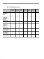
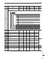
Manuals Related to the Σ-V Series
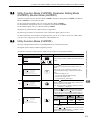
Refer to the following manuals as required.
Name
Selecting
Models and Ratings and
Peripheral Specifications
Devices
System
Design
Σ-V Series
SGMV/SGDV
User's Manual
Setup
Rotational Motor
(SIEPS80000043)
Σ-V Series
SGMV/SGDV
User's Manual
MECHATROLINK-II
Command
(SIEPS80000054)
Σ-V Series
SGMV/SGDV Catalog
(KAEPS80000042)
Σ-V Series
SGMV/SGDV
User’s Manual
Operation of Digital
Operator
(SIEPS80000055)
iv
9
9
Panels and
Wiring
Trial
Operation
9
9
Trial
Maintenance
Operation
and
and Servo
Inspection
Adjustment
9
9
9
9
9
9
Σ-V Series
AC SERVOPACK SGDV
Safety Precautions
(TOBPC71080010)
9
Σ Series
Digital Operator
Safety Precautions
(TOBPC73080000)
9
AC SERVOMOTOR
Safety Precautions
(TOBPC23020000)
9
Safety Information
The following conventions are used to indicate precautions in this manual. Failure to heed precautions provided in this manual can result in serious or possibly even fatal injury or damage to the products or to related
equipment and systems.
WARNING
CAUTION
PROHIBITED
MANDATORY
Indicates precautions that, if not heeded, could possibly result in loss of
life or serious injury.
Indicates precautions that, if not heeded, could result in relatively serious
or minor injury, damage to the product, or faulty operation.
In some situations, the precautions indicated could have series
consequences if not heeded.
Indicates prohibited actions that must not be performed. For example,
this symbol would be used to indicate that fire is prohibited as follows:
Indicates compulsory actions that must be performed. For example, this
symbol would be used as follows to indicate that grounding is
compulsory:
v
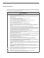
Safety Precautions
These safety precautions are very important. Read them before performing any procedures such as checking
products on delivery, storage and transportation, installation, wiring, operation and inspection, or disposal. Be
sure to always observe these precautions thoroughly.
WARNING
• Never touch any rotating motor parts while the motor is running.
Failure to observe this warning may result in injury.
• Before starting operation with a machine connected, make sure that an emergency stop can be
applied at any time.
Failure to observe this warning may result in injury or damage to the product.
• Never touch the inside of the SERVOPACKs.
Failure to observe this warning may result in electric shock.
• Do not remove the cover of the power supply terminal block while the power is ON.
Failure to observe this warning may result in electric shock.
• Do not touch terminals for five minutes after the power is turned OFF.
Residual voltage may cause electric shock.
• Do not touch terminals for five minutes after a voltage resistance test.
Residual voltage in the SERVOPACK may cause electric shock. When voltage has been completely discharged, the CHARGE lamp will turn OFF. Be sure to check the CHARGE lamp before performing the next
operation.
• Follow the procedures and instructions provided in this manual for trial operation.
Failure to do so may result not only in faulty operation and damage to equipment, but also in personal injury.
• The multi-turn output range for the Σ-V Series absolute position detecting system is different from
that of earlier systems (15-bit and 12-bit encoders). In particular, change the system to configure
the Σ series infinite-length positioning system with the Σ-V Series.
• The multi-turn limit value need not be changed except for special applications.
Changing it inappropriately or unintentionally can be dangerous.
• If the Multi-turn Limit Disagreement alarm occurs, check the setting of parameter Pn205 in the SERVOPACK to be sure that it is correct.
If Fn013 is executed when an incorrect value is set in Pn205, an incorrect value will be set in the encoder. The
alarm will disappear even if an incorrect value is set, but incorrect positions will be detected, resulting in a
dangerous situation where the machine will move to unexpected positions.
• Do not remove the front cover, cables, connectors, or optional items from the upper front of the
SERVOPACK while the power is ON.
Failure to observe this warning may result in electric shock.
• Do not damage, press, exert excessive force on, or place heavy objects on the cables.
Failure to observe this warning may result in electric shock, stopping operation of the product, or fire.
• Provide an appropriate stopping device on the machine side to ensure safety. The holding brake on
a servomotor with a brake is not a stopping device for ensuring safety.
Failure to observe this warning may result in injury.
• The person who designs a system using the safety function (Hard Wire Baseblock function) must
have full knowledge of the related safety standards and full understanding of the instructions in this
manual.
Failure to observe this warning may result in injury.
• Do not come close to the machine immediately after resetting a momentary power loss. The
machine may restart unexpectedly. Take appropriate measures to ensure safety against an unexpected restart.
Failure to observe this warning may result in injury.
• Connect the ground terminal according to local electrical codes (100 Ω or less for a SERVOPACK
with a 200 V power supply, 10 Ω or less for a SERVOPACK with a 400 V power supply).
Improper grounding may result in electric shock or fire.
• Installation, disassembly, or repair must be performed only by authorized personnel.
Failure to observe this warning may result in electric shock or injury.
vi
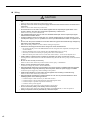
Storage and Transportation
CAUTION
• Do not store or install the product in the following locations.
Failure to observe this caution may result in fire, electric shock, or damage to the product.
• Locations subject to direct sunlight
• Locations subject to temperatures outside the range specified in the storage/installation temperature conditions
• Locations subject to humidity outside the range specified in the storage/installation humidity conditions
• Locations subject to condensation as the result of extreme changes in temperature
• Locations subject to corrosive or flammable gases
• Locations subject to dust, salts, or iron dust
• Locations subject to exposure to water, oil, or chemicals
• Locations subject to shock or vibration
• Do not hold the product by the cables or motor shaft while transporting it.
Failure to observe this caution may result in injury or malfunction.
• Do not place any load exceeding the limit specified on the packing box.
Failure to observe this caution may result in injury or malfunction.
• If disinfectants or insecticides must be used to treat packing materials such as wooden frames, pallets, or plywood, the packing materials must be treated before the product is packaged, and methods other than fumigation must be used.
Example: Heat treatment, where materials are kiln-dried to a core temperature of 56°C for 30
minutes or more.
If the electronic products, which include stand-alone products and products installed in machines, are packed
with fumigated wooden materials, the electrical components may be greatly damaged by the gases or fumes
resulting from the fumigation process. In particular, disinfectants containing halogen, which includes chlorine, fluorine, bromine, or iodine can contribute to the erosion of the capacitors.
Installation
CAUTION
• Never use the product in an environment subject to water, corrosive gases, inflammable gases, or
combustibles.
Failure to observe this caution may result in electric shock or fire.
• Do not step on or place a heavy object on the product.
Failure to observe this caution may result in injury.
• Do not cover the inlet or outlet ports and prevent any foreign objects from entering the product.
Failure to observe this caution may cause internal elements to deteriorate resulting in malfunction or fire.
• Be sure to install the product in the correct direction.
Failure to observe this caution may result in malfunction.
• Provide the specified clearances between the SERVOPACK and the control panel or with other
devices.
Failure to observe this caution may result in fire or malfunction.
• Do not apply any strong impact.
Failure to observe this caution may result in malfunction.
vii
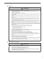
Wiring
CAUTION
• Do not connect a commercial power supply to the U, V, or W terminals for the servomotor connection.
Failure to observe this caution may result in injury or fire.
• Securely connect the main circuit power supply terminal screws and servomotor connection terminal screws.
Failure to observe this caution may result in fire.
• Do not bundle or run the main circuit cables together with the input/output signal cables or the
encoder cables in the same duct. Keep them separated by at least 30 cm.
Failure to do so may result in malfunction.
• Use shielded twisted-pair wires or multi-core shielded twisted-pair wires for input/output signal
cables and the encoder cables.
• I/O signal cables must be no longer than 3 m, encoder cables must be no longer than 20 m, and
control power supply (+24 V, 0 V) cables for a 400 V input SERVOPACK must be no longer than 20
m.
• Do not touch the power terminals for 5 minutes after turning power OFF because high voltage may
still remain in the SERVOPACK.
Make sure the charge indicator is out first before starting an inspection.
• Observe the following precautions when wiring main circuit terminal blocks.
• Do not turn ON the power to the SERVOPACK until all wiring has been completed, including the main
circuit terminals.
• Remove detachable main circuit terminals from the SERVOPACK prior to wiring.
• Insert only one main circuit cable per opening in the main circuit terminals.
• Make sure that no part of the core wire comes into contact with (i.e., short-circuit) adjacent wires.
• Install a battery at either the host controller or the battery unit of the encoder, but not both.
It is dangerous to install batteries at both ends simultaneously, because that sets up a loop circuit between the
batteries.
• Be sure to wire correctly and securely.
Failure to observe this caution may result in motor overrun, injury, or malfunction.
• Always use the specified power supply voltage.
An incorrect voltage may result in fire or malfunction.
• Take appropriate measures to ensure that the input power supply is supplied within the specified
voltage fluctuation range. Be particularly careful in places where the power supply is unstable.
An incorrect power supply may result in damage to the product.
• Install external breakers or other safety devices against short-circuiting in external wiring.
Failure to observe this caution may result in fire.
• Take appropriate and sufficient countermeasures for each form of potential interference when
installing systems in the following locations.
• Locations subject to static electricity or other forms of noise
• Locations subject to strong electromagnetic fields and magnetic fields
• Locations subject to possible exposure to radioactivity
• Locations close to power supplies
Failure to observe this caution may result in damage to the product.
• Do not reverse the polarity of the battery when connecting it.
Failure to observe this caution may damage the battery, the SERVOPACK, or cause an explosion.
• Wiring or inspection must be performed by a technical expert.
viii
Operation
CAUTION
• Always use the servomotor and SERVOPACK in one of the specified combinations.
Failure to observe this caution so may result in fire or malfunction.
• Conduct trial operation on the servomotor alone with the motor shaft disconnected from the
machine to avoid accidents.
Failure to observe this caution may result in injury.
• Before starting operation with a machine connected, change the settings to match the parameters
of the machine.
Starting operation without matching the proper settings may cause the machine to run out of control or malfunction.
• Do not frequently turn power ON and OFF. Do not turn power ON or OFF more than once per
minute.
Since the SERVOPACK has a capacitor in the power supply, a high charging current flows when power is
turned ON. Frequently turning power ON and OFF causes main power devices like capacitors and fuses to
deteriorate, resulting in unexpected problems.
• The dynamic brake function using reverse overtravel and forward overtravel does not work during
JOG operations using utility function Fn002 and origin search operations using utility function
Fn003.
• When using the servomotor for a vertical axis, install safety devices to prevent workpieces from falling due to alarms or overtravels. Set the servomotor so that it will stop in the zero clamp state when
overtravel occurs.
Failure to observe this caution may cause workpieces to fall due to overtravel.
• Be sure to set the correct moment of inertia ratio in the following cases.
• When not using tuning-less function.
• When not setting a moment of inertia ratio (Pn103)
• When using one-parameter tuning
Setting to an incorrect moment of inertia ratio may cause vibration.
• Do not touch the SERVOPACK heatsinks, regenerative resistor, or servomotor while power is ON or
soon after the power is turned OFF.
Failure to observe this caution may result in burns due to high temperatures.
• Do not make any extreme adjustments or setting changes of parameters.
Failure to observe this caution may result in injury or damage to the product due to unstable operation.
• When an alarm occurs, remove the cause, reset the alarm after confirming safety, and then resume
operation.
Failure to observe this caution may result in damage to the product, fire, or injury.
• Do not use the brake of the servomotor for braking.
Failure to observe this caution may result in malfunction.
• An alarm or warning may be generated if communications are executed with the host controller during operation using SigmaWin+ or the digital operator.
If an alarm or warning is generated, the process currently being executed may be aborted and the system may
stop.
Maintenance and Inspection
CAUTION
• Do not disassemble the SERVOPACK.
Failure to observe this caution may result in electric shock or injury.
• Do not attempt to change wiring while the power is ON.
Failure to observe this caution may result in electric shock or injury.
• When replacing the SERVOPACK, resume operation only after transferring the previous SERVOPACK parameters to the new SERVOPACK.
Failure to observe this caution may result in damage to the product.
ix
Disposal
CAUTION
• When disposing of the products, treat them as ordinary industrial waste.
General Precautions
Observe the following general precautions
to ensure safe application.
• The products shown in illustrations in this manual are sometimes shown without covers or protective guards.
Always replace the cover or protective guard as specified first, and then operate the products in accordance with
the manual.
• The drawings presented in this manual are typical examples and may not match the product you received.
• This manual is subject to change due to product improvement, specification modification, and manual improvement. When this manual is revised, the manual code is updated and the new manual is published as a next edition.
The edition number appears on the front and back covers.
• If the manual must be ordered due to loss or damage, inform your nearest Yaskawa representative or one of the
offices listed on the back of this manual.
• Yaskawa will not take responsibility for the results of unauthorized modifications of this product.
Yaskawa shall not be liable for any damages or troubles resulting from unauthorized modification.
x
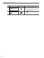
Applicable Standards
North American Safety Standards (UL)
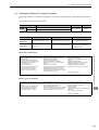
C
UL
R
R
US
C
LISTED
Model
UL∗ Standards
(UL File No.)
SERVOPACK
• SGDV
UL508C (E147823)
Servomotor
• SGMJV
• SGMAV
• SGMGV
UL1004 (E165827)
∗
US
Underwriters Laboratories Inc.
European Standards
Model
EMC Directive
Low Voltage
Directive
EMI
EMS
SERVOPACK
• SGDV
EN50178
EN61800-5-1
EN55011
class A group 1
EN61800-3
Servomotor
• SGMJV
• SGMAV
• SGMGV
IEC60034-1
IEC60034-5
IEC60034-8
IEC60034-9
EN55011
class A group 1
EN61800-3
∗ TÜV and SÜD Product Services GmbH
Note: Because SERVOPACKs and servomotors are built into machines, certification is required after installation in the
final product.
xi
Contents
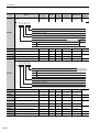
About this Manual . . . . . . . . . . . . . . . . . . . . . . . . . . . . . . . . . . . . . . . . . . . . . . . . . . . . . . . . iii
Safety Precautions. . . . . . . . . . . . . . . . . . . . . . . . . . . . . . . . . . . . . . . . . . . . . . . . . . . . . . . . vi
Applicable Standards . . . . . . . . . . . . . . . . . . . . . . . . . . . . . . . . . . . . . . . . . . . . . . . . . . . . . . xi
Chapter 1 Outline . . . . . . . . . . . . . . . . . . . . . . . . . . . . . . . . . . . . . . . . . . . .1-1
1.1 Σ-V Series SERVOPACKs . . . . . . . . . . . . . . . . . . . . . . . . . . . . . . . . . . . . . . . 1-2
1.2 Part Names . . . . . . . . . . . . . . . . . . . . . . . . . . . . . . . . . . . . . . . . . . . . . . . . . . 1-2
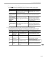
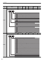
1.3 SERVOPACK Ratings and Specifications . . . . . . . . . . . . . . . . . . . . . . . . . . . 1-3
1.3.1 Ratings . . . . . . . . . . . . . . . . . . . . . . . . . . . . . . . . . . . . . . . . . . . . . . . . . . . . . . . . . . . . . . . . 1-3
1.3.2 Basic Specifications . . . . . . . . . . . . . . . . . . . . . . . . . . . . . . . . . . . . . . . . . . . . . . . . . . . . . . 1-4
1.3.3 MECHATROLINK-II Function Specifications . . . . . . . . . . . . . . . . . . . . . . . . . . . . . . . . . . . 1-6
1.4 Examples of Servo System Configurations . . . . . . . . . . . . . . . . . . . . . . . . . . 1-7
1.4.1 Connecting to SGDV-A11A SERVOPACK . . . . . . . . . . . . . . . . . . . . . . . . . . . . . . . . 1-7
1.4.2 Connecting to SGDV-D11A SERVOPACK . . . . . . . . . . . . . . . . . . . . . . . . . . . . . . . . 1-8
1.5 SERVOPACK Model Designation. . . . . . . . . . . . . . . . . . . . . . . . . . . . . . . . . . 1-9
1.6 Inspection and Maintenance . . . . . . . . . . . . . . . . . . . . . . . . . . . . . . . . . . . . 1-10
Chapter 2 Panel Display and
Operation of Digital Operator. . . . . . . . . . . . . . . . . . . . . . . . . . . . . . . . .2-1
2.1 Panel Display . . . . . . . . . . . . . . . . . . . . . . . . . . . . . . . . . . . . . . . . . . . . . . . . . 2-2
2.1.1 Status Display . . . . . . . . . . . . . . . . . . . . . . . . . . . . . . . . . . . . . . . . . . . . . . . . . . . . . . . . . . 2-2
2.1.2 Alarm and Warning Display . . . . . . . . . . . . . . . . . . . . . . . . . . . . . . . . . . . . . . . . . . . . . . . . 2-2
2.1.3 Mode Test without Motor Display . . . . . . . . . . . . . . . . . . . . . . . . . . . . . . . . . . . . . . . . . . . . 2-2
xii
2.2 Utility Function Mode (Fn), Parameter Setting Mode (Pn), Monitor
Mode (Un) . . . . . . . . . . . . . . . . . . . . . . . . . . . . . . . . . . . . . . . . . . . . . . 2-3
2.3 Utility Function Mode (Fn ) . . . . . . . . . . . . . . . . . . . . . . . . . . . . . . . . . . 2-3
2.4 Parameter Setting Mode (Pn). . . . . . . . . . . . . . . . . . . . . . . . . . . . . . . . 2-5
2.4.1 Parameter Setting Mode for Parameter Setting Type . . . . . . . . . . . . . . . . . . . . . . . . . . . . 2-5
2.4.2 Parameter Setting Mode for Function Selection Type . . . . . . . . . . . . . . . . . . . . . . . . . . . . 2-7
2.4.3 How to Read a Parameter Explanation . . . . . . . . . . . . . . . . . . . . . . . . . . . . . . . . . . . . . . . 2-8
2.5 Monitor Mode (Un) . . . . . . . . . . . . . . . . . . . . . . . . . . . . . . . . . . . . . . . 2-10
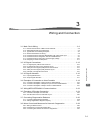
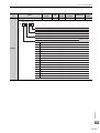
Chapter 3 Wiring and Connection . . . . . . . . . . . . . . . . . . . . . . . . . . . . . . . .3-1
3.1 Main Circuit Wiring. . . . . . . . . . . . . . . . . . . . . . . . . . . . . . . . . . . . . . . . . . . . . 3-2
3.1.1
3.1.2
3.1.3
3.1.4
3.1.5
3.1.6
3.1.7
3.1.8
Names and Functions of Main Circuit Terminals . . . . . . . . . . . . . . . . . . . . . . . . . . . . . . . . 3-2
SERVOPACK Main Circuit Wire Size. . . . . . . . . . . . . . . . . . . . . . . . . . . . . . . . . . . . . . . . . 3-3
Typical Main Circuit Wiring Examples . . . . . . . . . . . . . . . . . . . . . . . . . . . . . . . . . . . . . . . . 3-5
General Precautions for Wiring . . . . . . . . . . . . . . . . . . . . . . . . . . . . . . . . . . . . . . . . . . . . .3-6
Precautions When Using the SERVOPACK with a DC Power Input . . . . . . . . . . . . . . . . . 3-7
Precautions When Using More Than One SERVOPACK . . . . . . . . . . . . . . . . . . . . . . . . . 3-9
Precautions When Using 400 V Power Supply Voltage . . . . . . . . . . . . . . . . . . . . . . . . . . 3-10
Designing a Power ON Sequence . . . . . . . . . . . . . . . . . . . . . . . . . . . . . . . . . . . . . . . . . . 3-11
3.2 I/O Signal Connections . . . . . . . . . . . . . . . . . . . . . . . . . . . . . . . . . . . . . . . . 3-12
3.2.1
3.2.2
3.2.3
3.2.4
3.2.5
I/O Signal (CN1) Names and Functions. . . . . . . . . . . . . . . . . . . . . . . . . . . . . . . . . . . . . . 3-12
I/O Signal Connector (CN1) Terminal Layout . . . . . . . . . . . . . . . . . . . . . . . . . . . . . . . . . . 3-13
Safety Function Signal (CN8) Names and Functions. . . . . . . . . . . . . . . . . . . . . . . . . . . . 3-14
Safety Function Signal (CN8) Terminal Layout . . . . . . . . . . . . . . . . . . . . . . . . . . . . . . . . 3-14
Example of I/O Signal Connections . . . . . . . . . . . . . . . . . . . . . . . . . . . . . . . . . . . . . . . . . 3-15
3.3 I/O Signal Allocation. . . . . . . . . . . . . . . . . . . . . . . . . . . . . . . . . . . . . . . . . . . 3-16
3.3.1 Input Signal Allocation . . . . . . . . . . . . . . . . . . . . . . . . . . . . . . . . . . . . . . . . . . . . . . . . . . . 3-16
3.3.2 Output Signal Allocation. . . . . . . . . . . . . . . . . . . . . . . . . . . . . . . . . . . . . . . . . . . . . . . . . . 3-17
3.4 Examples of Connection to Host Controller . . . . . . . . . . . . . . . . . . . . . . . . . 3-19
3.4.1 Connection Examples of Input Circuits to SERVOPACK . . . . . . . . . . . . . . . . . . . . . . . . . 3-19
3.4.2 Connection Examples of Sequence Input Circuits to SERVOPACK . . . . . . . . . . . . . . . . 3-20
3.4.3 Connection Examples of Output Circuits to SERVOPACK . . . . . . . . . . . . . . . . . . . . . . . 3-21
3.5 Wiring MECHATROLINK-II Communications . . . . . . . . . . . . . . . . . . . . . . . 3-23
3.6 Examples of Encoder Connection . . . . . . . . . . . . . . . . . . . . . . . . . . . . . . . . 3-24
3.6.1 Connection Example of an Encoder. . . . . . . . . . . . . . . . . . . . . . . . . . . . . . . . . . . . . . . . . 3-24
3.6.2 CN2 Encoder Connector Terminal Layout . . . . . . . . . . . . . . . . . . . . . . . . . . . . . . . . . . . . 3-25
3.7 Connecting Regenerative Resistors . . . . . . . . . . . . . . . . . . . . . . . . . . . . . . 3-26
3.7.1 Connecting Regenerative Resistors. . . . . . . . . . . . . . . . . . . . . . . . . . . . . . . . . . . . . . . . . 3-26
3.7.2 Setting Regenerative Registor Capacity . . . . . . . . . . . . . . . . . . . . . . . . . . . . . . . . . . . . . 3-27
3.8 Noise Control and Measures for Harmonic Suppression. . . . . . . . . . . . . . . 3-28
3.8.1 Wiring for Noise Control . . . . . . . . . . . . . . . . . . . . . . . . . . . . . . . . . . . . . . . . . . . . . . . . . . 3-28
3.8.2 Precautions on Connecting Noise Filter . . . . . . . . . . . . . . . . . . . . . . . . . . . . . . . . . . . . . . 3-30
3.8.3 Connecting DC Reactor for Harmonic Suppression. . . . . . . . . . . . . . . . . . . . . . . . . . . . . 3-32
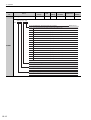
Chapter 4 Operation . . . . . . . . . . . . . . . . . . . . . . . . . . . . . . . . . . . . . . . . . .4-1
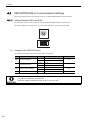
4.1 MECHATROLINK-II Communications Settings . . . . . . . . . . . . . . . . . . . . . . . 4-2
4.1.1 Setting Switches SW1 and SW2 . . . . . . . . . . . . . . . . . . . . . . . . . . . . . . . . . . . . . . . . . . . . 4-2
4.2 MECHATROLINK-II Commands . . . . . . . . . . . . . . . . . . . . . . . . . . . . . . . . . . 4-3
4.3 Setting Common Basic Functions . . . . . . . . . . . . . . . . . . . . . . . . . . . . . . . . . 4-4
4.3.1
4.3.2
4.3.3
4.3.4
4.3.5
4.3.6
Servomotor Rotation Direction . . . . . . . . . . . . . . . . . . . . . . . . . . . . . . . . . . . . . . . . . . . . . . 4-4
Overtravel. . . . . . . . . . . . . . . . . . . . . . . . . . . . . . . . . . . . . . . . . . . . . . . . . . . . . . . . . . . . . . 4-5
Holding Brakes. . . . . . . . . . . . . . . . . . . . . . . . . . . . . . . . . . . . . . . . . . . . . . . . . . . . . . . . . . 4-7
Stopping Method for Servomotor after Servo OFF or Alarm Occurrence. . . . . . . . . . . . . 4-12
Power Loss Settings . . . . . . . . . . . . . . . . . . . . . . . . . . . . . . . . . . . . . . . . . . . . . . . . . . . . 4-14
Torque Limit Function for Low Power Supply Voltage for Main Circuit (SEMI-F47 Function)
4-15
4.4 Trial Operation . . . . . . . . . . . . . . . . . . . . . . . . . . . . . . . . . . . . . . . . . . . . . . . 4-16
4.4.1 Inspection and Checking before Trial Operation . . . . . . . . . . . . . . . . . . . . . . . . . . . . . . . 4-16
4.4.2 Trial Operation via MECHATROLINK-II . . . . . . . . . . . . . . . . . . . . . . . . . . . . . . . . . . . . . . . . . . 4-18
4.4.3 Electronic Gear . . . . . . . . . . . . . . . . . . . . . . . . . . . . . . . . . . . . . . . . . . . . . . . . . . . . . . . . 4-19
xiii
4.5 Test Without Motor Function. . . . . . . . . . . . . . . . . . . . . . . . . . . . . . . . . . . . . 4-22
4.5.1 Limitations . . . . . . . . . . . . . . . . . . . . . . . . . . . . . . . . . . . . . . . . . . . . . . . . . . . . . . . . . . . . 4-22
4.5.2 Related Parameters . . . . . . . . . . . . . . . . . . . . . . . . . . . . . . . . . . . . . . . . . . . . . . . . . . . . . 4-24
4.5.3 Digital Operator Display during Testing without Motor . . . . . . . . . . . . . . . . . . . . . . . . . . . 4-24
4.6 Absolute Encoders . . . . . . . . . . . . . . . . . . . . . . . . . . . . . . . . . . . . . . . . . . . . 4-25
4.6.1
4.6.2
4.6.3
4.6.4
4.6.5
4.6.6
4.6.7
Encoder Resolutions . . . . . . . . . . . . . . . . . . . . . . . . . . . . . . . . . . . . . . . . . . . . . . . . . . . . 4-25
Absolute Encoder Data Backup . . . . . . . . . . . . . . . . . . . . . . . . . . . . . . . . . . . . . . . . . . . . 4-26
Encoder Battery Alarm (A. 830) . . . . . . . . . . . . . . . . . . . . . . . . . . . . . . . . . . . . . . . . . . . . 4-27
Absolute Encoder Setup . . . . . . . . . . . . . . . . . . . . . . . . . . . . . . . . . . . . . . . . . . . . . . . . . 4-28
Multiturn Limit Setting. . . . . . . . . . . . . . . . . . . . . . . . . . . . . . . . . . . . . . . . . . . . . . . . . . . . 4-29
Multiturn Limit Disagreement Alarm (A.CC0) . . . . . . . . . . . . . . . . . . . . . . . . . . . . . . . . . . 4-30
Absolute Encoder Origin Offset . . . . . . . . . . . . . . . . . . . . . . . . . . . . . . . . . . . . . . . . . . . . 4-31
4.7 Safety Function . . . . . . . . . . . . . . . . . . . . . . . . . . . . . . . . . . . . . . . . . . . . . . 4-32
4.7.1
4.7.2
4.7.3
4.7.4
4.7.5
Hard Wire Base Block (HWBB) Function . . . . . . . . . . . . . . . . . . . . . . . . . . . . . . . . . . . . . 4-32
External Device Monitor (EDM1) . . . . . . . . . . . . . . . . . . . . . . . . . . . . . . . . . . . . . . . . . . . 4-37
Application Example of Safety Functions. . . . . . . . . . . . . . . . . . . . . . . . . . . . . . . . . . . . . 4-39
Confirming Safety Functions . . . . . . . . . . . . . . . . . . . . . . . . . . . . . . . . . . . . . . . . . . . . . . 4-40
Precautions for Safety Functions . . . . . . . . . . . . . . . . . . . . . . . . . . . . . . . . . . . . . . . . . . . 4-40
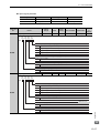
Chapter 5 Adjustments . . . . . . . . . . . . . . . . . . . . . . . . . . . . . . . . . . . . . . . .5-1
5.1 Adjustments and Basic Adjustment Procedure . . . . . . . . . . . . . . . . . . . . . . . 5-3
5.1.1
5.1.2
5.1.3
5.1.4
Adjustments . . . . . . . . . . . . . . . . . . . . . . . . . . . . . . . . . . . . . . . . . . . . . . . . . . . . . . . . . . . . 5-3
Basic Adjustment Procedure . . . . . . . . . . . . . . . . . . . . . . . . . . . . . . . . . . . . . . . . . . . . . . . 5-4
Monitoring Analog Signals . . . . . . . . . . . . . . . . . . . . . . . . . . . . . . . . . . . . . . . . . . . . . . . . . 5-5
Safety Precautions on Adjustment of Servo Gains . . . . . . . . . . . . . . . . . . . . . . . . . . . . . . 5-8
5.2 Tuning-less Function (Fn200). . . . . . . . . . . . . . . . . . . . . . . . . . . . . . . . . . . . 5-11
5.2.1 Tuning-less Function . . . . . . . . . . . . . . . . . . . . . . . . . . . . . . . . . . . . . . . . . . . . . . . . . . . . 5-11
5.2.2 Tuning-less Operating Procedure . . . . . . . . . . . . . . . . . . . . . . . . . . . . . . . . . . . . . . . . . . 5-12
5.3 Advanced Autotuning (Fn201) . . . . . . . . . . . . . . . . . . . . . . . . . . . . . . . . . . . 5-15
5.3.1 Advanced Autotuning . . . . . . . . . . . . . . . . . . . . . . . . . . . . . . . . . . . . . . . . . . . . . . . . . . . . 5-15
5.3.2 Advanced Autotuning Procedure . . . . . . . . . . . . . . . . . . . . . . . . . . . . . . . . . . . . . . . . . . 5-20
5.3.3 Related Parameters . . . . . . . . . . . . . . . . . . . . . . . . . . . . . . . . . . . . . . . . . . . . . . . . . . . . . 5-24
5.4 Advanced Autotuning by Reference (Fn202) . . . . . . . . . . . . . . . . . . . . . . . . 5-25
5.4.1 Advanced Autotuning by Reference. . . . . . . . . . . . . . . . . . . . . . . . . . . . . . . . . . . . . . . . . 5-25
5.4.2 Advanced Autotuning by Reference Procedure . . . . . . . . . . . . . . . . . . . . . . . . . . . . . . . 5-29
5.4.3 Related Parameters . . . . . . . . . . . . . . . . . . . . . . . . . . . . . . . . . . . . . . . . . . . . . . . . . . . . . 5-31
5.5 One-parameter Tuning (Fn203) . . . . . . . . . . . . . . . . . . . . . . . . . . . . . . . . . . 5-32
5.5.1
5.5.2
5.5.3
5.5.4
One-parameter Tuning . . . . . . . . . . . . . . . . . . . . . . . . . . . . . . . . . . . . . . . . . . . . . . . . . . . 5-32
One-parameter Tuning Procedure . . . . . . . . . . . . . . . . . . . . . . . . . . . . . . . . . . . . . . . . . . 5-35
One-parameter Tuning Example . . . . . . . . . . . . . . . . . . . . . . . . . . . . . . . . . . . . . . . . . . . 5-38
Related Parameters . . . . . . . . . . . . . . . . . . . . . . . . . . . . . . . . . . . . . . . . . . . . . . . . . . . . . 5-39
5.6 Anti-Resonance Control Adjustment Function (Fn204) . . . . . . . . . . . . . . . . 5-40
5.6.1 Anti-Resonance Control Adjustment Function . . . . . . . . . . . . . . . . . . . . . . . . . . . . . . . . . 5-40
5.6.2 Anti-Resonance Control Adjustment Function Operating Procedure. . . . . . . . . . . . . . . . 5-41
5.6.3 Related Parameters . . . . . . . . . . . . . . . . . . . . . . . . . . . . . . . . . . . . . . . . . . . . . . . . . . . . . 5-45
5.7 Vibration Suppression Function (Fn205) . . . . . . . . . . . . . . . . . . . . . . . . . . . 5-46
5.7.1 Vibration Suppression Function . . . . . . . . . . . . . . . . . . . . . . . . . . . . . . . . . . . . . . . . . . . . 5-46
5.7.2 Vibration Suppression Function Operating Procedure . . . . . . . . . . . . . . . . . . . . . . . . . . . 5-47
5.7.3 Related Parameters . . . . . . . . . . . . . . . . . . . . . . . . . . . . . . . . . . . . . . . . . . . . . . . . . . . . . 5-49
5.8 Servo Gain Adjustment Application Function . . . . . . . . . . . . . . . . . . . . . . . . 5-50
5.8.1
5.8.2
5.8.3
5.8.4
5.8.5
5.8.6
Feedforward Reference . . . . . . . . . . . . . . . . . . . . . . . . . . . . . . . . . . . . . . . . . . . . . . . . . . 5-51
Using the Mode Switch (P/PI Switching) . . . . . . . . . . . . . . . . . . . . . . . . . . . . . . . . . . . . . 5-51
Switching Gain Settings . . . . . . . . . . . . . . . . . . . . . . . . . . . . . . . . . . . . . . . . . . . . . . . . . . 5-55
Torque Reference Filter . . . . . . . . . . . . . . . . . . . . . . . . . . . . . . . . . . . . . . . . . . . . . . . . . . 5-59
Position Integral Time Constant . . . . . . . . . . . . . . . . . . . . . . . . . . . . . . . . . . . . . . . . . . . . 5-61
Friction Compensation . . . . . . . . . . . . . . . . . . . . . . . . . . . . . . . . . . . . . . . . . . . . . . . . . . . 5-62
Chapter 6 Utility Functions (Fn) . . . . . . . . . . . . . . . . . . . . . . . . . . . . .6-1
6.1 List of Utility Functions . . . . . . . . . . . . . . . . . . . . . . . . . . . . . . . . . . . . . . . . . . 6-2
6.2 Alarm History Display (Fn000) . . . . . . . . . . . . . . . . . . . . . . . . . . . . . . . . . . . . 6-3
6.3 JOG Operation (Fn002) . . . . . . . . . . . . . . . . . . . . . . . . . . . . . . . . . . . . . . . . . 6-4
xiv
6.4 Origin Search (Fn003) . . . . . . . . . . . . . . . . . . . . . . . . . . . . . . . . . . . . . . . . . . 6-6
6.5 Program JOG Operation (Fn004) . . . . . . . . . . . . . . . . . . . . . . . . . . . . . . . . . 6-8
6.6 Initializing Parameter Settings (Fn005) . . . . . . . . . . . . . . . . . . . . . . . . . . . . 6-13
6.7 Clearing Alarm History (Fn006) . . . . . . . . . . . . . . . . . . . . . . . . . . . . . . . . . . 6-14
6.8 Manual Zero-adjustment of Analog Monitor Output (Fn00C). . . . . . . . . . . . 6-15
6.9 Manual Gain-adjustment of Analog Monitor Output (Fn00D). . . . . . . . . . . . 6-17
6.10 Automatic Offset-Signal Adjustment of the Motor Current Detection (Fn00E) 619
6.11 Manual Offset-Signal Adjustment of the Motor Current Detection (Fn00F) 6-20
6.12 Write Prohibited Setting (Fn010) . . . . . . . . . . . . . . . . . . . . . . . . . . . . . . . . 6-21
6.13 Servomotor Model Display (Fn011) . . . . . . . . . . . . . . . . . . . . . . . . . . . . . . 6-23
6.14 Software Version Display (Fn012) . . . . . . . . . . . . . . . . . . . . . . . . . . . . . . . 6-24
6.15 Resetting Configuration Error of Option Card (Fn014) . . . . . . . . . . . . . . . 6-25
6.16 Vibration Detection Level Initialization (Fn01B) . . . . . . . . . . . . . . . . . . . . . 6-26
6.17 Display of SERVOPACK and Servomotor ID (Fn01E) . . . . . . . . . . . . . . . . 6-28
6.18 EasyFFT (Fn206). . . . . . . . . . . . . . . . . . . . . . . . . . . . . . . . . . . . . . . . . . . . 6-29
6.19 Online Vibration Monitor (Fn207). . . . . . . . . . . . . . . . . . . . . . . . . . . . . . . . 6-33
6.20 Origin Setting (Fn020) . . . . . . . . . . . . . . . . . . . . . . . . . . . . . . . . . . . . . . . . 6-35
6.21 Software Reset (Fn030). . . . . . . . . . . . . . . . . . . . . . . . . . . . . . . . . . . . . . . 6-36
Chapter 7 Monitor Modes (Un) . . . . . . . . . . . . . . . . . . . . . . . . . . . . .7-1
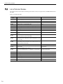
7.1 List of Monitor Modes. . . . . . . . . . . . . . . . . . . . . . . . . . . . . . . . . . . . . . . . . . . 7-2
7.2 Monitor Mode Display . . . . . . . . . . . . . . . . . . . . . . . . . . . . . . . . . . . . . . . . . . 7-3
Chapter 8 Fully-closed Loop Control. . . . . . . . . . . . . . . . . . . . . . . . . . . . . .8-1
8.1 System Configuration and Connection Example for SERVOPACK with Fullyclosed Loop Control. . . . . . . . . . . . . . . . . . . . . . . . . . . . . . . . . . . . . . . . . . . . 8-2
8.1.1
8.1.2
8.1.3
8.1.4
8.1.5
8.1.6
8.1.7
8.1.8
System Configuration. . . . . . . . . . . . . . . . . . . . . . . . . . . . . . . . . . . . . . . . . . . . . . . . . . . . . 8-2
Internal Configuration of Fully-closed Loop Control . . . . . . . . . . . . . . . . . . . . . . . . . . . . . . 8-3
Serial Converter Unit . . . . . . . . . . . . . . . . . . . . . . . . . . . . . . . . . . . . . . . . . . . . . . . . . . . . . 8-4
Analog Signal Input Timing . . . . . . . . . . . . . . . . . . . . . . . . . . . . . . . . . . . . . . . . . . . . . . . . 8-5
Connection Example of External Encoder by Heidenhain . . . . . . . . . . . . . . . . . . . . . . . . . 8-6
Connection Example of External Encoder by Renishaw . . . . . . . . . . . . . . . . . . . . . . . . . . 8-7
Connection Example of External Encoder by Mitutoyo . . . . . . . . . . . . . . . . . . . . . . . . . . . 8-8
Encoder Output Pulse Signals from SERVOPACK with a External Encoder by Renishaw 8-8
8.2 Related Parameters . . . . . . . . . . . . . . . . . . . . . . . . . . . . . . . . . . . . . . . . . . . 8-10
8.2.1
8.2.2
8.2.3
8.2.4
8.2.5
8.2.6
8.2.7
8.2.8
Setting Order of Related Parameters. . . . . . . . . . . . . . . . . . . . . . . . . . . . . . . . . . . . . . . . 8-10
Speed Feedback Method during Fully-closed Loop Control . . . . . . . . . . . . . . . . . . . . . . 8-10
Motor Rotation Direction. . . . . . . . . . . . . . . . . . . . . . . . . . . . . . . . . . . . . . . . . . . . . . . . . . 8-11
Sine Wave Pitch (Frequency) for an External Encoder . . . . . . . . . . . . . . . . . . . . . . . . . . 8-12
Number of Encoder Output Pulses (PAO, PBO, and PCO) from the SERVOPACK . . . . 8-13
Electronic Gear . . . . . . . . . . . . . . . . . . . . . . . . . . . . . . . . . . . . . . . . . . . . . . . . . . . . . . . . 8-14
Alarm Detection . . . . . . . . . . . . . . . . . . . . . . . . . . . . . . . . . . . . . . . . . . . . . . . . . . . . . . . . 8-14
Analog Monitor Signal . . . . . . . . . . . . . . . . . . . . . . . . . . . . . . . . . . . . . . . . . . . . . . . . . . . 8-15
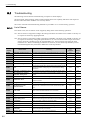
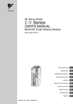
Chapter 9 Troubleshooting . . . . . . . . . . . . . . . . . . . . . . . . . . . . . . . . . . . . .9-1
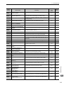
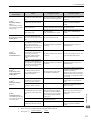
9.1 Troubleshooting . . . . . . . . . . . . . . . . . . . . . . . . . . . . . . . . . . . . . . . . . . . . . . . 9-2
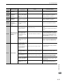
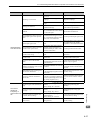
9.1.1 List of Alarms . . . . . . . . . . . . . . . . . . . . . . . . . . . . . . . . . . . . . . . . . . . . . . . . . . . . . . . . . . . 9-2
9.1.2 Troubleshooting of Alarms . . . . . . . . . . . . . . . . . . . . . . . . . . . . . . . . . . . . . . . . . . . . . . . . . 9-6
9.2 Warning Displays . . . . . . . . . . . . . . . . . . . . . . . . . . . . . . . . . . . . . . . . . . . . . 9-22
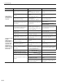
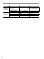
9.2.1 List of Warnings . . . . . . . . . . . . . . . . . . . . . . . . . . . . . . . . . . . . . . . . . . . . . . . . . . . . . . . . 9-22
9.2.2 Troubleshooting of Warnings . . . . . . . . . . . . . . . . . . . . . . . . . . . . . . . . . . . . . . . . . . . . . . 9-23
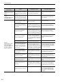
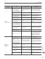
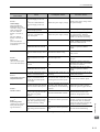
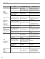
9.3 Troubleshooting Malfunction Based on Operation and Conditions of the Servomotor . . . . . . . . . . . . . . . . . . . . . . . . . . . . . . . . . . . . . . . . . . . . . . . . . . . . . . 9-26
Chapter 10 Appendix. . . . . . . . . . . . . . . . . . . . . . . . . . . . . . . . . . . . . . . . .10-1
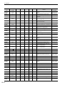
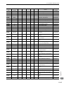
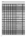
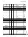
10.1 List of Parameters . . . . . . . . . . . . . . . . . . . . . . . . . . . . . . . . . . . . . . . . . . . 10-2
xv
10.1.1 Utility Functions . . . . . . . . . . . . . . . . . . . . . . . . . . . . . . . . . . . . . . . . . . . . . . . . . . . . . . . 10-2
10.1.2 Parameters. . . . . . . . . . . . . . . . . . . . . . . . . . . . . . . . . . . . . . . . . . . . . . . . . . . . . . . . . . . 10-3
10.2 Monitor Modes . . . . . . . . . . . . . . . . . . . . . . . . . . . . . . . . . . . . . . . . . . . . . 10-32
10.3 Parameter Recording Table . . . . . . . . . . . . . . . . . . . . . . . . . . . . . . . . . . . 10-33
Revision History
xvi
1
Outline
1.1 S-V Series SERVOPACKs . . . . . . . . . . . . . . . . . . . . . . . . . . . . . . . . . . . . . 1-2
1.2 Part Names . . . . . . . . . . . . . . . . . . . . . . . . . . . . . . . . . . . . . . . . . . . . . . . . 1-2
1.3 SERVOPACK Ratings and Specifications . . . . . . . . . . . . . . . . . . . . . . . . . 1-3
1.3.1 Ratings . . . . . . . . . . . . . . . . . . . . . . . . . . . . . . . . . . . . . . . . . . . . . . . . . . . . . . . . . . . . 1-3
1.3.2 Basic Specifications . . . . . . . . . . . . . . . . . . . . . . . . . . . . . . . . . . . . . . . . . . . . . . . . . . 1-4
1.3.3 MECHATROLINK-II Function Specifications . . . . . . . . . . . . . . . . . . . . . . . . . . . . . . . . 1-6
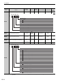
1.4 Examples of Servo System Configurations . . . . . . . . . . . . . . . . . . . . . . . . 1-7
1.4.1 Connecting to SGDV-oooA11A SERVOPACK . . . . . . . . . . . . . . . . . . . . . . . . . . . . . . 1-7
1.4.2 Connecting to SGDV-oooD11A SERVOPACK . . . . . . . . . . . . . . . . . . . . . . . . . . . . . . 1-8
1.6 Inspection and Maintenance . . . . . . . . . . . . . . . . . . . . . . . . . . . . . . . . . . 1-10
Outline
1.5 SERVOPACK Model Designation . . . . . . . . . . . . . . . . . . . . . . . . . . . . . . . 1-9
1
1-1
1 Outline
1.1
Σ-V Series SERVOPACKs
The Σ-V Series SERVOPACKs are designed for applications that require frequent high-speed, high-precision positioning. The SERVOPACK makes the most of machine performance in the shortest time possible, thus contributing to improving productivity.
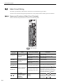
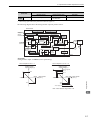
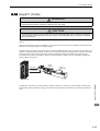
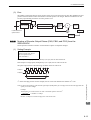
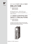
1.2
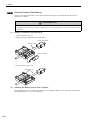
Part Names
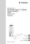
This section describes the part names of SGDV type SERVOPACK for MECHATROLINK-II communications reference.
With front cover open
Serial number
CN5 Analog monitor connector
Used to monitor motor speed, torque
reference, and other values through
a special cable (option).
5.1.3 Analog
Monitoring
Analog Signals.
Refer to 6.1.3
Monitor.
Rotary switch (SW 1)
Used to set the MECHATROLINK-II
station address.
Refer to 4.1.1 Setting Switches SW1 and SW2.
DIP switch (SW 2)
Used to set MECHATROLINK-II communications.
Refer to 4.1.1 Setting Switches SW1 and SW2.
Panel display
Indicates the servo status with 7-segment LEDs.
Refer to
to 2.1.1
2.1.1 Status
Status Display
Display.Mode
Refer
Input voltage
Front cover
SERVOPACK model
Charge indicator
Lights when the main circuit power supply is ON
and stays lit as long as the internal capacitor
remains charged. Therefore, do not touch the
SERVOPACK even after the power supply is
turned OFF if the indicator is lit.
It may result in electric shock.
Main circuit power
supply terminals
Used for main circuit power supply input.
Refer to 3.1 Main Circuit Wiring.
Control power
supply Terminals
Used for control power supply input.
Refer to 3.1 Main Circuit Wiring.
Regenerative
resistor connecting terminals
Connects external regenerative resistors.
DC reactor terminals for harmonic suppression
Connects DC reactor for harmonic suppression.
Referto
to3.8.3
3.8.3 Connecting
Connecting DC Reactor for Harmonic
Refer
Hormonic
Suppression.
Suppression.
Servomotor terminals
Connects the main circuit cable for servomotor.
Refer to 3.1 Main Circuit Wiring.
Ground terminal
Be sure to connect to protect against electrical shock.
Refer to 3.1 Main Circuit Wiring.
1-2
Refer to 1.5 SERVOPACK Model Designation.
MECHATROLINK-II communications connectors
Connects MECHATROLINK-II -supported devices.
Refer to
to 3.5
3.5 Wiring MECHATROLINK-II CommunicaRefer
tions.
CN3 Connector for digital operator
Connects a digital operator
(option, JUSP-OP05A-1-E).
Refer to Σ-V series SGMV/SGDV Catalog
(KAEPS80000042) and
Σ-V series SGM/SGDV User's Manual ,
Operation of Digital Operator (SIEPS80000055).
CN7 Connector for personal computer
Communicates with a
personal computer.
Use the connection cable (JZSP-CVS06-02-E).
CN1 I/O signal connector
Used for reference input signals and
sequence I/O signals.
Refer to 3.2 I/O Signal Connections.
CN8 Connector for safety function devices
Connects a safety function device.
Note: When not using the safety function, use the
SERVOPACK with the safety function jumper
connector (JZSP-CVH05-E, provided as an
accessory) inserted. For the connecting
refer
to 3.2.3
Function
Signal (CN8)
method,
referSafety
to 3.2.3
Safety Function
Signal
.
Names
and Functions
(CN8) Names
and Function.
For the operation,
Refertoto4.6
4.7Safety
SafetyFunction.
Function.
refer
CN2 Encoder connector
Connects the encoder in the SERVOPACK.
Refer to
to 3.6
3.6 Examples
Examples of
of Encoder
Encoder Connection.
Refer
1.3 SERVOPACK Ratings and Specifications
1.3
SERVOPACK Ratings and Specifications
This section describes the ratings and specifications of SERVOPACKs.
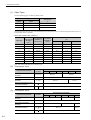
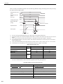
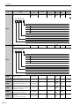
1.3.1
Ratings
Ratings of SERVOPACKs are as shown below.
(1) 200 VAC Rating
SGDV (200 VAC)
200 V
Input
Power
Supply
R70
R90
1R6
2R8
3R8
5R5
Continuous Output
Current [Arms]
0.66
0.91
1.6
2.8
3.8
5.5
Max. Output
Current [Arms]
2.1
2.9
6.5
9.3
11.0
16.9
200 V
Main
Circuit
Three-phase, 200 to 230 VAC
Control
Circuit
Single-phase, 200 to 230 VAC
Overvoltage
Category
+10%
–15% ,
50/60 Hz
+10%
–15% ,
50/60 Hz
III
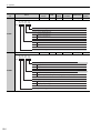
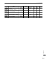
SGDV (400 VAC)
400 V
Input
Power
Supply
1R9
3R5
5R4
8R4
120
170
Continuos Output
Current [Arms]
1.9
3.5
5.4
8.4
11.9
16.5
Max. Output
Current [Arms]
5.5
8.5
14
20
28
42
400 V
Main
Circuit
Three-phase, 380 to 480 VAC +10%
–15%, 50/60 Hz
Control
Circuit
24 VDC ±15%
Overvoltage
Category
III
Outline
(2) 400 VAC Rating
1
1-3
1 Outline
1.3.2 Basic Specifications
1.3.2
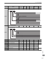
Basic Specifications
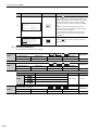
Basic specifications of SERVOPACKs are shown below.
Control Method
Single or three-phase full-wave rectification IGBT-PWM (sine-wave
driven)
Feedback
Serial encoder:
13-bit (incremental), 20-bit (incremental/absolute)
Operating
Conditions
Ambient/Storage
Temperature
0 to +55°C/ -20 to +85°C
Ambient/Storage
Humidity
90% RH or less (with no condensation)
Vibration/Shock
Resistance
4.9 m/s2 / 19.8 m/s2
Protection Class/
Pollution Degree
Protection class: IP1X, Pollution degree: 2
An environment that satisfies the following conditions.
• Free of corrosive or explosive gases
• Free of exposure to water, oil or chemicals
• Free of dust, salts or iron dust
Altitude
1000 m or less
Others
Free of static electricity, strong electromagnetic fields, magnetic
fields or exposure to radioactivity
Applicable Standards
UL508C
EN50178, EN55011 group1 classA, EN61000-6-3
Configuration
Base-mounted *1
Speed Control Range
Performance
Speed
Regulation∗2
Load
Regulation
0 to 100% load: ±0.01% max. (at rated speed)
Voltage
Regulation
Rated voltage ±10%: 0% (at rated speed)
Temperature
Regulation
25 ± 25 °C: ±0.1% max. (at rated speed)
Torque Control
Tolerance
(Repeatability)
±1%
Soft Start Time
Setting
0 to 10 s (Can be set individually for acceleration and deceleration.)
Encoder Output Pulses
Phase-A, -B, -C: line driver
Encoder output pulse: any setting ratio
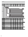
Sequence
Input
I/O
Signals
Number of
Channels
7 ch
Functions
The signal allocation and positive/negative logic can be modified.
Homing deceleration switch signal (/DEC), external latch signals
(/EXT 1 to 3), forward run prohibited (P-OT), reverse run
prohibited (N-OT), forward torque limit (/P-CL), reverse torque
limit (/N-CL)
Fixed Output
Servo alarm (ALM)
Number of
Channels
4 ch
Functions
The signal allocation and positive/negative logic can be modified.
Positioning completion (/COIN), speed coincidence detection (/VCMP), servomotor rotation detection (/TGON), servo ready (/SRDY), torque limit detection (/CLT), speed limit detection (/VLT),
brake interlock (/BK), warning (/WARN), near (/NEAR)
Sequence
Output
1-4
1:5000
1.3 SERVOPACK Ratings and Specifications
Interface
Communications
Function
Digital operator (JUSP-OP05A-1-E), personal computer (can be connected with SigmaWin+), etc.
1:N
N = Up to 15 stations possible at RS422A
Communications
RS422A
Communications
USB
Communications
Axis Address
Setting
Set by parameter
Function
Status display, parameter setting, tuning function, utility function,
parameter copy function
Interface
Personal computer (can be connected with SigmaWin+.)
Communications
Complys with standard USB1.1. (12 Mbps)
Standard
Function
Status display, parameter setting, tuning function, utility function
LED Display
CHARGE, five 7-segment LEDs
Analog Monitor (CN5)
Number of channels: 2 ch
Output voltage: ± 10V DC (linearity effective range ± 8V)
Resolution: 16 bit
Accuracy: ± 20 mV (Typ)
Max. allowable load current: ± 10 mA
Settling time (± 1%): 1.2 ms (Typ)
Dynamic Brake (DB)
Operated at main power OFF, servo alarm, servo OFF or overtravel
Regenerative Processing
Built-in or external regenerative resistor (option)
Overtravel Prevention (OT)
Dynamic brake stop at P-OT or N-OT, deceleration to a stop, or free
run to a stop
Protection Function
Overcurrent, overvoltage, insufficient voltage, overload, regeneration error, and so on.
Utility Function
Gain adjustment, alarm history, JOG operation, origin search, and so
on.
Option Card Adding
Function
Input
/HWBB1, /HWBB2: Baseblock signal for power module
Output
EDM1: Monitoring status of internal safety circuit (fixed output)
Fully-closed
Loop Interface
Card
Serial communications interface for fully-closed loop control
Outline
Safety Function
∗1. Rack mounting and duct-ventilated type available as an option.
∗2. Speed regulation is defined as follows:
Speed regulation
=
No-load motor speed - Total load motor speed
Rated motor speed
× 100%
1
The motor speed may change due to voltage variations or amplifier drift and changes in processing resistance
due to temperature variation. The ratio of speed changes to the rated speed represent speed regulation due to
voltage and temperature variations.
1-5
1 Outline
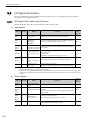
1.3.3 MECHATROLINK-II Function Specifications
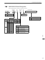
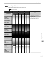
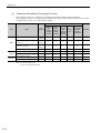
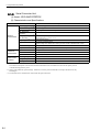
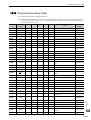
1.3.3
MECHATROLINK-II Function Specifications
The following table shows the basic specifications of MECHATROLINK-II.
Function
MECHATROLINK-II
Communication
Communication
Protocol
MECHATROLINK-II
Station Address
41H to 5FH (Max. number of stations: 30)
Baud Rate
10 Mpbs,4 Mpbs
Transmission Cycle
250 μs,0.5 ms to 4.0 ms (Multiples of 0.5 ms)
Number of Words in
Link Communication
Selections: 17 byte per station or 32 byte per station DIP
switch (SW2)
Control Method
Position, speed, or torque control with MECHATROLINKII communication
Reference Input
MECHATROLINK-II,MECHATROLINK-II commands
(sequence, motion, data setting/reference, monitoring, or
adjustment)
Reference Method
1-6
Specifications
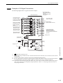
1.4 Examples of Servo System Configurations
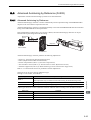
1.4
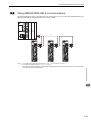
Examples of Servo System Configurations
This section describes examples of basic servo system configuration.
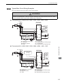
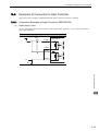
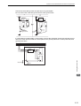
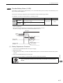
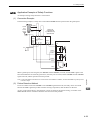
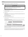
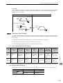
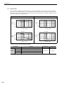
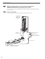
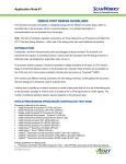
1.4.1
Connecting to SGDV-A11A SERVOPACK
Power supply
Three-phase 200 VAC
R S T
Molded-case
circuit breaker
(MCCB)
Protects the power supply
line by shutting the
circuit OFF when
overcurrent is
detected.
Noise filter
Used to eliminate
external noise from
the power line.
Magnetic
contactor
SGDV-A11A
SERVOPACK
Digital
operator
Turns the servo
ON and OFF.
Install a surge
absorber
(for lightning
surge).
Connect to the
MECHATROLINK-II
Connection cable
for digital operator
Personal
computer
Connection cable
for personal computer
I/O signal cable
Connect an external
regenerative resistor
to terminals B1 and B2
if the regenerative
capacity is insufficient.
When not using the safety function,
use the SERVOPACK with the safety
function jumper connector
(JZSP-CVH05-E, provided as an
accessory) inserted.
24-VDC brake power
supply
Used for a servomotor
with a brake.
Magnetic contactor
Battery case
(when an absolute
encoder is used.)
When using the safety function,
insert a connection cable specifically
for the safety function.
Turns the brake power supply
ON and OFF.
Install a surge absorber
(for lightning surge).
Outline
LED indicator or
external device
Regenerative
resistor *
1
Safety function
devices
Encoder cable
Motor main
circuit cable
SGMAV/SGMJV
Servomotor
∗
Remove the lead wire between the terminal B2 and B3 on the SERVOPACK before connecting an external regenerative resistor to the SERVOPACK.
1-7
1 Outline
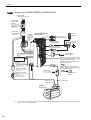
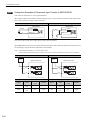
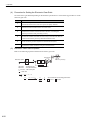
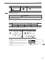
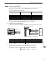
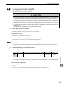
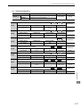
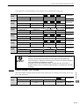
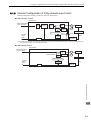
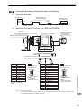
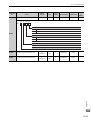
1.4.2 Connecting to SGDV-D11A SERVOPACK
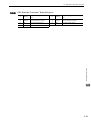
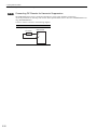
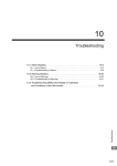
1.4.2
Connecting to SGDV-D11A SERVOPACK
Power supply
Three-phase 400 VAC
R ST
Molded-case
circuit breaker
(MCCB)
Protects the power
supply line by shutting
the circuit OFF when
overcurrent is
detected.
Noise filter
Used to eliminate
external noise from
the power line.
Magnetic
contactor
SGDV-D11A
SERVOPACK
Digital
operator
Turns the servo
ON and OFF.
Install a surge
absorber
(for lightning
surge).
Connect to the
MECHATROLINK-II
Personal
computer
Connection cable
for digital operator
Connection cable
for personal computer
I/O signal cable
LED indicator or
external device
Regenerative
resistor ∗2
When not using the safety function,
use the SERVOPACK with the safety
function jumper connector
(JZSP-CVH05-E, provided as an
accessory) inserted.
Brake power supply
When using the safety function,
insert a connection cable specifically
for the safety function.
DC Power
1
supply (24 VDC)
Connect an external
regenerative resistor
to terminals B1 and B2
if the regenerative
capacity is insufficient.
Used for a servomotor
with a brake.
Magnetic contactor
Battery case
(when an absolute
encoder is used.)
Turns the brake power supply
ON and OFF.
Install a surge absorber
(for lightning surge).
Motor main
circuit cable
Safety function
devices
Encoder cable
SGMGV
Servomotor
∗1. Use a 24 VDC power supply. (Must be prepared by the user.)
∗2. Remove the lead wire between the terminals B2 and B3 on the SERVOPACK before connecting an external regenerative resistor to the SERVOPACK.
1-8
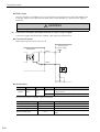
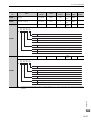
1.5 SERVOPACK Model Designation
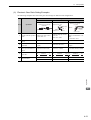
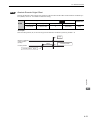
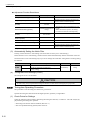
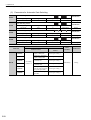
1.5
SERVOPACK Model Designation
Select the SERVOPACK according to the applied servomotor.
4th
digit
1st + 2nd +
3rd digits
5th + 6th
digits
7th
digit
11
A
SGDV – 2R8 A
SGDV
Series
Σ-V Series
8th to13th digits
7th digit: Design
Revision Order
8th to 13th digits: Option
Voltage Code
R70
200 V
400 V
Max. Allowable
Motor Capacity
50 W
R90
100 W
1R6
200 W
2R8
400 W
3R8
500 W
5R5
800 W
4th digit: Voltage
Code
Base-mounted type (standard)
001000
Rack-mounted type (option)
Voltage
A
200 V
D
400 V
5th + 6th digits: Interface Specifications
Code
1R9
500 W
3R5
1 kW
01
5R4
1.5 kW
11
8R4
2 kW
120
3 kW
170
5 kW
05
15
Analog voltage and pulse train
reference, rotational motor
MECHATROLINK-II communications
reference, rotational motor
Analog voltage and pulse train
reference, linear servomotor
MECHATROLINK-II communications
reference, linear servomotor
Outline
1st + 2nd + 3rd digits: Current
Blank
1
1-9
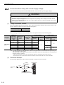
1 Outline
1.6
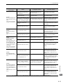
Inspection and Maintenance
This section describes the inspection and maintenance of SERVOPACK.
(1) SERVOPACK Inspection
For inspection and maintenance of the SERVOPACK, follow the inspection procedures in the following table
at least once every year. Other routine inspections are not required.
Item
Frequency
Procedure
Comments
Check for dust, dirt, and oil
Clean with compressed air.
on the surfaces.
Exterior
At least once a year
Loose Screws
Check for loose terminal
block and connector
screws.
Tighten any loose screws.
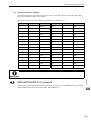
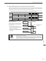
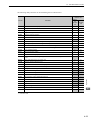
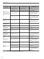
(2) SERVOPACK’s Parts Replacement Schedule
The following electric or electronic parts are subject to mechanical wear or deterioration over time. To avoid
failure, replace these parts at the frequency indicated.
Refer to the standard replacement period in the following table, contact your Yaskawa representative. After an
examination of the part in question, we will determine whether the parts should be replaced or not.
The parameters of any SERVOPACKs overhauled by Yaskawa are reset to the factory
settings before shipping. Be sure to confirm that the parameters are properly set before
starting operation.
.
Part
1-10
Standard Replacement
Period
Cooling Fan
4 to 5 years
Smoothing Capacitor
7 to 8 years
Relays
-
Fuses
10 years
Aluminum Electrolytic
Capacitor on Circuit Board
5 years
Operating Conditions
• Ambient Temperature: Annual average of 30°C
• Load Factor: 80% max.
• Operation Rate: 20 hours/day max.
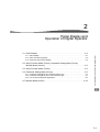
2
Panel Display and
Operation of Digital Operator
2.1.1 Status Display . . . . . . . . . . . . . . . . . . . . . . . . . . . . . . . . . . . . . . . . . . . . . . . . . . . . . . . 2-2
2.1.2 Alarm and Warning Display . . . . . . . . . . . . . . . . . . . . . . . . . . . . . . . . . . . . . . . . . . . . . 2-2
2.1.3 Mode Test without Motor Display . . . . . . . . . . . . . . . . . . . . . . . . . . . . . . . . . . . . . . . . 2-2
2.2 Utility Function Mode (Fnooo), Parameter Setting Mode (Pnooo),
Monitor Mode (Unooo) . . . . . . . . . . . . . . . . . . . . . . . . . . . . . . . . . . . . . . . 2-3
2.3 Utility Function Mode (Fnooo ) . . . . . . . . . . . . . . . . . . . . . . . . . . . . . . . . . 2-3
2.4 Parameter Setting Mode (Pnooo) . . . . . . . . . . . . . . . . . . . . . . . . . . . . . . . 2-5
2.4.1 Parameter Setting Mode for Parameter Setting Type . . . . . . . . . . . . . . . . . . . . . . . . . 2-5
2.4.2 Parameter Setting Mode for Function Selection Type . . . . . . . . . . . . . . . . . . . . . . . . . 2-7
2.4.3 How to Read a Parameter Explanation . . . . . . . . . . . . . . . . . . . . . . . . . . . . . . . . . . . . 2-8
2.5 Monitor Mode (Unooo) . . . . . . . . . . . . . . . . . . . . . . . . . . . . . . . . . . . . . . 2-10
Panel Display and Operation of Digital Operator
2.1 Panel Display . . . . . . . . . . . . . . . . . . . . . . . . . . . . . . . . . . . . . . . . . . . . . . 2-2
2
2-1
2 Panel Display and Operation of Digital Operator
2.1.1 Status Display
2.1
Panel Display
The servo status can be checked on the panel display of the SERVOPACK.
Also, if an alarm or warning occurs, its alarm or warning number is displayed.
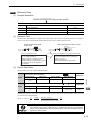
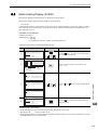
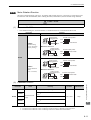
2.1.1
Status Display
The display shows the following status.
Display
Meaning
Baseblock
Light for baseblock. Does not light when servo is ON.
Rotation Detection (/TGON)
Light if motor speed exceeds the value set in Pn502. (Factory setting: 20 min-1)
Reference Input
Lights when a reference is being input.
CONNECT
Lights during connection.
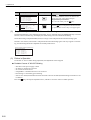
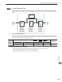
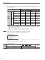
2.1.2
Alarm and Warning Display
If an alarm or warning occurs, the display will change in the following order.
Example: Alarm A.E60
Status
Display
2.1.3
Unlit
Unlit
Unlit
Unlit
Unlit
Mode Test without Motor Display
The display will change in the following order if a test is being done without a motor.
Status
Display
2-2
Unlit
Unlit
Unlit
Unlit
Unlit
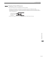
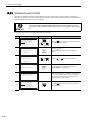
2.2 Utility Function Mode (Fn), Parameter Setting Mode (Pn), Monitor Mode (Un)
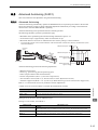
2.2
Utility Function Mode (Fn), Parameter Setting Mode
(Pn), Monitor Mode (Un)
Operation examples of Utility Function Mode (Fn), Parameter Setting Mode (Pn) and Monitor
Mode (Un) are in the following table.
For the Utility Function Mode, refer to 2.3 Utility Function Mode (Fn).
For the Parameter Setting Mode, refer to 2.4 Parameter Setting Mode (Pn).
For the Monitor Mode, refer to 2.5 Monitor Mode (Un).
Operations are performed with a digital operator or SigmaWin+.
The following procedures are described for cases in which the digital operator is used.
For more information on the usage of the digital operator, refer to AC servodrive Σ-V Series USER’S MANUAL Operation of Digital Operator (manual no.: SIEP S800000 55).
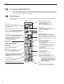
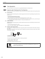
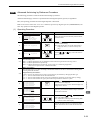
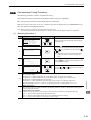
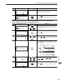
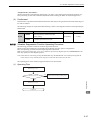
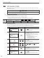
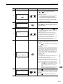
Utility Function Mode (Fn )
The setup and adjustment functions of the SERVOPACK are executed in this mode.
The digital operator displays numbers beginning with Fn.
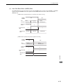
An operation example in Utility Function Mode is shown below for Origin Search (Fn003).
Step
Display after Operation
Keys
Description
1
㧮㧮 ̆㧲㨁㧺㧯㨀㧵㧻㧺̆
㧲㨚㧜㧜㧞
㧲㨚㧜㧜㧟
㧲㨚㧜㧜㧠
㧲㨚㧜㧜㧡
Open the Utility Function Mode main menu and select
Fn003.
2
㧮㧮 ̆㨆㧙㧿㨑㨍㨞㨏㨔̆
㨁㨚㧜㧜㧜㧩 㧜㧜㧜㧜㧜
㨁㨚㧜㧜㧞㧩 㧜㧜㧜㧜㧜
㨁㨚㧜㧜㧟㧩㧜㧜㧣㧣㧠
㨁㨚㧜㧜㧰㧩㧜㧜㧜㧜㧜㧜㧜㧜
Press the
Key.
The display is switched to the execution display of
Fn003.
If the display is not switched and "NO-OP" is displayed in the status display, change the following settings.
• If Write Prohibited is set:
→ Cancel the Write Prohibited setting.
• If the SV_ON signal is ON:
→ Turn ON the SV_OFF signal.
3
㧾㨁㧺 ̆㨆㧙㧿㨑㨍㨞㨏㨔̆
㨁㨚㧜㧜㧜㧩 㧜㧜㧜㧜㧜
㨁㨚㧜㧜㧞㧩 㧜㧜㧜㧜㧜
㨁㨚㧜㧜㧟㧩㧜㧜㧣㧣㧠
㨁㨚㧜㧜㧰㧩㧜㧜㧜㧜㧜㧜㧜㧜
Press the
Key.
"RUN" is displayed in the status display, and the servomotor becomes servo ON status.
Note: If the servomotor is already at the zero position,
"-Complete-" is displayed.
Panel Display and Operation of Digital Operator
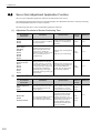
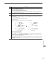
2.3
2
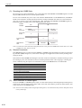
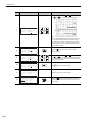
Pressing the
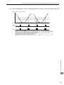
Key will rotate the motor in the forward direction. Pressing the
Key will rotate the
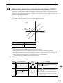
motor in the reverse direction. The rotation of the servomotor changes according to the setting of Pn000.0.
Parameter
4
㧾㨁㧺 ̆㧯㨛㨙㨜㨘㨑㨠㨑̆
㨁㨚㧜㧜㧜㧩 㧜㧜㧜㧜㧜
㨁㨚㧜㧜㧞㧩 㧜㧜㧜㧜㧜
㨁㨚㧜㧜㧟㧩㧜㧜㧜㧜㧜
㨁㨚㧜㧜㧰㧩㧜㧜㧜㧜㧝㧰㧡㧤
Pn000
key
(Forward)
key
(Reverse)
n.0
CCW
CW
n.1
CW
CCW
Note: Direction when viewed from the load of the servomotor.
Press the
or
Key until the motor stops. If the
origin search completed normally, "-Complete-" is displayed on the right top on the screen.
2-3
2 Panel Display and Operation of Digital Operator
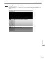
2-4
Step
Display after Operation
Keys
Description
5
㧮㧮 ̆㨆㧙㧿㨑㨍㨞㨏㨔̆
㨁㨚㧜㧜㧜㧩 㧜㧜㧜㧜㧜
㨁㨚㧜㧜㧞㧩 㧜㧜㧜㧜㧜
㨁㨚㧜㧜㧟㧩㧜㧜㧣㧣㧠
㨁㨚㧜㧜㧰㧩㧜㧜㧜㧜㧝㧰㧡㧤
When the origin search is completed, press the
Key.
"BB" is displayed in the status display, and the servomotor becomes servo OFF status. The display "-Complete-" changes to "-Z-Search-."
6
㧮㧮 ̆㧲㨁㧺㧯㨀㧵㧻㧺̆
㧲㨚㧜㧜㧞
㧲㨚㧜㧜㧟
㧲㨚㧜㧜㧠
㧲㨚㧜㧜㧡
Press the
Key.
The display returns to the Utility Function Mode main
menu.
This completes the operation.
2.4 Parameter Setting Mode (Pn)
2.4
Parameter Setting Mode (Pn)
Parameters related to the SERVOPACK are set in this mode.
The digital operator displays numbers beginning with Pn.
There are two types of parameters. One type requires value setting (parameter setting type) and the other
requires selecting the function allocated to each digit of the digital operator (function selection type).
The operation method differs between two types.
As for the operation method of parameter setting type, refer to 2.4.1.
As for the operation method of function selection type, refer to 2.4.2.
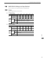
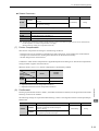
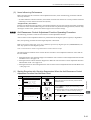
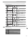
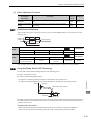
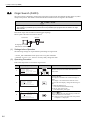
Parameter Setting Mode for Parameter Setting Type
The following example shows how to change the setting of parameter Pn304 (JOG speed) to 1000 min-1.
Step
Display after Operation
Keys
Description
1
㧮㧮ޓޓޓޓޓޓ㧙㧼㧾㧹㧛㧹㧻㧺㧙
㨁㨚㧜㧜㧜㧩ޓ㧜㧜㧜㧜㧜
㨁㨚㧜㧜㧞㧩ޓ㧜㧜㧜㧜㧜
㨁㨚㧜㧜㧤㧩ޓ㧜㧜㧜㧜㧜
㨁㨚㧜㧜㧰㧩㧜㧜㧜㧜㧜㧜㧜㧜
Press the
Mode.
Key to select the Parameter/Monitor
2
㧮㧮ޓޓޓޓޓޓ㧙㧼㧾㧹㧛㧹㧻㧺㧙
㨁㨚㧜㧜㧜㧩ޓ㧜㧜㧜㧜㧜
㨁㨚㧜㧜㧞㧩ޓ㧜㧜㧜㧜㧜
㨁㨚㧜㧜㧤㧩ޓ㧜㧜㧜㧜㧜
㨁㨚㧜㧜㧰㧩㧜㧜㧜㧜㧜㧜㧜㧜
Press the
or
Key to move the cursor to "Un."
3
㧮㧮ޓޓޓޓޓޓ㧙㧼㧾㧹㧛㧹㧻㧺㧙
㧼㨚㧜㧜㧜㧩㨚㧜㧜㧝㧜
㨁㨚㧜㧜㧞㧩ޓ㧜㧜㧜㧜㧜
㨁㨚㧜㧜㧤㧩ޓ㧜㧜㧜㧜㧜
㨁㨚㧜㧜㧰㧩㧜㧜㧜㧜㧜㧜㧜㧜
Press the
or
Key to change "Un" to "Pn."
4
㧮㧮ޓޓޓޓޓޓ㧙㧼㧾㧹㧛㧹㧻㧺㧙
㧼㨚㧜㧜㧜㧩㨚㧝㧜㧝㧝
㨁㨚㧜㧜㧞㧩ޓ㧜㧜㧜㧜㧜
㨁㨚㧜㧜㧤㧩ޓ㧜㧜㧜㧜㧜㨜㨡㨘㨟㨑
㨁㨚㧜㧜㧰㧩㧜㧜㧜㧜㧜㧜㧜㧜
Press the
Key to move the cursor to the column on
the right of "Pn."
5
㧮㧮ޓޓޓޓޓޓ㧙㧼㧾㧹㧛㧹㧻㧺㧙
㧼㨚㧟㧜㧠㧩㧜㧜㧡㧜㧜
㨁㨚㧜㧜㧞㧩ޓ㧜㧜㧜㧜㧜
㨁㨚㧜㧜㧤㧩ޓ㧜㧜㧜㧜㧜
㨁㨚㧜㧜㧰㧩㧜㧜㧜㧜㧜㧜㧜㧜
Press the arrow keys to display "Pn304".
To move the cursor to different columns:
Key
To change the settings:
,
Key
6
㧮㧮ޓޓޓޓޓޓ㧙㧼㧾㧹㧛㧹㧻㧺㧙
㧼㨚㧟㧜㧠㧩㧜㧜㧡㧜㧜
㨁㨚㧜㧜㧞㧩ޓ㧜㧜㧜㧜㧜
㨁㨚㧜㧜㧤㧩ޓ㧜㧜㧜㧜㧜
㨁㨚㧜㧜㧰㧩㧜㧜㧜㧜㧜㧜㧜㧜
Press the
Key to move the cursor to the one’s
place of Pn304.
7
㧮㧮ޓޓޓޓޓޓ㧙㧼㧾㧹㧛㧹㧻㧺㧙
㧼㨚㧟㧜㧠㧩㧜㧜㧡㧜㧜
㨁㨚㧜㧜㧞㧩ޓ㧜㧜㧜㧜㧜
㨁㨚㧜㧜㧤㧩ޓ㧜㧜㧜㧜㧜
㨁㨚㧜㧜㧰㧩㧜㧜㧜㧜㧜㧜㧜㧜
Press the
Key twice to move the cursor to the hundred’s place of Pn304.
8
㧮㧮ޓޓޓޓޓޓ㧙㧼㧾㧹㧛㧹㧻㧺㧙
㧼㨚㧟㧜㧠㧩㧜㧝㧜㧜㧜
㨁㨚㧜㧜㧞㧩ޓ㧜㧜㧜㧜㧜
㨁㨚㧜㧜㧤㧩ޓ㧜㧜㧜㧜㧜
㨁㨚㧜㧜㧰㧩㧜㧜㧜㧜㧜㧜㧜㧜
Press the
"1000."
,
Panel Display and Operation of Digital Operator
2.4.1
2
Key five times to change the setting to
2-5
2 Panel Display and Operation of Digital Operator
2.4.1 Parameter Setting Mode for Parameter Setting Type
2-6
Step
Display after Operation
9
㧮㧮ޓޓޓޓޓޓ㧙㧼㧾㧹㧛㧹㧻㧺㧙
㧼㨚㧟㧜㧠㧩㧜㧝㧜㧜㧜
㨁㨚㧜㧜㧞㧩ޓ㧜㧜㧜㧜㧜
㨁㨚㧜㧜㧤㧩ޓ㧜㧜㧜㧜㧜
㨁㨚㧜㧜㧰㧩㧜㧜㧜㧜㧜㧜㧜㧜
Keys
Description
Press the
Key to write the settings.
2.4 Parameter Setting Mode (Pn)
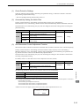
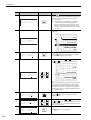
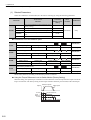
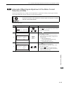
Parameter Setting Mode for Function Selection Type
The following example shows how to set the clear signal form (Pn200.1) of the position control reference
form selection switch (Pn200) to 0 "clearing position error pulse if the signal is at H level."
Step
Display after Operation
1
㧮㧮ޓޓޓޓޓޓ㧙㧼㧾㧹㧛㧹㧻㧺㧙
㨁㨚㧜㧜㧜㧩ޓ㧜㧜㧜㧜㧜
㨁㨚㧜㧜㧞㧩ޓ㧜㧜㧜㧜㧜
㨁㨚㧜㧜㧤㧩ޓ㧜㧜㧜㧜㧜
㨁㨚㧜㧜㧰㧩㧜㧜㧜㧜㧜㧜㧜㧜
Press the
Mode.
Key to select the Parameter/Monitor
2
㧮㧮ޓޓޓޓޓޓ㧙㧼㧾㧹㧛㧹㧻㧺㧙
㨁㨚㧜㧜㧜㧩ޓ㧜㧜㧜㧜㧜
㨁㨚㧜㧜㧞㧩ޓ㧜㧜㧜㧜㧜
㨁㨚㧜㧜㧤㧩ޓ㧜㧜㧜㧜㧜
㨁㨚㧜㧜㧰㧩㧜㧜㧜㧜㧜㧜㧜㧜
Press the
"Un."
or
Key to move the cursor to
3
㧮㧮ޓޓޓޓޓޓ㧙㧼㧾㧹㧛㧹㧻㧺㧙
㧼㨚㧜㧜㧜㧩㨚㧜㧜㧜㧜
㨁㨚㧜㧜㧞㧩ޓ㧜㧜㧜㧜㧜
㨁㨚㧜㧜㧤㧩ޓ㧜㧜㧜㧜㧜
㨁㨚㧜㧜㧰㧩㧜㧜㧜㧜㧜㧜㧜㧜
Press the
or
Key to change "Un" to "Pn."
4
㧮㧮ޓޓޓޓޓޓ㧙㧼㧾㧹㧛㧹㧻㧺㧙
㧼㨚㧜㧜㧜㧩㨚㧜㧜㧜㧜
㨁㨚㧜㧜㧞㧩ޓ㧜㧜㧜㧜㧜
㨁㨚㧜㧜㧤㧩ޓ㧜㧜㧜㧜㧜
㨁㨚㧜㧜㧰㧩㧜㧜㧜㧜㧜㧜㧜㧜
Press the
Key to move the cursor to the column
on the right of "Pn."
5
㧮㧮ޓޓޓޓޓޓ㧙㧼㧾㧹㧛㧹㧻㧺㧙
㧼㨚㧞㧜㧜㧩㨚㧜㧜㧜㧜
㨁㨚㧜㧜㧞㧩ޓ㧜㧜㧜㧜㧜
㨁㨚㧜㧜㧤㧩ޓ㧜㧜㧜㧜㧜
㨁㨚㧜㧜㧰㧩㧜㧜㧜㧜㧜㧜㧜㧜
Press the
Key twice to display "Pn200."
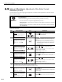
6
㧮㧮ޓޓޓޓޓޓ㧙㧼㧾㧹㧛㧹㧻㧺㧙
㧼㨚㧞㧜㧜㧩㨚㧜㧜㧜㧜
㨁㨚㧜㧜㧞㧩ޓ㧜㧜㧜㧜㧜
㨁㨚㧜㧜㧤㧩ޓ㧜㧜㧜㧜㧜
㨁㨚㧜㧜㧰㧩㧜㧜㧜㧜㧜㧜㧜㧜
Press the
Key to move the cursor to "Pn200.0."
7
㧮㧮ޓޓޓޓޓޓ㧙㧼㧾㧹㧛㧹㧻㧺㧙
㧼㨚㧞㧜㧜㧩㨚㧜㧜㧜㧜
㨁㨚㧜㧜㧞㧩ޓ㧜㧜㧜㧜㧜
㨁㨚㧜㧜㧤㧩ޓ㧜㧜㧜㧜㧜
㨁㨚㧜㧜㧰㧩㧜㧜㧜㧜㧜㧜㧜㧜
Press the
Key to move the cursor to "Pn200.1."
8
㧮㧮ޓޓޓޓޓޓ㧙㧼㧾㧹㧛㧹㧻㧺㧙
㧚
㧼㨚㧞㧜㧜㧩㨚㧜㧜㧝㧜
㨁㨚㧜㧜㧞㧩ޓ㧜㧜㧜㧜㧜
㨁㨚㧜㧜㧤㧩ޓ㧜㧜㧜㧜㧜
㨁㨚㧜㧜㧰㧩㧜㧜㧜㧜㧜㧜㧜㧜
Press the
to "1."
Key to change the setting of "Pn200.1"
9
㧭 㧥㧠㧝ޓޓޓ㧙㧼㧾㧹㧛㧹㧻㧺㧙
㧚
㧼㨚㧞㧜㧜㧩㨚㧜㧜㧝㧜
㨁㨚㧜㧜㧞㧩ޓ㧜㧜㧜㧜㧜
㨁㨚㧜㧜㧤㧩ޓ㧜㧜㧜㧜㧜
㨁㨚㧜㧜㧰㧩㧜㧜㧜㧜㧜㧜㧜㧜
Press the
Key to write the settings. If the setting
of Pn200 is changed, the new setting must be validated. If not, the warning "A.941" will be displayed.
10
Keys
Description
Panel Display and Operation of Digital Operator
2.4.2
2
The new setting must be validated. After the setting has been validated, the status display showing the "A.941"
warning will change to "BB."
2-7
2 Panel Display and Operation of Digital Operator
2.4.3 How to Read a Parameter Explanation
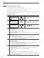
2.4.3
How to Read a Parameter Explanation
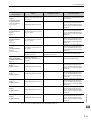
In this manual, each parameter is explained using the following example.
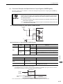
(1) Explanation Method for Parameter Setting Type
Control mode for which the parameter is
available
: Speed control and
internally set speed control
Position : Position control
Speed
Torque
Emergency Stop Torque
Pn406
: Torque control
Speed
Position
Torque
Setting Range
Setting Unit
Factory Setting
When Enabled
Classification
0 to 800%
1%
800%
After restart
Setup
Indicates setting range
for the parameter.
The range is decided
so that the maximum
value can be set even
in combination with a
servomotor with
different specifications.
Indicates minimum
setting unit for the
parameter.
Indicates parameter
value before shipment
(Factory setting).
Indicates if the power
has to be turned OFF
and ON again to
validate setting
changes.
"After restart"
indicates the change
will be effective after
turning OFF the power
and ON again, or
resetting software
(Fn030).
"Setup" indicates the
parameter used for basic
setting for operation.
"Tuning" indicates the
parameter used for tuning
of servo performance.
Note: The parameters classified as "tuning" are
not displayed at shipment. For displaying
the tuning parameters,
refer to
to (3)
(3)Explanation
Explanation
refer
Method for
forTuning
Tuning
Method
Parameters.
Parameters.
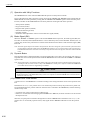
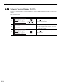
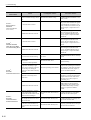
(2) Explanation Method for Function Selection Type
Parameter
Pn50A
Meaning
n.2 Input the forward run prohibited signal (P-OT) from
CN1-42 (Factory setting).
n.8 Forward run prohibited signal (P-OT) is disabled
(Forward rotation allowed).
The number of the
parameter
2-8
This blank shows the setting
value of the function selection,
as well as the status condition
on the panel operator and the
digital operator (JUSP-OP05A).
When Enabled
Classification
After restart
Setup
This section explains the
details of the function selection.
2.4 Parameter Setting Mode (Pn)
(3) Explanation Method for Tuning Parameters
Only setup parameters are displayed at shipment. To display tuning parameters, change the following parameter.
Application Function Selection Switch B
Parameter
Pn00B
Contents
When Enabled Classification
n.0
Displays only setup parameters. (Factory setting)
n.1
Displays all parameters. (Only user level 1)
Classification
Meaning
After restart
Display Method
Setup
Setting Method
Setup
Parameters
Parameters needed for setup
Tuning
Parameters
Parameters needed for tuning of
Displayed by setting Pn00B.0.
servo gain
Displayed with factory setting
Sets parameter individually.
Can set parameter using utility
function without regarding
parameter number.
Function selection switch (Pn000 to Pn080)
Application function for gain select switch
(Pn10B, Pn170)
Encoder (Pn205, Pn20A, Pn22A)
Electronic gear ratio (Pn20E, Pn210)
Encoder output (Pn212, Pn281)
JOG speed (Pn304)
Soft start (Pn305, Pn306)
Vibration detection switch (Pn310)
Tuning (Pn324, Pn560, Pn561)
Torque limit (Pn402 to Pn405)
Emergency stop force (Pn406)
Speed limit during torque control (Pn407)
Torque limit related switch (Pn408)
SEMI-F47 (Pn424, Pn425)
Zero clamp level (Pn501)
Rotation detection level (Pn502)
Speed coincidence signal output width
(Pn503)
Brake (Pn506 to Pn508)
Instantaneous power cut hold time (Pn509)
Input/output signal selection (Pn50A,
Pn50B, Pn50E, Pn50F, Pn510 to Pn512)
Excessive error level between servomotor
and load positions (Pn51B)
Excessive position error (Pn51E to Pn520,
Pn526 to Pn529, Pn584)
Positioning completed signal (Pn522,
Pn524)
Overload (Pn52B, Pn52C)
Monitor display at power ON (Pn52F)
Program JOG (Pn530 to Pn536)
Analog monitor (Pn550 to Pn553)
Regenerative resistor capacity (Pn600)
Position integral time constant (Pn11F)
Friction compensation (Pn121 to Pn125)
Gain switching (Pn131 to Pn139)
Current gain level (Pn13D)
Model following control (Pn140 to Pn14B)
Anti-resonance control (Pn160 to Pn165)
Vibration detection (Pn311 to Pn312)
Torque reference filter (Pn401, Pn40F,
Pn410, Pn412)
Notch filter (Pn409 to Pn40E)
EasyFFT (Pn456)
Tuning (Pn460)
Polarity detection (Pn481 to Pn482, Pn486
to Pn498)
Fully-closed control (Pn52A)
About 120 parameters
[Main Tuning Parameters]
Speed loop gain (Pn100, Pn104)
Speed loop integral time constant (Pn101,
Pn105)
Position loop gain (Pn102, Pn106)
Moment of inertia ratio (Pn103)
Feed forward (Pn109 to Pn10A)
Mode switch (Pn10C to Pn10F)
Panel Display and Operation of Digital Operator
[Main Setup Parameters]
2
About 70 parameters
2-9
2 Panel Display and Operation of Digital Operator
2.5
Monitor Mode (Un)
The monitor mode can be used for monitoring the reference values, I/O signal status, and SERVOPACK internal status.
The digital operator display numbers beginning with Un.
The following four settings are the factory settings.
㧮㧮ޓޓޓޓޓޓ㧙㧼㧾㧹㧛㧹㧻㧺㧙
㨁㨚㧜㧜㧜㧩ޓ㧜㧜㧜㧜㧜
㨁㨚㧜㧜㧞㧩ޓ㧜㧜㧜㧜㧜
㨁㨚㧜㧜㧤㧩ޓ㧜㧜㧜㧜㧜
㨁㨚㧜㧜㧰㧩㧜㧜㧜㧜㧜㧜㧜㧜
2-10
Shows the setting of Un000 (motor speed) as 0 min-1.
3
Wiring and Connection
3.1 Main Circuit Wiring . . . . . . . . . . . . . . . . . . . . . . . . . . . . . . . . . . . . . . . . . . 3-2
3.1.1
3.1.2
3.1.3
3.1.4
3.1.5
3.1.6
3.1.7
3.1.8
Names and Functions of Main Circuit Terminals . . . . . . . . . . . . . . . . . . . . . . . . . . . . . 3-2
SERVOPACK Main Circuit Wire Size . . . . . . . . . . . . . . . . . . . . . . . . . . . . . . . . . . . . . 3-3
Typical Main Circuit Wiring Examples . . . . . . . . . . . . . . . . . . . . . . . . . . . . . . . . . . . . . 3-5
General Precautions for Wiring . . . . . . . . . . . . . . . . . . . . . . . . . . . . . . . . . . . . . . . . . . 3-6
Precautions When Using the SERVOPACK with a DC Power Input . . . . . . . . . . . . . . 3-7
Precautions When Using More Than One SERVOPACK . . . . . . . . . . . . . . . . . . . . . . 3-9
Precautions When Using 400 V Power Supply Voltage . . . . . . . . . . . . . . . . . . . . . . 3-10
Designing a Power ON Sequence . . . . . . . . . . . . . . . . . . . . . . . . . . . . . . . . . . . . . . 3-11
3.2.1
3.2.2
3.2.3
3.2.4
3.2.5
I/O Signal (CN1) Names and Functions . . . . . . . . . . . . . . . . . . . . . . . . . . . . . . . . . . 3-12
I/O Signal Connector (CN1) Terminal Layout . . . . . . . . . . . . . . . . . . . . . . . . . . . . . . 3-13
Safety Function Signal (CN8) Names and Functions . . . . . . . . . . . . . . . . . . . . . . . . 3-14
Safety Function Signal (CN8) Terminal Layout . . . . . . . . . . . . . . . . . . . . . . . . . . . . . 3-14
Example of I/O Signal Connections . . . . . . . . . . . . . . . . . . . . . . . . . . . . . . . . . . . . . 3-15
3.3 I/O Signal Allocation . . . . . . . . . . . . . . . . . . . . . . . . . . . . . . . . . . . . . . . . 3-16
3.3.1 Input Signal Allocation . . . . . . . . . . . . . . . . . . . . . . . . . . . . . . . . . . . . . . . . . . . . . . . . 3-16
3.3.2 Output Signal Allocation . . . . . . . . . . . . . . . . . . . . . . . . . . . . . . . . . . . . . . . . . . . . . . 3-17
3.4 Examples of Connection to Host Controller . . . . . . . . . . . . . . . . . . . . . . 3-19
3.4.1 Connection Examples of Input Circuits to SERVOPACK . . . . . . . . . . . . . . . . . . . . . 3-19
3.4.2 Connection Examples of Sequence Input Circuits to SERVOPACK . . . . . . . . . . . . . 3-20
3.4.3 Connection Examples of Output Circuits to SERVOPACK . . . . . . . . . . . . . . . . . . . . 3-21
Wiring and Connection
3.2 I/O Signal Connections . . . . . . . . . . . . . . . . . . . . . . . . . . . . . . . . . . . . . . 3-12
3
3.5 Wiring MECHATROLINK-II Communications . . . . . . . . . . . . . . . . . . . . . 3-23
3.6 Examples of Encoder Connection . . . . . . . . . . . . . . . . . . . . . . . . . . . . . . 3-24
3.6.1 Connection Example of an Encoder . . . . . . . . . . . . . . . . . . . . . . . . . . . . . . . . . . . . . 3-24
3.6.2 CN2 Encoder Connector Terminal Layout . . . . . . . . . . . . . . . . . . . . . . . . . . . . . . . . . 3-25
3.7 Connecting Regenerative Resistors . . . . . . . . . . . . . . . . . . . . . . . . . . . . 3-26
3.7.1 Connecting Regenerative Resistors . . . . . . . . . . . . . . . . . . . . . . . . . . . . . . . . . . . . . 3-26
3.7.2 Setting Regenerative Registor Capacity . . . . . . . . . . . . . . . . . . . . . . . . . . . . . . . . . . 3-27
3.8 Noise Control and Measures for Harmonic Suppression . . . . . . . . . . . . 3-28
3.8.1 Wiring for Noise Control . . . . . . . . . . . . . . . . . . . . . . . . . . . . . . . . . . . . . . . . . . . . . . 3-28
3.8.2 Precautions on Connecting Noise Filter . . . . . . . . . . . . . . . . . . . . . . . . . . . . . . . . . . 3-30
3.8.3 Connecting DC Reactor for Harmonic Suppression . . . . . . . . . . . . . . . . . . . . . . . . . 3-32
3-1
3 Wiring and Connection
3.1.1 Names and Functions of Main Circuit Terminals
3.1
Main Circuit Wiring
The names, specifications, and functions of the main circuit terminals are given below.
Also this section describes the general precautions for wiring and precautions under special environments.
3.1.1
Names and Functions of Main Circuit Terminals
Names, functions and specifications are shown in the following table.
: Main terminals
Terminal
Symbols
L1, L2, L3
L1C, L2C
24 V, 0 V
B1/
Name
Main circuit input
terminals
Control power input
terminals
, B2, B3
Model SGDV-
R70A, R90A, 1R6A, 2R8A,
3R8A, 5R5A
Three-phase 200 to 230 V, +10%,
-15% (50/60 Hz)
1R9D, 3R5D, 5R4D, 8R4D,
120D, 170D
Three-phase 380 to 480 V, +10%,
-15% (50/60 Hz)
R70A, R90A, 1R6A, 2R8A,
3R8A, 5R5A
Single-phase 200 to 230 V, +10%,
-15% (50/60 Hz)
1R9D, 3R5D, 5R4D, 8R4D,
120D, 170D
24 VDC, ±15%
R70A, R90A, 1R6A, 2R8A
If the regenerative capacity is insufficient, connect an external regenerative
resistor (option) between B1/ and B2.
3R8A, 5R5A, 1R9D, 3R5D,
5R4D, 8R4D, 120D, 170D
Normally short B2 and B3.
If the internal regenerative resistor is
insufficient, remove the wire between B2
and B3 and connect an external regenerative resistor between B1/ and B2.
A
D
Normally short 1 and 2.
If a countermeasure against power supply
harmonic waves is needed, connect a DC
reactor between 1 and 2.
External regenerative
resistor terminals
B1, B2, B3
1,
3-2
2
DC reactor
connection terminal
for power supply
harmonic
suppression
Description
3.1 Main Circuit Wiring
Terminal
Symbols
B1/
or B1
or
2
U, V, W
Model SGDV-
Description
Main circuit plus
terminal
A
D
Main circuit minus
terminal
A
D
Servomotor
connection terminals
Use for connecting to the servomotor.
Ground terminals
(× 2)
Use for connecting the power supply ground terminal and servomotor
ground terminal.
Use when DC power supply input is used.
SERVOPACK Main Circuit Wire Size
This section describes the SERVOPACK Main Circuit Wire Size.
1. Wire sizes are selected for three cables per bundle at 40°C ambient temperature with
the rated current.
2. Use a cable with a minimum withstand voltage of 600 V for the main circuit.
3. If cables are bundled in PVC or metal ducts, take into account the reduction of the
allowable current.
4. Use a heat-resistant cable under high ambient or panel temperatures, where normal
vinyl cables will rapidly deteriorate.
Wiring and Connection
3.1.2
Name
3
3-3
3 Wiring and Connection
3.1.2 SERVOPACK Main Circuit Wire Size
(1) Cable Types
Use the following type of cable for main circuit.
Cable Type
Symbol
Allowable Conductor
Temperature
°C
Name
PVC
Normal vinyl cable
-
IV
600 V vinyl cable
60
HIV
Heat resistant vinyl cable
75
The following table shows the wire sizes and allowable currents for three cables. Use cables with specifications equal to or
less than those shown in the table.
• 600 V Heat-resistant Vinyl Cable (HIV)
AWG Size
Nominal
Configuration
Cross Section
(Number of
Diameter
2)
Wires/mm
(mm2)
Conductive
Resistance
(Ω/km)
Allowable Current at Ambient Temperature
(A)
30°C
40°C
50°C
20
0.5
19/0.18
39.5
6.6
5.6
4.5
19
0.75
30/0.18
26.0
8.8
7.0
5.5
18
0.9
37/0.18
24.4
9.0
7.7
6.0
16
1.25
50/0.18
15.6
12.0
11.0
8.5
14
2.0
7/0.6
9.53
23
20
16
12
3.5
7/0.8
5.41
33
29
24
10
5.5
7/1.0
3.47
43
38
31
8
8.0
7/1.2
2.41
55
49
40
6
14.0
7/1.6
1.35
79
70
57
Note: The values in the table are for reference only.
(2) Three-phase, 200 V
External Terminal Name
Terminal
Symbols
Main circuit power input
terminals
L1, L2, L3
Control power input terminals
L1C, L2C
Servomotor connection
terminals
External regenerative resistor
connection terminals
SERVOPACK Model SGDVR70A
1R6A
2R8A
HIV1.25
3R8A
5R5A
HIV2.0
HIV1.25
U, V, W
B1/
R90A
HIV1.25
HIV2.0
HIV1.25
, B2
Ground terminal
HIV2.0 or higher
(3) Three-phase, 400 V
External Terminal Name
Main circuit power input
terminals
L1, L2, L3
Control power input terminals
24 V, 0 V
Servomotor connection
terminals
U, V, W
External regenerative resistor
connection terminals
Ground terminal
3-4
Terminal
Symbols
B1/
, B2
SERVOPACK Model SGDV1R9D
3R5D
5R4D
8R4D
HIV1.25
120D
170D
HIV2.0
HIV3.5
HIV2.0
HIV3.5
HIV1.25
HIV1.25
HIV1.25
HIV2.0 or higher
HIV2.0
3.1 Main Circuit Wiring
3.1.3
Typical Main Circuit Wiring Examples
This section describes the typical main circuit wiring examples.
WARNING
• Do not touch the power terminals for five minutes after turning OFF the power. High voltage may still
remain in the SERVOPACK. When the voltage is discharged, the charge indicator will turn OFF. Make
sure the charge indicator is OFF before starting wiring or inspections.
Three-phase 200 V, SGDV-R70A, -R90A, -1R6A, -2R8A, -3R8A, -5R5A
R S T
SERVOPACK
SGDV-A
1QF
2SA
FIL
L1C
L2C
1KM
(For servo alarm display)
1RY
1PL
Main power Main power
supply OFF supply ON
1RY 1KM
1KM
U
V
W
M
L1
L2
L3
B2
CN1
B3 ALM+ 3
1
2
ALM− 4
Enc
+24V
1RY
1D
0 24V
1SA
1QF: Molded-case circuit breaker
FIL: Noise filter
1KM: Magnetic contactor
1RY: Relay
1PL: Indicator lamp
1SA: Surge absorber (for switching surge)
1D: Flywheel diode
2SA: Surge absorber (for lightning surge)
1QF
R S T
Wiring and Connection
Three-phase 400 V, SGDV-1R9D, -3R5D, -5R4D, -8R4D, -120D, -170D
SERVOPACK
SGDV-D
DC power supply
(24VDC)
−
+
2SA
FIL
24V
0V
1KM
(For servo
1RY alarm display)
Main
Main
power supply power supply
OFF
ON
1KM
1PL
1RY 1KM
U
V
W
L1
L2
L3
B2
B3 ALM+
1
2
ALM−
M
3
Enc
CN1
3
4
+24V
1RY
1D
0 24V
1SA
1QF: Molded-case circuit breaker
FIL: Noise filter
1KM: Magnetic contactor
1RY: Relay
1PL: Indicator lamp
1SA: Surge absorber (for switching surge)
1D: Flywheel diode
2SA: Surge absorber (for lightning surge)
3-5
3 Wiring and Connection
3.1.4 General Precautions for Wiring
3.1.4
General Precautions for Wiring
Use a molded-case circuit breaker (QF) or fuse to protect the power line.
• The SERVOPACK connects directly to a commercial power supply; it is not isolated
through a transformer or other device.
Always use a molded-case circuit breaker (QF) or fuse to protect the servo system
from accidents involving different power system voltages or other accidents.
• Install an earth leakage breaker.
The SERVOPACK does not have a built-in protective circuit for grounding.
• To configure a safer system, install a ground fault detector against overloads and
short-circuiting, or install a ground fault detector combined with a molded-case circuit
breaker.
Do not turn power ON and OFF frequently. Do not turn power ON or OFF more than
once per minute.
• The power supply in the SERVOPACK contains a capacitor, which causes a high
charging current to flow when power is turned ON. Frequently turning power ON and
OFF will causes the main circuit elements in the SERVOPACK to deteriorate.
To ensure safe, stable application of the servo system, observe the following precautions when wiring.
Use the connecting cables specified in the Σ-V Series SGMV/SGDV Catalog (KAEPS80000042).
Design and arrange the system so that each cable will be as short as possible.
Observe the following precautions when wiring the main circuit.
• Use shielded twisted-pair wires or shielded multi-core twisted-pair wires for signal lines and encoder lines.
• The maximum wiring length is 3 m for signal lines and 50 m for encoder lines.
Observe the following precautions when wiring the ground.
• Use a cable as thick as possible (at least 2.0 mm2)
• Grounding to a resistance of 100Ω or less is recommended. For 400 VAC SERVOPACKs, a grounding
resistance of 10Ω or less is recommended.
• Be sure to ground at only one point.
• Ground the servomotor directly if the servomotor is insulated from the machine.
The signal cable conductors are as thin as 0.2 mm or 0.3 mm. Do not impose excessive bending
force or tension.
3-6
3.1 Main Circuit Wiring
3.1.5
Precautions When Using the SERVOPACK with a DC Power Input
When using the SERVOPACK with a DC power input, set parameter Pn001.2 to 1, and pay attention to the
following items.
WARNING
• Either AC or DC power can be input to the 200 V, 400 V SERVOPACKs.
Always set Pn001.2 to 1 to specify a DC power input before inputting DC power.
If DC power is input without changing the parameter setting, the SERVOPACK’s internal elements will burn and
may cause fire or equipment damage.
• With a DC power input, time is required to discharge electricity after the main power supply is turned OFF.
A high residual voltage may remain in the SERVOPACK after the power supply is turned OFF. Be careful
not to get an electric shock.
• Install fuses on the wires if DC power is used.
(1) DC Power Supply Input Terminals for the Main and Control Circuits
Three-phase, 200 V
Terminal Name and Description
SERVOPACK model
SGDV
-R70A, -R90A, -1R6A,
-2R8A, -3R8A, -5R5A
Main circuit plus terminal
Main circuit minus
terminal
Control power supply
input terminal
270 V to 320 VDC
0 VDC
270 V to 320 VDC
(No polarity)
200 V to 230 VAC
B1/
2
L1C, L2C
Three-phase, 400 V
SERVOPACK model
SGDV
-1R9D, -3R5D, -5R4D,
-8R4D,-120D
-170D
Main circuit plus terminal
Main circuit minus
terminal
Control power supply
input terminal
513 V to 648 VDC
0 VDC
24VDC (± 15%)
B1/
2
24 V, 0 V
2
24 V, 0 V
Wiring and Connection
Terminal Name and Description
3
3-7
3 Wiring and Connection
3.1.5 Precautions When Using the SERVOPACK with a DC Power Input
(2) Wiring Example with DC Power Supply Input
200 V SERVOPACK SGDV-A
R S T
1QF
SERVOPACK
SGDV-A
2SA
FIL
FIL
M
B1/
AC/DC
2
Enc
L1C
(For servo
1RY alarm display)
L2C
1PL
Main power Main power
supply OFF supply ON
1RY
ALM− 4
1D
1RY 1KM
1KM
+24V
CN1
ALM+ 3
024V
1SA
1QF: Molded-case circuit breaker
FIL: Noise filter
1KM: Magnetic contactor
1RY: Relay
1PL: Indicator lamp
1SA: Surge absorber (for switching surge)
1D: Flywheel diode
2SA: Surge absorber (for lightning surge)
400 V SERVOPACK SGDV-D
R S T
1QF
SERVOPACK
SGDV-D
2SA
FIL
FIL
U
V
W
1FU
B1
AC/DC
AC/DC
M
M
2
Enc
24 V
AC/DC
AC/DC
1RY
0V
Main power Main power
supply OFF supply ON
1PL
+24V
CN1
ALM+ 3
1RY
ALM− 4
1D
1RY 1KM
1KM
1QF: Molded-case circuit breaker
FIL: Noise filter
1KM: Magnetic contactor
1RY: Relay
∗
0 V
1SA
1PL: Indicator lamp
1SA: Surge absorber (for switching surge)
1D: Flywheel diode
2SA: Surge absorber (for lightning surge)
Terminal names differ from model of SERVOPACK. Refer to (1) DC Power Supply Input Terminals for the Main and Control Circuits.
Note: The SERVOPACK that can use a DC power supply is not capable of processing the regenerated energy. Provide
measures to process the regenerated energy on the power supply.
(3) Parameter Setting
When using a DC power supply, make sure to set the parameter Pn001.2 to "1" (DC power input supported)
before inputting DC power.
Parameter
Pn001
3-8
Meaning
n.0
AC power input supported
n.1
DC power input supported
When Enabled Classification
After restart
Setup
3.1 Main Circuit Wiring
3.1.6
Precautions When Using More Than One SERVOPACK
This section shows an example of the wiring when more than one SERVOPACK is used and the precautions.
(1) Wiring Example
Connect the alarm output (ALM) terminals for the three SERVOPACKs in series to enable alarm detection
relay 1RY to operate.
When the alarm occurs, the ALM output signal transistor is turned OFF.
Power supply
R S T
Power
OFF
1QF
Power
ON
1RY
2SA
1KM
1KM
FIL
1SA
1KM
L1
L2
L3
Relay
terminal
Relay
terminal
SERVOPACK
Servomotor
M
L1C
L2C
1RY
CN1
3 ALM+
4
L1
L2
L3
Relay
terminal
Relay
terminal
ALM -
SERVOPACK
Servomotor
M
L1C
L2C
CN1
3 ALM+
1QF: Molded-case circuit breaker
FIL: Noise filter
1KM: Magnetic contactor
1RY: Relay
1PL: Indicator lamp
1SA: Surge absorber (for switching surge)
1D: Flywheel diode
2SA: Surge absorber (for lightning surge)
4
L1
L2
L3
ALM -
SERVOPACK
Servomotor
Wiring and Connection
+24V
3
M
L1C
L2C
CN1
3 ALM+
4
ALM -
0V
(2) Precautions
Multiple servos can share a single molded-case circuit breaker (QF) or noise filter. Always select a QF or
noise filter that has enough capacity for the total power capacity (load conditions) of those servos.
3-9
3 Wiring and Connection
3.1.7 Precautions When Using 400 V Power Supply Voltage
3.1.7
Precautions When Using 400 V Power Supply Voltage
This section shows the precautions when SERVOPACK is used with 400 V power supply voltage.
WARNING
• Do not connect the SERVOPACK for 200 V directly to a voltage of 400 V.
The SERVOPACK will be destroyed.
• Control the AC power supply ON and OFF sequence at the primary side of voltage conversion transfer.
Voltage conversion transfer inductance will cause a surge voltage if the power is turned ON and OFF at the secondary, damaging the SERVOPACK.
(1) Voltage Conversion Transfer
When using SERVOPACK for three-phase 200 V with the three-phase 400 VAC class (380 V to 480 V), prepare the following voltage conversion transfers (three-phase).
Primary Voltage
380 to 480 VAC
Secondary Voltage
200 VAC
When selecting a voltage conversion transfer, refer to the capacities shown in the following table.
Main Power
Supply
Three-phase
200 V
Maximum
Applicable
Servomotor
Capacity
[kW]
SERVOPACK
Model
SGDV-
Current Capacity
Voltage
Capacity per
SERVOPACK
[kVA]
Main Circuit
[Arms]
0.05
R70A
0.2
1.0
0.1
R90A
0.3
1.0
0.2
1R6A
0.6
2.0
0.4
2R8A
1
3.0
0.5
3R8A
0.9
3.0
0.75
5R5A
1.6
6.0
Control
Circuit
[Arms]
Inrush Current
Main Circuit
[A0-p]
33
0.2
Control
Circuit
[A0-p]
70
33
33
33
Note: To comply with the Low Voltage Directive, connect a UL-approved fuse or circuit breaker to the input side to provide protection from short-circuits.
The values of the current capacity and inrush current are nominal. Select a fuse and molded-case circuit breaker that
satisfy the following conditions.
• Main circuit and control circuit: Does not turn OFF within five seconds after the current is tripled.
• Inrush current: Does not turns OFF within 20 ms after the current reaches the value shown in the table.
(2) Connection Example
The following diagram shows the connection example of voltage conversion transfer.
Voltage
conversion
transfer
SERVOPACK
1 KM
L1
L2
L3
Three-phase
400 V
1KM
Magnetic contactor for
power supply ON and OFF
3-10
3.1 Main Circuit Wiring
Designing a Power ON Sequence
Note the following points when designing the power ON sequence.
• Design the power ON sequence so that main power is turned OFF when a servo alarm signal is output.
• The ALM signal is output for five seconds max. when the power is turned ON. Take this into consideration when
designing the power ON sequence. The ALM signal actuates the alarm detection relay 1Ry to stop main circuit power
supply to the SERVOPACK.
Control power supply
5.0 s max.
Servo alarm (ALM)
output signal
• Select the power supply specifications for the parts in accordance with the input power supply.
Wiring and Connection
3.1.8
3
3-11
3 Wiring and Connection
3.2.1 I/O Signal (CN1) Names and Functions
3.2
I/O Signal Connections
This section describes the names and functions of I/O signals (CN1). Also terminal layout and connection
examples by control method are shown.
3.2.1
I/O Signal (CN1) Names and Functions
The following table shows the names and functions of I/O signals (CN1).
(1) Input Signals
Signal
Pin No.
Name
Function
Reference
Section
/DEC
9
Homing deceleration
limit switch
Connects the deceleration limit switch for homing.
P-OT
N-OT
7
8
Forward run
prohibited,
Reverse run
prohibited
Overtravel prohibited: Stops servomotor when movable part
travels beyond the allowable range of motion.
/EXT 1
/EXT 2
/EXT 3
10
11
12
External latch signal 1
Connects the external signals that latch the current feedback
External latch signal 2
pulse counter.
External latch signal 3
+24VIN
6
Control power supply for sequence signal
BAT (+)
BAT (-)
21
22
Battery (+) input signal
Connecting pin for the absolute encoder backup battery.
Battery (−) input signal
−
/SIO
13
General-purpose
input signal
−
Control power supply input for sequence signals: Users must
provide the +24 V
power supply.
Allowable voltage fluctuation range: 11 to 25 V
General-purpose input signal:
Monitored in the I/O monitor field of MECHATROLINK-II.
−
4.3.2
−
3.4.2
Note 1. The functions allocated to /DEC, P-OT, N-OT, /EXT1, /EXT2, and /EXT3 input signals can be changed by using
the parameters. Refer to 3.3.1 Input Signal Allocation.
2. If the Forward run prohibited/ Reverse run prohibited function is used, the software can be used to stop the SERVOPACK. If the application does not satisfy the safety requirements, add an external circuit for safety reasons as
required.
(2) Output Signals
Signal
ALM+
ALM/BK+
(/SO1+)
/BK(/SO1-)
Pin No.
Name
Function
3
4
Servo alarm output
signal
Turns OFF when an error is detected.
−
1
Controls the brake. The brake is released when the signal
turns ON.
Brake interlock signal
Allocation can be changed to general-purpose output signals
(/SO1+, /SO1-).
4.3.3
2
/SO2+
/SO2/SO3+
/SO3-
23
24
25
26
General-purpose
output signal
Geneal-purpose output signal
Note: Set the parameter to allocate a function.
FG
16
Signal ground
Connected to frame ground if the shield wire of the I/O signal
cable is connectedto the connector shell.
Note: For more information on the allocation of /SO1, /SO2, and /SO3, refer to 3.3.2 Output Signal Allocation.
3-12
Reference
Section
−
3.2 I/O Signal Connections
I/O Signal Connector (CN1) Terminal Layout
The following table shows the terminal layout of I/O signal connectors
(CN1).
Brake interlock
1 /BK+
(/SO1+) output
3 ALM+
Servo alarm
output
/BK2 (/SO1-) Brake interlock
output
14 BAT(+)
16 SG
4 ALM5
Servo alarm
output
Control power
18 /PAO
6 +24VIN supply for sequence
7 P-OT
(/SI1)
9 /DEC
(/SI3)
/EXT2
11 (/SI5)
13 /SI0
Forward run
prohibited input
8 N-OT
(/SI2)
Zero-point return
deceleration
switch input
10 /EXT1
(/SI4)
External latch
signal 2 input
/EXT3
12 (/SI6)
General-purpose
input
signal input
20 /PBO
Reverse run
prohibited input
External latch
signal 1 input
External latch
signal 3 input
22 /PCO
24 /SO226 /SO3-
Battery (+)
input
15 BAT(-)
Signal ground
17
PG dividing
pulse (Phase-A)
output
19
PG dividing
pulse (Phase-B)
output
21
PG dividing
pulse (Phase-C)
output
23
General-purpose
input
25
General-purpose
input
PAO
PBO
PCO
Battery (-)
input
PG dividing
pulse (Phase-A)
output
PG dividing
pulse (Phase-B)
output
PG dividing
pulse (Phase-C)
output
/SO2+
General-purpose
input
/SO3+
General-purpose
input
Note 1. Do not use unused terminals.
2. Connect the shield of the I/O signal cable to the connector shell.
Connect to the FG (frame ground) at the SERVOPACK connector.
3. The functions allocated to the following input signals can be changed by using the parameters.
Input signals: /DEC, P-OT, N-OT, /EXT1, /EXT2, /EXT3
4. The output signals /SO1, /SO2, and /SO3 can be used as the output signal /COIN, /V-CMP, /TGON, /S-RDY,
/CLT, /VLT, /BK, /WARN, or /NEAR by setting the parameter Pn50E, Pn50F, or Pn510. For details, refer to 3.3.2
Output Signal Allocation.
Wiring and Connection
3.2.2
3
3-13
3 Wiring and Connection
3.2.3 Safety Function Signal (CN8) Names and Functions
3.2.3
Safety Function Signal (CN8) Names and Functions
The following table shows the names and functions of safety function signals (CN8).
Signal Name
3.2.4
Pin No.
/HWBB1+
4
/HWBB1-
3
/HWBB2+
6
/HWBB2-
5
EDM1+
8
EDM1-
7
Function
Hard wire baseblock input
Baseblock (motor current off) when OFF
Monitored circuit status output
ON when the hard wire baseblock function is normally activated.
Safety Function Signal (CN8) Terminal Layout
The following table shows the terminal layout of safety function signals (CN8).
Signal Name
Function
–
1
Unused terminal *
–
2
Unused terminal *
/HWBB1-
3
Hard wire baseblock input 1
/HWBB1+
4
Hard wire baseblock input 1
/HWBB2-
5
Hard wire baseblock input 2
/HWBB2+
6
Hard wire baseblock input 2
EDM1+
7
Monitored circuit status output 1
EDM1-
8
Monitored circuit status output 1
∗
3-14
Pin No.
Do not use unused terminals. (connected to the internal circuits)
3.2 I/O Signal Connections
Example of I/O Signal Connections
The following diagram shows a typical connection example.
Photocoupler output
Max. operating voltage:
30 VDC
Max. operating current:
50 mA DC
SGDV SERVOPACK
+24VIN
+24V
Forward run prohibited
(Prohibited when OFF)
P-OT
/SI1
Reverse run prohibited
(Prohibited when OFF)
N-OT
Homing deceleration
switch
(Decelerated when ON)
/DEC
Control power supply
for sequence signal ∗3.
External latch signal 1
(Latched when ON)
External latch signal 2
(Latched when ON)
External latch signal 3
(Latched when ON)
6
3.3kΩ
3 ALM+
7
1 SO1+ / BK+
/SI2
8
/SI3
9
Brake interlock
2 SO1- / BK- (Brake released when ON)
23 /SO2+
24 /SO225 /SO3+
/EXT1
/EXT2
/EXT3
/SI4
10
/SI5
11
/SI6
12
26 /SO317
Switch
Safety device ∗4
0V
fuse
PAO
18 /PAO
19 PBO
20 /PBO
21 PCO
22 /PCO
16 SG
Generalpurpose /SI0 13
∗2.
BAT+
14
∗3
Backup battery
BAT- 15
(2.8 to 4.5 V)
24V
Servo alarm output
(OFF for an alarm)
4 ALM-
Encoder output pulses
Applicable line receiver
SN75175 manufactured by
Texas Instruments or an MC3486
equivalent
Signal ground
∗1.
/HWBB1+
4
/HWBB1-
3
/HWBB2+
6
/HWBB2-
5
CN8
8
7
EDM1+
EDM1-
SERVOPACK
Connector
shell
FG Connect shield to
connector shell.
∗1.
represents twisted-pair wires.
∗2. Connect when using an absolute encoder. When the encoder cable for the battery case is connected, do not connect a
backup battery.
∗3. Customers must purchase a 24 VDC power supply with double-shielded enclosure.
∗4. For servo ON, connect to safety device and set wiring to enable safety function. When not using the safety function,
use the SERVOPACK with the plug (JZSP-CVH05-E, provided as an accessory) inserted into the CN8.
Note: The functions allocated to the input signals /DEC, P-OT, N-OT, /EXT1, /EXT2, and /EXT3 and the output signals
/SO1, /SO2, and /SO3 can be changed by using the parameters. Refer to 3.3.1 Input Signal Allocation and 3.3.2
Output Signal Allocation.
Wiring and Connection
3.2.5
3
3-15
3 Wiring and Connection
3.3.1 Input Signal Allocation
3.3
I/O Signal Allocation
This section describes the I/O signal allocation.
3.3.1
Input Signal Allocation
Input signals are allocated as shown in the following table.
means factory setting.
Signal Name
Validity
Level
CN1 Pin Numbers
Input
Signal
Parameter Setting
Allocation
Connection Not
required
(SERVOPACK
judges the
connection)
13
7
8
9
10
11
12
(SI0) (SI1) (SI2) (SI3) (SI4) (SI5) (SI6)
Forward Run Prohibited
Pn50A.3 setting
H
P-OT
0
1
2
3
4
5
6
L
/P-OT
9
A
B
C
D
E
F
Reverse Run
Prohibited
Pn50B.0 setting
H
N-OT
0
1
2
3
4
5
6
L
/N-OT
0
A
B
C
D
E
F
Forward External
Torque Limit
Pn50B.2 setting
L
/P-CL
0
1
2
3
4
5
6
H
P-CL
9
A
B
C
D
E
F
L
/N-CL
0
1
2
3
4
5
6
H
N-CL
9
A
B
C
D
E
F
Reserve External
Torque Limit
Pn50B.3 setting
Homing Deceleration
LS
Pn511.0 setting
L
/DEC
0
1
2
3
4
5
6
H
DEC
9
A
B
C
D
E
F
External Latch Signal 1
Pn511.1 setting
L
EXT1
*
*
*
*
4
5
6
H
/EXT1
*
*
*
*
D
E
F
External Latch Signal 2
Pn511.2 setting
L
EXT2
*
*
*
*
4
5
6
H
/EXT2
*
*
*
*
D
E
F
External Latch Signal 3
Pn511.3 setting
L
EXT3
*
*
*
*
4
5
6
H
/EXT3
*
*
*
*
D
E
F
∗
Always
ON
Always
OFF
7
8
7
8
7
8
7
8
7
8
7
8
7
8
7
8
Always set to "Invalid."
1. When using Forward Run Prohibited, and Reverse Run Prohibited signals with the
setting "Polarity Reversal," the machine may not move to the specified safe direction
at occurrence of failure such as signal line disconnection. If such setting is absolutely
necessary, confirm the operation and observe safety precautions.
2. When two or more signals are allocated to the same input circuit, input signal level is
valid for all allocated signals.
3-16
3.3 I/O Signal Allocation
3.3.2
Output Signal Allocation
Output signals are allocated as shown in the following table.
means factory setting.
CN1 Pin No.
1/(2)
23/(24)
25/(26)
Signal Output Polarity Setting
Pn512.0 setting
0
Positioning
Completion
(/COIN)
Pn50E.0 setting
Speed Coincidence
Detection
(/V-CMP)
Pn50E.1 setting
Rotation Detection
(/TGON)
Pn50E.2 setting
0
Invalid
1
L
1
(Reverse)
Pn512.1 setting
0
1
(Reverse)
L
1
L
L
1
L
L
0
Invalid
1
L
L
Invalid
1
L
L
Invalid
1
L
L
Invalid
1
L
1
L
L
Invalid
1
L
2
3
L
H
L
H
L
H
H
2
0
H
H
H
3
Near
(/NEAR)
Pn510.0 setting
L
3
L
Invalid
H
H
2
0
L
H
3
Warning
(/WARN)
Pn50F.3 setting
H
H
2
0
L
H
3
Brake
(/BK)
Pn50F.2 setting
H
H
2
0
L
H
3
Speed Limit Detection
(/VLT)
Pn50F.1 setting
H
H
2
0
L
H
3
Torque Limit Detection
(/CLT)
Pn50F.0 setting
H
H
2
3
Servo Ready
(/S-RDY)
Pn50E.3 setting
L
L: Output signal is L level when the
parameter is valid.
H: Output signal is H level when the
parameter is valid.
Invalid: Not use the output signal.
H
3
Invalid
1
H
2
0
Remark
(Reverse)
H
3
Invalid
0
H
2
0
Pn512.2 setting
Wiring and Connection
Parameter Setting
Allocation
H
L
H
3-17
3 Wiring and Connection
3.3.2 Output Signal Allocation
• The signals not detected are considered as "Invalid."
• When two or more signals are allocated to the same output circuit, a signal is output
with OR logic circuit.
3-18
3.4 Examples of Connection to Host Controller
3.4
Examples of Connection to Host Controller
This section shows examples of SERVOPACK I/O signal connection to the host controller.
3.4.1
Connection Examples of Input Circuits to SERVOPACK
(1) Safety Input Circuit
As for wiring input signals for safety function, input signals make common 0 V. It is necessary to make an
input signal redundant.
Input Signal Connection Example
24 V power supply
Switch
SERVOPACK
/HWBB1+ 4
Fuse
/HWBB1- 3
/HWBB2+ 6
/HWBB2- 5
Wiring and Connection
0V
3
3-19
3 Wiring and Connection
3.4.2 Connection Examples of Sequence Input Circuits to SERVOPACK
3.4.2
Connection Examples of Sequence Input Circuits to SERVOPACK
CN1 connector terminals 6 to 13 are explained below.
The sequence input circuit interface connects through a relay or open-collector transistor circuit. Select a lowcurrent relay otherwise a faulty contact will result.
Relay Circuit Example
Open-collector Circuit Example
SERVOPACK
SERVOPACK
24 VDC
+24VIN 3.3 kΩ
24 VDC
+24 VIN 3.3 kΩ
/DEC, etc.
/DEC, etc.
Note: The 24 VDC external power supply capacity must be 50 mA minimum.
The SERVOPACK’s I/O circuit uses bidirectional photocoupler. Select either the sink circuit or the source circuit according to the specifications required for each machine.
Note:
• The connection examples in 3.2.5 show sink circuits.
• The ON/OFF polarity differs between when a sink circuit is connected and when a source circuit is connected.
Sink Circuit
Source Circuit
24 V
24 V
+
−
+
SERVOPACK input
Input Signal Polarities
3-20
SERVOPACK input
−
Input Signal Polarities
Signal
Level
Voltage
Level
Contact
Signal
Level
Voltage
Level
Contact
ON
Low (L)
level
0V
Close
ON
High (H)
level
24 V
Close
OFF
High (H)
level
24 V
Open
OFF
Low (L)
level
0V
Open
3.4 Examples of Connection to Host Controller
3.4.3
Connection Examples of Output Circuits to SERVOPACK
The following diagrams show examples of how output circuits can be connected the SERVOPACK.
(1) Photocoupler Output Circuit
Photocoupler output circuits are used for servo alarm (ALM), servo ready (/S-RDY), and other sequence output signal circuits. Connect a photocoupler output circuit through a relay or line receiver circuit.
Relay Circuit Example
Line Receiver Circuit Example
SERVOPACK
5 to 24 VDC
SERVOPACK
5 to 12 VDC
Relay
0V
Note: The maximum allowable voltage and current capacities for photocoupler output circuits are as follows.
• Voltage: 30 VDC
• Current: 5 to 50 mA DC
(2) Line Driver Output Circuit
CN1 connector terminals, 17-18 (phase-A signal), 19-20 (phase-B signal), and 21-22 (phase-C signal) are
explained below.
Encoder serial data converted to two-phase (phases A and B) pulse output signals (PAO, /PAO, PBO, /PBO)
and origin pulse signals (PCO, /PCO) are output via line-driver output circuits. Normally, the SERVOPACK
uses this output circuit in speed control to comprise the position control system at the host controller. Connect
the line-driver output circuit through a line receiver circuit at the host controller.
SERVOPACK
Photocoupler Circuit Example
Host Controller
Host Controller
SERVOPACK
Applicable line driver
SN75ALS174 or the
equivalent
Applicable line driver
SN75174 manufactured by
Texas Instruments or the
equivalent
220 to
470 Ω
Wiring and Connection
Line Receiver Circuit Example
3
(3) Safety Output Circuit
External device monitor (EDM1), an output signal of safety function, is explained below. EDM1 is a function
for monitoring a failure of HWBB function. Connect it to safety device as a feedback signal.
The relation between EDM1 and /HWBB1, /HWBB2 signals are explained below.
Signal Name
When both /HWBB1 and
/HWBB2 signals are OFF,
EDM1 signal turns ON.
Logic
/HWBB1
ON
ON
OFF
OFF
/HWBB2
ON
OFF
ON
OFF
EDM1
OFF
OFF
OFF
ON
3-21
3 Wiring and Connection
3.4.3 Connection Examples of Output Circuits to SERVOPACK
EDM1 Signal
Detection of failures in the EDM1 circuit can be checked using the following four status of the EDM1 signal
in the table. Failures can be detected if the failure status can be confirmed, e.g., when the power supply is
turned ON.
WARNING
The EDM1 signal is not a safety output. Use it only for monitoring a failure.
(4) Connection Example and Specifications of EDM1 Output Signal
Connection example and specifications of EDM1 output signal are explained below.
Connection Example
EDM1 output signal is used for source circuit.
External Device
24 V Power Supply
SERVOPACK
8
EDM1+
7
EDM1-
0V
Specifications
Type
Output
Signal Name
EDM1
Pin No.
CN9-8
CN9-7
Input Status
Meaning
ON
Both baseblocks by /HWBB1 signal and /HWBB2 signal
normally activate.
OFF
−
Electrical characteristics of EDM1 signal are as follows.
Items
Maximum Allowable Voltage
Maximum Current
3-22
Characteristic
Remarks
30 VDC
−
50 m ADC
−
Maximum Voltage Drop at ON
1.0 V
Voltage between EDM1+ to EDM1- at current is 50 mA.
Maximum Delay Time
20 ms
Time from change of /HWBB1, /HWBB2 to change of
EDM1
3.5 Wiring MECHATROLINK-II Communications
Wiring MECHATROLINK-II Communications
The following diagram shows an example of connections between a host controller and a SERVOPACK using
MECHATROLINK-II communications cables (CN6A, CN6B).
218IF-01
MP2300
YASKAWA
RDY
RUN
RUN
ERR
ALM
TX
ERR
BAT
STRX
COL
STOP
SUP
INT
CNFG
MON
TEST
TX
RX
INIT
TEST
OFF
ޓ
ON
SW1
OFFޓON
PORT
BATTERY
Option
M-I/II
Option
CPUޓ
I/O
DC24V
DC 0V
10Base-T
L1
L2
Ln
Terminator
Note 1. The length of the cable between stations (L1, L2 ... Ln) must be 0.5 m or more.
2. The total cable length must be L1 + L2 ... + Ln ≤ 50.
3. When multiple SERVOPACKs are connected by MECHATROLINK-II communications cable, a terminator must
be installed at the final SERVOPACK.
Wiring and Connection
3.5
3
3-23
3 Wiring and Connection
3.6.1 Connection Example of an Encoder
3.6
Examples of Encoder Connection
This section describes the connection example between encoder and SERVOPACK.
CN2 encoder connector terminal layout is also described.
3.6.1
Connection Example of an Encoder
The following diagram shows the example of connecting encoder.
(1) Incremental Encoder
SERVOPACK
Incremental
encoder
∗2
∗1
CN2
Light blue
White/
light blue
PS
/PS
5
Red
PG5V
1
Black
PG0V
2
6
Enc
2
0.33mm
(Shell)
PG5V
PG0V
Connector
shell
Shield wire
∗1. The pin numbers for the connector wiring differ depending on the servomotors.
∗2.
: represents twisted-pair wires.
(2) Absolute Encoders
SERVOPACK
Absolute encoder
∗2
∗1
Light blue
White/
PS
/PS
CN2
5
6
light blue
Enc
Red
Black
PG5V
PG0V
1
2
PG5V
PG0V
0.33mm2
CN1
Orange
White/
orange
BAT
+
BAT
-
3
4
14
15
BAT +
BAT -
+
∗3
- Battery
Connector
shell
Connector
shell
(Shell)
∗1. The pin numbers for the connector wiring differ depending on the servomotors.
∗2.
: represents twisted-pair wires.
∗3. When using an absolute encoder, install a battery in a battery case (JZSP-BA01)
of encoder cable, or install a battery on the host controller side to supply power.
3-24
3.6 Examples of Encoder Connection
CN2 Encoder Connector Terminal Layout
1
PG 5 V
PG power supply
+5 V
2
PG 0 V
PG power supply
0V
3
BAT (+)
Battery (+)
(For an absolute encoder)
4
BAT (-)
Battery (-)
(For an absolute encoder)
5
PS
PG serial signal input (+)
6
/PS
PG serial signal input (-)
SHELL Shield
-
Wiring and Connection
3.6.2
3
3-25
3 Wiring and Connection
3.7.1 Connecting Regenerative Resistors
3.7
Connecting Regenerative Resistors
This section describes how to connect the regenerative resistor and set the regenerative resistor capacity. As
for precautions on selecting a regenerative resistor and its specifications, refer to Σ-V series SGDV Catalog
(KAEPS80000042).
3.7.1
Connecting Regenerative Resistors
The following instructions show how to connect the regenerative resistors and SERVOPACKs.
(1) SERVOPACKs: Model SGDV-R70A, -R90A, -1R6A, -2R8A
Connect an external regenerative resistor between B1/
and B2 terminals.
Enalarged View
(2) SERVOPACKs: Model SGDV-5R5A, -1R9D, -3R5D, -3R8A, -5R4D, -8R4D, -120D,
-170D
Disconnect the wiring between the SERVOPACK’s B2 and B3 terminals and connect an external regenerative
resistor between the B1/ and B2 terminals or between the B1 and B2 terminals.
Note: Be sure to take out the lead wire between the B2 and B3 terminals.
Enalarged View
WARNING
• Be sure to connect the regenerative resistor correctly.
Failure to observe this warning may result in fire or damage to the product.
3-26
3.7 Connecting Regenerative Resistors
Setting Regenerative Registor Capacity
When an external regenerative resistor is connected, make sure to set the regenerative resistor capacity using
the parameter Pn600.
WARNING
• If 0 is set to the parameter Pn600 while an external regenerative resistor is connected, the generative
overload alarm (A.320) may not be detected. If the generative overload alarm (A.320) is not detected correctly, the external regenerative resistor may be damaged and an injury or fire may result.
Regenerative Resistor Capacity
Pn600
Setting Range
Unit
Factory Setting
When Enabled
0 to SERVOPACK
capacity
10 W
0
Immediately
Be sure to set this parameter when installing an external regenerative resistor to the SERVOPACK.
When set to the factory setting of "0," the SERVOPACK’s built-in resistor has been used.
Set the regenerative resistor capacity within tolerance value. When the set value is improper, alarm A.320 is
detected.
The set value differs depending on the cooling method of external regenerative resistor:
• For natural air cooling method: Set the value maximum 20% of the actually installed regenerative resistor
capacity (W).
• For forced air cooling method: Set the value maximum 50 % of the actually installed regenerative resistor
capacity (W).
Example: Set 20 W (100 W × 20% ) for the 100 W external regenerative resistor with natural cooling method:
Pn600 = 2 (units: 10 W)
1. When the external regenerative resistors for power are used at the rated load ratio,
the resistor temperature increases to between 200 °C and 300 °C. The resistors must
be used at or below the rated values. Check with the manufacturer for the resistor’s
load characteristics.
2. For safety, use the external resistors with thermoswitches.
Wiring and Connection
3.7.2
3
3-27
3 Wiring and Connection
3.8.1 Wiring for Noise Control
3.8
Noise Control and Measures for Harmonic Suppression
This section describes the wiring for noise control and the DC reactor for harmonic suppression.
3.8.1
Wiring for Noise Control
The SERVOPACK uses high-speed switching elements in the main circuit. It may receive "switching noise"
from these high-speed switching elements if wiring or grounding around the SERVOPACK is not appropriate.
To prevent this, always wire and ground the SERVOPACK correctly.
Because the SERVOPACK is designed as an industrial device, it provides no mechanism to prevent noise interference.
If the equipment is to be used near private houses or may receive noise interference,
install a noise filter on the input side of the power supply line.
To prevent malfunction due to noise, take the following actions:
• Position the input reference device and noise filter as close to the SERVOPACK as possible.
• Always install a surge absorber (for switching surge protection) in the relay, solenoid and electromagnetic
contactor coils.
• The distance between a power line (servomotor main circuit cable) and a signal line must be at least 30 cm.
Do not put the power and signal lines in the same duct or bundle them together.
• Do not share the power supply with an electric welder or electrical discharge machine. When the SERVOPACK is placed near a high-frequency generator, install a noise filter on the input side of the power supply
line. As for the wiring of noise filter, refer to (1) Noise Filter shown below.
• Take the grounding measures correctly. As for the grounding, refer to (2) Correct Grounding.
3-28
3.8 Noise Control and Measures for Harmonic Suppression
(1) Noise Filter
The SERVOPACK has a built-in microprocessor (CPU), so protect it from external noise as much as possible
by installing a noise filter in the appropriate place.
The following is an example of wiring for noise control.
SERVOPACK
Noise filter ∗3
L1
200 VAC
3.5 mm
min. ∗1
L2
L3
W
L1C
2
Servomotor
U
V
M
(FG)
CN2
Enc
L2C CN1
2.0 mm2
min .
Operation relay
sequence
Signal generation
circuit (provided by
customer)
∗3
1LF
∗2
AVR
3.5 mm 2
min.
(Ground)
2
2 mm min.
(Casing)
(Casing)
Wires of 3.5 mm 2
or more ∗1
(Casing)
∗1
2
3.5mmޓmin.
(Casing)
(Ground plate)
Ground: Ground to an independent ground
(at least class-D grounding (100 Ω max.)
∗2.
should be twisted-pair wires.
∗3. When using a noise filter, follow the precautions in 3.8.2 Precautions on Connecting Noise Filter.
(2) Correct Grounding
Take the following grounding measures to prevent the malfunction due to noise.
Grounding the Motor Frame
Always connect servomotor frame terminal FG to the SERVOPACK ground terminal
ground the ground terminal .
. Also be sure to
If the servomotor is grounded via the machine, a switching noise current will flow from the SERVOPACK
power unit through servomotor stray capacitance. The above grounding is required to prevent the adverse
effects of switching noise.
Wiring and Connection
∗1. For ground wires connected to the casing, use a thick wire with a thickness of at
least 3.5 mm2 (preferably, plain stitch cooper wire).
3
Noise on the I/O Signal Line
If the I/O signal line receives noise, ground the 0 V line (SG) of the reference input line. If the main circuit
wiring for the motor is accommodated in a metal conduit, ground the conduit and its junction box. For all
grounding, ground at one point only.
3-29
3 Wiring and Connection
3.8.2 Precautions on Connecting Noise Filter
3.8.2
Precautions on Connecting Noise Filter
This section describes the precautions on installing a noise filter.
(1) Noise Filter Brake Power Supply
Use the following noise filter at the brake power input for 400 W or less servomotors with holding brakes.
MODEL: FN2070-6/07 (Manufactured by SCHAFFNER Electronic.)
(2) Precautions on Using Noise Filters
Always observe the following installation and wiring instructions.
Do not put the input and output lines in the same duct or bundle them together.
×
Noise
Filter
Noise
Filter
Box
Box
Noise
Filter
Noise
Filter
Box
Box
Separate these circuits
Separate the noise filter ground wire from the output lines.
Do not accommodate the noise filter ground wire, output lines and other signal lines in the same
duct or bundle them together.
×
Noise
Filter
Noise
Filter
The ground wire
can be close to
input lines.
Box
3-30
Box
3.8 Noise Control and Measures for Harmonic Suppression
Connect the noise filter ground wire directly to the ground plate.
Do not connect the noise filter ground wire to other ground wires.
×
Noise
Filter
Noise
Filter
SERVOPACK SERVOPACK
SERVOPACK SERVOPACK
Shielded
ground wire
Thick and
short
Box
Box
If a noise filter is located inside a control panel, connect the noise filter ground wire and the ground
wires from other devices inside the control panel to the ground plate for the control panel first, then
ground these wires.
Control Panel
SERVOPACK
Noise
Filter
Ground
Box
Wiring and Connection
SERVOPACK
3
3-31
3 Wiring and Connection
3.8.3 Connecting DC Reactor for Harmonic Suppression
3.8.3
Connecting DC Reactor for Harmonic Suppression
The SERVOPACK has reactor connection terminals for power supply harmonic suppression.
As for the precautions on selecting a DC reactor and its specifications, refer to Σ-V series SGMV/SGDV Catalog (KAEPS80000042).
Connect a reactor as shown in the following diagram.
DC Reactor
Three-phase input
DC reactor
SERVOPACK
1
2
3-32
4
Operation
4.1 MECHATROLINK-II Communications Settings . . . . . . . . . . . . . . . . . . . . . 4-2
4.1.1 Setting Switches SW1 and SW2 . . . . . . . . . . . . . . . . . . . . . . . . . . . . . . . . . . . . . . . . . 4-2
4.2 MECHATROLINK-II Commands . . . . . . . . . . . . . . . . . . . . . . . . . . . . . . . . 4-3
4.3 Setting Common Basic Functions . . . . . . . . . . . . . . . . . . . . . . . . . . . . . . . 4-4
4.3.1
4.3.2
4.3.3
4.3.4
4.3.5
4.3.6
Servomotor Rotation Direction . . . . . . . . . . . . . . . . . . . . . . . . . . . . . . . . . . . . . . . . . . 4-4
Overtravel . . . . . . . . . . . . . . . . . . . . . . . . . . . . . . . . . . . . . . . . . . . . . . . . . . . . . . . . . . 4-5
Holding Brakes . . . . . . . . . . . . . . . . . . . . . . . . . . . . . . . . . . . . . . . . . . . . . . . . . . . . . . 4-7
Stopping Method for Servomotor after Servo OFF or Alarm Occurrence . . . . . . . . . 4-12
Power Loss Settings . . . . . . . . . . . . . . . . . . . . . . . . . . . . . . . . . . . . . . . . . . . . . . . . . 4-14
Torque Limit Function for Low Power Supply Voltage for Main Circuit
(SEMI-F47 Function) . . . . . . . . . . . . . . . . . . . . . . . . . . . . . . . . . . . . . . . . . . . . . . . . . 4-15
4.4 Trial Operation . . . . . . . . . . . . . . . . . . . . . . . . . . . . . . . . . . . . . . . . . . . . 4-16
4.4.1 Inspection and Checking before Trial Operation . . . . . . . . . . . . . . . . . . . . . . . . . . . . 4-16
4.4.2 Trial Operation via MECHATROLINK-II . . . . . . . . . . . . . . . . . . . . . . . . . . . . . . . . . . 4-18
4.4.3 Electronic Gear . . . . . . . . . . . . . . . . . . . . . . . . . . . . . . . . . . . . . . . . . . . . . . . . . . . . . 4-19
4.5.1 Limitations . . . . . . . . . . . . . . . . . . . . . . . . . . . . . . . . . . . . . . . . . . . . . . . . . . . . . . . . . 4-22
4.5.2 Related Parameters . . . . . . . . . . . . . . . . . . . . . . . . . . . . . . . . . . . . . . . . . . . . . . . . . 4-24
4.5.3 Digital Operator Display during Testing without Motor . . . . . . . . . . . . . . . . . . . . . . . 4-24
4.6 Absolute Encoders . . . . . . . . . . . . . . . . . . . . . . . . . . . . . . . . . . . . . . . . . 4-25
4.6.1
4.6.2
4.6.3
4.6.4
4.6.5
4.6.6
4.6.7
Encoder Resolutions . . . . . . . . . . . . . . . . . . . . . . . . . . . . . . . . . . . . . . . . . . . . . . . . . 4-25
Absolute Encoder Data Backup . . . . . . . . . . . . . . . . . . . . . . . . . . . . . . . . . . . . . . . . 4-26
Encoder Battery Alarm (A. 830) . . . . . . . . . . . . . . . . . . . . . . . . . . . . . . . . . . . . . . . . 4-27
Absolute Encoder Setup . . . . . . . . . . . . . . . . . . . . . . . . . . . . . . . . . . . . . . . . . . . . . . 4-28
Multiturn Limit Setting . . . . . . . . . . . . . . . . . . . . . . . . . . . . . . . . . . . . . . . . . . . . . . . . 4-29
Multiturn Limit Disagreement Alarm (A.CC0) . . . . . . . . . . . . . . . . . . . . . . . . . . . . . . 4-30
Absolute Encoder Origin Offset . . . . . . . . . . . . . . . . . . . . . . . . . . . . . . . . . . . . . . . . . 4-31
Operation
4.5 Test Without Motor Function . . . . . . . . . . . . . . . . . . . . . . . . . . . . . . . . . . 4-22
4
4.7 Safety Function . . . . . . . . . . . . . . . . . . . . . . . . . . . . . . . . . . . . . . . . . . . . 4-32
4.7.1
4.7.2
4.7.3
4.7.4
4.7.5
Hard Wire Base Block (HWBB) Function . . . . . . . . . . . . . . . . . . . . . . . . . . . . . . . . . 4-32
External Device Monitor (EDM1) . . . . . . . . . . . . . . . . . . . . . . . . . . . . . . . . . . . . . . . . 4-37
Application Example of Safety Functions . . . . . . . . . . . . . . . . . . . . . . . . . . . . . . . . . 4-39
Confirming Safety Functions . . . . . . . . . . . . . . . . . . . . . . . . . . . . . . . . . . . . . . . . . . . 4-40
Precautions for Safety Functions . . . . . . . . . . . . . . . . . . . . . . . . . . . . . . . . . . . . . . . 4-40
4-1
4 Operation
4.1.1 Setting Switches SW1 and SW2
4.1
MECHATROLINK-II Communications Settings
This section describes the switch settings necessary for MECHATROLINK-II communications.
4.1.1
Setting Switches SW1 and SW2
The SW2 DIP switch is used to make the settings for MECHATROLINK-II communications.
The station address is set using the rotary switch (SW1) and bit 3 on the DIP switch (SW2).
2
3 4 5
1
0
F
6
7
8
9
A
E
D C B
SW1 (factory setting)
ON
OFF
1
2
3
4
SW2 (factory settings)
(1) Settings for the SW2 DIP Switch
The following table shows the settings of the DIP switch (SW2).
SW2
Function
Pin 1 Sets the baud rate.
Pin 2
Sets the number of
transmission bytes.
Pin 3 Sets the station address.
Pin 4 Reserved. (Do not change.)
Setting
Description
OFF
4 Mbps (MECHATROLINK-I)
ON
10 Mbps (MECHATROLINK-II)
OFF
17 bytes
ON
32 bytes
OFF
Station address = 40H + SW1
ON
Station address = 50H + SW1
OFF
ON
ON
−
• When connecting to a MECHATROLINK-I network, turn OFF pins 1 and 2.
• The following combination cannot be used:
Baud rate: 4 Mbps; Transmission bytes: 32 (pin 1: OFF, pin 2: ON)
4-2
Factory setting
OFF
OFF
4.2 MECHATROLINK-II Commands
(2) Setting the Station Address
The following table lists the possible settings of the rotary switch (SW1) and bit3 of the DIP switch (SW2)
that can be combined to form a station address.
The factory setting for the station address is 41H (SW2 bit 3 = OFF, SW1 = 1).
Bit 3 of SW2
SW1
Station Address
Bit 3 of SW2
SW1
Station Address
OFF
0
Disabled
ON
0
50H
OFF
1
41H
ON
1
51H
OFF
2
42H
ON
2
52H
OFF
3
43H
ON
3
53H
OFF
4
44H
ON
4
54H
OFF
5
45H
ON
5
55H
OFF
6
46H
ON
6
56H
OFF
7
47H
ON
7
57H
OFF
8
48H
ON
8
58H
OFF
9
49H
ON
9
59H
OFF
A
4AH
ON
A
5AH
OFF
B
4BH
ON
B
5BH
OFF
C
4CH
ON
C
5CH
OFF
D
4DH
ON
D
5DH
OFF
E
4EH
ON
E
5EH
OFF
F
4FH
ON
F
5FH
4.2
MECHATROLINK-II Commands
For information on the MECHATROLINK-II commands, refer to Σ-V series SGMV/SGDV User’s Manual
MECHATROLINK-II Command (manual number: SIEP S800000 54).
Operation
• Turn the power OFF and then ON again to validate the new settings.
4
4-3
4 Operation
4.3.1 Servomotor Rotation Direction
4.3
Setting Common Basic Functions
This section explains the settings for the common basic functions.
4.3.1
Servomotor Rotation Direction
The servomotor rotation direction can be reversed with parameter Pn000.
This causes the travel direction (+, -) of the shaft reverse, but the encoder pulse output and analog monitor signal polarity do not change.
By selecting the rotation direction with this parameter, the polarity of the reference can be adjusted to the rotation direction without changing the polarity of feedback position or feedback speed.
∗
The standard setting for “forward rotation” is counterclockwise as viewed from the drive end.
Parameter
Meaning
Forward Reference
Analog monitor
torque reference
Encoder output pulse
PAO
n.0
Standard setting
(CCW = Forward)
(Factory setting)
Forward
(CCW)
PBO
Reverse Reference
Analog monitor
torque reference
Encoder output pulse
PAO
Reverse
(CW)
Pn000
Phase B lead
Rotation speed
Phase A lead
PBO
Rotation speed
Forward Reference
Analog monitor
torque reference
Encoder output pulse
PAO
n.1
Reverse Rotation Mode
(CW = Forward)
Forward
(CW)
PBO
Phase B lead
Rotation speed
Reverse Reference
Analog monitor
torque reference
Encoder output pulse
PAO
Reverse
(CCW)
Phase A lead
PBO
Rotation speed
Note: According to the change of motor rotation direction, the direction of overtravel forward/reverse also switched.
For Pn000 = n.0: counterclockwise is P-OT.
For Pn000 = n.1: clockwise is P-OT.
4-4
4.3 Setting Common Basic Functions
4.3.2
Overtravel
The overtravel limit function forces movable machine parts to stop if they exceed the allowable range of
motion and turn ON a limit switch.
CAUTION
• Installing Limit Switches
Connect limit switches as shown below to prevent damage to the devices during linear motion.
It is recommended to use the normally closed contacts for the limit switches with a minute current applied to prevent
the oxidization of the contacts.
Motor forward rotation direction
SERVOPACK
Servomotor
Limit
switch
Limit
P-OT
switch
N-OT
CN1
7
8
• When using the servomotor on a vertical axis
The workpiece may fall in the overtravel condition.
To prevent this, always set the zero clamp after stopping with Pn001 = n.1.
Refer to (4) Motor Stopping Method When Overtravel is Used in this section.
(1) Signal Setting
Type
Name
P-OT
Connector
Pin Number
CN1-7
Input
N-OT
CN1-8
Setting
Meaning
ON
Forward run allowed. Normal operation status.
OFF
Forward run prohibited. Forward overtravel.
ON
Reverse run allowed. Normal operation status.
OFF
Reverse run prohibited. Reverse overtravel.
Rotation in the opposite direction is possible during overtravel by inputting the reference.
(2) Display when Overtravel Occurs
1
Overtravel at CCW
Current
status
2
Overtravel at CW
3
Overtravel at CCW and CW
Current
status
Operation
If overtravelling occurs, the panel display on the front of the SERVOPACK will change in the following order.
4
Current
status
4-5
4 Operation
4.3.2 Overtravel
(3) Overtravel Function Setting
Parameters Pn50A and Pn50B can be set to specify either using or not using the overtravel function.
If the overtravel function is not used, forward and reverse operation will always be possible for the servomotor, and no wiring for overtravel input signals will be required.
Parameter
Meaning
n.2
Inputs the Forward Run Prohibited (P-OT) signal from
CN1-7.
(Factory setting)
n.8
Disables the Forward Run Prohibited (P-OT) signal.
(Allows constant forward rotation.)
n.3
Inputs the Reverse Run Prohibited (N-OT) signal from
CN1-8.
(Factory setting)
n.8
Disables the Reverse Run Prohibited (N-OT) signal.
(Allows constant reverse rotation.)
Pn50A
Pn50B
When Enabled
Classification
After restart
Setup
• A parameter can be used to re-allocate input connector number for the P-OT and N-OT signals. Refer to
3.3.1 Input Signal Allocation.
(4) Motor Stopping Method When Overtravel is Used
The stopping method when an overtravel (P-OT, N-OT) signal is input while the servomotor is operating can
be set with parameter Pn001.
Parameter
n.00
n.01
Stop Mode
Mode
After
Stopping
Stop by
dynamic
brake
Coast
n.02
Coast to a
stop
Pn001
n.1
When Enabled
Classification
After restart
Setup
Immediately stops the servomotor by dynamic braking (DB), then places it into
Coast (power OFF) Mode.
Stops the servomotor by
coast stop, then places it
into Coast (power OFF)
Mode.
Zero
Clamp
Decelerates the servomotor
with emergency stop torque
(Pn406), then places it into
Zero Clamp (Servolock)
Mode.
Coast
Decelerates the servomotor
with emergency stop torque
(Pn406), then places it into
Coast (power OFF) Mode.
Decelerate
to stop
n.2
Meaning
• A servomotor under torque control cannot be decelerated to a stop. The servomotor is stopped with the
dynamic braking (DB) or coasts to a stop according to the setting of Pn001.0. After the servomotor stops,
the servomotor will enter a coast state.
• For details on stopping methods when the servo turns OFF or when an alarm occurs, refer to 4.3.4 Stopping
Method for Servomotor after Servo OFF or Alarm Occurrence.
4-6
4.3 Setting Common Basic Functions
(5) Emergency Stop Torque for Overtravel
Emergency Stop Torque
Pn406
Speed Position
Setting Range
Setting Unit
Factory Setting
When Enabled
0 to 800
1%
800
Immediately
Classification
Setup
• The setting unit is a percentage of the rated torque (i.e., the rated torque is 100%)
• The factory setting is 800% so that the setting is large enough a value to operate the servomotor at maximum
torque. The maximum value of emergency stop torque that is actually available, however, is limited to the
maximum torque of the servomotor.
(6) Terms
Dynamic Brake (DB)
Dynamic braking (DB) is a standard method for stopping the servomotor in
emergencies. By short-circuiting the electric circuits, the servomotor comes to
a quick stop. The dynamic braking circuit is built into the SERVOPACK.
SERVOPACK
Servomotor
Coast to a stop
Stops naturally, with no brake, by using the friction resistance of the motor in
operation.
Decelerate to stop
Stops by using deceleration (braking) torque.
Zero Clamp Mode
A mode forms a position loop by using the position reference zero.
Holding Brakes
A holding brake is a brake used to hold the position of the SERVOPACK when the SERVOPACK is turned
OFF so that movable parts do not move due to their own weight or external forces. Holding brakes are built
into servomotors with brakes.
For example, the holding brake is used when the SERVOPACK controls a vertical axis.
Vertical Shaft
Servomotor
Holding brake
Shaft with External Force Applied
External
force
Prevents the servomotor
from rotating when
the power is OFF.
Movable part of
machine
Movable part of machine
Servomotor
Holding brake
Prevents the servomotor from
rotating due to external force.
Operation
4.3.3
4
• The brake built into the servomotor with brakes is a de-energization brake, which is
used only to hold and cannot be used for braking. Use the holding brake only to hold
a stopped motor.
• Turn OFF the servo simultaneously when activating the holding brake.
4-7
4 Operation
4.3.3 Holding Brakes
There is a delay in the braking operation. Set the following ON/OFF timing. The timing can be easily set using
the brake interlock output signal.
SERVOPACK control
power
OFF
SERVOPACK main
power
OFF
ON
ON
*1
Servo ON
Holding brake power
OFF
ON
OFF
ON
Brake release
Brake contact part
(lining)
*2
*2
*6
200 ms to 1.0 second
0V
Speed reference
Motor speed
*4
t0
t1
*5
*3
200 ms or more
t0+t1
∗1. The servo ON signal and holding brake power supply may be turned ON simultaneously.
∗2. The operation delay time of the brake depends on the model. For details, refer to Brake Operation Delay Time shown
below.
∗3. Allow a period of 200 ms before the speed reference is input after the brake power supply is turned ON.
∗4. The servomotor stop time is shown by t0. Refer to the Calculation Method for Servomotor Stop Time shown below
for the calculation of t0.
∗5. Always turn OFF the brake power supply after the servomotor comes to a stop. Usually, set t0+t1 to 1 or 2 seconds.
∗6. Turn OFF the servo ON signal 0.2 to 1.0 second after the brake power supply is turned OFF.
Brake Operation Delay Time
Model
Voltage
SGMAV-A5 to 04
24 V
SGMAV-06 to 10
SGMJV-A5 to 04
24 V
SGMJV-08
SGMGV-03, 05
24 V,
90 V
SGMGV-09, 13, 20
SGMGV-30, 44
Brake Release Time (ms)
Brake Applied Time (ms)
60
100
80
100
60
100
80
100
100
80
100
80
170
100 (24 V), 80 (90 V)
Note: The above operation delay time is an example when the power supply is turned ON and OFF on the DC side.
Be sure to evaluate the above times on the actual equipment before using the application.
Calculation Method for Servomotor Stop Time
Using SI Units
4-8
Conventional Method
t0 = (JM + JL) × NM × 2π (sec)
(TP + TL)
60
t0 = (GD2M + GD2L) × NM (sec)
375 × (TP + TL)
JM : Rotor moment of inertia (kgxm2)
GD2M : Motor GD2 (kgfxm2)
JL : Load moment of inertia (kgxm2)
GD2L : Load inertia GD2 (kgfxm2)
NM : Motor rotational speed (min-1)
NM : Motor rotational speed (r/min)
TP : Motor deceleration torque (Nxm)
TP : Motor deceleration torque (kgfxm)
TL : Load torque (Nxm)
TL : Load torque (kgfxm)
4.3 Setting Common Basic Functions
(1) Wiring Example
Use the SERVOPACK contact output signal /BK and the brake power supply to form a brake ON/OFF circuit.
The following diagram shows a standard wiring example.
Servomotor
with brake
SERVOPACK
Power supply
L1
L2
L3
L1C
U
V
W
M
L2C
BK-RY
(/BK+)
CN1
∗1
(/BK-)
∗2
CN2
Enc
+24V
BK
Blue or Brake power supply
yellow
Red BK-RY
DC Black
White AC
BK-R Y: Brake control relay
Brake power supply for 90 V Input voltage 200-V models: LPSE-2H01
Input voltage 100-V models: LPDE-1H01
Customers must provide 24-V power supply for the brakes.
∗1 and ∗2 are the output terminals allocated with Pn50F.2.
• The brake signal (/BK) is not used with the factory settings. The output signal must be
allocated.
Refer to (3) Brake Signals (/BK) Allocation to set the parameter Pn50F.
(2) Signal Setting
This output signal controls the brake.
Output
∗
Name
/BK
Connector
Pin Number
CN1-1, CN1-2
Setting
Meaning
ON (low level)
Releases the brake.
OFF (high level)
Applies the brake.
The allocation of the /BK signal can be changed. Refer to (3) Brake Signals (/BK) Allocation for details.
The /BK signal is not output during overtravel.
Operation
Type
4
4-9
4 Operation
4.3.3 Holding Brakes
(3) Brake Signals (/BK) Allocation
Use the parameter Pn50F to allocate the /BK signal.
Connector
Pin Number
Parameter
n.0
+ Terminal
- Terminal
-
-
When
Enabled
Classification
After restart
Setup
Meaning
The /BK signal is not used.
[Factory setting]
n.1
CN1-1
CN1-2
The /BK signal is output from output
terminal CN1-1, 2.
n.2
CN1-23
CN1-24
The /BK signal is output from output
terminal CN1-23, 24.
n.3
CN1-25
CN1-26
The /BK signal is output from output
terminal CN1-25, 26.
Pn50F
When multiple signals are allocated to the same output terminal, the signals are output
with OR logic. To output the /BK signal alone, disable the other output signals or set
them to output terminals other than the one allocated to the /BK signal.
(4) Brake ON Timing after the Servomotor Stops
With the factory setting, the /BK signal is output at the same time as the servo is turned OFF. The servo OFF
timing can be changed with the parameter Pn506.
Brake Reference-Servo OFF Delay Time
Pn506
Speed
Position
Torque
Setting Range
Setting Unit
Factory Setting
When Enabled
0 to 50
10 ms
0
Immediately
• When using the servomotor to control a vertical axis, the
machine movable part may shift slightly depending on
the brake ON timing due to gravity or an external force.
By using this parameter to delay turning the servo OFF,
this slight shift can be eliminated.
• This parameter changes the brake ON timing while the
servomotor is stopped.
SV_ON
command
ON
/BK output
Brake released
(ON)
Power to motor
Power to motor
Classification
Setup
Servo OFF
Brake applied
(OFF)
No power to motor
Pn506
The servomotor will turn OFF immediately when an alarm occurs, regardless of the setting of this parameter. The machine movable part may shift due to gravity or external
force during the time until the brake operates.
4-10
4.3 Setting Common Basic Functions
(5) Brake (/BK) Signal Output Timing during Servomotor Operation
If an alarm occurs while the servomotor is rotating, the servomotor will come to a stop and the brake (/BK)
signal will be turned OFF. The timing of brake signal (/BK) output can be adjusted by setting the brake signal
output speed level (Pn507) and servo OFF brake reference waiting time (Pn508).
Note: If the servomotor is set so that it comes to a zero-speed stop for an alarm, follow the information in (4) Brake ON
Timing after the Servomotor Stops after the motor comes to a stop for a zero position reference.
Brake Reference Output Speed Level
Torque
Setting Range
Setting Unit
Factory Setting
When Enabled
0 to 1000
1 min-1
100
Immediately
Waiting Time for Brake Signal When Motor Running
Pn508
Position
Speed
Position
Setup
Torque
Setting Range
Setting Unit
Factory Setting
When Enabled
10 to 100
10 ms
50
Immediately
/BK Signal Output Conditions When
Servomotor Running
The /BK signal goes to high level (brake
ON) when either of the following conditions is satisfied:
• When the motor speed falls below the
level set in Pn507 after the power to the
servomotor is turned OFF.
• When the time set in Pn508 is exceeded
after the power to the servomotor is
turned OFF.
SV_ON
command
ON
Power to motor
Classification
Setup
Servo OFF
Pn-507
Motor speed
Classification
(Motor stopped by applying
DB or by coasting.)
㧔Pn001.0㧕
OFF
ON
/BK output
Brake
released
(ON)
Brake applied
(OFF)
Pn508
• The servomotor will be limited to its maximum speed even if the value set in Pn507 is
higher than the maximum speed.
• Do not allocate the motor rotation detection signal (/TGON) and the brake signal (/BK)
to the same terminal, or otherwise the /TGON signal will be turned ON by the falling
speed on a vertical axis, and the brake may not be turned ON.
Operation
Pn507
Speed
4
4-11
4 Operation
4.3.4 Stopping Method for Servomotor after Servo OFF or Alarm Occurrence
4.3.4
Stopping Method for Servomotor after Servo OFF or Alarm Occurrence
The stopping method when the power to the SERVOPACK turns OFF or an alarm occurs can be selected.
(1) Stopping Method for Servomotor When the Servo is Turned OFF
Select the stopping method for the servomotor after servo OFF using Pn001.0
Parameter
Stop Mode
n.0
Pn001
Stop by
dynamic
brake
n.1
n.2
Coast to a
stop
Mode After
Stopping
Meaning
Dynamic
Brake
Stops the servomotor by
dynamic braking (DB), then
holds it in Dynamic Brake
Mode. [Factory setting]
Coast
Stops the servomotor by
dynamic braking (DB), then
places it into Coast (power OFF)
Mode.
Coast
Stops the servomotor by coasting, then places it into Coast
(power OFF) Mode.
When Enabled
Classification
After restart
Setup
Note: Similar to the Coast Mode, the n.0 setting (which stops the servomotor by dynamic braking and then holds it
in Dynamic Brake Mode) does not generate any braking force when the servomotor stops or when it rotates at very
low speed.
(2) Stopping Method for Servomotor When an Alarm Occurs
Select the stopping method for the servomotor when an alarm occurs using Pn001.0 and Pn00B.1.
Pn001.0 is used to set the stopping method for the servomotor for a Gr.1 alarm (alarms that result in a DB
stop).
Pn00B.1 is used to set the stopping method for the servomotor for a Gr.2 alarm (alarms that result in a zerospeed stop).
Note: Refer to the information on alarm stopping methods in 9.1.1 List of Alarms.
Stopping Method for Servomotor for Gr.1 Alarms (Alarms that Result in a DB Stop)
The stopping method of the servomotor when a Gr.1 alarm occurs is the same as that for the Servomotor when
the servo is turned OFF.
Parameter
Stop Mode
n.0
Pn001
Stop by
dynamic
brake
n.1
n.2
4-12
Coast to a
stop
Mode After
Stopping
Meaning
Dynamic
Brake
Stops the servomotor by
dynamic braking (DB), then
holds it in Dynamic Brake
Mode. [Factory setting]
Coast
Stops the servomotor by
dynamic braking (DB), then
places it into Coast (power OFF)
Mode.
Coast
Stops the servomotor by coasting, then places it into Coast
(power OFF) Mode.
When Enabled
Classification
After restart
Setup
4.3 Setting Common Basic Functions
Stopping Method for Servomotor for Gr.2 Alarms (Alarms that Result in a Zero-speed Stop)
Parameter
Pn001
Stop Mode
n.0
[Factory setting]
n.0
[Factory
setting]
n.1
Mode After
Stopping
Dynamic
Brake
Zero-speed
stopping
Coast
n.2
n.1
n.0
[Factory setting] Stops by
dynamic
brake
n.1
Dynamic
Brake
Coast
n.2
Coast to stop
Meaning
When
Enabled
Classification
After
restart
Setup
Stops the servomotor by zero-speed stop,
then holds it in Dynamic Brake Mode.
Stops the servomotor by zero-speed stop,
then places it into Coast (power OFF)
Mode.
Stops the servomotor by zero-speed stop,
then places it into Coast (power OFF)
Mode.
Stops the servomotor by dynamic braking
(DB), then holds it in Dynamic Brake
Mode.
Stops the servomotor by dynamic braking
(DB), then places it into Coast (power
OFF) Mode.
Stops the servomotor by coasting, then
places it into Coast (power OFF) Mode.
Note: The setting of Pn00B.1 is effective for position control and speed control. Pn00B.1 will be ignored for torque control
and only the setting of Pn001.0 will be valid.
• Dynamic braking (DB) is used for emergency stops. The DB circuit will operate frequently if the power is turned ON and OFF with a reference input applied, which may
result in deterioration of the internal elements in the SERVOPACK.
Use speed input references or position references to start and stop the servomotor.
• The SERVOPACK is forced to stop by dynamic braking despite the above parameter
settings when the main circuit power supply (L1, L2, L3) or control power supply (L1C,
L2C) turns OFF.
• If the servomotor must be stopped by coasting rather than by dynamic braking when
the main circuit power supply (L1, L2, L3) or the control power supply (L1C, L2C)
turns OFF, arrange the sequence externally so the servomotor wiring (U, V, W) will be
interrupted.
• To minimize the coasting distance of the motor to come to a stop, the zero-speed
stopping method is factory-set for alarms to which the zero-speed stop method is
applicable. The DB stopping method may be more suitable than the zero-speed stopping method, however, depending on the application. Change the method to the DB
stopping method as required by the application.
For example, for a twin-drive coupling operation, machinery damage may result if a
zero-speed stop alarm occurs for one of the coupled shafts.
<Terms>
Dynamic brake (DB)
A common method for quickly stopping a servomotor. The servomotor is
stopped by short-circuiting the servomotor circuit. This circuit is built into the
SERVOPACK.
SERVOPACK
Servomotor
Operation
Pn00B
4
4-13
4 Operation
4.3.5 Power Loss Settings
4.3.5
Power Loss Settings
Determines whether to continue operation or turn the servo OFF when the power supply voltage is interrupted.
Instantaneous Power Cut Hold Time
Pn509
Speed
Position
Torque
Setting Range
Setting Unit
Factory Setting
When Enabled
20 to 1000
1 ms
20
Immediately
Classification
Setup
An instantaneous power interruption will be detected when the main circuit power supply is turned OFF. If the
time required to restore the main circuit power supply is less than the parameter set value, the servo will continue operation. If the restoration time is the equal to or greater than the set value, the servo will be turned
OFF.
Momentary power interruption
Power supply
voltage
OFF time t
Pn509
Pn509 > t
Operation
continued
Power to motor
Pn509
Pn509 < t
No power to motor
Power to motor
Power supply voltage is interrupted.
• The holding time of the control power supply for the SERVOPACK is approximately
100 ms. If the control power supply makes control impossible during an instantaneous
power interruption, the same operation will be performed as for normally turning OFF
the power supply, and the setting of the parameter will be ignored.
• The holding time of the main circuit power supply varies with the output of the SERVOPACK. If the load on the servomotor is large and an undervoltage alarm (A.410)
occurs, the parameter will be ignored.
<Supplementary Information>
If the uninterruptible power supplies are used for the control power supply and main circuit power supply, the
SERVOPACK can withstand an instantaneous power interruption period in excess of 1000 ms.
4-14
4.3 Setting Common Basic Functions
4.3.6
Torque Limit Function for Low Power Supply Voltage for Main Circuit (SEMIF47 Function)
The torque limit function detects a low voltage and limits the output current if the power supply voltage for the
main circuit drops to 200 V or below.
This function allows the servomotor to continue operating without stopping for an alarm or without recovery
work even if the power supply voltage drops.
The following environment is required to use this function.
• Provide the control power supply from an uninterruptible power supply (UPS).
• Set the host controller and servo set time so that no torque reference that exceeds the
specified acceleration will be output when the power supply for the main circuit is
restored.
• Do not limit the torque to values lower than the hold torque for a vertical axis.
(1) Execution Method
This function can be executed either with the host controller or independently with the SERVOPACK.
Execution with Host Controller
The host controller limits the torque in response to a low-voltage warning.
The limited torque is reset when the low-voltage warning is cleared.
Execution Independently with SERVOPACK
The torque is limited in the SERVOPACK in response to a low-voltage warning.
The SERVOPACK resets the limited torque in the set time when the low-voltage warning is cleared. Pn008.1
is used to specify whether the function is executed with the host controller or independently with the SERVOPACK.
Parameter
Pn008
Meaning
n.0
A main circuit low voltage is not detected [Factory
setting].
n.1
A main circuit low voltage is detected, and the host
controller limits the torque.
n.2
A main circuit low voltage is detected, and the SERVOPACK independently limits the torque using
Pn424 and Pn425.
Torque Limit at Main Circuit Voltage Drop
Pn424
Classification
After restart
Setup
Speed Position Torque
Setting Range
Setting Unit
Factory Setting
When Enabled
0 to 100
%
50
Immediately
Release Time for Torque Limit at Main Circuit
Voltage Drop
Pn425
When Enabled
Speed Position Torque
Setting Range
Setting Unit
Factory Setting
When Enabled
0 to 1000
ms
100
Immediately
Classification
Setup
Operation
(2) Related Parameters
4
Classification
Setup
4-15
4 Operation
4.4.1 Inspection and Checking before Trial Operation
4.4
Trial Operation
This section describes a trial operation using MECHATROLINK-II communications.
4.4.1
Inspection and Checking before Trial Operation
To ensure safe and correct trial operation, inspect and check the following items before starting trial operation.
(1) Servomotors
Inspect and check the following items, and take appropriate measures before performing trial operation if any
problem exists.
• Are all wiring and connections correct?
• Are all nuts and bolts securely tightened?
• If the servomotor has an oil seal, is the seal undamaged and is the motor oiled?
Note: When performing trial operation on a servomotor that has been stored for a long period of time, perform the inspection according to the procedures described in 1.6 Inspection and Maintenance.
(2) SERVOPACKs
Inspect and check the following items, and take appropriate measures before performing trial operation if any
problem exists.
• Are all wiring and connections correct?
• Is the correct power supply voltage being supplied to the SERVOPACK?
(3) Aligning with Origin Search
The origin search is designed to position the origin pulse position of the incremental encoder and to clamp at
the position.
This mode is used when the motor shaft needs to be aligned to the machine. Execute the origin search without
connecting the couplings.
Servomotor
Machine
For aligning the motor
shaft with the machine
An origin search can be performed under the following conditions.
• Opration reference (RUN) is OFF.
• Parameter Pn50A.1 is not set to 7.
Motor speed at the time of execution: 60 min-1
Perform origin searches without connecting the coupling.
The forward run prohibited (P-OT) and reverse run prohibited (N-OT) signals are not
effective in origin search mode.
4-16
4.4 Trial Operation
Follow the steps below to execute the origin search.
Step
Display after Operation
Keys
Description
1
㧮㧮 ̆㧲㨁㧺㧯㨀㧵㧻㧺̆
㧲㨚㧜㧜㧞㧦㧶㧻㧳
㧲㨚㧜㧜㧟㧦㨆㧿㨑㨍㨞㨏㨔
㧲㨚㧜㧜㧠㧦㧼㨞㨛㨓㨞㨍㨙㧶㧻㧳
㧲㨚㧜㧜㧡㧦㧼㨞㨙㧵㨚㨕㨠
Open the Utility Function Mode main menu and select
Fn003.
2
㧮㧮 ̆㨆㧙㧿㨑㨍㨞㨏㨔̆
㨁㨚㧜㧜㧜㧩 㧜㧜㧜㧜㧜
㨁㨚㧜㧜㧞㧩 㧜㧜㧜㧜㧜
㨁㨚㧜㧜㧟㧩㧜㧜㧣㧣㧠
㨁㨚㧜㧜㧰㧩㧜㧜㧜㧜㧜㧜㧜㧜
Press the
Key.
The display is switched to the execution display of
Fn003.
If the display is not switched and "NO-OP" is displayed in the status display, change the following settings.
• If Write Prohibited is set:
→ Cancel the Write Prohibited setting.
• If the SV_ON signal is ON:
→ Turn ON the SV_OFF signal.
3
㧾㨁㧺 ̆㨆㧙㧿㨑㨍㨞㨏㨔̆
㨁㨚㧜㧜㧜㧩 㧜㧜㧜㧜㧜
㨁㨚㧜㧜㧞㧩 㧜㧜㧜㧜㧜
㨁㨚㧜㧜㧟㧩㧜㧜㧣㧣㧠
㨁㨚㧜㧜㧰㧩㧜㧜㧜㧜㧜㧜㧜㧜
Press the
Key.
"RUN" is displayed in the status display, and the servomotor becomes servo ON status.
Note: If the servomotor is already at the zero position,
"-Complete-" is displayed.
Pressing the
Key will rotate the motor in the forward direction. Pressing the
Key will rotate the
motor in the reverse direction. The rotation of the servomotor changes according to the setting of Pn000.0.
key
(Forward)
key
(Reverse)
n.0
CCW
CW
n.1
CW
CCW
Parameter
4
㧾㨁㧺 ̆㧯㨛㨙㨜㨘㨑㨠㨑̆
㨁㨚㧜㧜㧜㧩 㧜㧜㧜㧜㧜
㨁㨚㧜㧜㧞㧩 㧜㧜㧜㧜㧜
㨁㨚㧜㧜㧟㧩㧜㧜㧜㧜㧜
㨁㨚㧜㧜㧰㧩㧜㧜㧜㧜㧝㧰㧡㧤
Pn000
5
㧮㧮 ̆㨆㧙㧿㨑㨍㨞㨏㨔̆
㨁㨚㧜㧜㧜㧩 㧜㧜㧜㧜㧜
㨁㨚㧜㧜㧞㧩 㧜㧜㧜㧜㧜
㨁㨚㧜㧜㧟㧩㧜㧜㧣㧣㧠
㨁㨚㧜㧜㧰㧩㧜㧜㧜㧜㧝㧰㧡㧤
When the origin search is completed, press the
Key.
"BB" is displayed in the status display, and the servomotor becomes servo OFF status. The display "-Complete-" changes to "-Z-Search-."
6
㧮㧮 ̆㧲㨁㧺㧯㨀㧵㧻㧺̆
㧲㨚㧜㧜㧞㧦㧶㧻㧳
㧲㨚㧜㧜㧟㧦㨆㧿㨑㨍㨞㨏㨔
㧲㨚㧜㧜㧠㧦㧼㨞㨛㨓㨞㨍㨙㧶㧻㧳
㧲㨚㧜㧜㧡㧦㧼㨞㨙㧵㨚㨕㨠
Press the
Key.
The display returns to the Utility Function Mode main
menu.
This completes the operation.
Operation
Note: Direction when viewed from the load of the servomotor.
Press the
or
Key until the motor stops. If the
origin search completed normally, "-Complete-" is displayed on the right top on the screen.
4
4-17
4 Operation
4.4.2 Trial Operation via MECHATROLINK-II
4.4.2
Trial Operation via MECHATROLINK-II
The following table provides the procedures for trial operation via MECHATROLINK-II.
4-18
Step
Description
1
Confirm that the wiring is correct, and then connect the I/O signal connector (CN1 connector).
2
Turn ON the power to the SERVOPACK.
If the SERVOPACK is receiving power, the CHARGE lamp on the SERVOPACK body, the POWER LED, and the COM LED will light up.
Note: If the COM LED does not turn ON, re-check the settings of
MECHATROLINK-II setting switches (SW1, SW2) and then turn
the power OFF and ON again.
3
Send the CONNECT Command.
In the response data from the SERVOPACK, the alarm code "00" is
cleared to show normal operation.
The response data from the SERVOPACK may be confirmed with the
SMON command.
4
Check the product type using an ID_RD command.
A reply showing the product type, such as SGDV-R90A 11A, is received
from the SERVOPACK.
5
Set the following items to the necessary settings for a trial operation.
• Electronic gear settings
• Rotational direction of motor
• Overtravel
6
Save these settings (step 5).
If saving the settings in the controller, use the PRM_WR command.
If saving settings in the SERVOPACK, use the PPRM_WR command.
7
Send the SV_ON command.
A reply showing that the servomotor has switched to Drive status and
that SVON=1 (Conductivity to motor being made) is received.
8
Run the servomotor at low speed.
<Example using a positioning command>
Command used: POSING
Command setting: Option = 0, Positioning position =10000 (If using the
absolute encoder, add 1000 to the present position), rapid traverse
speed= 400
9
Check the following points while running the servomotor at low speed
(step 8).
• Confirm that the rotational direction of the servomotor correctly coincides with the forward rotation or reverse rotation command. If they
do not coincide, reset the direction.
• Confirm that no unusual vibrations, noises, or temperature rises occur.
If any abnormalities are seen, correct the conditions.
Note: Because the running-in of the load machine is not sufficient at the
time of the trial operation, the servomotor may become overloaded.
Reference
Chapter 3 Wiring and Connection
AC Servodrive Σ-V Series User’s
Manual Setup Rotational Motor
(Manual No: SIEP S80000043)
4.4.3 Electronic Gear
4.3.1 Servomotor Rotation Direction
4.3.2 Overtravel
AC Servodrive Σ-V Series User’s
Manual Setup Rotational Motor
(Manual No: SIEP S80000043)
4.3.1 Servomotor Rotation Direction
9.3 Troubleshooting Malfunction
Based on Operation and Conditions
of the Servomotor
4.4 Trial Operation
4.4.3
Electronic Gear
(1) Encoder Resolution
SGMV- (Servomotor model)
Serial Encoder Specifications
Symbol
Specification
Encoder Resolution
A
13-bit incremental
3
20-bit absolute
1048576
D
20-bit incremental
1048576
8192
(2) Electronic Gear
The electronic gear enables the workpiece travel distance per input reference pulse from the host controller to
be set to any value. The minimum position data moving a load is called a reference unit.
When the Electronic Gear
Is Not Used Workpiece
Encoder resolution
(20-bit): 1048576
When the Electronic Gear Is Used
Workpiece
Reference unit:
:
1μm
Encoder resolution
(20-bit): 1048576
Ball screw pitch: 6 mm
To move a workpiece 10 mm:
Ball screw pitch: 6 mm
To move a workpiece 10 mm using reference units:
1 revolution is 6 mm. Therefore,
10 ÷ 6 = 1.6666 revolutions
1048576 pulses is 1 revolution. Therefore,
1.6666 × 1048576 = 1746928 pulses
1746928 pulses are input as reference pulses.
The equation must be calculated at the
host controller.
The reference unit is 1 μm. Therefore,
to move the workpiece 10 mm (10000 μm),
1 pulse = 1 μm, so
10000/1=10000 pulses.
Input 10000 pulses as reference pulses.
(3) Electric Gear Ratio
Set the electric gear ratio using Pn20E and Pn210.
Pn20E
Position
Setting Range
Setting Unit
Factory Setting
When Enabled
1 to 1073741824
(230)
-
4
After restart
Electronic Gear Ratio (Denominator)
Pn210
Position
Setting Range
Setting Unit
Factory Setting
When Enabled
1 to 1073741824
(230)
-
1
After restart
Classification
Setup
Classification
Setup
Operation
Electronic Gear Ratio (Numerator)
4
If the deceleration ratio of the motor and the load shaft is given as n/m where m is the rotation of the motor and
n is the rotation of the load shaft,
Electronic gear ratio:
m
B
Pn20E
Encoder resolution
×
=
=
n
A
Pn210
Travel distance per load
shaft revolution (reference units)
Electronic gear ratio setting range: 0.001 ≤ Electronic gear ratio (B/A) ≤ 1000
If the electronic gear ratio is outside this range, a parameter setting error (A.040) will be
output, and the SERVOPACK will not operate properly. In this case, modify the load configuration or reference unit.
4-19
4 Operation
4.4.3 Electronic Gear
(4) Procedure for Setting the Electronic Gear Ratio
Set value electric gear differs depending on the machine specifications. Use the following procedure to set the
electronic gear ratio.
Step
Operation
1
Check machine specifications.
Check the deceleration ratio, ball screw pitch, and pulley diameter.
2
Check the encoder resolution.
Check the encoder resolution for the servomotor used.
3
Determine the reference unit used.
Determine the reference unit from the host controller, considering the
machine specifications and positioning accuracy.
4
Calculate the travel distance per load shaft revolution.
Calculate the number of reference units necessary to turn the load shaft one
revolution based on the previously determined reference units.
5
Calculate the electronic gear ratio.
Use the electronic gear ratio equation to calculate the ratio (B/A).
6
Set parameters.
Set parameters Pn20E and Pn210 using the calculated values.
(5) Electronic Gear Ratio Equation
Refer to the following equation to determine the electric gear ratio.
Servomotor
Reference pulse
Δ mm/P
+
B
A
−
n
Pitch = P (mm/rev)
Position Speed
loop
loop
m
Resolution
Δ mm/P 㧦Reference unit
PG
P/rev
PG
P/revޓ㧦Encoder resolution
P mm/rev㧦Ball screw pitch
m : Gear ratio
n
n×P ( B )
×
= PG × m
A
Δ
( B )=
A
4-20
PG × m × Δ
n×P
=
PG
P
Δ
×
m
n
Set A and B with the following parameters.
A 㧦Pn210
B 㧦Pn20E
4.4 Trial Operation
(6) Electronic Gear Ratio Setting Examples
The following examples show electronic gear ratio settings for different load configurations.
Load Configuration
Ball Screw
Operation
Reference unit: 0.001 mm
Belt and Pulley
Reference unit: 0.005 mm
Reference unit: 0.01°
Load shaft
Load shaft
Gear ratio:
20-bit encoder
Gear ratio
50㧦 1
Pully diameter:
100 mm
100 㧦 1
Ball screw
Load shaft
20-bit encoder
20-bit encoder
1
Check machine specifica- x Ball screw pitch: 6 mm
tions.
x Gear ratio: 1/1
Rotation angle per revolution: 360°
Gear ratio: 100/1
Pulley diameter: 100 mm
(pulley circumference: 314
mm)
• Gear ratio: 50/1
2
Check the encoder resolution.
20-bit
20-bit
20-bit
3
Determine the reference
unit used.
Reference unit: 0.001 mm
(1 μm)
Reference unit: 0.01°
Reference unit: 0.005 mm
(5 μm)
4
Calculate the travel distance per load shaft revo- 6 mm/0.001 mm=6000
lution.
360°/0.01°=36000
314 mm/0.005 mm=62800
5
Calculate the electronic
gear ratio.
6
Set parameters.
B
=
A
1048576
6000
1
1
B
=
A
1048576
36000
100 B
=
1 A
1048576
628000
Pn20E: 1048576
Pn20E: 104857600
Pn20E: 52428800
Pn210: 6000
Pn210: 36000
Pn210: 62800
50
1
Operation
Step
Disc Table
4
4-21
4 Operation
4.5.1 Limitations
4.5
Test Without Motor Function
The test without motor function is used to check the operation of the host and peripheral devices by simulating
the operation of the motor in the SERVOPACK, i.e., without actually operating the motor. This function
enables checking wiring and verifying the system and parameters when errors occur while debugging the
system, thus shortening the time required for setup work and preventing damage to the equipment that may
result from possible malfunctions. The operation of the motor can be checked during performing this function
regardless of whether the motor is actually connected or not.
Note: Neither the rotation direction of the motor nor the rotation direction of the load can be checked with this function.
Check them with the motor connected.
4.5.1
Limitations
The following functions cannot be used during the test without motor.
• Regeneration and dynamic brake operation
• Brake output signal (The brake output signal can be checked with the I/O signal monitor function of the SigmaWin+.)
• Items marked with "X" in the utility function table on the next page.
4-22
4.5 Test Without Motor Function
The following utility functions can be used during the test without motor.
Can be
used or not
Contents
Motor
Motor
not
connectconnected
ed
Fn000
Alarm traceback data display
{
{
Fn002
JOG operation
{
{
Fn003
Origin search
{
{
Fn004
Program JOG operation
{
{
Fn005
Initialize parameter settings
{
{
Fn006
Clear alarm traceback data
{
{
Fn008
Absolute encoder multi-turn reset and encoder alarm reset
×
{
Fn00C
Manual zero-adjustment of analog monitor output
{
{
Fn00D
Manual gain-adjustment of analog monitor output
{
{
Fn00E
Automatic offset-adjustment of motor current detection signal
×
{
Fn00F
Manual offset-adjustment of motor current detection signal
×
{
Fn010
Write prohibited setting
{
{
Fn011
Check servomotor models
{
{
Fn012
Software version display
{
{
Fn013
Multi-turn limit value setting change when a Multi-turn Limit Disagreement alarm
occurs
×
{
Fn014
Reset configuration error of option card
{
{
Fn01B
Initialize vibration detection level
×
×
Fn01E
SERVOPACK and servomotor ID display
{
{
Fn01F
Display of servomotor ID for feedback option
{
{
Fn200
Tuning-less level setting
×
×
Fn201
Advanced autotuning
×
×
Fn202
Advanced autotuning by reference
×
×
Fn203
One-parameter tuning
×
×
Fn204
Anti-resonance control adjustment function
×
×
Fn205
Vibration suppression function
×
×
Fn206
EasyFFT
×
×
Fn207
Online vibration monitor
×
×
Fn020
Origin setting
×
{
Fn030
Software reset
{
{
Fn080
Polarity Detection
×
×
Operation
Fn No.
4
{: can be used
× : cannot be used
4-23
4 Operation
4.5.2 Related Parameters
4.5.2
Related Parameters
The following parameters are used for the test without motor.
(1) Application Function Select Switch C
Parameter
Pn00C
Meaning
n.0
Disables the test without motor. (factory setting)
n.1
Enables the test without motor.
n.0
Sets incremental encoder as encoder type for the test without motor.
(factory setting)
n.1
Sets absolute encoder as encoder type for the test without motor.
When
Enabled
Classification
After restart
Setup
(2) Moment of Inertia Ratio
Moment of Inertia Ratio
Pn103
4.5.3
Speed
Position Torque
Setting Range
Setting Unit
Factory Setting
When Enabled
Classification
0 to 20000
%
100
Immediately
Tuning
Digital Operator Display during Testing without Motor
∗ mark is displayed before status display to indicate the test without motor operation is in progress.
∗BB
Un0
Un0
Un0
Un0
0
0
0
0
0=
2=
8=
D=
0
0
0
0
0
0
0
0
0
0
0
0
−PRM/MON−
000
000
00000000
00000000
(Example: Status of power to the motor is OFF)
Display
Status
*RUN
Power is supplied to the motor.
*BB
Power to the motor is OFF.
*P DET
The polarity is being detected.
*PT NT
Forward or reverse rotation is prohibited.
*P-OT
Driving in the forward direction is prohibited.
*N-OT
Driving in the reverse direction is prohibited.
*HBB
In hard-wire base block (safety) state.
The test without motor status is not displayed in the following status.
Display
4-24
Status
A.
Alarm occurs.
AdJ
(Blinks)
Executing advanced autotuning (Fn201).
NO_OP
(Blinks one second)
Utility function disabled.
ERROR
(Blinks one second)
Error occurs during executing the utility function.
doNE
(Blinks one second)
Utility function executed correctly.
END
(Blinks one second)
Program JOG operation executed correctly.
4.6 Absolute Encoders
4.6
Absolute Encoders
If a motor with an absolute encoder is used, a system to detect the absolute position can be made in the host
controller. Consequently, operation can be performed without zero point return operation immediately after
the power is turned ON.
The output range of multiturn data for the Σ-V series absolute detection system differs
from that for conventional systems (15-bit encoder and 12-bit encoder). When an infinite
length positioning system of the conventional type is to be configured with the Σ-V
series, be sure to make the following system modification.
Absolute Encoder
Type
Σ Series
SGD
SGDA
SGDB
12-bit
15-bit
Σ-II, Σ-III Series
SGDM
SGDH
SGDS
Σ-V Series
17-bit
20-bit
∗
Output Range
of Multiturn
Data
Action when Limit Is Exceeded
-99999 to
+ 99999
• When the upper limit (+99999) is exceeded
in the forward direction, the multiturn data
is 0.
• When the lower limit (-99999) is exceeded
in the reverse direction, the multiturn data
is 0.
-32768 to
+ 32767
• When the upper limit (+32767) is exceeded
in the forward direction, the multiturn data
is -32768.*
• When the lower limit (-32767) is exceeded
in the reverse direction, the multiturn data
is +32768.*
-32768 to
+ 32767
• When the upper limit (+32767) is exceeded
in the forward direction, the multiturn data
is -32768.*
• When the lower limit (-32767) is exceeded
in the reverse direction, the multiturn data
is +32768.*
The action differs when the Multiturn Limit Setting (Pn205) is changed.
Encoder Resolutions
The following table shows the encoder resolutions for each servomotor model.
Servomotor Model
Encoder Resolution
SGMAV / SGMJV / SGMGV / SGMCS
Operation
4.6.1
Resolution
20-bit
<Supplementary Information>
Absolute encoder can be used as an incremental encoder by setting with Pn002.
Parameter
Pn002
Meaning
When Enabled
Classification
n.0
Use the absolute encoder as an absolute encoder. (Factory setting)
After restart
Setup
n.1
Use the absolute encoder as an incremental encoder.
4
The SEN signal and back-up battery are not required when using the absolute encoder as an incremental
encoder.
4-25
4 Operation
4.6.2 Absolute Encoder Data Backup
4.6.2
Absolute Encoder Data Backup
In order for the absolute encoder to retain position data when the power is turned OFF, the data must be
backed up by a battery.
PROHIBITED
• Do not install the battery at both the host controller and the SERVOPACK.
It is dangerous because a loop circuit between the batteries is set up. Install the battery in the host controller or SERVOPACK.
(1) Battery Provided for SERVOPACK
1. Open the battery case cover.
2. Mount the battery (JZSP-BA01) as shown below.
To the SERVOPACK
Encoder Cable
Mount the battery.
3. Close the battery case cover.
Close the cover.
(2) Installing the Battery at the Host Controller
Prepare following the host controller specification. Use an ER6VC3 battery (3.6 V, 200 mAh: manufactured
by Toshiba Battery Co., Ltd.) or an equivalent.
4-26
4.6 Absolute Encoders
4.6.3
Encoder Battery Alarm (A. 830)
If the battery voltage drops to approximately 2.7 V, an encoder battery alarm (A.830) or encoder battery warning (A.930) will be displayed.
If an alarm or warning is displayed, replace the batteries using the following procedure.
Use Pn008 to set either an alarm (A830) or a warning (A.930).
Parameter
Meaning
n.0
Outputs the alarm A.830 when the battery voltage
drops. (Factory setting)
n.1
Outputs the warning A.930 when the battery voltage
drops.
Pn008
When Enabled
Classification
After restart
Setup
• If Pn008.0 is set to 0, alarm detection will be enabled for 4 seconds after the ALM signal turns ON when the
power is turned ON.
Note: No alarm will be displayed even if the battery is disconnected after 4 seconds.
• The battery voltage will be always monitored if Pn008.0 is set to 1.
ON (open)
OFF (close)
Control
power
OFF (close)
ALM
ON (open)
Max 5 s
4s
Battery
voltage being
monitored
Alarm A.830
(Pn008.0 = 0)
Battery voltage
being monitored
Warning A.930
(Pn008.0 = 1)
(1) Battery Replacement Procedure
1. Turn ON only the SERVOPACK control power supply.
2. Replace the battery.
4. Turn ON the SERVOPACK power back again.
5. Check that the error display is cancelled and it operates without any problems.
If the SERVOPACK control power supply is turned OFF and the battery is disconnected
(which includes disconnecting the encoder cable), the absolute encoder data will be
deleted.
Operation
3. After replacing the battery, turn OFF the SERVOPACK power to cancel the absolute encoder battery alarm
(A.830).
4
4-27
4 Operation
4.6.4 Absolute Encoder Setup
4.6.4
Absolute Encoder Setup
CAUTION
• If the absolute value encoder is initialized, multiturn data will be set to 0 and the reference position of the
machine system will change.
If the machine is operated in this state, the machine may move unexpectedly and injury, death, or machine
damage may result. Be sufficiently careful when initializing the absolute encoder.
Setting up the absolute encoder is necessary in the following cases.
• When starting the machine for the first time
• When an encoder backup error alarm (A.810) is generated
• When an encoder checksum error alarm (A.820) is generated
• To set the absolute encoder multiturn data to 0
Setup the absolute encoder with Fn008.
(1) Precautions on Setup
• Encoder setup operation is only possible when the servo is OFF.
• If the following absolute encoder alarms are displayed, cancel the alarm by using the same method as the
setup (initializing). They cannot be canceled with the SERVOPACK alarm reset input signal (/ALM-RST).
• Encoder backup error alarm (A.810)
• Encoder checksum error alarm (A.820)
• Any other alarms that monitor the inside of the encoder should be canceled by turning OFF the power, then
canceling the alarm.
(2) Procedure for Setup
Follow the steps below to setup the absolute encoder.
<Supplementary Information>
Setup (Initialization) can be performed using the adjustment command (ADJ). For the adjustment command
(ADJ), refer to Σ-V Series SGMV/SGDV User’s Manual MECHATROLINK-II Command (manual number:
SIEPS 800000 54).
Step
Panel Display
1
㧮㧮 ̆㧲㨁㧺㧯㨀㧵㧻㧺̆
㧲㨚㧜㧜㧢㧦㧭㨘㨙㧴㨕㨟㨠㧯㨘㨞
㧲㨚㧜㧜㧤㧦㧹㨠㨡㨞㨚㧯㨘㨞
㧲㨚㧜㧜㧥㧦㧾㨑㨒㧭㨐㨖
㧲㨚㧜㧜㧭㧦㨂㨑㨘㧭㨐㨖
㧮㧮
2
㧹㨡㨘㨠㨕㨠㨡㨞㨚 㧯㨘㨑㨍㨞
㧼㧳㧯㧸㧝
Keys
Description
Press the
key and select Fn008.
Press the
key to view the execution display of
Fn008.
Note: If the display is not switched and "NO_OP" is
displayed in the status display, the Write Prohibited Setting (Fn010 = 0001) is set. Check
the status and reset.
㧮㧮
3
㧹㨡㨘㨠㨕㨠㨡㨞㨚 㧯㨘㨑㨍㨞
㧼㧳㧯㧸㧝
㧰㨛㨚㨑
4
4-28
㧹㨡㨘㨠㨕㨠㨡㨞㨚 㧯㨘㨑㨍㨞
㧼㧳㧯㧸㧡
Keep pressing the
Key until "PGCL1" is
changed to "PGCL5."
Press the
Key to setup the absolute encoder.
After completing the setup, "BB" in the status display
changes to "Done."
4.6 Absolute Encoders
Step
Panel Display
5
㧮㧮 ̆㧲㨁㧺㧯㨀㧵㧻㧺̆
㧲㨚㧜㧜㧢㧦㧭㨘㨙㧴㨕㨟㨠㧯㨘㨞
㧲㨚㧜㧜㧤㧦㧹㨠㨡㨞㨚㧯㨘㨞
㧲㨚㧜㧜㧥㧦㧾㨑㨒㧭㨐㨖
㧲㨚㧜㧜㧭㧦㨂㨑㨘㧭㨐㨖
6
Description
Press the
cedure 1.
Key to return to the display of the pro-
Turn OFF the power and then ON again to validate the new setting.
Multiturn Limit Setting
WARNING
• The multiturn limit value must be changed only for special applications. Changing it inappropriately or
unintentionally can be dangerous.
The parameter for the multiturn limit setting sets the upper limit for the multiturn data from the encoder when
using an absolute encoder. When the rotation amount exceeds this setting, the encoder rotation amount returns
to 0.
Multiturn Limit Setting
Pn205
Speed
Position
Torque
Setting Range
Setting Unit
Factory Setting
When Enabled
0 to 65535
1 Rev
65535
After restart
Classification
Setup
Note 1. This parameter is valid when the absolute encoder is used.
2. The range of the multiturn data will vary when this parameter is set to anything other than the factory setting.
3.
Factory Setting (= 65535)
+32767 Forward
Without Factory Setting (≠65535)
Pn205 setting value
Reverse
direction
Forward
direction
direction
Multiturn 0
data
Reverse
direction
Multiturn
data
-32768
No. of rotations
0
• When Set to Anything Other than the Factory Setting
(≠ 65535)
1. When the motor rotates in the reverse direction with the
multiturn data at 0, the multiturn data will change to the setting of Pn205.
2. When the motor rotates in the forward direction with the
multiturn data at the Pn205 setting, the multiturn data will
change to 0.
Set the value, the desired multiturn amount -1, to Pn205.
No. of rotations
Position detection
(Revolution counter)
Detection amount
Position
(Absolute encoder)
Travel distance/motor = 1 revolution
Operation
4.6.5
Keys
4
4-29
4 Operation
4.6.6 Multiturn Limit Disagreement Alarm (A.CC0)
4.6.6
Multiturn Limit Disagreement Alarm (A.CC0)
When the multiturn limit set value is changed with parameter Pn205, an alarm A.CC0 (multiturn limit disagreement) will be displayed.
Alarm
Display
A.CC0
Alarm Name
Alarm Code Output
Multiturn Limit Disagreement
OFF (H)
Meaning
Different multiturn limits have been set in the
encoder and SERVOPACK.
If this alarm is displayed, perform the operation described below and change the multiturn limit value in the
encoder to the value set in Pn205.
<Supplementary Information>
This setting can be performed with the adjustment command (ADJ).
For information the adjustment command (ADJ), refer to Σ-V Series SGMV/SGDV User’s Manual MECHATROLINK-II Command (manual number: SIEPS 800000 54).
Step
Panel Display
1
㧭㧚㧯㧯㧜 ̆㧲㨁㧺㧯㨀㧵㧻㧺̆
㧲㨚㧜㧝㧞㧦㧿㨛㨒㨠㨂㨑㨞
㧲㨚㧜㧝㧟㧦㧹㨠㨡㨞㨚㧸㨙㧿㨑㨠
㧲㨚㧜㧝㧠㧦㧻㨜㨠㧵㨚㨕㨠
㧲㨚㧜㧝㧮㧦㨂㨕㨎㨘A㨢㨘㧵㨚㨕㨠
Press the
2
㧭㧚㧯㧯㧜
㧹㨡㨘㨠㨕㨠㨡㨞㨚 㧸㨕㨙㨕㨠
㧿㨑㨠 㧿㨠㨍㨞㨠 㧦㨇㧰㧭㨀㧭 㨉
㧾㨑㨠㨡㨞㨚㧦㨇㧿㧱㨀 㨉
Press the
Key to display the execution display of
Fn013.
Note: If the display is not switched and “NO-OP” is
displayed in the status display, the Write Prohibited Setting (Fn010 = 0001) is set. Check
the setting and reset.
4
㧰㨛㨚㨑
㧹㨡㨘㨠㨕㨠㨡㨞㨚 㧸㨕㨙㨕㨠
㧿㨑㨠 㧿㨠㨍㨞㨠 㧦㨇㧰㧭㨀㧭 㨉
㧾㨑㨠㨡㨞㨚㧦㨇㧿㧱㨀 㨉
Press the
Key to set the multiturn limit value.
When the setting is completed, "BB" in the status display changes to "Done."
Note: If the
Key is pressed instead of the
Key, the multiturn limit value will not be rese
and the display will return to the display of procedure 1.
5
㧭㧚㧯㧯㧜 ̆㧲㨁㧺㧯㨀㧵㧻㧺̆
㧲㨚㧜㧝㧞㧦㧿㨛㨒㨠㨂㨑㨞
㧲㨚㧜㧝㧟㧦㧹㨠㨡㨞㨚㧸㨙㧿㨑㨠
㧲㨚㧜㧝㧠㧦㧻㨜㨠㧵㨚㨕㨠
㧲㨚㧜㧝㧮㧦㨂㨕㨎㨘A㨢㨘㧵㨚㨕㨠
Press the
dure 1.
6
4-30
Keys
Description
Turn OFF the power and then ON again to validate the new setting.
Key to select Fn013.
Key to return to the display the proce-
4.6 Absolute Encoders
Absolute Encoder Origin Offset
If using the absolute value encoder, the positions of the encoder and the offset of the machine coordinate system (APOS) can be set. Use Pn808 to make the setting.
Absolute Encoder Origin Offset
Pn808
Position Setting Range
Setting Unit
Factory Setting
When Enabled
-1073741823 to
1073741823
1 reference unit
0
Immediately
Classification
Setup
<Example>
If the encoder position (X) is set at the origin of the machine coordinate system (0), Pn808 = X.
Origin
Machine coordinate
system position
(APOS)
Pn808
Encoder position
Encoder position
Encoder position Origin
Operation
4.6.7
4
4-31
4 Operation
4.7.1 Hard Wire Base Block (HWBB) Function
4.7
Safety Function
The safety function is incorporated in the SERVOPACK to reduce the risk associated with the machine by protecting workers from injury and by securing safe machine operation. Especially when working in hazardous
areas inside the safeguard, as for machine maintenance, it can be used to avoid adverse machine movement.
4.7.1
Hard Wire Base Block (HWBB) Function
The Hard Wire Base Block function (hereinafter referred to as HWBB function) is a safety function designed
to baseblock the motor (shut off the motor current) by using the hardwired circuits: Each circuit for two channel input signals blocks the run signal to turn off the power module, and the motor current is shut off. (Refer to
the diagram below.)
Power supply
24-V power supply
Switch
/HWBB1+ 4 SERVOPACK
Control circuit
Run signal
Fuse
Block
/HWBB1- 3
/HWBB2+ 6
Block
0V
/HWBB2- 5
Power module
Motor
(1) Risk Assessment
Perform risk assessment for the system and confirm that the safety requirements with the following standards
are fulfilled before using the HWBB function.
EN954 Category3
IEC61508 SIL2
The following risks can be estimated even if the HWBB function is used. These risks must be included in the
risk assessment.
• The motor will rotate in an application where external force is applied to the motor (for example, gravity on
the vertical axis). Take measures to secure the motor, such as installing a mechanical brake.
• The motor may move within the electric angle of 180 degrees in case of the power module failure, etc. The
number of rotations or movement distance depends on the motor type as shown below.
Rotary motor: 1/6 rotation max. (rotation angle at the motor shaft)
Direct-drive motor:1/20 rotation max. (rotation angle at the motor shaft)
Linear motor: 30 mm max.
• The HWBB function does not shut off the power to the servodrive or electrically isolates it. Take measures
to shut off the power to the servodrive when performing maintenance on it, etc.
4-32
4.7 Safety Function
(2) Hard Wire Base Block (HWBB) State
The SERVOPACK will be in the following state if the HWBB function operates. If the /HWBB1 or /HWBB2
signal is OFF, the HWBB function will operate and the SERVOPACK will enter a hard wire baseblock
(HWBB) state.
[HWBB function operates after Servo is turned OFF (No power to motor)]
/HWBB1
/HWBB2
ON
Motion
M-II
command command, etc.
Status field
SVON
IO monitor field
HBB
SERVOPACK
state
1
OFF
SV_OFF
command
SMON
command, etc.
0
0
1
Operation
HWBB state
BB state
[HWBB function operates while power is applied to the motor]
ON
M-II
command
motion
command, etc.
Status field
SVON
IO monitor field
HBB
SERVOPACK
state
OFF
SMON
command, etc.
1
0
0
1
Operation
HWBB state
Operation
/HWBB1
/HWBB2
4
4-33
4 Operation
4.7.1 Hard Wire Base Block (HWBB) Function
(3) Resetting the HWBB State
By receiving a servo ON command (SV_ON: 31 H) again after both /HWBB1 and /HWBB2 signals are turned
ON, the SERVOPACK returns to normal operation status.
If a servo ON command (SV_ON: 13 H) is sent while the SERVOPACK is in the HWBB status, the SERVOPACK can be returned to normal operational status by sending commands other than servo ON commands
(SV_ON: 31) such as a servo OFF command (SV_OFF: 32H) after both /HWBB1 and /HWBB2 signals are
turned ON and by resending a servo ON command (SV_ON: 31 H).
/HWBB1
/HWBB2
M-II
Command
OFF
SMON
Command, etc.
Status field
SVON
SV_ON
Command
0
IO monitor field
HBB
SERVOPACK
state
ON
1
1
HWBB state
0
0
BB state
Operation
Note: Even if the Servo turns OFF after turning OFF the main circuit power, the HWBB status remains until a servo OFF
command (SV_OFF: 32 H) is received.
(4) Related Commands
If the HWBB function is working with the /HWBB1 or /HWBB2 signal turned OFF, the setting of IO monitoring field D10 (HBB) changes to 1, so the status of the upper level apparatus can be known by looking at the
setting of this bit.
If the status becomes HWBB status during the execution of the next command, a command warning is issued.
If a warning is given, clear the alarm to return to normal operational status. After stopping or canceling the
action command, using the sequence of commands to return to the HWBB status is recommended.
Object Action Commands
Servo ON (SV_ON)
Interpolating (INTERPORATE)
Positioning (POSING)
Constant speed feed (FEED)
Interpolating with position detection function (LATCH)
External input positioning (EX_POSING)
Homing (ZRET)
(5)
Error Detection in HWBB Signal
If only the /HWBB1 or /HWBB2 signal is input, an A.Eb1 alarm (Safety Function Signal Input Timing Error)
will be occur unless the other signal is input within 10 seconds. This makes it possible to detect failures, such
as disconnection of the HWBB signals.
Note: The A.Eb1 alarm (Safety Function Signal Input Timing Error) is not related to the safety function. Keep this in mind
in the system design.
4-34
4.7 Safety Function
(6) Connection Example and Specifications of Input Signals (HWBB Signals)
The input signals must be redundant. A connection example and specifications of input signals (HWBB signals) are shown below.
For safety function signal connections, the input signal is the 0V common and the output
signal is the source output. This is opposite to other signals described in this manual. To
avoid confusion is signal status, the ON and OFF status of signals for safety functions
are defined as follows:
ON: The state in which the relay contacts are closed or the transistor is ON and current
flows into the signal line.
OFF: The state in which the relay contacts are open or the transistor is OFF and no current flows into the signal line.
Connection Example for Input Signals (HWBB Signals)
24 V power
supply
Switch
SERVOPACK
/HWBB1+ 4
Fuse
/HWBB1- 3
/HWBB2+ 6
/HWBB2- 5
0V
Specifications of Input Signals (HWBB Signals)
/HWBB1
Input
/HWBB2
Pin Number
State
Meaning
CN8-4
ON
Normal operation
CN8-3
OFF
Requires the HWBB function by using the hardwired circuits.
CN8-6
ON
Normal operation
CN8-5
OFF
Requires the HWBB function by using the hardwired circuits.
The input signals (HWBB signals) have the following electrical characteristics.
Items
Internal impedance
Characteristics
Remarks
3.3 kΩ
Operation movable voltage
+11 V to + 25 V
range
Maximum delay time
Operation
Signal
Name
Type
4
Time from the /HWBB1 and /HWBB2 signals are OFF to
the HWBB function operates.
20 ms
Note: Use a relay or switch that has micro-current contacts.
If the HWBB function is requested by turning OFF the /HWBB1 and /HWBB2 input signals on the two channels,
power supply to the motor will be turned OFF within 20 ms (see below).
Within 20 ms
/HWBB1
/HWBB2
SERVOPACK
State
ON
OFF
Normal operation
HWBB state
Note: The OFF status is not recognized if the /HWBB1 and /HWBB2 signals are 0.5 ms or shorter.
4-35
4 Operation
4.7.1 Hard Wire Base Block (HWBB) Function
(7) Operation with Utility Functions
The HWBB function works while the SERVOPACK operates in utility function mode.
If any of the following utility functions is being used with the /HWBB1 and /HWBB2 signals turned OFF, the
SERVOPACK cannot be operated by turning ON the /HWBB1 and /HWBB2 signals. Cancel the utility function first, and then set the SERVOPACK to the utility function mode again and restart operation.
• JOG operation (Fn002)
• Origin search (Fn003)
• Program JOG operation (Fn004)
• Advanced autotuning (Fn201)
• EasyFFT (Fn206)
• Automatic offset-adjustment of motor current detection signal (Fn00E)
(8) Brake Signal (/BK)
When the /HWBB1 or /HWBB2 signal is OFF and the HWBB function operates, the brake signal (/BK) will
turn OFF. At that time, Pn506 (Brake Reference - Servo OFF Delay Time) will be disabled. Therefore, the servomotor may be moved by external force until the actual brake becomes effective after the brake signal (/BK)
turns ON.
Note: The brake signal output is not related to safety functions. Be sure to design the system so that the system will not be
put into danger if the brake signal fails in the HWBB state. Moreover, if a servomotor with a brake is used, keep in
mind that the brake for the servomotor is used only to stop the motor from moving and it cannot be used to brake the
motor.
(9) Dynamic Brake
If the dynamic brake is enabled in Pn001.0 (stopping method after servo OFF), the servomotor will come to a
stop under the control of the dynamic brake when the HWBB function works while the /HWBB1 or /HWBB2
signal is OFF.
Note: The dynamic brake is not related to safety function. Be sure to design the system so that the system will not be put
into danger if the servomotor coasts to a stop in the HWBB state. Usually, use a sequence in which the HWBB state
occurs after the servomotor is stopped using a command.
CAUTION
If the application frequently uses the HWBB function, do not use the dynamic brake to stop the motor, or otherwise
element deterioration in the SERVOPACK may result. Use a sequence in which the HWBB state occurs after the servomotor has come to a stop.
(10) Position Error Clear Section
A position error in the HWBB state is cleared according to the setting in Pn200.2 for the clear operation selection.
If Pn200.2 is set to 1 (i.e., the position error is not cleared for position control), the position error pulses will
be accumulated unless the position reference from the host is canceled in the HWBB state, and the following
condition may result.
• A position error pulse overflow alarm (A.d00) occurs.
• If the servo is turned ON after changing from HWBB state to BB state, the motor will move for the accumulated position error.
Therefore, stop the position reference through the host while in HWBB state. If Pn200.2 is set to 1 (i.e., the
position error is not cleared), input the clear (CLR) signal while in HWBB or BB state to clear the position
error.
4-36
4.7 Safety Function
4.7.2
External Device Monitor (EDM1)
The external device monitor (EDM1) functions to monitor failures in the HWBB function. Connect the monitor to feedback signals to the safety unit. The relation of the EDM1, /HWBB1, and /HWBB2 signals is shown
below.
Signal
Name
When both /HWBB1 and /
HWBB2 signals are OFF,
EDM1 signal turns ON.
Logic
/HWBB1
ON
ON
OFF
OFF
/HWBB2
ON
OFF
ON
OFF
EDM1
OFF
OFF
OFF
ON
Failure Detection Signal for EDM1 Signal
Detection of failures in the EDM1 circuit can be checked using the following four status of the EDM1 signal
in the table. Failures can be detected if the failure status can be confirmed, e.g., when the power supply is
turned ON.
WARNING
The EDM1 signal is not a safety output. Use it only for monitoring a failure.
(1) Connection Example and Specifications of EDM1 Output Signal
Connection example and specifications of EDM1 output signal are explained below.
Connection Example
EDM1 output signal is used for source circuit.
External Device
24 V Power Supply
SERVOPACK
8
EDM1+
Operation
7 EDM1-
4
0V
4-37
4 Operation
4.7.2 External Device Monitor (EDM1)
Specifications
Type
Output
Signal Name
EDM1
Pin No.
CN9-8
CN9-7
Input Status
Meaning
ON
Both baseblocks by /HWBB1 signal and /HWBB2 signal
normally activate.
OFF
−
Electrical characteristics of EDM1 signal are as follows.
Items
Maximum Allowable Voltage
Maximum Current
4-38
Characteristics
Remarks
30 VDC
−
50 m ADC
−
Maximum Voltage Drop at ON
1.0 V
Voltage between EDM1+ to EDM1- at current is 50 mA.
Maximum Delay Time
20 ms
Time from change of /HWBB1, /HWBB2 to change of
EDM1
4.7 Safety Function
4.7.3
Application Example of Safety Functions
An example of using safety functions is shown below.
(1) Connection Example
In the following example, a safety unit is used and the HWBB function operates when the guard opens.
Guard
24 V
Power
supply
Close
Limit switch
Open
Safety unit
manufactured
by OMRON Corp.
G9SX-BC202
Fuse
A1
T11 T12 T21 T22
Input
Power
supply Reset/feedback
input
input
T31 T32 T33
A2
Output
SERVOPACK
S24 S14
/HWBB1+
CN8
4
/HWBB1-
3
/HWBB2+
6
/HWBB2-
5
EDM1+
8
EDM1-
7
0V
Note: Connect the EDM1 as the direction of current flows from EMD1+ to EMD1-, because the EMD1 has polarity with a
transistor output.
(2) Failure Detection Method
In case of a failure such as the /HWBB1 or the /HWBB2 signal remains ON, the safety unit is not reseted
because the EDM1 signal keeps OFF. Therefore starting is impossible, then the failure is detected.
Operation
When a guard opens, both of signals, the /HWBB1 and the /HWBB2, turn OFF, and the EDM1 signal is ON.
Since the feedback is ON when the guard closes, the safety unit is reseted, and the /HWBB1 and the /HWBB2
signals turn ON, and the operation becomes possible.
4
An error in the external device, disconnection or short-circuiting of the external wiring, or a failure in the
SERVOPACK must be considered. Find the cause and correct the problem.
4-39
4 Operation
4.7.4 Confirming Safety Functions
(3) Usage Example
4.7.4
1
Request to open the guard.
2
When the motor is operating, output the
stop command from the host controller
and turn OFF the servo.
3
The guard opens.
4
The /HWBB1 and /HWBB2 signals are
OFF and HWBB function operates.
(The operation in the guard is available.)
5
The guard closes.
6
Turn ON the servo from the host controller.
Confirming Safety Functions
When starting the equipment or replacing the SERVOPACK for maintenance, be sure to conduct the following
confirmation test on the HWBB function after wiring.
• When the /HWBB1 and /HWBB2 signals turn OFF, check that the digital operator displays "Hbb" and that
the motor does not operate.
• Check the ON/OFF states of the /HWBB1 and /HWBB2 signals with bits 0 and 1 of Un015.
→ If the ON/OFF states of the signals do not coincide with the display, an error in the external device, disconnection or short-circuiting of the external wiring, or a failure in the SERVOPACK must be considered.
Find the cause and correct the problem.
• Check with the display of the feedback circuit input of the connected device to confirm that the EDM1 signal is OFF while in normal operation.
4.7.5
Precautions for Safety Functions
WARNING
• To check that the HWBB function satisfies the safety requirements of the system, be sure to conduct a risk
assessment of the system.
Incorrect use of the machine may cause injury.
• The motor rotates if there is external force (e.g., gravity in a vertical axis) when the HWBB function is operating. Therefore, use an appropriate device independently, such as a mechanical brake, that satisfies
safety requirements.
Incorrect use of the machine may cause injury.
• While the HWBB function is operating, the motor may rotate within an electric angle of 180° or less as a
result of a SERVOPACK failure. Use the HWBB function for applications only after checking that the rotation of the motor will not result in a dangerous condition.
Incorrect use of the machine may cause injury.
• The dynamic brake and the brake signal are not related to safety functions. Be sure to design the system
that these failures will not cause a dangerous condition when the HWBB function operates.
Incorrect use of the machine may cause injury.
• Connect devices meeting safety standards for the signals for safety functions.
Incorrect use of the machine may cause injury.
• If the HWBB function is used for an emergency stop, turn OFF the power supply to the motor with independent electric or mechanical parts.
Incorrect use of the machine may cause injury.
• The HWBB function does not turn OFF the power supply to the servodrive or electrically insulate the servodrive. When maintaining the servodrive, be sure to turn OFF the power supply to the servodrive independently.
Failure to observe this warning may cause an electric shock.
4-40
5
Adjustments
5.1 Adjustments and Basic Adjustment Procedure . . . . . . . . . . . . . . . . . . . . . 5-3
5.1.1
5.1.2
5.1.3
5.1.4
Adjustments . . . . . . . . . . . . . . . . . . . . . . . . . . . . . . . . . . . . . . . . . . . . . . . . . . . . . . . . 5-3
Basic Adjustment Procedure . . . . . . . . . . . . . . . . . . . . . . . . . . . . . . . . . . . . . . . . . . . . 5-4
Monitoring Analog Signals . . . . . . . . . . . . . . . . . . . . . . . . . . . . . . . . . . . . . . . . . . . . . 5-5
Safety Precautions on Adjustment of Servo Gains . . . . . . . . . . . . . . . . . . . . . . . . . . . 5-8
5.2 Tuning-less Function (Fn200) . . . . . . . . . . . . . . . . . . . . . . . . . . . . . . . . . 5-11
5.2.1 Tuning-less Function . . . . . . . . . . . . . . . . . . . . . . . . . . . . . . . . . . . . . . . . . . . . . . . . . 5-11
5.2.2 Tuning-less Operating Procedure . . . . . . . . . . . . . . . . . . . . . . . . . . . . . . . . . . . . . . . 5-12
5.3 Advanced Autotuning (Fn201) . . . . . . . . . . . . . . . . . . . . . . . . . . . . . . . . 5-15
5.3.1 Advanced Autotuning . . . . . . . . . . . . . . . . . . . . . . . . . . . . . . . . . . . . . . . . . . . . . . . . 5-15
5.3.2 Advanced Autotuning Procedure . . . . . . . . . . . . . . . . . . . . . . . . . . . . . . . . . . . . . . . 5-20
5.3.3 Related Parameters . . . . . . . . . . . . . . . . . . . . . . . . . . . . . . . . . . . . . . . . . . . . . . . . . 5-24
5.4 Advanced Autotuning by Reference (Fn202) . . . . . . . . . . . . . . . . . . . . . 5-25
5.4.1 Advanced Autotuning by Reference . . . . . . . . . . . . . . . . . . . . . . . . . . . . . . . . . . . . . 5-25
5.4.2 Advanced Autotuning by Reference Procedure . . . . . . . . . . . . . . . . . . . . . . . . . . . . 5-29
5.4.3 Related Parameters . . . . . . . . . . . . . . . . . . . . . . . . . . . . . . . . . . . . . . . . . . . . . . . . . 5-31
5.5.1
5.5.2
5.5.3
5.5.4
One-parameter Tuning . . . . . . . . . . . . . . . . . . . . . . . . . . . . . . . . . . . . . . . . . . . . . . . 5-32
One-parameter Tuning Procedure . . . . . . . . . . . . . . . . . . . . . . . . . . . . . . . . . . . . . . 5-35
One-parameter Tuning Example . . . . . . . . . . . . . . . . . . . . . . . . . . . . . . . . . . . . . . . . 5-38
Related Parameters . . . . . . . . . . . . . . . . . . . . . . . . . . . . . . . . . . . . . . . . . . . . . . . . . 5-39
5.6 Anti-Resonance Control Adjustment Function (Fn204) . . . . . . . . . . . . . 5-40
5.6.1 Anti-Resonance Control Adjustment Function . . . . . . . . . . . . . . . . . . . . . . . . . . . . . 5-40
5.6.2 Anti-Resonance Control Adjustment Function Operating Procedure . . . . . . . . . . . . 5-41
5.6.3 Related Parameters . . . . . . . . . . . . . . . . . . . . . . . . . . . . . . . . . . . . . . . . . . . . . . . . . 5-45
Adjustments
5.5 One-parameter Tuning (Fn203) . . . . . . . . . . . . . . . . . . . . . . . . . . . . . . . 5-32
5
5.7 Vibration Suppression Function (Fn205) . . . . . . . . . . . . . . . . . . . . . . . . 5-46
5.7.1 Vibration Suppression Function . . . . . . . . . . . . . . . . . . . . . . . . . . . . . . . . . . . . . . . . 5-46
5.7.2 Vibration Suppression Function Operating Procedure . . . . . . . . . . . . . . . . . . . . . . . 5-47
5.7.3 Related Parameters . . . . . . . . . . . . . . . . . . . . . . . . . . . . . . . . . . . . . . . . . . . . . . . . . 5-49
5.8 Servo Gain Adjustment Application Function . . . . . . . . . . . . . . . . . . . . . 5-50
5.8.1
5.8.2
5.8.3
5.8.4
Feedforward Reference . . . . . . . . . . . . . . . . . . . . . . . . . . . . . . . . . . . . . . . . . . . . . . 5-51
Using the Mode Switch (P/PI Switching) . . . . . . . . . . . . . . . . . . . . . . . . . . . . . . . . . . 5-51
Switching Gain Settings . . . . . . . . . . . . . . . . . . . . . . . . . . . . . . . . . . . . . . . . . . . . . . 5-55
Torque Reference Filter . . . . . . . . . . . . . . . . . . . . . . . . . . . . . . . . . . . . . . . . . . . . . . . 5-59
5-1
5 Adjustments
5.8.5 Position Integral Time Constant . . . . . . . . . . . . . . . . . . . . . . . . . . . . . . . . . . . . . . . . .5-61
5.8.6 Friction Compensation . . . . . . . . . . . . . . . . . . . . . . . . . . . . . . . . . . . . . . . . . . . . . . . .5-62
5-2
5.1 Adjustments and Basic Adjustment Procedure
5.1
Adjustments and Basic Adjustment Procedure
This section describes adjustments and the basic adjustment procedure.
Adjustments
Tuning is performed to optimize the responsiveness of the SERVOPACK.
The responsiveness is determined by the servo gain that is set in the SERVOPACK.
The servo gain is set using a combination of parameters. These parameters influence each other. Therefore, the
servo gain must be set considering the balance between the set values.
Generally, the responsiveness of a machine with high rigidity can be improved by increasing the servo gain. If
the servo gain of a machine with low rigidity is increased, however, the machine will vibrate and the responsiveness may not be improved.
It is possible to suppress the vibration with a variety of vibration suppression functions in the SERVOPACK.
The servo gains are factory-set to stable values, and responsiveness can be increased depending on the actual
machine conditions.
This section describes the following utility adjustment functions.
Use the Digital Operator or SigmaWin+ to make adjustments with these functions.
Utility Function for
Adjustment
Outline
Applicable Control
Mode
Tuning-less
Function
(Fn200)
This function obtains a stable response without adjustment
regardless of the type of machine or changes in the load.
Speed and Position
Advanced Autotuning
(Fn201)
Advanced autotuning automatically adjusts the load moment
of inertia, gains, and filters with internal references in the
SERVOPACK.
Speed and Position
Reference Input-type
Advanced Autotuning
(Fn202)
Reference input-type advanced autotuning automatically
makes adjustments with the position reference input from the
host controller while the machine is in operation.
Position
One-parameter Tuning
(Fn203)
One-parameter tuning is used to manually make gain and filter
adjustments. Position, speed loop gain, filter, and friction
Speed and Position
compensation adjustments are possible.
Anti-Resonance Control
This function effectively suppresses vibration between 100
Adjustment Function (Fn204) and 1000 Hz.
Speed and Position
Vibration Suppression
Function (Fn205)
Position
This function effectively suppresses residual vibration if it
occurs when positioning.
Adjustments
5.1.1
5
5-3
5 Adjustments
5.1.2 Basic Adjustment Procedure
5.1.2
Basic Adjustment Procedure
The basic adjustment procedure is shown in the following flowchart. Make suitable adjustments considering
the conditions and operating requirements of the machine.
Start adjusting servo gain.
(1) Related Parameters
Automatically adjusts to obtain a stable response.
Refer to 5.2 Tuning-less Function (Fn200).
Yes
Completed.
Results OK?
No
(2) Adjust using Advanced Autotuning.
Automatically adjusts the load moment of
inertia ratio, gains, and filters with internal
references in the SERVOPACK.
Refer to 5.3 Advanced Autotuning (Fn201).
(3) Adjust using Advanced Autotuning by
Reference
Automatically adjusts gains and filters with user
reference inputs.
Refer to 5.4 Advanced Autotuning by Reference
(Fn202).
Yes
Completed.
Results OK?
No
(4) Adjust using One-parameter Tuning.
Manually adjusts gains and filters.
Position, speed loop gain, filter, and friction
compensation adjustments are available.
Refer to 5.5 One-parameter Tuning (Fn203).
No
Vibration occurs?
Yes
Continuous vibration occurs.
Reduce the vibration using Anti-resonance Control
Adjustment Function.
Refer to 5.6 Anti-Resonance Control Adjustment
Function (Fn204).
Residual vibration occurs at positioning.
Reduce the vibration using Vibration Suppression
Function.
Refer to 5.7 Vibration Suppression Function (Fn205).
Yes
Vibration occurs?
No
Completed.
5-4
Completed.
5.1 Adjustments and Basic Adjustment Procedure
5.1.3
Monitoring Analog Signals
The servo gain adjustments must be made while checking the signal status. Connect a measuring instrument,
such as a memory recorder, to connector CN5 on the SERVOPACK to monitor analog signals.
Specifications of analog monitoring are as follows.
Item
Specifications
Number of Channels
2 CH
Output Range
-10 V to + 10 V
Resolution
16-bit
Accuracy
± 20 mV
Allowable Max. Load Current
± 1 mA
Settling Time (± 1%)
1.2 ms
Remarks
Linear effective range: Within ± 8V
Standard value
Standard value
Note: After the control power supply is turned ON, the analog monitor output may output approximately 10 V for a maximum of 200 ms. Allow for this when using the SERVOPACK.
The settings and parameters related to monitoring analog signals are described below.
(1) Connector CN5 for Analog Monitor
To monitor analog signals, connect a measuring instrument with cable (JZSP-CA01) to the connector CN5.
Connection Example
CN5
JZSP-CA01
White
Red
Measuring
Probe
Black
Black
Black
White
Red
Probe GND
Measuring
Probe
Measuring
Instrument*
Black
Probe GND
CN5
∗Measuring instrument is provided by customer.
Signal Name
Factory Setting
White
Analog monitor 1
Torque reference: 1 V/100% rated torque
Red
Analog monitor 2
Motor speed: 1 V/10000 min-1
Black (2 lines)
GND
Analog monitor GND: 0 V
(2) Setting Monitor Factor
Adjustments
Line Color
The output voltages on analog monitor 1 and 2 are calculated by the following equations.
Analog monitor 1 output voltage = (-1) ×
Signal selection × Signal multiplier + Offset voltage [V]
(Pn552)
(Pn550)
(Pn006=n.00)غغ
Analog monitor 2 output voltage = (-1) ×
Signal selection × Signal multiplier + Offset voltage [V]
(Pn553)
(Pn007=n.00غغ
(Pn551)
5
5-5
5 Adjustments
5.1.3 Monitoring Analog Signals
(3) Related Parameters
The monitor factor can be changed by setting following parameters.
Pn006.0,
Pn006.1
Pn007.0,
Pn007.1
Analog Monitor 1 Signal Selection
Setting Unit
Factory Setting
When Enabled
00 to 0D
−
02
Immediately
Analog Monitor 2 Signal Selection
Setting Unit
Factory Setting
When Enabled
00 to 0D
−
02
Immediately
Setting Unit
Factory Setting
When Enabled
-10000 to 10000
0.1 V
0
Immediately
Setting Range
Setting Unit
Factory Setting
When Enabled
-10000 to 10000
0.1 V
0
Immediately
Position Torque
Speed
Setup
Classification
Setting Range
Setting Unit
Factory Setting
When Enabled
-10000 to 10000
0.01 times
100
Immediately
Position Torque
Speed
Setup
Classification
Position Torque
Speed
Setup
Classification
Setting Range
Analog Monitor Magnification (×2)
Pn553
Position Torque
Speed
Setup
Classification
Setting Range
Analog Monitor Magnification (×1)
Pn552
Position Torque
Speed
Analog Monitor 2 Offset Voltage
Pn551
Classification
Setting Range
Analog Monitor 1 Offset Voltage
Pn550
Position Torque
Speed
Setting Range
Setting Unit
Factory Setting
When Enabled
-10000 to 10000
0.01 times
100
Immediately
Setup
Classification
Setup
(4) Monitor Signals
The following signals can be monitored by selecting functions of parameters Pn006 and Pn007.
Description
Parameter
Pn006
Pn007
5-6
Monitor Signal
Measurement Gain
Remarks
n.00
Motor speed
1 V/1000 min-1
n.01
Speed reference
1 V/1000 min-1
n.02
Torque reference
1 V/100% rated torque
Pn006 Factory Setting
0.05 V/reference unit
0 V at speed/torque control
Position error after electronic
gear conversion
error∗
Pn007 Factory Setting
n.03
Position
n.04
Position amp error∗
0.05 V/encoder pulse
unit
n.05
Position reference speed
1 V/1000 min-1
n.06
Reserved
n.07
Motor-load position error
0.01 V/reference unit
−
n.08
Positioning completed
Positioning completed:
5V
Positioning not completed: 0 V
−
n.09
Speed feedforward
1 V/1000 min-1
−
n.0A
Torque feedforward
1 V/100% rated torque
−
n.0B
Active gain
1 st gain: 1 V
2 nd gain: 2 V
n.0C
Completion of position reference
Completed: 5 V
Not completed: 0 V
−
−
−
5.1 Adjustments and Basic Adjustment Procedure
Description
Parameter
Pn006
Pn007
∗
Monitor Signal
n.0D
Measurement Gain
Remarks
1 V/10000 min-1
External encoder speed
Value at motor shaft
When using speed control, the position error monitor signal is 0.
The following diagram shows the analog monitor output at position control.
SERVOPACK
Speed feedforward
Torque
feedforward
Torque feedforward
Position reference speed
Speed
feedforward
Speed reference
Speed
conversion
Completion
of postion
reference
Position
reference
Position
amplifier error
Torque
reference
Active gain
Position loop
Electric
gear
+
-
+
Error
counter
+
Kp
Kp
-
Speed
loop
+
+
Current
loop
M
(U/V/W)
Load
Exterrnal encoder speed
+
1
Electric
gear
-
Motor speed
+
Position error
Positioning completed
Enc
Speed
conversion
Error
counter
-
11
Electric
gear
(CN2)
Enc
Speed
conversion
Error
counter
(CN31)
<Example>
Analog monitor output at n.00 (motor speed setting)
When multiplier is set to × 1:
When multiplier is set to × 10:
Analog monitor
output voltage=V?
+10 V CRRTQZ
+8 V
+6 V
+6 V
+6000
-6000
-6 V
Motor speed
=min-1?
-800 -600
+600 +800 Motor speed
=min-1?
-6 V
-8 V
-10 VCRRTQZ
Note: Linear effective range: within ± 8V
Adjustments
Analog monitor
output voltage =V?
5
5-7
5 Adjustments
5.1.4 Safety Precautions on Adjustment of Servo Gains
5.1.4
Safety Precautions on Adjustment of Servo Gains
CAUTION
• If adjusting the servo gains, observe the following precautions.
• Do not touch the rotating section of the motor while power is being supplied to the motor.
• Before starting the servomotor, make sure that the emergency-stop circuit works correctly.
• Make sure that a trial run has been performed without any trouble.
• Install a safety brake on the machine.
Yaskawa recommends that the following protective functions of the SERVOPACK are set to the correct settings before starting to adjust the servo gains.
(1) Overtravel Function
Set the overtravel function. For details on how to set the overtravel function, refer to 4.3.2 Overtravel.
(2) Torque Limit
Calculate the torque required to operate the machine. Set the torque limits so that the output torque will not be
greater than required. Setting the torque limits can reduce the amount of shock applied to the machine in collisions and other cases.
Use the following parameters to set the torque limits.
Pn402: Forward Torque Limit [%]
Pn403: Reverse Torque Limit [%]
(3) Excessive Position Error Alarm Level
The excessive position error alarm is a protective function that will be enabled when the servo drive is used in
position control mode.
For the optimum setting, the servomotor will be stopped after the error occurs if the servomotor performs
unpredictably after receiving a reference.
The position error is the difference between the position reference and the actual position. The position error
can be calculated from the position loop gain and the motor speed with the following equation.
Position Error =
Motor Speed [min-1]
Number of Pulses per Motor Rotation [reference unit]
Pn102 / 10
60
Note: Pn102: Position Loop Gain [0.1/s]
• Excessive Position Error Alarm Level (Pn520 [reference unit])
Max. Motor Speed [min-1]
Number of Pulses per Motor Rotation [reference unit] (1.2 to 2)
×
Pn102 / 10
60
Set the level to a value that satisfies these equations, and no alarm will be generated during normal operation.
The servomotor will be stopped, however, if the servomotor runs unpredictably after a reference is input or if
a position error in accordance with the value set in Pn520 occurs. At the end of the equation, a coefficient is
shown as "× (1.2 to 2)." This coefficient is used to add a margin that prevents a faulty alarm from occurring in
actual operation of the servomotor.
Pn520 㧪
If the acceleration/deceleration of the position reference exceeds the capacity of the servomotor, the servomotor cannot perform at the requested speed, and the allowable level for position error will be increased as not to
satisfy these equations. If so, lower the level of the acceleration/deceleration for the position reference so that
the servomotor can perform at the requested speed or raise the allowable level of the position errors.
5-8
5.1 Adjustments and Basic Adjustment Procedure
Related Parameter
Excessive Position Error Alarm Level
Pn520
Position
Classification
Setting Range
Setting Unit
Factory Setting
When Enabled
1 to 1073741823
(230-1)
1 reference unit
5242880
Immediately
Setup
Related Alarm
Alarm
Display
Alarm Name
Alarm Contents
A.d01
Position Error Pulse
If the servomotor runs without clearing the position error pulses while the
Overflow Alarm at Servo
servo is OFF, excessive position error pulses are accumulated.
ON
A.d02
If the servo turns ON with position error pulses accumulated, the speed is
Position Error Pulse
limited by Pn529. In this state, the reference pulse is input without resetting
Overflow Alarm by
the speed limit, and the position error pulses exceeds the value set for the
Speed Limit at Servo ON
parameter Pn520.
These alarms will be occur if the number of position error pulses accumulated before the servo turns ON is
greater than the setting of Pn526 (Excessive Position Error Alarm Level at Servo ON).
When an alarm occurs, refer to 9 Troubleshooting and take the corrective actions.
(4) Vibration Detection Function
Set the vibration detection function to an appropriate value. For details on how to set the vibration detection
function, refer to 6.16 Vibration Detection Level Initialization (Fn01B).
(5) Excessive Position Error Alarm Level at Servo ON
If Pn200.2 (Clear Operation) is set to value other than zero, the position error pulses will remain at the baseblock. If the servomotor is moved by an external force while it is being baseblocked, the servomotor will
return to the original position so that the position error pulses are cleared and reset to zero after the servo is
turned ON. This setting is used to limit such motions and to detect any errors.
Related Parameters
Pn520
Setting Unit
Factory Setting
When Enabled
1 to 1073741823
(230-1)
1 reference unit
5242880
Immediately
Position
Setup
Classification
Setting Range
Setting Unit
Factory Setting
When Enabled
1 to 107374183
(230-1)
1 reference unit
5242880
Immediately
Speed Limit Level at Servo ON
Pn529
Classification
Setting Range
Excessive Position Error Alarm Level at Servo ON
Pn526
Position
Position
Setup
Adjustments
Excessive Position Error Alarm Level
5
Classification
Setting Range
Setting Unit
Factory Setting
When Enabled
1 to 10000
1 min-1
10000
Immediately
Setup
The parameter Pn529 (Speed Limit Level at Servo ON) is used to limit the servomotor speed when returning
to the original position to clear the accumulated position error pulses and reset the pulses to 0. The speed will
be limited until the position error pulses are reset to 0.
5-9
5 Adjustments
5.1.4 Safety Precautions on Adjustment of Servo Gains
Related Alarm
Alarm
Display
Alarm Name
Alarm Contents
A.d01
Position Error Pulse
If the servomotor runs without clearing the position error pulses while the
Overflow Alarm at Servo
servo is OFF, excessive position error pulses are accumulated.
ON
A.d02
If the servo turns ON with position error pulses accumulated, the speed is
Position Error Pulse
limited by Pn529. In this state, the reference pulse is input without resetting
Overflow Alarm by
the speed limit, and the position error pulses exceeds the value set for the
Speed Limit at Servo ON
parameter Pn520.
These alarms will be occur if the number of position error pulses accumulated before the servo turns ON is
greater than the setting of Pn526 (Excessive Position Error Alarm Level at Servo ON).
When an alarm occurs, refer to 9 Troubleshooting and take the corrective actions.
(6) Excessive Position Error Alarm Level between the Motor and Load
This setting is used to prevent motor overrun resulting from damage to the external encoder or to detect the
sliding of a belt mechanism.
If the SERVOPACK is under fully-closed loop control, refer to 8 Fully-closed Loop Control and set protective
functions.
Related Parameter
Excessive Error Level Between Servomotor and Load
Position
Pn51B
5-10
Position
Classification
Setting Range
Setting Unit
Factory Setting
When Enabled
1 to 1073741824
1 reference unit
1000
Immediately
Setup
5.2 Tuning-less Function (Fn200)
5.2
Tuning-less Function (Fn200)
This section describes the tuning-less function.
CAUTION
• The tuning-less function is enabled in the factory settings. A sound may be heard for a moment when the
servo is turned ON for the first time after the SERVOPACK is mounted to the machine. This sound does
not indicate any problems; it means that the automatic notch filter was set. The sound will not be heard
from the next time the servo is turned ON. For details on the automatic notch filter, refer to (3) Automatically Setting the Notch Filter on the next page.
• Set the mode to 2 in Fn200 if a 13-bit encoder is used with the load moment of inertia ratio set to x10 or
higher.
• The servomotor may vibrate if the load moment of inertia ratio exceeds the allowable moment of inertia of
the servomotor.
If vibration occurs, set the mode to 2 in Fn200 or lower the level.
(1) Alarm and Corrective Actions
The autotuning alarm (A.521) will occur if resonance is generated or excessive vibration occurs during position control. Take the following actions to correct the problem.
Resonance Sound
Reduce the set value in Pn170.3 or Pn170.2.
Excessive Vibration during Position Control
Increase the set value in Pn170.3 or reduce the set value in Pn170.2.
5.2.1
Tuning-less Function
The tuning-less function obtains a stable response without adjustment regardless of the type of machine or
changes in the load.
(1) Enabling/Disabling Tuning-less Function
Parameter
Pn170
(2)
Meaning
n.0
Disables tuning-less function
n.1
Enables tuning-less function. [Factory setting]
When Enabled
Classification
After restart
Tuning
Application Restrictions
The following application restrictions apply to the tuning-less function depending on the control mode and
other functions used at the same time.
Control Mode Restrictions
The tuning-less function can be used in position control or speed control. The function is disabled in torque
control.
Adjustments
The following parameter is used to enable or disable the tuning-less function.
5
When the host controller forms a position loop for the speed control, set Pn170.1 to 1.
5-11
5 Adjustments
5.2.2 Tuning-less Operating Procedure
Adjustment Function Restrictions
Control Function
Possible/Impossible
One-parameter tuning (Fn203)
EasyFFT (Fn206)
Available
Initialize vibration detection level
(Fn01B)
Available
Advanced autotuning (Fn201)
While this function operates, the tuning-less
function cannot be used temporarily.
• This function can be used when Jcalc is set
to ON.
Availability dependent on
settings
• While this function operates, the tuningless function cannot be used temporarily.
Advanced autotuning by reference
(Fn202)
Not available
Anti-resonance control adjustment
function (Fn204)
Not available
Vibration suppression function (Fn205)
Not available
Offline Moment of Inertia Setting *
Not available
Mechanical analysis *
∗
Remarks
Not available
Available
While this function operates, the tuning-less
function cannot be used temporarily.
Operate using SigmaWin+.
(3) Automatically Setting the Notch Filter
Usually, set this function to Auto Setting. (The notch filter is factory-set to Auto Setting.)
If this function is set to Auto Setting, vibration will be detected automatically and the notch filter will be set.
Set this function to Not Auto Setting only if you do not change the notch filter setting before executing tuningless function.
Parameter
Pn460
Meaning
n.0
Does not set the 2nd notch filter automatically.
n.1
Sets the 2nd notch filter automatically.
[Factory setting]
When Enabled
Classification
Immediately
Tuning
(4) Tuning-less Level Settings (Fn200)
The tuning-less level is set in Fn200.
CAUTION
To ensure safety, always implement the tuning-less function in a state where an emergency stop is possible.
5.2.2
Tuning-less Operating Procedure
The procedure to use the tuning-less function is given below.
Operate the tuning-less function from the digital operator (optional), or SigmaWin+.
(1) Check Points for Settings
Check the following settings before performing the tuning-less function, or otherwise "NO-OP" will be displayed during the tuning-less operation.
• The tuning-less function must be enabled. (Pn170.0 = 1)
• The write prohibited setting (Fn010) must not be set.
5-12
5.2 Tuning-less Function (Fn200)
(2) Operating Procedure with Digital Operator
Display after Operation
1
㧾㨁㧺 ̆㧲㨁㧺㧯㨀㧵㧻㧺̆
㧲㨚㧜㧤㧜㧦㧼㨛㨘㨑ޓ㧰㨑㨠㨑㨏㨠
㧲㨚㧞㧜㧜㧦㨀㨡㨚㨑㧸㨢㨘ޓ㧿㨑㨠
㧲㨚㧞㧜㧝㧦㧭㧭㨀
㧲㨚㧞㧜㧞㧦㧾㨑㨒㧙㧭㧭㨀
2
㧾㨁㧺 ̆㨀㨡㨚㨑㧸㨢㨘㧿㨑㨠̆
ޓ㧹㨛㨐㨑㧩
3
㧾㨁㧺 ̆㨀㨡㨚㨑㧸㨢㨘㧿㨑㨠̆
ޓ㧸㨑㨢㨑㨘㧩㧠
4
㧾㨁㧺 ̆㨀㨡㨚㨑㧸㨢㨘㧿㨑㨠̆
ޓ㧸㨑㨢㨑㨘㧩㧠
ޓޓޓޓޓ㧺㧲㧞
2nd notch filter
5
6
㧰㨛㨚㨑 ̆㨀㨡㨚㨑㧸㨢㨘㧿㨑㨠̆
ޓ㧸㨑㨢㨑㨘㧩㧠
㧾㨁㧺 ̆㧲㨁㧺㧯㨀㧵㧻㧺̆
㧲㨚㧜㧟㧜
㧲㨚㧞㧜㧜
㧲㨚㧞㧜㧝
㧲㨚㧞㧜㧞
Keys
Operation
Display the main menu of the utility function mode,
and select Fn200.
Press the
Key to display the tuning-less mode
setting screen.
Note:
• If the display does not switch and NO-OP is displayed, the write prohibited setting is set in Fn010.
Change the setting in Fn010 and press the key
again after enabling writing.
• If the response waveform causes overshooting or if
the load moment of inertia exceeds the allowable
level (i.e., outside the scope of product guarantee),
press the
Key and change the mode to 2.
Press the
screen.
Key to display the tuning level setting
Press the
or
Key to select the tuning level.
Select the tuning level from 0 to 4. The larger the
value, the higher the gain is and the better response
performance will be. (The factory setting is 4.)
Note:Vibration may occur if the tuning level is too
high. Lower the tuning level if vibration
occurs.
If high-frequency noise is generated, press the
Key to automatically set a notch filter for the vibration frequency.
If the tuning level is changed, the automatically set
notch filter will be canceled. If vibration occurs, however, the notch filter will be set again.
Press the
Key. "Done" will blink and the settings
will be saved in EEPROM.
Press the
Key to complete the tuning-less operation. The screen in step 1 will appear again.
Note: For the basic operation of the digital operator, refer to AC Servodrive Σ-V series User’s Manual, Operation of Digital Operator (SIEPS80000055).
Adjustments
Step
5
5-13
5 Adjustments
5.2.2 Tuning-less Operating Procedure
(3)
Parameters Disabled by Tuning-less Function
If the tuning-less function is enabled, the parameters shown in the following table are disabled.
If the tuning-less function is temporarily arily disabled while torque control is used or other reasons, parameters marked with a circle, "{" in the table are enabled.
Function to use parameters
Item
Gain
Name
Zero
Clamp
during
Torque
Control
Zerospeed
Stop
during
Torque
Control
Easy
FFT
Mechanical
Analysis
(Vertical
Axis Mode)
Pn100
Pn104
{
{
{
{
{
Speed Loop Integral Time
Constant
Pn101
Pn105
×
{
{
{
{
Position Loop Gain
Pn102
Pn106
×
×
×
{
{
Moment of Inertia Ratio
Pn103
{
{
{
{
{
Pn408.3
×
×
×
×
×
Pn160.0
×
×
×
×
×
Gain Switching Switch
Pn139.0
×
×
×
×
×
Manual Gain Switching
−
{
{
{
{
{
Note: {: Uses the setting value.
×: Does not use the setting value.
5-14
Speed
Limit
during
Torque
Control
Speed Loop Gain
Advanced Friction Compensation Switch
Control
Anti-resonance Control Switch
Gain
Switching
Pn
Number
Remarks
5.3 Advanced Autotuning (Fn201)
5.3
Advanced Autotuning (Fn201)
This section describes the adjustment using advanced autotuning.
5.3.1
Advanced Autotuning
Advanced autotuning automatically operates the SERVOPACK (in reciprocating movement in the forward
and reverse directions) within set limits and makes adjustment automatically according to the mechanical
characteristics while the SERVOPACK is operating.
Advanced autotuning can be performed without connecting the host.
The following automatic operation specifications apply.
• Maximum motor speed during advanced autotuning: Rated motor speed × 1/3
• Acceleration torque*: Approximately 100% of rated motor torque
• Movement distance: Set in unit of 1000 reference unit. Factory setting is 3 motor rotations.
∗
The acceleration torque varies with the influence of the load moment of inertia ratio (Pn103), machine friction, and
external disturbance.
Rated motor speed × 1/3
Movement
Speed
t
Movem
distanc ent
e
Reference
Rated motor speed × 1/3
Rated motor torque㧦
Approx. 100%
Response
t
SERVOPACK
Rated motor torque㧦
Approx. 100%
Advanced autotuning performs the following adjustments.
• Moment of inertia ratio
• Gains (e.g., position loop gain and speed loop gain)
• Filters (torque reference filter and notch filter)
• Friction compensation (refer to (7) Friction Compensation.)
• Anti-resonance control (refer to (5) Anti-Resonance Control Adjustment Function.)
• Vibration suppression (Mode = 2 or 3) (refer to (6) Model Following Control with Vibration Suppression.)
Refer to 5.3.3 Related Parameters for parameters used for adjustments.
Setting
Contents
Jcalc = ON
Calculates the load moment of inertia.
Jcalc = OFF
Does not calculate the load moment of inertia.
Tuning level can be set to select an adjustment type.
5
If using a 13-bit encoder, select Mode 1.
Tuning Level
Adjustments
A mode can be set to select whether to calculate the load moment of inertia.
Adjustment Type
Mode 1
Standard:
Makes adjustments only for feedback control without using the model following control.
Mode 2
Makes adjustments for positioning.
Mode 3
Makes adjustments for positioning, giving priority to overshooting suppression.
5-15
5 Adjustments
5.3.1 Advanced Autotuning
A filter type can be set to select a machine resonance reduction filter according to the mechanical element.
Filter Type
Contents
Type = 1
Select a filter suitable for the belt drive mechanism or other mechanism.
Type = 2
Selects a filter suitable for a ball screw drive mechanism.
Type = 3
Selects a filter suitable for a rigid system, such as a gear.
CAUTION
• Because advanced autotuning adjusts the SERVOPACK during automatic operation, vibration or overshooting may occur. To ensure safety, perform advanced autotuning in a state where the SERVOPACK
can come to an emergency stop at any time.
• When using the SERVOPACK with Jcalc = OFF (load moment of inertia is not calculated)be sure to set a
suitable value for the moment of inertia ratio (Pn103). If the setting greatly differs from the actual moment
of inertia ratio, normal control of the SERVOPACK may not be possible, and vibration may result.
If using a 13-bit encoder, select mode 1.
• Advanced autotuning starts adjustments based on the set speed loop gain (Pn100).
Therefore, precise adjustments cannot be made if there is vibration when starting
adjustments. In this case, make adjustments after setting a fully stable gain using
one-parameter tuning (Fn203).
(1) Check Points for Settings
Check the following settings before performing advanced autotuning, or otherwise "NO-OP" will be displayed
during advanced autotuning.
• The main circuit power supply must be ON.
• The servo must be OFF.
• Forward run prohibited (P-OT) and reverse run prohibited (N-OT) signal must not be in an overtravel state.
• The clear signal must be at low level (not cleared).
• The control must not be set to torque control.
• Automatic gain switching must be disabled.
• The write prohibited setting (Fn010) must not be set.
<Supplementary Information>
If advanced autotuning is started while the SERVOPACK is in speed control, the mode will change to position
control automatically to perform advanced autotuning. The mode will return to speed control after completing
the adjustment.
If marking adjustments while in speed control, select Mode1.
(2) Check Points for Operating Conditions
Advanced autotuning cannot be performed normally under the following conditions. If any of the following
conditions exists, calculate the load moment of inertia ratio from the specifications of the machine and perform reference input-type advanced autotuning or one-parameter tuning.
Refer to 5.4 Advanced Autotuning by Reference (Fn202) and 5.5 One-parameter Tuning (Fn203) for details.
• The machine system can work only in a single direction.
• The operating range is 0.5 rotation or less.
5-16
5.3 Advanced Autotuning (Fn201)
(3) Items Influencing Performance
Advanced autotuning may not be performed normally under the following conditions. If the result of autotuning is not satisfactory, perform reference input-type advanced autotuning or one-parameter tuning.
Refer to 5.4 Advanced Autotuning by Reference (Fn202) and 5.5 One-parameter Tuning (Fn203) for details.
• The load moment of inertia changes within the set operating range.
• The machine has high friction.
• The rigidity of the load is low and vibration occurs when positioning is performed.
• The position integration function is used.
• P control operation (proportional control) is performed.
Note:If a setting is made for calculating the moment of inertia, an error will result when P control operation is used while
the moment of inertia is being calculated.
• The mode switch is used.
Note:If a setting is made for calculating the moment of inertia, the mode switch function will be disabled while the
moment of inertia is being calculated. At that time, PI control will be used. The mode switch function will be
enabled after calculating the moment of inertia.
• The position completion width is narrow.
Advanced autotuning makes adjustments based on the positioning completion width (Pn522). If the SERVOPACK is in position control (Pn000.1=1), set the electronic gear ratio (Pn20E/Pn210) and the positioning completion width (Pn522) considering the specification at operation. If the SERVOPACK is to be used
in speed control (Pn000.1=0), use the factory settings.
The maximum overshooting after adjustment is equal to the positioning completion width. To suppress
overshooting, reduce the overshooting detection level (Pn561).
Related Parameter
The Pn561 setting is a percentage of the positioning completion width. If set to 100%, the value of Pn561 will
be equal to the positioning completion width.
Note: Reducing the setting enables you to suppress overshooting. If the setting value is too small, the proper adjustment is
not possible.
Pn561
Speed
Position
Torque
Setting Range
Setting Unit
Factory Setting
When Enabled
0 to 100
%
100
Immediately
Classification
Setup
• Unless the positioning completion signal (/COIN) is turned ON within approximately 3
seconds after positioning has been completed, "WAITING" will blink. Furthermore,
unless the positioning completion signal (/COIN) is turned ON within approximately 10
seconds, "Error" will blink for 2 seconds and tuning will be aborted.
Adjustments
Overshooting Detection Level
5
5-17
5 Adjustments
5.3.1 Advanced Autotuning
(4) Automatically Setting the Notch Filter
Usually, set this function to Auto Setting. (The notch filter is factory-set to Auto Setting.)
If this function is set to Auto Setting, vibration will be detected automatically and the notch filter will be set.
Set this function to Not Auto Setting only if you do not change the notch filter setting before executing
advanced autotuning.
Parameter
Pn460
Function
n.0
Does not set the 1st notch filter automatically.
n.1
Sets the 1st notch filter automatically.
[Factory setting]
n.0
Does not set the 2nd notch filter automatically.
n.1
Sets the 2nd notch filter automatically.
[Factory setting]
When Enabled
Classification
Immediately
Tuning
(5) Anti-Resonance Control Adjustment Function
This function reduces vibration of which the notch filter does not effective because of low vibration frequency.
Usually, set this function to Auto Setting. (The anti-resonance control is factory-set to Auto Setting.)
When this function is set to Auto Setting, vibration will be automatically detected during advanced autotuning
and anti-resonance control will be automatically adjusted and set.
Set this function to Not Auto Setting only if you do not change the setting for anti-resonance control before
executing advanced autotuning.
For details, refer to 5.6 Anti-Resonance Control Adjustment Function (Fn204).
Parameter
Function
n.0
Does not use the anti-resonance control automatically.
n.1
Uses the anti-resonance control automatically.
[Factory setting]
Pn160
When Enabled
Classification
Immediately
Tuning
The following parameters related to anti-resonance control are set automatically.
Parameter
Name
Pn161
Anti-Resonance Frequency
Pn163
Anti-Resonance Damping Gain
Note: The following parameters related to anti-resonance control are not set automatically but the respective set values in
the parameters will apply.
Anti-resonance gain compensation (Pn162)
Anti-resonance filter time constant 1 compensation (Pn164)
Anti-resonance filter time constant 2 compensation (Pn165)
(6) Model Following Control with Vibration Suppression
The vibration suppression function suppresses transitional vibration at frequency as low as 1 to 100 Hz that is
generated mainly when positioning if the machine stand vibrates.
Usually, set this function to Auto Setting. (The vibration suppression function is factory-set to Auto Setting.)
When this function is set to Auto Setting, vibration will be automatically detected during advanced autotuning
and model following control with vibration suppression will be automatically adjusted and set.
Set this function to Not Auto Setting only if you do not change the setting for model following control with
vibration suppression before executing advanced autotuning.
Note: This function uses model following control. Therefore, the function can be executed only if the adjustment level is
set to mode 2 or 3.
5-18
5.3 Advanced Autotuning (Fn201)
Related Parameters
Parameter
Function
n.0
Does not use the vibration suppression function automatically.
n.1
Uses the vibration suppression function automatically. [Factory setting]
Pn140
When Enabled
Classification
Immediately
Tuning
The following parameters related to model following control with vibration suppression are set automatically.
Parameter
Name
Pn141
Model Following Control Gain
Pn145
Vibration Suppression 1 Frequency A
Pn146
Vibration Suppression 1 Frequency B
Note: The following parameters related to model following control with vibration suppression are not set automatically
but the respective set values in the parameters will apply.
Model following control gain compensation (Pn142)
(7) Friction Compensation
This function compensates for changes in the following conditions.
• Changes in the viscous resistance of the lubricant, such as the grease, on the sliding parts of the machine
• Changes in the load resistance resulting from fluctuations in the machine assembly
• Secular changes in the load resistance
Conditions to which friction compensation is applicable depend on the tuning level. The friction compensation
setting in Pn408.3 applies when the mode is 1.
When the mode is set to 2 or 3, friction compensation is automatically enabled.
Tuning
Level
Friction
Compensation
Setting
n.0
Pn408
n.1
Mode 1
Mode 2
Mode 3
×
{
{
{
{: Adjusted with the friction compensation function.
(8) Feedforward
If tuning is performed at mode 2 or mode 3, the feedforward reference (Pn109) will be ignored because model
following control will be enabled.
The following settings are required if model following control is used together with the external speed/torque
feedforward.
Parameter
Function
n.0
Model following control is not used together with
external speed/torque feedforward input.
[Factory setting]
n.1
Model following control is used together with external speed/torque feedforward input.
Pn140
When Enabled
Classification
Immediately
Tuning
Adjustments
× : Adjusted without the friction compensation function.
5
5-19
5 Adjustments
5.3.2 Advanced Autotuning Procedure
5.3.2
Advanced Autotuning Procedure
The following procedure is used for advanced autotuning.
Advanced autotuning is performed from the Digital Operator (option) or SigmaWin+.
Here, the operating procedure from the Digital Operator is described.
Refer to the AC Servodrive Σ-V series User’s Manual, Operation of Digital Operator (SIEPS80000055) for
basic key operations of the Digital Operator.
(1) Operating Procedure
5-20
Step
Display after Operation
Keys
Operation
1
㧮㧮 ̆ޓ㧲㨁㧺㧯㨀㧵㧻㧺̆
㧲㨚㧞㧜㧜㧦㨀㨡㨚㨑㧸㨢㨘ޓ㧿㨑㨠
㧲㨚㧞㧜㧝㧦㧭㧭㨀
㧲㨚㧞㧜㧞㧦㧾㨑㨒㧭㧭㨀
㧲㨚㧞㧜㧟㧦㧻㨚㨑㧼㨞㨙㨀㨡㨚
Display the main menu of the utility function mode,
and select Fn201.
2
㧮㧮 㧭㨐㨢㨍㨚㨏㨑㨐ޓ㧭㨀
ޓ㧶㨏㨍㨘㨏㧩㧻㧺
ޓ㧹 㨛 㨐 㨑㧩㧞ޓ㨀㨥㨜㨑㧩㧞
ޓ㧿㨠㨞㨛㨗㨑㧩㧗㧜㧜㧤㧜㧜㧜㧜㧜
ޓޓޓޓޓޓ㧔㧜㧜㧜㧟㧚㧜㧕㨞㨑㨢
Press the
Key to display the initial setting screen
for advanced autotuning.
Note: If the display does not switch and NO-OP is
displayed, refer to (1) Check Points for Settings.
3
㧮㧮 㧭㨐㨢㨍㨚㨏㨑㨐ޓ㧭㨀
ޓ㧶㨏㨍㨘㨏㧩㧻㧺
ޓ㧹 㨛 㨐 㨑㧩㧞ޓ㨀㨥㨜㨑㧩㧞
ޓ㧿㨠㨞㨛㨗㨑㧩㧗㧜㧜㧤㧜㧜㧜㧜㧜
ޓޓޓޓޓޓ㧔㧜㧜㧜㧟㧚㧜㧕㨞㨑㨢
Press the
,
steps 3-1 to 3-4.
or
Key and set the items in
3-1
Calculating Load Moment of Inertia
Select the mode to be used.
Normally, set Jcalc to ON.
Jcalc = ON: Load moment of inertia ratio calculated
Jcalc = OFF: Load moment of inertia ratio not calculated
<Supplementary Information>
If the moment of inertia ratio is already known from the machine specifications, set the value in Pn103 and set
Jcalc to OFF.
3-2
Tuning Level
Select the tuning level.
Mode = 1: Makes adjustments only for feedback control without using the model following control.
Mode = 2: Makes adjustments for positioning.
Mode = 3: Makes adjustments for positioning, giving priority to overshooting suppression.
Set this level if position error overshoots at mode 2.
3-3
Filter Type Setting
Select the filter type to set a filter according to the machine element to be driven. Set the filter referring to the
following functional elements.
<Supplementary Information>
If there is noise or the gain does not increase, good results may be obtained by changing the filter type.
Type = 1: Selects a filter suitable for belt drive mechanisms.
Type = 2: Selects a filter suitable for ball screw drive mechanisms [Factory setting].
Type = 3: Selects a filter suitable for rigid systems, such as a gear.
3-4
STROKE (Travel Distance) Setting
Specify a travel distance in increments of 1000 references.
Travel distance setting range:
The travel distance setting range is from -99990000 to +99990000. The negative (-) direction is for
reverse rotation, and the positive (+) direction is for forward rotation.
Initial value:
About 3 rotations
Note:
• Move the position using JOG operation to where a suitable movable range is ensured.
• Set the number of motor rotations to at least 0.5; otherwise, "Error" will be displayed and the travel distance
cannot be set.
• To calculate the load moment of inertia ratio/mass ratio and ensure precise tuning, it is recommended to set
the number of motor rotations to around 3.
5.3 Advanced Autotuning (Fn201)
Display after Operation
Keys
Operation
4
㧮㧮 㧭 D V A N C E D 㧭㨀
㧼㨚㧝㧜㧟㧩㧜㧜㧜㧜㧜
㧼㨚㧝㧜㧜㧩㧜㧜㧠㧜㧜 㧼㨚㧝㧜㧝㧩㧜㧜㧞㧜㧜㧜 㧼㨚㧝㧜㧞㧩㧜㧜㧠㧜㧜
Press the
Key. The advanced autotuning execution screen will be displayed.
5
R U N 㧭 D V A N C E D 㧭㨀
㧼㨚㧝㧜㧟㧩㧜㧜㧜㧜㧜
㧼㨚㧝㧜㧜㧩㧜㧜㧠㧜㧜
㧼㨚㧝㧜㧝㧩㧜㧜㧞㧜㧜㧜
㧼㨚㧝 㧠 㧝㧩㧜㧜㧡㧜㧜
Press the
Key. The servo will be ON and the display will change from "BB" to "RUN."
∗If the level is set to 2 or 3, the "Pn102" display will
change to the "Pn141."
R U N 㧭 D V A N C E D 㧭㨀
㧼㨚㧝㧜㧟㧩㧜㧜㧟㧜㧜
㧼㨚㧝㧜㧜㧩㧜㧜㧠㧜㧜
㧼㨚㧝㧜㧝㧩㧜㧜㧞㧜㧜㧜
㧼㨚㧝㧠㧝㧩㧜㧜㧡㧜㧜
Press the
Key if a positive (+) value is set in
STROKE (travel distance), or press the
Key if a
negative (-) value is set. Calculation of the moment of
inertia ratio/mass ratio will start. While the moment
of inertia ratio/mass ratio is being calculated, the set
value for Pn103 will blink. When the calculation has
been completed, the set value will stop blinking and
the calculated load moment of inertia ratio/mass ratio
will be displayed. The servo will remain ON, but the
auto run operation will enter HOLD status.
Note:
• In the case of calculating the moment of inertia
only, press the
Key to save the calculated
moment of inertia in the SERVOPACK. Then press
the
Key to finish Fn201.
• The wrong key for the set travel direction is
pressed, the calculation will not start.
• If the tuning operation or the calculation of the
moment of inertia/mass ratio does not start, "NOOP" will blink. Refer to (3) Failure in Operation,
and take a corrective action to enable operation.
• If the calculation of the moment of inertia/mass
ratio is not completed normally because the
required conditions are not met, "Pn103=ERR"
will be displayed. Refer to (4) Errors during Calculation of Load Moment of Inertia Ratio/Mass
Ratio, press the
Key to cancel the function,
modify the settings, and then restart.
<Supplementary Information>
If the moment of inertia/mass ratio is not calculated,
the set value for Pn103 will be displayed but not
blink.
7
A d j 㧭 D V A N C E D 㧭㨀
㧼㨚㧝㧜㧟㧩㧜㧜㧟㧜㧜
㧼㨚㧝㧜㧜㧩㧜㧝㧜㧜㧜
㧼㨚㧝㧜㧝㧩㧜㧜㧜㧢㧟㧢
㧼㨚㧝㧠㧝㧩㧜㧝㧡㧜㧜
When the
or
Key is pressed according to
the sign (+ or -) of the value set for STROKE (travel
distance), the calculated value of the moment of inertia/mass ratio will be written to the SERVOPACK
and the auto run operation will restart. While the servomotor is running, the notch filter, the torque reference filter, and gains will be automatically set. "Adj"
will blink during the auto setting operation.
Note:
Precise adjustments cannot be made and "Error" will
be displayed in the following status:
• Vibration occurs after starting adjustments.
• Positioning is not performed successfully because
the positioning-completion signal turned ON/OFF
or other reasons.
If that occurs, make adjustments using one-parameter
tuning (Fn203).
8
E n d 㧭 D V A N C E D 㧭㨀
㧼㨚㧝㧜㧟㧩㧜㧜㧟㧜㧜
㧼㨚㧝㧜㧜㧩㧜㧝㧜㧜㧜
㧼㨚㧝㧜㧝㧩㧜㧜㧜㧢㧟㧢
㧼㨚㧝㧠㧝㧩㧜㧝㧡㧜㧜
When the adjustment has been completed normally,
the servo will turn OFF, and "End" will blink for two
seconds and "Adj" will be displayed on the status display.
6
Adjustments
Step
5
5-21
5 Adjustments
5.3.2 Advanced Autotuning Procedure
Step
Display after Operation
(2)
Operation
㧰o n e 㧭 D V A N C E D 㧭㨀
㧼㨚㧝㧜㧟㧩㧜㧜㧟㧜㧜
㧼㨚㧝㧜㧜㧩㧜㧝㧜㧜㧜
㧼㨚㧝㧜㧝㧩㧜㧜㧜㧢㧟㧢
㧼㨚㧝㧠㧝㧩㧜㧝㧡㧜㧜
Press the
Key. The values adjusted will be written to the SERVOPACK, "Done" will blink for two
seconds, and "Adj" will be displayed again.
<Supplementary Information>
Not to save the values, press the
Key.
㧮㧮 ̆ޓ㧲㨁㧺㧯㨀㧵㧻㧺̆
㧲㨚㧞㧜㧜㧦㨀㨡㨚㨑㧸㨢㨘ޓ㧿㨑㨠
㧲㨚㧞㧜㧝㧦㧭㧭㨀
㧲㨚㧞㧜㧞㧦㧾㨑㨒㧭㧭㨀
㧲㨚㧞㧜㧟㧦㧻㨚㨑㧼㨞㨙㨀㨡㨚
Press the
Key to complete the advanced autotuning operation. The screen in step 1 will appear again.
9
10
Keys
Supplementary Information on Advanced Autotuning
If advanced autotuning is not completed successfully, "Error" will blink. Press the MODE/SET Key to end the
function, return to the first step, and display the initial setting screen for advanced autotuning.
Set the Positioning Completed Width (Pn522) to a larger value and perform advanced autotuning again.
If mode 2 was selected, select mode 3 and perform advanced autotuning again. This may suppress overshooting, and autotuning should be completed successfully without error.
Example of Display If Advanced Autotuning Is
Not Completed Normally
㧱㨞㨞㨛㨞ޓ㧭㧰㨂㧭㧺㧯㧱㧰ޓ㧭㨀
㧼㨚㧝㧜㧟㧦㧜㧜㧝㧞㧟
㧼㨚㧝㧜㧜㧦㧜㧜㧢㧟㧚㧜
㧼㨚㧝㧜㧝㧦㧜㧝㧣㧚㧜㧜
㧼㨚㧝㧠㧝㧦㧜㧜㧢㧟㧚㧜
(3) Failure in Operation
If "NO-OP" or "Error" blinks during adjustment, the adjustment will be stopped.
Probable Causes of "NO-OP" Blinking
• The main circuit power supply is OFF.
• An alarm or warning has occurred.
• An overtravel has occurred.
• A SigmaWin+ communications error has occurred.
• Gain setting 2 is selected by gain switching.
• Jcalc is set to OFF (load moment of inertia ratio/mass ratio not calculated) and the tuning-less function is set
to effective.
Press the
5-22
Key and stop the adjustment once, and take a corrective action to enable operation.
5.3 Advanced Autotuning (Fn201)
Probable Causes of "Error" Blinking and Remedies
Press the
Key and stop the adjustment once, and take the following remedies to enable operation.
Error
Probable Cause
Travel distance setting
error
Corrective Actions
The travel distance is set to approximately
Increase the travel distance. It is recom0.5 rotation (0.05 rotation for SGMCS sermended to set the number of motor rotavomotor) or less, which is less than the mintions to around 3.
imum adjustable travel distance.
An error occurred during
the calculation of the load
Refer to (4) Errors during Calculation of Load Moment of Inertia Ratio/Mass Ratio.
moment of inertia ratio/
mass ratio.
The positioning
completion signal (/COIN)
The positioning completion width is too
did not turn ON within
approximately 10 seconds small or P control operation (proportional
control) is being used.
after positioning
adjustment was
completed.
Increase the set value for Pn522. When
mode 2 is selected, change the mode to 3 or
1 and perform the advanced autotuning
again. If there is machine vibration, suppress the vibration with the anti-resonance
control adjustment function and the vibration suppression function.
The gain dropped below
the minimum adjustable
gain.
Increase the set value for Pn522. When
mode 2 is selected, change the mode to 3 or
1 and perform the advanced autotuning
again. If there is machine vibration, suppress the vibration with the anti-resonance
control adjustment function and the vibration suppression function.
Machine vibration is occurring or the positioning completion signal (/COIN) is turning ON and OFF.
(4) Errors during Calculation of Load Moment of Inertia Ratio/Mass Ratio
The following table shows the probable causes of errors that may occur during the calculation of the load
moment of inertia ratio/mass ratio with the Jcalc set to ON, along with corrective actions for the errors.
Error Type
Cause
Err1
Failure in starting calculation of
moment of inertia/mass ratio
The SERVOPACK started calculating the moment of inertia/mass ratio,
but the calculation was not completed.
Err2
Failure in calcula- The moment of inertia/mass ratio
tion of moment of fluctuated greatly and did not coninertia/mass ratio verge within 10 tries.
Set the calculation value based on the
machine specifications in Pn103 and execute
the calculation with the Jcalc set to OFF.
Err3
Low-frequency
vibration error
Double the calculation starting level of the
moment of inertia/mass ratio (Pn324).
Err4
Torque limit error The torque limit was reached.
• Increase the torque limit value.
• Double the calculation starting level of the
moment of inertia/mass ratio (Pn324).
Err5
While calculating the moment of
Proportional con- inertia/mass ratio, the speed control
was set to proportional control with
trol error
P-CON input.
Operate the SERVOPACK with PI control
while calculating the moment of inertia/mass
ratio.
Low-frequency vibration was
detected.
Corrective Action
• Increase the speed loop gain (Pn100).
• Increase the STROKE (travel distance).
Adjustments
Error
Display
5
5-23
5 Adjustments
5.3.3 Related Parameters
5.3.3
Related Parameters
The following parameters are set automatically by using advanced autotuning function.
Parameter
5-24
Name
Pn100
Speed Loop Gain
Pn101
Speed Loop Integral Time Constant
Pn102
Position Loop Gain
Pn121
Friction Compensation Gain
Pn123
Friction Compensation Coefficient
Pn124
Friction Compensation Frequency Correction
Pn125
Friction Compensation Gain Correction
Pn141
Model Following Control Gain
Pn143
Model Following Control Bias (Forward Direction)
Pn144
Model Following Control Bias (Reverse Direction)
Pn145
Vibration Suppression 1 Frequency A
Pn146
Vibration Suppression 1 Frequency B
Pn147
Model Following Control Speed Feedforward Compensation
Pn161
Anti-Resonance Frequency
Pn163
Anti-Resonance Damping Gain
Pn401
Torque Reference Filter Time Constant
Pn408
Notch Filter Selection/Friction Compensation Selection
Pn409
1st Step Notch Filter Frequency
Pn40A
1st Step Notch Filter Q Value
Pn40C
2nd Step Notch Filter Frequency
Pn40D
2nd Step Notch Filter Q Value
5.4 Advanced Autotuning by Reference (Fn202)
5.4
Advanced Autotuning by Reference (Fn202)
Adjustments with advanced autotuning by reference are described below.
Advanced Autotuning by Reference
Advanced autotuning by reference is used to automatically achieve optimum tuning of the SERVOPACK in
response to the user reference inputs from the host.
Advanced autotuning by reference is performed generally to fine-tune the SERVOPACK after advanced autotuning of the SERVOPACK has been performed.
If the load moment of inertia ratio is set correctly is Pn103, advanced autotuning by reference can be performed without performing advanced autotuning.
Movement
Speed
Movem
Reference
ent dis
tance
Response
Host Controller
SERVOPACK
Advanced autotuning by reference performs the following adjustments.
• Gains (e.g., position loop gain and speed loop gain)
• Filters (torque reference filter and notch filter)
• Friction compensation (refer to (7) Friction Compensation.)
• Anti-resonance control (refer to (5) Anti-Resonance Control Adjustment Function.)
• Vibration suppression (refer to (6) Model Following Control with Vibration Suppression.)
Refer to 5.4.3 Related Parameters for parameters used for adjustments.
Tuning level can be set to select an adjustment type.
If using a 13-bit encoder, select Mode 1.
Tuning Level
Adjustment Type
Mode 1
Standard
Makes adjustments only for feedback control without using the model following control.
Mode 2
Makes adjustments for positioning.
Mode 3
Makes adjustments for positioning, giving priority to overshooting suppression.
A filter type can be set to select a machine resonance reduction filter according to the mechanical element.
Filter Type
Contents
Type = 1
Selects a filter suitable for the belt drive mechanism or other mechanism.
Type = 2
Selects a filter suitable for a ball screw drive mechanism.
Type = 3
Selects a filter suitable for a rigid system, such as a gear.
Adjustments
5.4.1
5
5-25
5 Adjustments
5.4.1 Advanced Autotuning by Reference
CAUTION
• Because advanced autotuning by reference adjusts the SERVOPACK during automatic operation, vibration or overshooting may occur. To ensure safety, perform advanced autotuning by reference in a state
where the SERVOPACK can come to an emergency stop at any time.
• Be sure to set a suitable value for the moment of inertia ratio (Pn103) using advanced autotuning before
advanced autotuning by reference is performed. If the setting greatly differs from the actual moment of
inertia ratio, normal control of the SERVOPACK may not be possible, and vibration may result.
• Advanced autotuning by reference starts adjustments based on the set speed loop
gain (Pn100). Therefore, precise adjustments cannot be made if there is vibration
when starting adjustments. In this case, make adjustments after setting a fully stable
gain using one-parameter tuning (Fn203).
(1) Check Points for Settings
Check the following settings before performing advanced autotuning by reference, or otherwise "NO-OP" will
be displayed during advanced autotuning.
• The main circuit power supply must be ON.
• Forward run prohibited (P-OT) and reverse run prohibited (N-OT) signal must not be in an overtravel state.
• The control must be set to position control.
• Automatic gain switching must be disabled.
• The write prohibited setting (Fn010) must not be set.
(2) Check Points for Operating Conditions
The following conditions are required to perform advanced autotuning by reference. If these conditions are not
satisfied, use one-parameter tuning.
• The travel distance in response to references from the host controller must be the same as or larger than the
set positioning completion width (Pn522).
• The motor speed in response to references from the host controller must be the same as or larger than the set
rotation detection level (Pn502).
• The stopping time, i.e., the period while the positioning completion/COIN signal is OFF, is 10 ms or longer.
(3) Items Influencing Performance
Advanced autotuning by reference may not be performed normally under the following conditions. If the
result of autotuning is not satisfactory, perform one-parameter tuning.
Refer to 5.5 One-parameter Tuning (Fn203) for details.
• The rigidity of the load is low and vibration occurs when positioning is performed.
• The position integration function is used.
• P control operation (proportional control) is performed.
• The mode switch is used.
<Supplementary Information>
Advanced autotuning by reference is performed by referring to the positioning completion width (Pn522). Set
the electronic gear ratio (Pn20E/Pn210) and positioning completion width (Pn522).
• Unless the positioning completion signal (/COIN) is turned ON within approximately 3
seconds after positioning has been completed, "WAITING" will blink. Furthermore,
unless the positioning completion signal (/COIN) is turned ON within approximately 10
seconds, "Error" will blink for 2 seconds and tuning will be aborted.
5-26
5.4 Advanced Autotuning by Reference (Fn202)
(4) Automatically Setting the Notch Filter
Usually, set this function to Auto Setting. (The notch filter is factory-set to Auto Setting.)
If this function is set to Auto Setting, vibration will be detected automatically and the notch filter will be set.
Set this function to Not Auto Setting only if you do not change the notch filter setting before executing
advanced autotuning.
Parameter
Pn460
Function
n.0
Does not set the 1st notch filter automatically.feedforward
n.1
Sets the 1st notch filter automatically.
[Factory setting]
n.0
Does not set the 2nd notch filter automatically.
n.1
Sets the 2nd notch filter automatically.
[Factory setting]
When Enabled
Classification
Immediately
Tuning
(5) Anti-Resonance Control Adjustment Function
This function reduces vibration of which the notch filter does not effective because of low vibration frequency.
Usually, set this function to Auto Setting. (The anti-resonance control is factory-set to Auto Setting.)
When this function is set to Auto Setting, vibration will be automatically detected during advanced autotuning
by reference and anti-resonance control will be automatically adjusted and set.
Set this function to Not Auto Setting only if you do not change the setting for anti-resonance control before
executing advanced autotuning by reference.
For details, refer to 5.6 Anti-Resonance Control Adjustment Function (Fn204)
Parameter
Function
n.0
Does not use the anti-resonance control automatically.
n.1
Uses the anti-resonance control automatically. [Factory setting]
Pn160
When Enabled
Classification
Immediately
Tuning
The following parameters related to anti-resonance control are set automatically.
Name
Pn161
Anti-Resonance Frequency
Pn163
Anti-Resonance Damping Gain
Note: The following parameters related to anti-resonance control are not set automatically but the respective set values in
the parameters will apply.
Anti-resonance gain compensation (Pn162)
Anti-resonance filter time constant 1 compensation (Pn164)
Anti-resonance filter time constant 2 compensation (Pn165)
(6) Model Following Control with Vibration Suppression
Adjustments
Parameter
5
The vibration suppression function suppresses transitional vibration at frequency as low as 1 to 100 Hz that is
generated mainly when positioning if the machine stand vibrates.
Usually, set this function to Auto Setting. (The vibration suppression function is factory-set to Auto Setting.)
When this function is set to Auto Setting, vibration will be automatically detected during advanced autotuning
by reference and model following control with vibration suppression will be automatically adjusted and set.
Set this function to Not Auto Setting only if you do not change the setting for model following control with
vibration suppression before executing advanced autotuning by reference.
Note: This function uses model following control. Therefore, the function can be executed only if the adjustment level is
set to mode 2 or 3.
5-27
5 Adjustments
5.4.1 Advanced Autotuning by Reference
Related Parameters
Parameter
Function
n.0
Does not use the vibration suppression function automatically.
n.1
Uses the vibration suppression function automatically. [Factory setting]
Pn140
When Enabled
Classification
Immediately
Tuning
The following parameters related to model following control with vibration suppression are set automatically.
Parameter
Name
Pn141
Model Following Control Gain
Pn145
Vibration Suppression 1 Frequency A
Pn146
Vibration Suppression 1 Frequency B
Note: The following parameters related to model following control with vibration suppression are not set automatically
but the respective set values in the parameters will apply.
Model following control gain compensation (Pn142)
(7) Friction Compensation
This function compensates for changes in the following conditions.
• Changes in the viscous resistance of the lubricant, such as the grease, on the sliding parts of the machine
• Changes in the load resistance resulting from fluctuations in the machine assembly
• Secular changes in the load resistance
Conditions to which friction compensation is applicable depend on the tuning level. The friction compensation
setting in Pn408.3 applies when the mode is 1.
When the mode is set to 2 or 3, friction compensation is automatically enabled.
Tuning
Level
Friction
Compensation
Setting
n.0
Pn408
n.1
Mode 1
Mode 2
Mode 3
×
{
{
{
{: Adjusted with the friction compensation function.
×: Adjusted without the friction compensation function.
(8) Feedforward
If tuning is performed at mode 2 or mode 3, the feedforward reference (Pn109) will be ignored because model
following control will be enabled.
The following settings are required if model following control is used together with the external speed/torque
feedforward.
Parameter
n.0
Model following control is not used together with
external speed/torque feedforward input.
[Factory setting]
n.1
Model following control is used together with external speed/torque feedforward input.
Pn140
5-28
Function
When Enabled
Classification
Immediately
Tuning
5.4 Advanced Autotuning by Reference (Fn202)
5.4.2
Advanced Autotuning by Reference Procedure
The following procedure is used for advanced autotuning by reference.
Advanced autotuning by reference is performed from the Digital Operator (option) or SigmaWin+.
Here, the operating procedure from the Digital Operator is described.
Refer to the AC Servodrive Σ-V series User’s Manual, Operation of Digital Operator (SIEPS80000055) for
basic key operations of the Digital Operator.
(1) Operating Procedure
Step
Display after Operation
1
㧮㧮 ̆ޓ㧲㨁㧺㧯㨀㧵㧻㧺̆
㧲㨚㧞㧜㧝㧦㧭㧭㨀
㧲㨚㧞㧜㧞㧦㧾㨑㨒㧭㧭㨀
㧲㨚㧞㧜㧟㧦㧻㨚㨑㧼㨞㨙㨀㨡㨚
㧲㨚㧞㧜㧠㧦㧭㨂㨕㨎ޓ㧿㨡㨜
㧮㧮 㧭㨐㨢㨍㨚㨏㨑㨐 㧭㨀
2
ޓ㧹 㨛 㨐 㨑㧩㧟ޓ㨀㨥㨜㨑㧩㧞
Keys
Operation
Display the main menu of the utility function mode,
and select Fn202.
Press the
Key to display the initial setting screen
for advanced autotuning.
Note: If the display does not switch and NO-OP is
displayed, refer to (1) Check Points for Settings.
㧮㧮 㧭㨐㨢㨍㨚㨏㨑㨐 㧭㨀
ޓ㧹 㨛 㨐 㨑㧩㧟ޓ㨀㨥㨜㨑㧩㧞
Press the
or
steps 3-1 and 3-2.
Key and set the items in
3-1
Tuning Level
Select the tuning level.
Mode = 1: Makes adjustments only for feedback control without using the model following control.
Mode = 2: Makes adjustments for positioning.
Mode = 3: Makes adjustments for positioning, giving priority to overshooting suppression.
Set this level if position error overshoots at mode 2.
3-2
Filter Type Setting
Select the filter type to set a filter according to the machine element to be driven. Set the filter referring to the
following functional elements.
<Supplementary Information>
If there is noise or the gain does not increase, good results may be obtained by changing the filter type.
Type = 1: Selects a filter suitable for belt drive mechanisms.
Type = 2: Selects a filter suitable for ball screw drive mechanisms and linear servomotors [Factory setting].
Type = 3: Selects a filter suitable for rigid systems without speed reducers and drive system.
4
㧮㧮 㧭㨐㨢㨍㨚㨏㨑㨐 㧭㨀
㧼㨚㧝㧜㧟㧩㧜㧜㧜㧜㧜
㧼㨚㧝㧜㧜㧩㧜㧜㧠㧜㧜
㧼㨚㧝㧜㧝㧩㧜㧜㧞㧜㧜㧜
㧼㨚㧝㧜㧞㧩㧜㧜㧠㧜㧜
Press the
Key. The advanced autotuning execution screen will be displayed.
∗If the level is set to 2 or 3, the "Pn102" display will
change to the "Pn141".
5
㧭㧰㧶 㧭㨐㨢㨍㨚㨏㨑㨐 㧭㨀
㧼㨚㧝㧜㧟㧩㧜㧜㧟㧜㧜
㧼㨚㧝㧜㧜㧩㧜㧜㧠㧜㧜
㧼㨚㧝㧜㧝㧩㧜㧜㧞㧜㧜㧜
㧼㨚㧝㧠㧝㧩㧜㧜㧡㧜㧜
Input a SV_ON command, and then input a reference
from the host controller.
6
㧭㧰㧶 㧭㨐㨢㨍㨚㨏㨑㨐 㧭㨀
㧼㨚㧝㧜㧟㧩㧜㧜㧟㧜㧜
㧼㨚㧝㧜㧜㧩㧜㧝㧜㧜㧜
㧼㨚㧝㧜㧝㧩㧜㧜㧜㧢㧟㧢
㧼㨚㧝㧠㧝㧩㧜㧝㧡㧜㧜
Starts to adjust using
or
Key. "Adj" will
blink on the status display.
Note: Adjustment cannot be performed during "BB"
is shown on the status display.
7
㧱㧺㧰 㧭㨐㨢㨍㨚㨏㨑㨐 㧭㨀
㧼㨚㧝㧜㧟㧩㧜㧜㧟㧜㧜
㧼㨚㧝㧜㧜㧩㧜㧝㧜㧜㧜
㧼㨚㧝㧜㧝㧩㧜㧜㧜㧢㧟㧢
㧼㨚㧝㧠㧝㧩㧜㧝㧡㧜㧜
When the adjustment has been completed normally,
"END" will blink for two seconds on the status display.
Adjustments
3
5
5-29
5 Adjustments
5.4.2 Advanced Autotuning by Reference Procedure
Step
Display after Operation
Keys
Operation
8
㧰㧻㧺㧱 㧭㨐㨢㨍㨚㨏㨑㨐 㧭㨀
㧼㨚㧝㧜㧟㧩㧜㧜㧟㧜㧜
㧼㨚㧝㧜㧜㧩㧜㧝㧜㧜㧜
㧼㨚㧝㧜㧝㧩㧜㧜㧜㧢㧟㧢
㧼㨚㧝㧠㧝㧩㧜㧝㧡㧜㧜
Press the
Key. The adjusted values will be written to the SERVOPACK, "DONE" will blink for two
seconds.
<Supplementary Information>
Not to save the values set in step 6, press the
Key.
9
㧮㧮 ̆ޓ㧲㨁㧺㧯㨀㧵㧻㧺̆
㧲㨚㧞㧜㧝㧦㧭㧭㨀
㧲㨚㧞㧜㧞㧦㧾㨑㨒㧭㧭㨀
㧲㨚㧞㧜㧟㧦㧻㨚㨑㧼㨞㨙㨀㨡㨚
㧲㨚㧞㧜㧠㧦㧭㨂㨕㨎ޓ㧿㨡㨜
Press the
Key to complete the advanced autotuning by reference operation. The screen in step 1 will
appear again.
(2) Failure in Operation
If "NO-OP" or "Error" blinks for approximately two seconds during adjustment, the adjustment will be
stopped. After the adjustment is canceled, "NO-OP" or "Error" will be changed to "RUN" or "BB".
Probable Causes of "NO-OP" Blinking
• The main circuit power supply is OFF.
• An alarm or warning has occurred.
• An overtravel has occurred.
• A SigmaWin+ communications error has occurred.
• Gain setting 2 is selected by gain switching.
Press the
Key and stop the adjustment once, and take a corrective action to enable operation.
Probable Causes of "Error" Blinking and Remedies
Press the
Key and stop the adjustment once, and take the following remedies to enable operation.
Error
The positioning
completion signal
(/COIN) did not turn ON
within approximately 10
seconds after
positioning adjustment
was completed.
Probable Cause
The positioning completion width is too
small or P control operation (proportional
control) is being used.
Corrective Actions
Increase the set value for Pn522. If the P
control is set, disable the mode switch.
Increase the set value for Pn522. If there is
The gain dropped below Machine vibration is occurring or the posi- machine vibration, suppress the vibration
the minimum adjustable tioning completion signal (/COIN) is turning with the anti-resonance control adjustment
gain.
ON and OFF.
function, and the vibration suppression
function.
5-30
5.4 Advanced Autotuning by Reference (Fn202)
Related Parameters
The following parameters are set automatically by using advanced autotuning by reference. Manual adjustments are not required.
Parameter
Name
Pn100
Speed Loop Gain
Pn101
Speed Loop Integral Time Constant
Pn102
Position Loop Gain
Pn121
Friction Compensation Gain
Pn123
Friction Compensation Coefficient
Pn124
Friction Compensation Frequency Correction
Pn125
Friction Compensation Gain Correction
Pn141
Model Following Control Gain
Pn143
Model Following Control Bias (Forward Direction)
Pn144
Model Following Control Bias (Reverse Direction)
Pn145
Vibration Suppression 1 Frequency A
Pn146
Vibration Suppression 1 Frequency B
Pn147
Model Following Control Speed Feedforward Compensation
Pn161
Anti-Resonance Frequency
Pn163
Anti-Resonance Damping Gain
Pn401
Torque Reference Filter Time Constant
Pn408
Notch Filter Selection/Friction Compensation Selection
Pn409
1st Step Notch Filter Frequency
Pn40A
1st Step Notch Filter Q Value
Pn40C
2nd Step Notch Filter Frequency
Pn40D
2nd Step Notch Filter Q Value
Adjustments
5.4.3
5
5-31
5 Adjustments
5.5.1 One-parameter Tuning
5.5
One-parameter Tuning (Fn203)
Adjustments with one-parameter tuning are described below.
5.5.1
One-parameter Tuning
One-parameter tuning is used to manually make tuning level adjustments during operation with a position reference or speed reference input from the host controller.
One-parameter tuning enables automatically setting related servo gain settings to balanced conditions by
adjusting one or two autotuning levels.
Tuning level can be set to select an adjustment type.
Tuning Mode
Adjustment Type
Mode 0
Makes adjustments giving priority to stability.
Mode 1
Standard:
Makes adjustments only for feedback control without using the model following control.
Mode 2
Makes adjustments for positioning.
Mode 3
Makes adjustments for positioning, giving priority to overshooting suppression.
A filter type can be set to select a machine resonance reduction filter according to the mechanical element.
Filter Type
Contents
Type = 1
Selects a filter suitable for the belt drive mechanism or other mechanism.
Type = 2
Selects a filter suitable for a ball screw drive mechanism.
Type = 3
Selects a filter suitable for a rigid system, such as a gear.
One-parameter tuning performs the following adjustments.
• Gains (e.g., position loop gain and speed loop gain)
• Filters (torque reference filter and notch filter)
• Friction compensation (refer to (4) Friction Compensation.)
• Anti-resonance control (refer to (3) Anti-Resonance Control Adjustment Function.)
Refer to 5.5.4 Related Parameters for parameters used for adjustments.
<Supplementary Information>
Perform one-parameter tuning if satisfactory responsiveness is not obtained with advanced autotuning or
advanced autotuning by reference.
To fine-tune each servo gain after one-parameter tuning, refer to 5.8 Servo Gain Adjustment Application Function.
CAUTION
• Vibration or overshooting may occur during adjustment. To ensure safety, perform one-parameter tuning in
a state where the SERVOPACK can come to an emergency stop at any time.
• Be sure to set a suitable value for the moment of inertia ratio (Pn103) using advanced autotuning before
one-parameter tuning is performed. If the setting greatly differs from the actual moment of inertia ratio, normal control of the SERVOPACK may not be possible, and vibration may result.
5-32
5.5 One-parameter Tuning (Fn203)
(1) Check Points for Settings
Check the following settings before performing one-parameter tuning, or otherwise "NO-OP" will be displayed during one-parameter tuning.
• The write prohibited setting (Fn010) must not be set.
(2) Automatically Setting the Notch Filter
Usually, set this function to Auto Setting. (The notch filter is factory-set to Auto Setting.)
If this function is set to Auto Setting, vibration will be detected automatically and the notch filter will be set.
Set this function to Not Auto Setting only if you do not change the notch filter setting before executing oneparameter tuning.
Parameter
Pn460
Function
n.0
Does not set the 1st notch filter automatically.
n.1
Sets the 1st notch filter automatically.
[Factory setting]
n.0
Does not set the 2nd notch filter automatically.
n.1
Sets the 2nd notch filter automatically.
[Factory setting]
When Enabled
Classification
Immediately
Tuning
(3) Anti-Resonance Control Adjustment Function
This function reduces vibration of which the notch filter does not effective because of low vibration frequency.
Usually, set this function to Auto Setting. (The anti-resonance control is factory-set to Auto Setting.)
When this function is set to Auto Setting, vibration will be automatically detected during one-parameter tuning and anti-resonance control will be automatically adjusted and set.
Set this function to Not Auto Setting only if you do not change the setting for anti-resonance control before
executing one-parameter tuning.
For details, refer to 5.6 Anti-Resonance Control Adjustment Function (Fn204)
Parameter
Function
n.0
Does not use the anti-resonance control automatically.
n.1
Uses the anti-resonance control automatically.
[Factory setting]
Pn160
When Enabled
Classification
Immediately
Tuning
Parameter
Name
Pn161
Anti-Resonance Frequency
Pn163
Anti-Resonance Damping Gain
Note: The following parameters related to anti-resonance control are not set automatically but the respective set values in
the parameters will apply.
Anti-resonance gain compensation (Pn162)
Anti-resonance filter time constant 1 compensation (Pn164)
Anti-resonance filter time constant 2 compensation (Pn165)
Adjustments
The following parameters related to anti-resonance control are set automatically.
5
"ARES" will blink on the digital operator when anti-resonance control adjustment function is set.
㧾㨁㧺 ̆㧻㨚㨑㧼㨞㨙㨀㨡㨚̆
㧲㧲ޓ㧸㧱㨂㧱㧸ޓ㧩ޓ㧜㧜㧡㧜
㧲㧮ޓ㧸㧱㨂㧱㧸ޓ㧩ޓ㧜㧜㧠㧜ޓ
ޓ
ޓ㧺㧲㧝ޓ㧺㧲㧞ޓޓޓ㧭㧾㧱㧿
5-33
5 Adjustments
5.5.1 One-parameter Tuning
(4) Friction Compensation
This function compensates for changes in the following conditions.
• Changes in the viscous resistance of the lubricant, such as the grease, on the sliding parts of the machine
• Changes in the load resistance resulting from fluctuations in the machine assembly
• Secular changes in the load resistance
Conditions to which friction compensation is applicable depend on the tuning level. The friction compensation
setting in Pn408.3 applies when the mode is 0 or 1.
When the mode is set to 2 or 3, friction compensation is automatically enabled.
Tuning
Level
Friction
Compensation
Setting
n.0
Pn408
n.1
Mode 0
Mode 1
Mode 2
Mode 3
×
×
{
{
{
{
{
{
{: Adjusted with the friction compensation function.
×: Adjusted without the friction compensation function.
(5) Feedforward
If tuning is performed at mode 2 or mode 3, the feedforward reference (Pn109) will be ignored because model
following control will be enabled.
The following settings are required if model following control is used together with the external speed/torque
feedforward.
Parameter
n.0
Pn140
n.1
5-34
Function
Model following control is not used together with
external speed/torque feedforward input.
[Factory setting]
Model following control is used together with external speed/torque feedforward input.
When Enabled
Classification
Immediately
Tuning
5.5 One-parameter Tuning (Fn203)
5.5.2
One-parameter Tuning Procedure
The following procedure is used for one-parameter tuning.
One-parameter tuning is performed from the Digital Operator (option) or SigmaWin+.
Here, the operating procedure from the Digital Operator is described.
Refer to the AC Servodrive Σ-V series User’s Manual, Operation of Digital Operator (SIEPS80000055) for
basic key operations of the Digital Operator.
Note: Mode 2 and mode 3 cannot be selected from the Panel Operator.
To perform one-parameter tuning with mode 2 or mode 3, operate from the Digital Operator or SigmaWin+.
(1) Operating Procedure 1
Display after Operation
1
㧾㨁㧺̆ޓ ޓ㧲㨁㧺㧯㨀㧵㧻㧺̆
㧲㨚㧞㧜㧞㧦㧾㨑㨒㧭㧭㨀
㧲㨚㧞㧜㧟㧦㧻㨚㨑㧼㨞㨙㨀㨡㨚
㧲㨚㧞㧜㧠㧦㧭㨂㨕㨎ޓ㧿㨡㨜
㧲㨚㧞㧜㧡㧦㨂㨕㨎ޓ㧿㨡㨜
2
3
㧮㧮
̆ 㧻 㨚 㨑 㧼 㨞 㨙 㨀 㨡 㨚̆
㧼㨚㧝㧜㧟㧩㧜㧜㧟㧜㧜
㧮㧮
̆ 㧻 㨚 㨑 㧼 㨞 㨙 㨀 㨡 㨚̆
㧿㨑㨠㨠㨕㨚㨓
㨀㨡㨚㨕㨚㨓
4
㧹㨛㨐㨑
㨀㨥㨜㨑
㧩
㧩
㧞
㧞
㧮㧮
̆ 㧻 㨚 㨑 㧼 㨞 㨙 㨀 㨡 㨚̆
㧿㨑㨠㨠㨕㨚㨓
㨀㨡㨚㨕㨚㨓
㧹㨛㨐㨑
㨀㨥㨜㨑
㧩
㧩
㧞
㧞
Keys
Operation
Display the main menu of the utility function mode,
and select Fn203.
Press the
Key to display the moment of inertia
ratio set in Pn103 at present. Select the digit with the
or
Key, change the set value with the
or
Key.
Note: If the display does not switch and NO-OP is
displayed, refer to (1) Check Points for Settings.
Press the
Key to display the initial setting screen
for one-parameter tuning.
Press the
,
steps 4-1 and 4-2.
or
Key and set the items in
4-1
Tuning Mode
Select the tuning Mode.
Tuning Mode = 0: Makes adjustments only for feedback control, giving priority to stability.
Tuning Mode = 1: Makes adjustments only for feedback control, giving priority to responsiveness.
Tuning Mode = 2: Makes adjustments for positioning.
Tuning Mode = 3: Make adjustments for positioning, giving priority to overshooting suppression.
When Tuning Mode is set to 0 or 1, refer to (2) Operating Procedure 2 [Tuning Mode set to 0 or 1].
When Tuning Mode is set to 2 or 3, refer to (3) Operating Procedure 3 [Tuning Mode set to 2 or 3].
4-2
Filter Type Setting
Select the filter type to set a filter according to the machine element to be driven. Set the filter referring to the
following functional elements.
<Supplementary Information>
If there is noise or the gain does not increase, good results may be obtained by changing the filter type.
Type = 1: Selects a filter suitable for belt drive mechanisms.
Type = 2: Selects a filter suitable for ball screw drive mechanisms [Factory setting].
Type = 3: Selects a filter suitable for rigid systems, such as a gear.
Adjustments
Step
5
5-35
5 Adjustments
5.5.2 One-parameter Tuning Procedure
(2) Operating Procedure 2 [Tuning Mode set to 0 or 1]
Step
Display after Operation
Keys
Input a SV_ON command. The display will change
from "BB" to "RUN." Input a reference from the host
controller.
1
2
㧾㨁㧺 ̆㧻㨚㨑㧼㨞㨙㨀㨡㨚̆
㧼㨚㧝㧜㧜㧩㧜㧜㧠㧜㧜
㧼㨚㧝㧜㧝㧩㧜㧜㧞㧜㧜㧜
㧼㨚㧝㧠㧝㧩㧜㧜㧡㧜㧜
㧾㨁㧺 ̆㧻㨚㨑㧼㨞㨙㨀㨡㨚̆
3
㧸㧱㨂㧱㧸 㧩 㧜㧜㧠㧜
㧺㧲㧝
4
㧭㧾㧱㧿
㧾㨁㧺 ̆㧻㨚㨑㧼㨞㨙㨀㨡㨚̆
㧼㨚㧝㧜㧜㧩㧜㧜㧠㧜㧜
㧼㨚㧝㧜㧝㧩㧜㧜㧞㧜㧜㧜
㧼㨚㧝㧜㧞㧩㧜㧜㧠㧜㧤
5
㧰㧻㧺㧱 ̆㧻㨚㨑㧼㨞㨙㨀㨡㨚̆
㧼㨚㧝㧜㧜㧩㧜㧜㧠㧜㧜
㧼㨚㧝㧜㧝㧩㧜㧜㧞㧜㧜㧜
㧼㨚㧝㧜㧞㧩㧜㧜㧠㧜㧤
6
㧾㨁㧺 ̆㧲㨁㧺㧯㨀㧵㧻㧺̆
㧲㨚㧞㧜㧞㧦㧾㨑㨒㧭㧭㨀
㧲㨚㧞㧜㧟㧦㧻㨚㨑㧼㨞㨙㨀㨡㨚
㧲㨚㧞㧜㧠㧦㧭㨂㨕㨎ޓ㧿㨡㨜
㧲㨚㧞㧜㧡㧦㨂㨕㨎ޓ㧿㨡㨜
Note: Tuning Mode
0: Makes adjustments giving priority to stability.
1: Makes adjustments giving priority to responsiveness.
5-36
Operation
The set value will be displayed. Press the
after checking the value.
Key
Mode 0 and Mode 1 are used to make level adjustments. When the level is increased, the responsiveness will improve. If the value is too large, however,
vibration will occur. If that occurs, press the
Key. The SERVOPACK will detect the vibration frequencies automatically and make notch filter or antiresonance control settings.
If the vibration is great, the vibration frequency will
be detected even if the
Key is not pressed and a
notch filter or anti-resonance control will be set.
Select the digit with the
or
Key, adjust the
level with
or
Key, and press the
Key.
When the notch filter is set, "NF1" or "NF2" will be
displayed on the bottom row. "NF1" shows that a
one-level notch filter is set.
When anti-resonance control is set, "ARES" is displayed.
A confirmation screen is displayed after level adjustment. Check the value and press the
Key.
Press the
Key. The adjusted values will be written to the SERVOPACK, "DONE" will blink for two
seconds.
<Supplementary Information>
Not to save the values set in step 3, press the
Key.
The screen in step 3 will appear with the
Key.
Press the
Key to complete the one-parameter
tuning operation. The screen in step 1 will appear
again.
5.5 One-parameter Tuning (Fn203)
(3) Operating Procedure 3 [Tuning Mode set to 2 or 3]
Display after Operation
3
㧾㨁㧺 ̆㧻㨚㨑㧼㨞㨙㨀㨡㨚̆
㧼㨚㧝㧜㧜㧩㧜㧜㧠㧜㧜
㧼㨚㧝㧜㧝㧩㧜㧜㧞㧜㧜㧜
㧼㨚㧝㧠㧝㧩㧜㧜㧡㧜㧜
㧾㨁㧺 ̆㧻㨚㨑㧼㨞㨙㨀㨡㨚̆
㧲㧲 㧸㧱㨂㧱㧸 㧩 㧜㧜㧡㧜㧜
㧲㧮 㧸㧱㨂㧱㧸 㧩 㧜㧜㧠㧜㧜
㧺㧲㧝
4
5
6
Operation
Input a SV_ON command. The display will change
from "BB" to "RUN." Input a reference from the host
controller.
1
2
Keys
㧭㧾㧱㧿
The set value will be displayed. Press the
after checking the value.
Key
Mode 2 or 3 is used to make FF level and FB level
adjustments. When the FB level is increased, the
responsiveness will improve. If the value is too large,
however, vibration will occur. If that occurs, press the
Key. The SERVOPACK will detect the vibration
frequencies automatically and make notch filter or
anti-resonance control settings.
If the vibration is great, the vibration frequency will
be detected even if the
Key is not pressed and a
notch filter or anti-resonance control will be set.
The positioning time will become shorter if the FF
level is increased. If the FF level is too high, overshooting will result. Adjust FF level and FB level
with the
,
,
or
Keys, and press the
Key.
Note:
• A change in the FF level will become effective
after the motor stops (i.e., the motor comes to a
stop with no reference input), and the response of
the motor will change. Wait until the set operation
reference stops and check the response before
adjusting the FF level. If the FF level is changed
greatly while the SERVOPACK is in operation, the
response will change radically. This may cause
vibration.
• "FF LEVEL" will blink until the FF level is
enabled. If the motor does not stop approximately
10 seconds after the setting is changed, a timeout
error will result and the previous setting will be
enabled again.
㧾㨁㧺 ̆㧻㨚㨑㧼㨞㨙㨀㨡㨚̆
㧼㨚㧝㧜㧜㧩㧜㧜㧠㧜㧜
㧼㨚㧝㧜㧝㧩㧜㧜㧞㧜㧜㧜
㧼㨚㧝㧠㧝㧩㧜㧜㧡㧜㧜
㧺㧲㧝
A confirmation screen is displayed after adjustment.
㧰㧻㧺㧱 ̆㧻㨚㨑㧼㨞㨙㨀㨡㨚̆
㧼㨚㧝㧜㧜㧩㧜㧜㧠㧜㧜
㧼㨚㧝㧜㧝㧩㧜㧜㧞㧜㧜㧜
㧼㨚㧝㧠㧝㧩㧜㧜㧡㧜㧜
㧺㧲㧝
Press the
Key. The adjusted values will be written to the SERVOPACK, "DONE" will blink for two
seconds.
<Supplementary Information>
Not to save the values set in step 3, press the
Key.
The screen in step 3 will appear with the
Key.
㧾㨁㧺 ̆㧲㨁㧺㧯㨀㧵㧻㧺̆
㧲㨚㧞㧜㧞㧦㧾㨑㨒㧭㧭㨀
㧲㨚㧞㧜㧟㧦㧻㨚㨑㧼㨞㨙㨀㨡㨚
㧲㨚㧞㧜㧠㧦㧭㨂㨕㨎ޓ㧿㨡㨜
㧲㨚㧞㧜㧡㧦㨂㨕㨎ޓ㧿㨡㨜
Press the
Key to complete the one-parameter
tuning operation. The screen in step 1 will appear
again.
Adjustments
Step
5
5-37
5 Adjustments
5.5.3 One-parameter Tuning Example
5.5.3
One-parameter Tuning Example
The following procedure is used for one-parameter tuning on the condition that the tuning mode is set to 2, or
3. This mode is used to reduce positioning time.
Step
Measuring Instrument Display Example
Operation
Position error pulse
(4 reference units/div)
1
Reference pulse speed
(500 min-1/div)
Measure the positioning time after setting the moment of inertia ratio (Pn103) correctly. Tuning will be completed if the
specifications are met here. The tuning results will be saved in
the SERVOPACK.
Positioning completed
5-38
2
The positioning time will become shorter if the FF level is
increased. The tuning will be completed if the specifications
are met. The tuning results will be saved in the SERVOPACK.
If overshooting occurs before the specifications are met, go to
step 3.
3
Overshooting will be reduced if the LB level is increased. If the
overshooting is solved, go to step 4.
4
The graph shows overshooting generated with the FF level
increased in step 3. In this state, the overshooting occurs at two
references, but the positioning setting time is short. The tuning
will be completed if the specifications are met. The adjustment
results are saved in the SERVOPACK. If overshooting occurs
before the specifications are met, repeat steps 3 and 4.
If vibration occurs before the overshooting is eliminated, the
vibration will be suppressed by the automatic notch filter.
Note:
The vibration frequencies may not be detected if the amplitude
is too small. If that occurs, press the
Key to forcibly detect
the vibration frequencies.
5
The adjustment results are saved in the SERVOPACK.
5.5 One-parameter Tuning (Fn203)
Related Parameters
The following parameters are set automatically by using one-parameter tuning. Manual adjustments are not
required.
Parameter
Name
Pn100
Speed Loop Gain
Pn101
Speed Loop Integral Time Constant
Pn102
Position Loop Gain
Pn121
Friction Compensation Gain
Pn123
Friction Compensation Coefficient
Pn124
Friction Compensation Frequency Correction
Pn125
Friction Compensation Gain Correction
Pn141
Model Following Control Gain
Pn143
Model Following Control Bias (Forward Direction)
Pn144
Model Following Control Bias (Reverse Direction)
Pn147
Model Following Control Speed Feedforward Compensation
Pn161
Anti-Resonance Frequency
Pn163
Anti-Resonance Damping Gain
Pn401
Torque Reference Filter Time Constant
Pn408
Notch Filter Selection/Friction Compensation Selection
Pn409
1st Step Notch Filter Frequency
Pn40A
1st Step Notch Filter Q Value
Pn40C
2nd Step Notch Filter Frequency
Pn40D
2nd Step Notch Filter Q Value
Adjustments
5.5.4
5
5-39
5 Adjustments
5.6.1 Anti-Resonance Control Adjustment Function
5.6
Anti-Resonance Control Adjustment Function (Fn204)
This section describes the anti-resonance control adjustment function.
5.6.1
Anti-Resonance Control Adjustment Function
An increase in the control gain of the SERVOPACK is effective for high-speed, high-precision driving of a
machine. If the gain is excessively high, vibration will occur in the operating section of the machine. The antiresonance control adjustment function (Fn204) is an effective function that supports anti-resonance control
adjustment if the vibration frequencies are from 100 to 1,000 Hz.
The anti-resonance control adjustment function reduces vibration by adjusting the damping gain with vibration frequencies that are automatically detected or manually set.
The automatic detection of vibration frequencies is enabled or disabled using the tuning mode settings.
Detection of
Vibration
Frequencies
Tuning Mode
Guideline Selection
0
YES
• The vibration frequencies are unknown.
• This function is being used for the first time.
1
NO
• The frequencies are already known.
• To fine-tune the damping gain when the anti-resonance control adjustment
function has already been used.
CAUTION
• If this function is executed, related parameters will be set automatically. Therefore, there will be a large
response change after this function is enabled or disabled. Enable the function in a state where the
machine can come to an emergency stop at any time to ensure the safety operation of the machine.
• Be sure to set a suitable value for the moment of inertia ratio (Pn103) using advanced autotuning before
executing the anti-resonance control adjustment function. If the setting greatly differs from the actual
moment of inertia ratio, normal control of the SERVOPACK may not be possible, and vibration may result.
•
• This function detects vibration between 100 and 1,000 Hz. Vibration will not be
detected for frequencies outside of this range, and instead, "F----" will be displayed. If
that occurs, use one-parameter tuning with tuning mode 2 selected to automatically
set a notch filter or use the vibration suppression function (Fn205).
• Vibration can be reduced more effectively by increasing the present damping gain
(Pn163). The amplitude of vibration may become larger if the damping gain is excessively high. Increase the vibration gain from about 0% to 200% in 10% increments
while checking the effect of vibration reduction. If the effect of vibration reduction is
still insufficient at a gain of 200%, cancel the setting, and lower the control gain using
a different method, such as one-parameter tuning.
(1) Check Points for Settings
Check the following settings before performing anti-resonance control adjustment function, or otherwise
"NO-OP" will be displayed during anti-resonance control adjustment.
• The control must not be set to torque control.
5-40
5.6 Anti-Resonance Control Adjustment Function (Fn204)
(2) Items Influencing Performance
Before executing the anti-resonance control adjustment function, check the following precautions and take
necessary measures.
• To obtain sufficient vibration reduction, the moment of inertia ratio must be set correctly. Perform advanced
autotuning to set the moment of inertia ratio (Pn103).
<Supplementary Information>
Perform one-parameter tuning (Fn203) or use another method to increase the responsiveness after performing
this function. If the vibration reduction gain is increased with one-parameter tuning performed, vibration may
result again. If that occurs, perform this function again to fine-tune the settings.
5.6.2
Anti-Resonance Control Adjustment Function Operating Procedure
The following procedure is used for anti-resonance control adjustment function.
Anti-resonance control adjustment function is performed from the Digital Operator (option) or SigmaWin+.
Here, the operating procedure from the Digital Operator is described.
Refer to the AC Servodrive Σ-V series User’s Manual, Operation of Digital Operator (SIEPS80000055) for
basic key operations of the Digital Operator.
Note: Use this function if vibration is generated when a control reference is input.
The following three methods can be used for the anti-resonance control adjustment function. Select and use
the best method.
1. Starting Execution with Vibration Suppression When the Anti-resonance Control Adjustment Function Has
Not Been Used → See page 6-41.
2. Starting Execution without Vibration Suppression When the Anti-resonance Control Adjustment Function
Has Not Been Used → See page 6-43.
3. Starting Execution for Fine-tuning When the Anti-resonance Control Adjustment Function Has Been Used
→ See page 6-45.
(1) Starting Execution with Vibration Suppression When the Anti-Resonance Control
Adjustment Function Has Not Been Used
Display after Operation
1
㧾㨁㧺̆ ޓ㧲㨁㧺㧯㨀㧵㧻㧺̆
㧲㨚㧞㧜㧟㧦㧻㨚㨑㧼㨞㨙㨀㨡㨚
㧲㨚㧞㧜㧠㧦㧭㨂㨕㨎ޓ㧿㨡㨜
㧲㨚㧞㧜㧡㧦㨂㨕㨎ޓ㧿㨡㨜
㧲㨚㧞㧜㧢㧦㧱㨍㨟㨥ޓ㧲㧲㨀
2
㧾㨁㧺 ̆ 㨂㨕㨎 㧿㨡㨜̆
㨀㨡㨚㨕㨚㨓 㧹㨛㨐㨑 㧩 㧜
3
㧾㨁㧺 ̆ 㨂㨕㨎 㧿㨡㨜̆
㨀㨡㨚㨕㨚㨓 㧹㨛㨐㨑 㧩 㧜
Keys
Operation
Display the main menu of the utility function mode,
and select Fn204.
Press the
Key to display the initial setting screen
for tuning mode.
Note:If the display does not switch and NO-OP is displayed, refer to (1) Check Points for Settings.
Press the
"0".
or
Adjustments
Step
5
Key and select the tuning mode
5-41
5 Adjustments
5.6.2 Anti-Resonance Control Adjustment Function Operating Procedure
Step
Display after Operation
㧾㨁㧺 ̆ 㨂㨕㨎 㧿㨡㨜̆
4
㨒㨞㨑㨝 㧩 㧙㧙㧙㧙 㧴㨦
㨐㨍㨙㨜 㧩 㧜㧜㧜㧜㧜
Keys
Operation
Press the
Key while "Tuning Mode = 0" is displayed. The screen shown on the left will appear. The
detection of vibration frequencies will start and
"freq" will blink.
Note: Return to step 3 if vibration is not detected.
Lower the vibration detection sensitivity
(Pn311). When this parameter is lowered, the
detection sensitivity will be increased. Vibration may not be detected accurately if too small
value is set.
The vibration frequency will be displayed if vibration
is detected.
Error
㧾㨁㧺 ̆ 㨂㨕㨎 㧿㨡㨜̆
5
㨒㨞㨑㨝 㧩 㧜㧠㧜㧜 㧴㨦
㨐㨍㨙㨜 㧩 㧜㧜㧜㧜㧜
Torque reference
Positioning completion
completed
Positioning
signal
㧾㨁㧺 ̆ 㨂㨕㨎 㧿㨡㨜̆
6
㨒㨞㨑㨝 㧩 㧜㧠㧜㧜 㧴㨦
㨐㨍㨙㨜 㧩 㧜㧜㧜㧞㧜
Press the
Key. The cursor will move to "damp,"
and "freq" will be displayed normally.
Select the digit with the
or
Key, and press
the
or
Key to adjust the damping gain.
Error
Torque reference
㧾㨁㧺 ̆ 㨂㨕㨎 㧿㨡㨜̆
7
㨒㨞㨑㨝 㧩 㧜㧠㧜㧜 㧴㨦
㨐㨍㨙㨜 㧩 㧜㧜㧝㧞㧜
Positioning
Positioning completion
completed
signal
Note:
Increase the damping gain from about 0% to 200% in
10% increments while checking the effect of vibration reduction. If vibration reduction is still insufficient at a gain of 200%, cancel the setting, and lower
the control gain by using a different method, such as
one-parameter tuning.
㧾㨁㧺 ̆ 㨂㨕㨎 㧿㨡㨜̆
8
㨒㨞㨑㨝 㧩 㧜㧠㧜㧜 㧴㨦
㨐㨍㨙㨜 㧩 㧜㧜㧝㧞㧜
㧾㨁㧺 ̆ 㨂㨕㨎 㧿㨡㨜̆
9
㨒㨞㨑㨝 㧩 㧜㧠㧞㧜 㧴㨦
㨐㨍㨙㨜 㧩 㧜㧜㧝㧞㧜
Press the
Key. The cursor will move from
"damp" to "freq".
Select the digit with the
or
Key, and press
the
or
Key to fine-tune the frequency. Skip
this step and go to step 10 if the fine-tuning of the frequency is not necessary.
㧾㨁㧺 ̆ 㨂㨕㨎 㧿㨡㨜̆
10
5-42
㨒㨞㨑㨝 㧩 㧜㧠㧞㧜 㧴㨦
㨐㨍㨙㨜 㧩 㧜㧜㧝㧞㧜
Press
Key to save the settings.
5.6 Anti-Resonance Control Adjustment Function (Fn204)
Step
Display after Operation
Keys
Operation
㧰㧻㧺㧱 ̆ 㨂㨕㨎 㧿㨡㨜̆
11
12
"DONE" will blink for two seconds.
㨒㨞㨑㨝 㧩 㧜㧠㧞㧜 㧴㨦
㨐㨍㨙㨜 㧩 㧜㧜㧝㧞㧜
㧾㨁㧺 ̆㧲㨁㧺㧯㨀㧵㧻㧺̆
㧲㨚㧞㧜㧟㧦㧻㨚㨑㧼㨞㨙㨀㨡㨚
㧲㨚㧞㧜㧠㧦㧭㨂㨕㨎ޓ㧿㨡㨜
㧲㨚㧞㧜㧡㧦㨂㨕㨎ޓ㧿㨡㨜
㧲㨚㧞㧜㧢㧦㧱㨍㨟㨥ޓ㧲㧲㨀
Press the
Key to complete the anti-resonance
control adjustment function. The screen in step 1 will
appear again.
(2) Starting Execution without Vibration Suppression When the Anti-Resonance
Control Adjustment Function Has Not Been Used
Step
Display after Operation
1
㧾㨁㧺 ̆㧲㨁㧺㧯㨀㧵㧻㧺̆
㧲㨚㧞㧜㧟㧦㧻㨚㨑㧼㨞㨙㨀㨡㨚
㧲㨚㧞㧜㧠㧦㧭㨂㨕㨎ޓ㧿㨡㨜
㧲㨚㧞㧜㧡㧦㨂㨕㨎ޓ㧿㨡㨜
㧲㨚㧞㧜㧢㧦㧱㨍㨟㨥ޓ㧲㧲㨀
2
㧾㨁㧺 ̆ 㨂㨕㨎 㧿㨡㨜̆
㨀㨡㨚㨕㨚㨓 㧹㨛㨐㨑 㧩 㧜
3
㧾㨁㧺 ̆㧲㨁㧺㧯㨀㧵㧻㧺̆
㨀㨡㨚㨕㨚㨓 㧹㨛㨐㨑 㧩 㧝
Keys
Operation
Display the main menu of the utility function mode,
and select Fn204.
Press the
Key to display the initial setting screen
for tuning mode.
Press the
"1".
or
Key and select the tuning mode
Press the
Key while "Tuning Mode = 1" is displayed. The screen shown on the left will appear and
"freq" will blink.
㧾㨁㧺 ̆ 㨂㨕㨎 㧿㨡㨜̆
4
Error
㨒㨞㨑㨝 㧩 㧜㧠㧞㧜 㧴㨦
㨐㨍㨙㨜 㧩 㧜㧜㧜㧜㧜
Torque reference
㧾㨁㧺 ̆ 㨂㨕㨎 㧿㨡㨜̆
5
㨒㨞㨑㨝 㧩 㧜㧠㧜㧜 㧴㨦
㨐㨍㨙㨜 㧩 㧜㧜㧜㧜㧜
Select the digit with the
or
Key, and press
the
or
Key to adjust the frequency.
㧾㨁㧺 ̆ 㨂㨕㨎 㧿㨡㨜̆
6
㨒㨞㨑㨝 㧩 㧜㧠㧜㧜 㧴㨦
㨐㨍㨙㨜 㧩 㧜㧜㧜㧜㧜
Press the
Key. The cursor will move to "damp".
Adjustments
Positioning completion
completed
Positioning
signal
5
5-43
5 Adjustments
5.6.2 Anti-Resonance Control Adjustment Function Operating Procedure
Step
Display after Operation
Keys
Operation
Select the digit with the
or
Key, and press
the
or
Key to adjust the damping gain.
Error
Torque reference
㧾㨁㧺 ̆ 㨂㨕㨎 㧿㨡㨜̆
7
㨒㨞㨑㨝 㧩 㧜㧠㧜㧜 㧴㨦
㨐㨍㨙㨜 㧩 㧜㧜㧜㧞㧜
Positioning
Positioning completion
completed
signal
Note:
Increase the damping gain from about 0% to 200% in
10% increments while checking the effect of vibration reduction. If vibration reduction is still insufficient at a gain of 200%, cancel the setting, and lower
the control gain by using a different method, such as
one-parameter tuning.
㧾㨁㧺 ̆ 㨂㨕㨎 㧿㨡㨜̆
8
㨒㨞㨑㨝 㧩 㧜㧠㧜㧜 㧴㨦
㨐㨍㨙㨜 㧩 㧜㧜㧝㧞㧜
㧾㨁㧺 ̆ 㨂㨕㨎 㧿㨡㨜̆
9
㨒㨞㨑㨝 㧩 㧜㧠㧜㧜 㧴㨦
㨐㨍㨙㨜 㧩 㧜㧜㧝㧞㧜
Press the
Key. The cursor will move from
"damp" to "freq".
Select the digit with the
or
Key, and press
the
or
Key to fine-tune the frequency. Skip
this step and go to step 10 if the fine-tuning of the frequency is not necessary.
㧾㨁㧺 ̆ 㨂㨕㨎 㧿㨡㨜̆
10
㨒㨞㨑㨝 㧩 㧜㧠㧜㧜 㧴㨦
㨐㨍㨙㨜 㧩 㧜㧜㧝㧞㧜
Press
Key to save the settings.
㧰㧻㧺㧱 ̆ 㨂㨕㨎 㧿㨡㨜̆
11
12
5-44
㨒㨞㨑㨝 㧩 㧜㧠㧜㧜 㧴㨦
㨐㨍㨙㨜 㧩 㧜㧝㧡㧜
㧾㨁㧺 ̆㧲㨁㧺㧯㨀㧵㧻㧺̆
㧲㨚㧞㧜㧟㧦㧻㨚㨑㧼㨞㨙㨀㨡㨚
㧲㨚㧞㧜㧠㧦㧭㨂㨕㨎ޓ㧿㨡㨜
㧲㨚㧞㧜㧡㧦㨂㨕㨎ޓ㧿㨡㨜
㧲㨚㧞㧜㧢㧦㧱㨍㨟㨥ޓ㧲㧲㨀
"DONE" will blink for two seconds.
Press the
Key to complete the anti-resonance
control adjustment function. The screen in step 1 will
appear again.
5.6 Anti-Resonance Control Adjustment Function (Fn204)
(3) Starting Execution for Fine-tuning When the Anti-Resonance Control Adjustment
Function Has Been Used
Step
Display after Operation
1
㧾㨁㧺 ̆㧲㨁㧺㧯㨀㧵㧻㧺̆
㧲㨚㧞㧜㧟㧦㧻㨚㨑㧼㨞㨙㨀㨡㨚
㧲㨚㧞㧜㧠㧦㧭㨂㨕㨎ޓ㧿㨡㨜
㧲㨚㧞㧜㧡㧦㨂㨕㨎ޓ㧿㨡㨜
㧲㨚㧞㧜㧢㧦㧱㨍㨟㨥ޓ㧲㧲㨀
2
Keys
Display the main menu of the utility function mode,
and select Fn204.
Press the
Key to display the "Tuning Mode = 1"
as shown on the left.
Note: If the display does not switch and NO-OP is
displayed, refer to (1) Check Points for Settings.
㧾㨁㧺 ̆㧲㨁㧺㧯㨀㧵㧻㧺̆
㨀㨡㨚㨕㨚㨓 㧹㨛㨐㨑 㧩 㧝
㧾㨁㧺 ̆ 㨂㨕㨎 㧿㨡㨜̆
3
Press the
Key while "Tuning Mode = 1" is displayed. The screen shown on the left will appear and
"damp" will blink.
㨒㨞㨑㨝 㧩 㧜㧠㧜㧜 㧴㨦
㨐㨍㨙㨜 㧩 㧜㧜㧝㧞㧜
Select the digit with the
or
Key, and press
the
or
Key to adjust the damping gain.
Note:
Increase the damping gain from about 0% to 200% in
10% increments while checking the effect of vibration reduction. If vibration reduction is still insufficient at a gain of 200%, cancel the setting, and lower
the control gain by using a different method, such as
one-parameter tuning.
㧾㨁㧺 ̆ 㨂㨕㨎 㧿㨡㨜̆
4
Operation
㨒㨞㨑㨝 㧩 㧜㧠㧜㧜 㧴㨦
㨐㨍㨙㨜 㧩 㧜㧜㧝㧡㧜
㧾㨁㧺 ̆ 㨂㨕㨎 㧿㨡㨜̆
5
Press the
Key. The cursor will move from
"damp" to "freq".
㨒㨞㨑㨝 㧩 㧜㧠㧜㧜 㧴㨦
㨐㨍㨙㨜 㧩 㧜㧝㧡㧜
Select the digit with the
or
Key, and press
the
or
Key to fine-tune the frequency. Skip
this step and go to step 7 if the fine-tuning of the frequency is not necessary.
㧾㨁㧺 ̆ 㨂㨕㨎 㧿㨡㨜̆
6
㨒㨞㨑㨝 㧩 㧜㧠㧞㧜 㧴㨦
㨐㨍㨙㨜 㧩 㧜㧝㧡㧜
㧰㧻㧺㧱 ̆ 㨂㨕㨎 㧿㨡㨜̆
8
5.6.3
Press
㨒㨞㨑㨝 㧩 㧜㧠㧞㧜 㧴㨦
㨐㨍㨙㨜 㧩 㧜㧝㧡㧜
㧾㨁㧺 ̆㧲㨁㧺㧯㨀㧵㧻㧺̆
㧲㨚㧞㧜㧟㧦㧻㨚㨑㧼㨞㨙㨀㨡㨚
㧲㨚㧞㧜㧠㧦㧭㨂㨕㨎ޓ㧿㨡㨜
㧲㨚㧞㧜㧡㧦㨂㨕㨎ޓ㧿㨡㨜
㧲㨚㧞㧜㧢㧦㧱㨍㨟㨥ޓ㧲㧲㨀
Key to save the settings.
Press the
Key to complete the anti-resonance
control adjustment function. The screen in step 1 will
appear again.
Related Parameters
Pn160 and Pn161 are set automatically. The other parameters are not set automatically but the respective set
values in the parameters will apply.
Parameter
Adjustments
7
5
Name
Pn160
Anti-resonance Control Selection
Pn161
Anti-resonance Frequency
Pn162
Anti-resonance Gain Compensation
Pn163
Anti-resonance Damping Gain
Pn164
Anti-resonance Filter Time Constant 1 Compensation
Pn165
Anti-resonance Filter Time Constant 2 Compensation
5-45
5 Adjustments
5.7.1 Vibration Suppression Function
5.7
Vibration Suppression Function (Fn205)
The vibration suppression function is described in this section.
5.7.1
Vibration Suppression Function
The vibration suppression function suppresses transitional vibration at frequency as low as 1 to 100 Hz that is
generated mainly when positioning if the machine stand vibrates.
CAUTION
• If this function is executed, related parameters will be set automatically. Therefore, there will be a large
response change after this function is enabled or disabled. Enable the function in a state where the
machine can come to an emergency stop at any time to ensure the safety operation of the machine.
• Be sure to set a suitable value for the moment of inertia ratio (Pn103) using advanced autotuning before
executing this function. If the setting greatly differs from the actual moment of inertia ratio, normal control
of the SERVOPACK may not be possible, and vibration may result.
• Frequency detection will not be performed if there is no vibration resulting from position errors or the vibration frequencies are outside the range of detectable frequencies. If that occurs, use a device, such as a laser displacement sensor or vibration
meter, to measure the vibration.
• If vibration frequencies automatically detected are not suppressed, there may be a difference between the actual frequency and detected frequency. Fine-tune the detected
frequency if necessary.
(1) Check Points for Settings
Before performing the vibration suppression function, check the following setting and take necessary measures.
• The control must be set to position control.
(2) Items Influencing Performance
The vibration suppression function cannot suppress vibration effectively under the following condition. If the
result is not satisfactory, perform anti-resonance control adjustment function (Fn204) or one-parameter tuning
(Fn203).
• Vibration is generated continuously when the motor is not rotating.
<Supplementary Information>
Perform one-parameter tuning (Fn203) to improve responsiveness after vibration suppression is performed.
(3) Detection of Vibration Frequencies
No frequency detection may be possible if the vibration does not appear as a position error or the vibration
resulting from the position error is too small.
The detection sensitivity can be adjusted by changing the setting for the remained vibration detection width
(Pn560). Perform the detection of vibration frequencies after adjusting the remained vibration detection width
(Pn560).
Remained Vibration Detection Width
Pn560
Position
Classification
Setting Range
Setting Unit
Factory Setting
When Enabled
0.1 to 300%
0.1%
40%
Immediately
Setup
Note: Use a set value of 10% as a guideline. The smaller the set value is, the higher the detection sensitivity will be. If the
value is too small, however, the vibration may not be detected accurately.
5-46
5.7 Vibration Suppression Function (Fn205)
<Supplementary Information>
Vibration frequencies automatically detected may vary more or less during each positioning operation. Perform positioning several times and make adjustments while checking the effect of vibration suppression.
(4) Feedforward
If this function is performed, the feedforward reference (Pn109) will be ignored because model following control will be enabled.
The following settings are required if model following control is used together with the external speed/torque
feedforward.
Parameter
Function
n.0
Model following control is not used together with
external speed/torque feedforward input.
[Factory setting]
n.1
Model following control is used together with external speed/torque feedforward input.
Pn140
5.7.2
When Enabled
Classification
Immediately
Tuning
Vibration Suppression Function Operating Procedure
The following procedure is used for vibration suppression function.
Vibration suppression function is performed from the Digital Operator (option) or SigmaWin+.
Here, the operating procedure from the Digital Operator is described.
Refer to the AC Servodrive Σ-V series User’s Manual, Operation of Digital Operator (SIEPS80000055) for
basic key operations of the Digital Operator.
Note: If this function is aborted by pressing the MODE/SET Key, the SERVOPACK will continue operating until the
motor comes to a stop. After the motor stops, the set value will return to the previous value.
The operating flow of the vibration suppression function is shown below.
(1) Operating Flow
Execute steps 1 to 3.
No
Vibration detected?
Adjust vibration using measuring device.
Execute steps 4 to 8.
Adjustments
Yes
Completed
5
5-47
5 Adjustments
5.7.2 Vibration Suppression Function Operating Procedure
(2) Operating Procedure
Step
1
2
Display after Operation
Keys
Operation
Input a control reference and take the following steps while repeating positioning.
㧾㨁㧺 ̆㧲㨁㧺㧯㨀㧵㧻㧺̆
㧲㨚㧞㧜㧠㧦㧭㧙㨂㨕㨎ޓ㧿㨡㨜
㧲㨚㧞㧜㧡㧦㨂㨕㨎ޓ㧿㨡㨜
㧲㨚㧞㧜㧢㧦㧱㨍㨟㨥ޓ㧲㧲㨀
㧲㨚㧞㧜㧣㧦㨂㧙㧹㨛㨚㨕㨠㨛㨞
Display the main menu of the utility function mode,
and select Fn205.
Press the
Key. The display shown on the left will
appear.
Measure f: Measurement frequency
Setting f: Setting frequency [Factory-set to the set
value for Pn145]
Note: If the setting frequency and actual operating
frequency are different, "Setting" will blink.
The detected vibration frequency will be displayed.
3
㧾㨁㧺 ̆㨂㨕㨎 㧿㨡㨜̆
㧹㨑㨍㨟㨡㨞㨑 㨒㧩㧙㧙㧙㧙㧙㧴㨦
㧿㨑㨠㨠㨕㨚㨓 㨒㧩㧜㧡㧜㧚㧜㧴㨦
㧾㨁㧺 ̆㨂㨕㨎 㧿㨡㨜̆
㧹㨑㨍㨟㨡㨞㨑 㨒㧩㧜㧝㧜㧚㧠㧴㨦
㧿㨑㨠㨠㨕㨚㨓 㨒㧩㧜㧡㧜㧚㧜㧴㨦
Frequency detection will not be performed if there is
no vibration or the vibration frequency is outside the
range of detectable frequencies. The following screen
will be displayed if vibration is not detected. If the
vibration frequencies are not detected, prepare a
means of detecting and measuring the vibration.
When the vibration frequencies are measured, go to
step 5 and manually set the measured vibration frequency.
㧾㨁㧺 ̆㨂㨕㨎 㧿㨡㨜̆
㧹㨑㨍㨟㨡㨞㨑 㨒 㧩㧙㧙㧙㧙㧙㧴㨦
㧿㨑㨠㨠㨕㨚㨓 㨒 㧩㧜㧡㧜㧚㧜㧴㨦
Press the
Key. The displayed measure f value
will be displayed as the setting f value as well.
4
㧾㨁㧺 ̆㨂㨕㨎 㧿㨡㨜̆
㧹㨑㨍㨟㨡㨞㨑 㨒㧩㧜㧝㧜㧚㧠㧴㨦
㧿㨑㨠㨠㨕㨚㨓 㨒㧩㧜㧝㧜㧚㧠㧴㨦
Error
Torque
reference
5
5-48
㧾㨁㧺 ̆㨂㨕㨎 㧿㨡㨜̆
㧹㨑㨍㨟㨡㨞㨑 㨒㧩㧜㧝㧜㧚㧠㧴㨦
㧿㨑㨠㨠㨕㨚㨓 㨒㧩㧜㧝㧞㧚㧠㧴㨦
If the vibration is not completely suppressed, press
the
or
Key and move the digit, and press
the
or
Key to fine-tune the frequency. Skip
this step and go to step 7 if the fine-tuning of the frequency is not necessary.
Note:
If the setting frequency and actual operating frequency are different, "Setting" will blink.
5.7 Vibration Suppression Function (Fn205)
Step
Display after Operation
Keys
Operation
Press the
Key. The "Setting f" will change to
usual display and the frequency currently displayed
will be set for the vibration suppression function.
6
㧾㨁㧺 ̆㨂㨕㨎 㧿㨡㨜̆
㧹㨑㨍㨟㨡㨞㨑 㨒㧩㧜㧝㧜㧚㧠㧴㨦
㧿㨑㨠㨠㨕㨚㨓 㨒㧩㧜㧝㧞㧚㧠㧴㨦
Error
Torque
reference
7
㧰㧻㧺㧱 ̆㨂㨕㨎 㧿㨡㨜̆
㧹㨑㨍㨟㨡㨞㨑 㨒 㧩㧙㧙㧙㧙㧙㧴㨦
㧿㨑㨠㨠㨕㨚㨓 㨒 㧩㧜㧝㧞㧚㧠㧴㨦
8
㧾㨁㧺 ̆㧲㨁㧺㧯㨀㧵㧻㧺̆
㧲㨚㧞㧜㧠
㧲㨚㧞㧜㧡
㧲㨚㧞㧜㧢
㧲㨚㧞㧜㧣
Press the
Key to save the settings.
Press the
Key to complete the vibration suppression function. The screen in step 1 will appear again.
No settings related to the vibration suppression function will be changed during operation.
If the motor does not stop approximately 10 seconds after the setting changes, a timeout
error will result and the previous setting will be enabled again.
The vibration suppression function will be enabled when the parameter is set in step 6.
The motor response, however, will change when the motor comes to a stop with no reference input.
Related Parameters
The following parameters are set automatically. Manual adjustments are not required.
Parameter
Name
Pn140
Model Following Control Selection
Pn141
Model Following Control Gain
Pn145
Vibration Suppression 1 Frequency A
Pn146
Vibration Suppression 1 Frequency B
Adjustments
5.7.3
5
5-49
5 Adjustments
5.8
Servo Gain Adjustment Application Function
The servo gain adjustment application functions are described in this section.
The adjustment application functions are classified roughly into adjustment functions to shorten positioning
time and adjustment functions to reduce vibration.
The following table shows a list of adjustment application functions.
(1) Adjustment Functions to Shorten Positioning Time
Adjustment Functions
and Related
Parameters
Description
Characteristics
Applicable
Control
Mode
Reference
Feedforward
Pn109
Pn10A
The system will be unstable if
Feedforward compensation for
a large value is set, possibly
Position
the position reference is added to
resulting in overshooting or
the speed reference.
vibration.
5.8.1
Mode Switch
(P/PI control
switching)
Pn10B
Pn10C
Pn10D
Pn10E
Pn10F
Switches from PI control to P
control using the value of an
Enables easily switching PI/P
Speed
internal servo variable in a
control.
parameter (torque, speed, accelerPosition
Suppresses an overshooting.
ation, or position error) as a
threshold value.
5.8.2
Gain Switching
Pn100 to Pn106
Pn141
Pn142
Pn148
Pn149
Pn401
Pn412
Manually or automatically
change parameters for the position loop gain (Kv), speed loop
integral time constant (Ti), position loop gain (Kp), torque reference filter time constant(Tf),
model following control gain,
and model following control gain
compensation.
5.8.3
Enables easily switching gain
according to the internal con- Speed
ditions of the SEROVOPACK. The user must select Position
the switching conditions.
(2) Adjustment Functions to Reduce Vibration
Adjustment Functions
and Related
Parameters
5-50
Description
Characteristics
Applicable
Control
Mode
Torque Reference
Filter
Pn401
Sets a filter time constant with the
first order lag filter and a notch
filter arranged in series to the
torque reference.
Notch Filter
Pn408
Pn409 to Pn40E
Mainly effective for vibration
between 500 and 2,000 Hz.
Vibration may occur if the
Speed
Sets a Q (notch width) for each of setting is not correct. As a
two notch filters arranged in
utility functions for the notch Position
series with the torque reference. filters settings, the online
Torque
vibration monitor (Fn207)
and EasyFFT (Fn206) functions are available.
Reference
Effective in almost all freSpeed
quency bands. If a large value
Position
(low frequency) is set, the
responsiveness will decrease. Torque
5.8.4
5.8 Servo Gain Adjustment Application Function
(3) Other Adjustment Functions
Adjustment Functions
and Related
Parameters
Position Integral Time
Constant
Description
This function adds an integral control operation to the position
loop.
Friction Compensation This function rectifies the viscous friction change and regular
Pn408
load change.
5.8.1
Applicable
Control
Mode
Reference
Position
5.8.5
Speed
Position
5.8.6
Feedforward Reference
Applies feedforward control compensation in position control inside the SERVOPACK. Use this parameter to shorten
positioning time.
Position
reference
Differential
+
Pn109
Pn10A
Position loop
gain㧔Kp㧕
+ + Speed reference
Encoder feedback pulse
Feedforward Gain
Pn109
Position
Setting Range
Setting Unit
Factory Setting
When Enabled
0 to 100
1%
0
Immediately
Feedforward Filter Time Constant
Pn10A
Position
Setting Range
Setting Unit
Factory Setting
When Enabled
0 to 6400
(0.00 to 64.00 ms)
0.01 ms
0
(0.00 ms)
Immediately
Classification
Tuning
Classification
Tuning
Note: Too high value may cause the machine to vibrate. For ordinary machines, set 80% or less in this parameter.
Using the Mode Switch (P/PI Switching)
Use the mode switch (P/PI switching) function in the following cases:
P Control: Proportional control
PI Control: Proportional/integral control
• To suppress overshooting during acceleration or deceleration (for speed control)
• To suppress undershooting during positioning and reduce the settling time (for position control)
Speed
Overshoot
Actual servomotor operation
Reference
Adjustments
5.8.2
5
Time
Undershoot
Settling time
The mode switch function automatically switches the speed control mode between PI control mode and P control mode based on a comparison between the servo’s internal value and a user-set detection level shown in
(1) Related Parameters.
<Supplementary Information>
• Monitoring the speed response waveform and position error waveform is required for adjustment.
• If I-P control is selected for speed loop control, the mode switching function will be disabled.
5-51
5 Adjustments
5.8.2 Using the Mode Switch (P/PI Switching)
(1) Related Parameters
Select the conditions to switch modes (P or PI control switching) by using the following parameters.
Pn10B
Parameter
Containing
Detection Point
Setting
Mode Switch
Selection
Parameter
n.0
Uses a torque reference level for detection point.
[Factory setting]
Pn10C
n.1
Uses a speed reference level for detection point.
Pn10D
n.2
Uses an acceleration level for detection point.
Pn10E
n.3
Uses an position error pulse level for detection
point.
Pn10F
n.4
Does not use mode switch function.
When
Enabled
Classification
Immediately
Setup
−
Parameters to set the detection point
Mode Switch (Torque Reference)
Pn10C
Speed
Setting Range
Setting Unit
Factory Setting
When Enabled
0 to 800
1%
200
Immediately
Mode Switch (Speed Reference)
Pn10D
Speed
Setting Unit
Factory Setting
When Enabled
0 to 10000
1 min-1
0
Immediately
Speed
Position
Setting Range
Setting Unit
Factory Setting
When Enabled
0 to 30000
1 min-1/s
0
Immediately
Mode Switch (Position Error)
Pn10F
Position
Setting Range
Mode Switch (Acceleration)
Pn10E
Position
Speed
Position
Setting Range
Setting Unit
Factory Setting
When Enabled
0 to 10000
1 reference unit
0
Immediately
Classification
Tuning
Classification
Tuning
Classification
Tuning
Classification
Tuning
Mode switch functions according to the detection point are as follows.
Using the Torque Reference Level to Switch Modes (Factory Setting)
With this setting, the speed loop is switched to P control when the value of torque reference input exceeds the
torque set in Pn10C. The factory setting for the torque reference detection point is 200% of the rated torque.
Speed
Reference speed
Motor speed
Torque Reference
+Pn10C
Torque
Reference0
- Pn10C
PI P
5-52
PI Control
P PI Control
5.8 Servo Gain Adjustment Application Function
<Example>
If the mode switch function is not being used and the SERVOPACK is always operated with PI control, the
speed of the motor may overshoot or undershoot due to torque saturation during acceleration or deceleration.
The mode switch function suppresses torque saturation and eliminates the overshooting or undershooting of
the motor speed.
Without Mode Switching
With Mode Switching
Overshoot
Motor
speed
Motor
speed
Undershoot
Time
Time
Using the Speed Reference Level to Switch Modes
With this setting, the speed loop is switched to P control when the value of speed reference input exceeds the
speed set in Pn10D.
Speed
Speed reference
Motor
speed
Pn10D
PI
P Control
Time
PI Control
<Example>
In this example, the mode switch is used to reduce the settling time. It is necessary to increase the speed loop
gain to reduce the settling time. Using the mode switch suppresses overshooting and undershooting when
speed loop gain is increased.
Without Mode Switching
Speed reference
With Mode Switching
Motor speed
Motor
speed
Long Settling Time
Increase speed loop gain
Motor
speed
Undershoot
Time
Settling time
Adjustments
Overshoot
Motor
speed
5
5-53
5 Adjustments
5.8.2 Using the Mode Switch (P/PI Switching)
Using the Acceleration Level to Switch Modes
With this setting, the speed loop is switched to P control when the speed reference exceeds the acceleration
rate set in Pn10E.
Speed
Reference speed
Motor speed
Motor acceleration
+Pn10E
Acceleration 0
- Pn10E
PI Control
PI P
P PI Control
<Example>
If the mode switch function is not being used and the SERVOPACK is always operated with PI control, the
speed of the motor may overshoot or undershoot due to torque saturation during acceleration or deceleration.
The mode switch function suppresses torque saturation and eliminates the overshooting or undershooting of
the motor speed.
Without Mode Switching
With Mode Switching
Overshoot
Motor
speed
Motor
speed
Undershoot
Time
Time
Using the Position Error Pulse Level to Switch Modes
This setting is effective with position control only.
With this setting, the speed loop is switched to P control when the position error pulse exceeds the value set in
Pn10F.
Reference
Speed
Motor
speed
Time
Position
error pulse
Pn10F
PI
5-54
P Control
PI Control
5.8 Servo Gain Adjustment Application Function
<Example>
In this example, the mode switch is used to reduce the settling time. It is necessary to increase the speed loop
gain to reduce the settling time. Using the mode switch suppresses overshooting and undershooting when
speed loop gain is increased.
Without Mode Switching
Speed reference
With Mode Switching
Motor speed
Motor
speed
Long Settling Time
Increase speed loop gain
Overshoot
Motor
speed
Motor
speed
Undershoot
Time
5.8.3
Settling time
Switching Gain Settings
Two gain switching functions are available, manual switching and automatic switching. The manual switching function uses an external input signal to switch gains, and the automatic switching function switches gains
automatically.
For the gain combinations for switching, refer to (1) Gain Combinations for Switching.
For the manual gain switching, refer to (2) Manual Gain Switching.
For the automatic gain switching, refer to (3) Automatic Gain Switching.
(1) Gain Combinations for Switching
Pn100
Gain
Speed Loop
Setting 1
Gain
Speed Loop
Integral Time
Constant
Pn101
Speed Loop
Integral Time
Constant
Pn102
Position Loop
Gain
Pn105
Pn106
Pn104
2nd Speed Loop
Gain
2nd Position
2nd Speed Loop
Integral Time
Setting 2
Loop Gain
Gain
Constant
Model
Friction
Following
Compensation
Control Gain
Gain
Compensation
Torque
Reference
Filter
Model
Following
Control Gain
Pn401
Torque Reference Filter Time
Constant
Pn141
Model Following Control
Gain
Pn142
Model Following Control
Gain Compensation
Pn121
Friction Compensation Gain
Pn412
2nd Torque Reference Filter
Time Constant
Pn149
Pn148
2nd Model Fol2nd Model Following Control
lowing Control
Gain CompenGain
sation
Pn122
2nd Gain for
Friction
Compensation
Position Loop
Gain
Note: The model following control gain and model following control compensation gain can be changed only manually.
Adjustments
Setting
Speed Loop
Gain
5
(2) Manual Gain Switching
Manual gain switching uses an external input signal (/G-SEL1) to switch gain setting 1 and gain setting 2.
Parameter Setting
Pn139=n.0
Manual Gain
Switching
Switching Setting
Setting
OFF (H level)
Gain Setting 1
ON (L level)
Gain Setting 2
5-55
5 Adjustments
5.8.3 Switching Gain Settings
(3) Automatic Gain Switching
Automatic gain switching is performed under the following settings and conditions.
Parameter Setting
Pn139=n.2
(Automatic Switching
Pattern 1)
Switching Wait
Time
Switching Setting
Setting
Switching Time
Condition A established.
Pn139=X
Gain Setting 1 to
Gain Setting 2
Gain Switching
Waiting Time 1
Pn135
Gain Switching
Time 1
Pn131
Condition A not established.
Pn139=X
Gain Setting 2 to
Gain Setting 1
Gain Switching
Waiting Time 2
Pn136
Gain Switching
Time 2
Pn132
Automatic switching pattern 1 (Pn139.0 = 2)
Gain
Settings 1
Pn100
Pn101
Pn102
Pn121
Pn141
Pn142
Pn401
Condition A
Pn139=X
established
Switching Waiting Time 1 Pn135
Switching Time 1 Pn131
Condition
A not established
Pn139=X
Switching Waiting Time 2ޓPn136
Switching Time 2ޓPn132
Gain
Settings 2
Pn104
Pn105
Pn106
Pn122
Pn148
Pn149
Pn412
Note: For the gains if the control is changed from position control to another method using the control switching function,
refer to switching condition-A selection described in (5) Parameters for Automatic Gain Switching.
Relationship between the Gain Switching Waiting Time and the Switching Time Constant
In this example, the "positioning completion signal (/COIN) ON" condition is set as condition A for automatic
gain switching pattern 1. The position loop gain is switched from the value in Pn102 (Position Loop Gain) to
the value in Pn106 (2nd Position Loop Gain). When the /COIN signal goes ON, the switching operation
begins after the waiting time set in Pn135. The switching operation changes the position loop gain linearly
from Pn102 to Pn106 over the switching time set in Pn131.
Switching
Waiting Time Switching Time
Pn135
Pn131
Pn102
Position Loop Gain
Pn106
2nd Position
Loop Gain
/COIN
Switching condition A established
<Supplementary Information>
Automatic gain switching is available in the PI and I-P controls.
5-56
5.8 Servo Gain Adjustment Application Function
(4) Related Parameters
Parameter
Pn139
Function
n.0
Manual gain switching [Factory setting]
n.2
Automatic gain switching pattern 1
When Enabled
Classification
Immediately
Tuning
Note: n.1 is reserved. Do not set.
Pn104
Speed
Setting Range
Setting Unit
Factory Setting
When Enabled
10 to 20000
(1.0 to 2000.0 Hz)
0.1 Hz
400
(40.0 Hz)
Immediately
2nd Speed Loop Integral Time Constant
Pn105
Speed
Setting Unit
Factory Setting
When Enabled
15 to 51200
(0.15 to 512.00 ms)
0.01 ms
2000
(20.00 ms)
Immediately
Position
Setting Range
Setting Unit
Factory Setting
When Enabled
10 to 20000
(1.0 to 2000.0/s)
0.1/s
400
(40.0/s)
Immediately
2nd Model Following Control Gain
Pn148
Speed
Setting Unit
Factory Setting
When Enabled
10 to 20000
0.1/s
500
Immediately
Speed
Setting Unit
Factory Setting
When Enabled
500 to 2000
0.1 %
1000
Immediately
Position
Speed
Torque
Setting Range
Setting Unit
Factory Setting
When Enabled
0 to 65535
(0.00 to 655.35 ms)
0.01 ms
100
(1.00 ms)
Immediately
2nd Gain for Friction Compensation
Pn122
Position
Setting Range
2nd Torque Reference Filter Time Constant
Pn412
Position
Setting Range
2nd Model Following Control Gain Compensation
Pn149
Position
Setting Range
2nd Position Loop Gain
Pn106
Position
Speed
Position
Setting Range
Setting Unit
Factory Setting
When Enabled
10 to 1000
1%
100
Immediately
Classification
Tuning
Classification
Tuning
Classification
Tuning
Classification
Tuning
Classification
Tuning
Classification
Tuning
Classification
Tuning
Adjustments
2nd Speed Loop Gain
5
5-57
5 Adjustments
5.8.3 Switching Gain Settings
(5) Parameters for Automatic Gain Switching
Gain Switching Time 1
Pn131
Speed
Setting Range
Setting Unit
Factory Setting
When Enabled
0 to 65535
1 ms
0
Immediately
Gain Switching Time 2
Pn132
Speed
Setting Unit
Factory Setting
When Enabled
0 to 65535
1 ms
0
Immediately
Speed
Setting Unit
Factory Setting
When Enabled
0 to 65535
1 ms
0
Immediately
Speed
Setting Unit
Factory Setting
When Enabled
0 to 65535
1 ms
0
Immediately
Function
5-58
Position
Setting Range
Parameter
Pn139
Position
Setting Range
Gain Switching Waiting Time 2
Pn136
Position
Setting Range
Gain Switching Waiting Time 1
Pn135
Position
Position Control
Other than Position
Control
n.0
Positioning completion
signal (/COIN) ON
Fixed in gain setting 1
n.1
Positioning completion
signal (/COIN) OFF
Fixed in gain setting 2
n.2
NEAR signal
(/NEAR) ON
Fixed in gain setting 1
NEAR signal
(/NEAR) OFF
Fixed in gain setting 2
n.3
Switching
condition A
n.4
No output for position
reference filter and refer- Fixed in gain setting 1
ence pulse input OFF
n.5
Position reference pulse
input ON
Fixed in gain setting 2
Classification
Tuning
Classification
Tuning
Classification
Tuning
Classification
Tuning
When
Enabled
Classification
Immediately
Tuning
5.8 Servo Gain Adjustment Application Function
5.8.4
Torque Reference Filter
As shown in the following diagram, the torque reference filter contains first order lag filter and notch filters
arrayed in series, and each filter operates independently. The notch filters can be enabled and disabled with the
Pn408.
Torque Related
Function Switch
Pn408
Torque
reference
before
filtering
Torque
Reference
Filter
(Pn401)
first order lag filter
Notch
Filters
(Pn409,
Pn40A
and Pn40B)
2nd
Notch
Filters
(Pn40C,
Pn40D and
Pn40E)
Notch filter
Notch filter
Torque
reference
after
filtering
(1) Torque Reference Filter
If you suspect that machine vibration is being caused by the servodrive, try adjusting the filter time constants.
This may stop the vibration. The lower the value, the better the speed control response will be, but there is a
lower limit that depends on the machine conditions.
Torque Reference Filter Time Constant
Pn401
Speed
Position
Torque
Setting Range
Setting Unit
Factory Setting
When Enabled
0 to 65535
(0.00 to 655.35 ms)
0.01 ms
100
(1.00 ms)
Immediately
Classification
Tuning
Torque Reference Filter Guide
Adjustments
• Use the speed loop gain (Pn100 [Hz]) and the torque filter time constant (Pn401 [ms]).
Stable adjustment: Pn401 [ms] ≤ 1000 / (2π × Pn100 [Hz] × 4)
Limited adjustment: Pn401 [ms] < 1000 / (2π × Pn100 [Hz] × 1)
5
5-59
5 Adjustments
5.8.4 Torque Reference Filter
(2) Notch Filter
The notch filter can eliminate specific frequency vibration generated by sources such as resonances of ball
screw axes. The notch filter puts a notch in the gain curve at the specific vibration frequency. The frequency
components near the notch frequency can be eliminated with this characteristic. A higher notch filter Q value
produces a sharper notch and phase delay.
Q value = 0.7
Q value = 1.0
Notch filter
Notch filter
100
100
0
0
Gain -100
(db)
-200
Gain
-100
(db)
-200
-300
10
2
-300 2
10
10 4
10 3
Frequency (Hz)
3
10
Frequency (Hz)
10
4
10
4
Notch filter
Notch filter
0
0
-100
-100
Phase
(deg) -200
Phase -200
(deg)
-300
-300
-400
10
2
10 4
10 3
Frequency (Hz)
-400 2
10
3
10
Frequency (Hz)
Set the notch filter enabled/disabled with Pn408.
Parameter
Pn408
5-60
Function
n.0
1st notch filter disabled. [Factory setting]
n.1
1st notch filter enabled.
n.0
2nd notch filter disabled. [Factory setting]
n.1
2nd notch filter enabled.
When Enabled
Classification
Immediately
Tuning
5.8 Servo Gain Adjustment Application Function
Set the machine’s vibration frequency in the parameter of a notch filter that is being used.
1st Notch Filter Frequency
Pn409
Setting Unit
Factory Setting
When Enabled
50 to 5000
1 Hz
5000
Immediately
Setting Unit
Factory Setting
When Enabled
50 to 1000
0.01
70
Immediately
Torque
Setting Range
Setting Unit
Factory Setting
When Enabled
0 to 1000
0.001
0
Immediately
Position
Speed
Torque
Setting Range
Setting Unit
Factory Setting
When Enabled
50 to 5000
1 Hz
5000
Immediately
Position
Speed
Torque
Setting Range
Setting Unit
Factory Setting
When Enabled
50 to 1000
0.01
70
Immediately
2nd Notch Filter Depth
Pn40E
Position
Speed
2nd Notch Filter Q Value
Pn40D
Torque
Setting Range
2nd Notch Filter Frequency
Pn40C
Position
Speed
1st Notch Filter Depth
Pn40B
Torque
Setting Range
1st Notch Filter Q Value
Pn40A
Position
Speed
Position
Speed
Torque
Setting Range
Setting Unit
Factory Setting
When Enabled
0 to 1000
0.001
0
Immediately
Classification
Tuning
Classification
Tuning
Classification
Tuning
Classification
Tuning
Classification
Tuning
Classification
Tuning
• Sufficient precautions must be taken when setting the notch frequencies. Do not set
the notch frequencies (Pn409 or Pn40C) that is close to the speed loop’s response
frequency. Set the frequencies at least four times higher than the speed loop’s
response frequency. Setting the notch frequency too close to the response frequency
may cause vibration and damage the machine.
• Change the Notch Filter Frequency (Pn409 or Pn40C) only when the motor is
stopped. Vibration may occur if the notch filter frequency is changed when the motor
is rotating.
Position Integral Time Constant
This function adds an integral control operation to the position loop. It is effective for electronic cam or electronic shaft applications.
Position Integral Time Constant
Pn11F
Position
Setting Range
Setting Unit
Factory Setting
When Enabled
0 to 50000
(0.0 to 5000.0 ms)
0.1 ms
0
(0.0 ms)
Immediately
Classification
Tuning
Adjustments
5.8.5
5
5-61
5 Adjustments
5.8.6 Friction Compensation
5.8.6
Friction Compensation
Friction compensation rectifies the viscous friction change and regular load change.
<Supplementary Information>
The factors causing load changes include grease viscosity resistance changes resulting from temperature
changes in addition to viscous friction and regular load changes resulting from equipment variations and secular changes.
Friction compensation is automatically adjusted by the following settings.
1. The friction compensation function and advanced autotuning level are set to tuning level 2 or 3.
2. The one-parameter tuning level is set to 2 or 3.
Refer to the following description and make adjustments only if manual adjustment is required.
(1) Required Parameter Settings
The following parameter settings are required to use friction compensation.
Parameter
Pn408
Function
n.0
Does not use friction compensation. [Factory setting]
n.1
Uses friction compensation.
Friction Compensation Gain
Pn121
Speed
Setup
Position
Factory Setting
When Enabled
10 to 10000
1%
100
Immediately
Speed
Position
Setting Range
Setting Unit
Factory Setting
When Enabled
0 to 100
1%
0
Immediately
Speed
Position
Setting Range
Setting Unit
Factory Setting
When Enabled
-10000 to 10000
0.1 Hz
0
Immediately
Friction Compensation Gain Correction
Pn121
Immediately
Setting Unit
Friction Compensation Frequency Correction
Pn124
Classification
Setting Range
Friction Compensation Coefficient
Pn123
When Enabled
Speed
Position
Setting Range
Setting Unit
Factory Setting
When Enabled
1 to 1000
1%
100
Immediately
(2) Operating Procedure for Friction Compensation
The following procedure is used for friction compensation.
CAUTION
Before using friction compensation, set the moment of inertia ratio (Pn103) as correctly as possible.
If the wrong moment of inertia ratio is set, vibration may result.
5-62
Classification
Tuning
Classification
Tuning
Classification
Tuning
Classification
Tuning
5.8 Servo Gain Adjustment Application Function
Step
Operation
1
Set the following parameters for friction compensation to the factory setting as follows.
Friction compensation gain (Pn121): 100
Friction compensation coefficient (Pn123): 0
Friction compensation frequency correction (Pn124): 0
Friction compensation gain correction (Pn125): 100
Note: Always use the factory-set values for friction compensation frequency correction (Pn124) and friction
compensation gain correction (Pn125).
2
To check the effect of friction compensation, increase the friction compensation coefficient (Pn123).
Note: The upper limit of the friction compensation coefficient (Pn123) is 95%.
If the friction compensation is insufficient in step 2, increase the set value in Pn121 to where the equipment
does not vibrate.
Note: The SERVOPACK may vibrate if Pn121 is set to a value the same as or higher than the resonance frequency of the equipment.
If necessary, adjust Pn121 in increments of 10.0 Hz.
Effect of Adjustment
The following graph shows the responsiveness before and after adjustment.
Friction affects
responsiveness.
Low
friction
ᡂዊ
⟎Ꮕ
Position
error
⟎Ꮕ
Position
error
ᡂᄢ
High friction
ᜰࡄ࡞ࠬㅦᐲ
Reference
pulse speed
Before Adjustment
ᜰࡄ࡞ࠬㅦᐲ
Reference
pulse speed
After Adjustment
Effect of Adjustment Parameters
Pn121: Friction Compensation Gain
This parameter sets the responsiveness for external disturbance. The higher the set value is, the better the
responsiveness will be. If the equipment has a resonance frequency, however, vibration may result if the set
value is the same as or high than the resonance frequency.
Pn123: Friction Compensation Coefficient
This parameter sets the effect of friction compensation. The higher the set value is, the more effective friction
compensation will be. If the set value is excessively high, however, the vibration will occur easily. Usually,
set the value to 95% or less.
Adjustments
3
Friction
ᡂᄢ㧘ᡂዊ
compensation
improves
responsiveness.
5
5-63
5 Adjustments
5.8.6 Friction Compensation
5-64
6
Utility Functions (Fn)
6.1 List of Utility Functions . . . . . . . . . . . . . . . . . . . . . . . . . . . . . . . . . . . . . . . 6-2
6.2 Alarm History Display (Fn000) . . . . . . . . . . . . . . . . . . . . . . . . . . . . . . . . . 6-3
6.3 JOG Operation (Fn002) . . . . . . . . . . . . . . . . . . . . . . . . . . . . . . . . . . . . . . 6-4
6.4 Origin Search (Fn003) . . . . . . . . . . . . . . . . . . . . . . . . . . . . . . . . . . . . . . . 6-6
6.5 Program JOG Operation (Fn004) . . . . . . . . . . . . . . . . . . . . . . . . . . . . . . . 6-8
6.6 Initializing Parameter Settings (Fn005) . . . . . . . . . . . . . . . . . . . . . . . . . . 6-13
6.7 Clearing Alarm History (Fn006) . . . . . . . . . . . . . . . . . . . . . . . . . . . . . . . 6-14
6.8 Manual Zero-adjustment of Analog Monitor Output (Fn00C) . . . . . . . . . 6-15
6.9 Manual Gain-adjustment of Analog Monitor Output (Fn00D) . . . . . . . . . 6-17
6.11 Manual Offset-Signal Adjustment of the Motor Current
Detection (Fn00F) . . . . . . . . . . . . . . . . . . . . . . . . . . . . . . . . . . . . . . . . . 6-20
6.12 Write Prohibited Setting (Fn010) . . . . . . . . . . . . . . . . . . . . . . . . . . . . . . 6-21
6.13 Servomotor Model Display (Fn011) . . . . . . . . . . . . . . . . . . . . . . . . . . . 6-23
6.14 Software Version Display (Fn012) . . . . . . . . . . . . . . . . . . . . . . . . . . . . 6-24
6.15 Resetting Configuration Error of Option Card (Fn014) . . . . . . . . . . . . . 6-25
6.16 Vibration Detection Level Initialization (Fn01B) . . . . . . . . . . . . . . . . . . 6-26
Utility Functions (Fn)
6.10 Automatic Offset-Signal Adjustment of the Motor Current
Detection (Fn00E) . . . . . . . . . . . . . . . . . . . . . . . . . . . . . . . . . . . . . . . . . 6-19
6
6.17 Display of SERVOPACK and Servomotor ID (Fn01E) . . . . . . . . . . . . . 6-28
6.18 EasyFFT (Fn206) . . . . . . . . . . . . . . . . . . . . . . . . . . . . . . . . . . . . . . . . . 6-29
6.19 Online Vibration Monitor (Fn207) . . . . . . . . . . . . . . . . . . . . . . . . . . . . . 6-33
6.20 Origin Setting (Fn020) . . . . . . . . . . . . . . . . . . . . . . . . . . . . . . . . . . . . . . 6-35
6.21 Software Reset (Fn030) . . . . . . . . . . . . . . . . . . . . . . . . . . . . . . . . . . . . 6-36
6-1
6 Utility Functions (Fn)
6.1
List of Utility Functions
Utility functions are used to execute parameters related to servomotor operation and adjustment.
The following table shows the parameters in the utility mode and reference section.
Function No.
6-2
Function
Reference
Section
Fn000
Alarm traceback data display
6.2
Fn002
JOG operation
6.3
Fn003
Origin search
6.4
Fn004
Program JOG operation
6.5
Fn005
Initializes parameter settings
6.6
Fn006
Clears alarm traceback data
6.7
Fn008
Absolute encoder multi-turn reset and encoder alarm reset
Fn00C
Manual zero-adjustment of analog monitor output
6.8
Fn00D
Manual gain-adjustment of analog monitor output
6.9
Fn00E
Automatic offset-adjustment of motor current detection signal
6.10
Fn00F
Manual offset-adjustment of motor current detection signal
6.11
Fn010
Write prohibited setting
6.12
Fn011
Checks servomotor models
6.13
Fn012
Software version display
6.14
Fn013
Multi-turn limit value setting change when a Multi-turn Limit Disagreement alarm
occurs
4.6.6
Fn014
Resets configuration error of option card
6.15
Fn01B
Initializes vibration detection level
6.16
Fn01E
SERVOPACK and servomotor ID Display
6.17
Fn200
Tuning-less level setting
5.3.2
Fn201
Advanced autotuning
5.4.2
Fn202
Advanced autotuning by reference
5.5.2
Fn203
One-parameter tuning
5.6.2
Fn204
Anti-resonance control adjustment function
5.7.2
Fn205
Vibration suppression function
5.7.2
4.6.4
Fn206
EasyFFT
6.18
Fn207
Online vibration monitor
6.19
Fn020
Origin setting
6.20
Fn030
Software reset
6.21
6.2 Alarm History Display (Fn000)
Alarm History Display (Fn000)
This function displays the alarm history to check the ten latest alarms.
The latest ten alarm numbers and time stamps* can be checked.
∗
Time Stamps
A function that measures the ON times of the control power supply and main circuit power supply in 100-ms
units and displays the operating time when an alarm occurs. The time stamp operates around the clock for
approximately 13 years.
<Example of Time Stamps>
If 36000 is displayed,
3600000 [ms] = 3600 [s]
= 60 [min]
= 1 [h] Therefore, the total number of operating hours is 1.
Follow the steps below to confirm the alarm histories.
Step
Display Example
1
㧮㧮ޓޓޓޓޓ㧙㧲㨁㧺㧯㨀㧵㧻㧺㧙
㧲㨚㧞㧜㧣㧦㨂㧙㧹㨛㨚㨕㨠㨛㨞
㧲㨚㧜㧜㧜㧦㧭㨘㨙ޓ㧴㨕㨟㨠㨛㨞㨥
㧲㨚㧜㧜㧞㧦㧶㧻㧳
㧲㨚㧜㧜㧟㧦㨆㧿㨑㨍㨞㨏㨔
2
㧜㧦㧰㧜㧜ޓ㧜㧜㧜㧜㧝㧞㧜㧣㧝㧥㧢
㧝㧦㧣㧞㧜ޓ㧜㧜㧜㧜㧜㧜㧟㧞㧢㧡㧝
㧞㧦㧡㧝㧝ޓ㧜㧜㧜㧜㧜㧜㧜㧥㧜㧠㧟
㧟㧦㧙㧙㧙
Alarm History No.
"0" is the latest;
"9" is the oldest.
Keys
Description
Press the
Key to open the Utility Function Mode
main menu and select Fn000.
Press the
appear.
Key. Then, the alarm history will
Press the
history.
or
Alarm Time
stamps
㧭㧰㧜㧜ޓޓޓޓޓޓ㧙㧭㧸㧭㧾㧹㧙
㧜㧦㧰㧜㧜ޓ㧜㧜㧜㧜㧝㧞㧜㧣㧝㧥㧢
㧝㧦㧣㧞㧜ޓ㧜㧜㧜㧜㧜㧜㧟㧞㧢㧡㧝
㧞㧦㧡㧝㧝ޓ㧜㧜㧜㧜㧜㧜㧜㧥㧜㧠㧟
㧟㧦㧙㧙㧙
㧭㧰㧜㧜ޓޓޓޓޓޓ㧙㧭㧸㧭㧾㧹㧙
㧝㧦㧣㧞㧜ޓ㧜㧜㧜㧜㧜㧜㧟㧞㧢㧡㧝
3
㧞㧦㧡㧝㧝ޓ㧜㧜㧜㧜㧜㧜㧜㧥㧜㧠㧟
㧟㧦㧙㧙㧙
㧠㧦㧙㧙㧙
Key to scroll through the alarm
㧭㧰㧜㧜ޓޓޓޓޓޓ㧙㧭㧸㧭㧾㧹㧙
㧞㧦㧡㧝㧝ޓ㧜㧜㧜㧜㧜㧜㧜㧥㧜㧠㧟
㧟㧦㧙㧙㧙
㧠㧦㧙㧙㧙
㧡㧦㧙㧙㧙
4
㧮㧮ޓޓޓޓޓ㧙㧲㨁㧺㧯㨀㧵㧻㧺㧙
㧲㨚㧞㧜㧣㧦㨂㧙㧹㨛㨚㨕㨠㨛㨞
㧲㨚㧜㧜㧜㧦㧭㨘㨙ޓ㧴㨕㨟㨠㨛㨞㨥
㧲㨚㧜㧜㧞㧦㧶㧻㧳
㧲㨚㧜㧜㧟㧦㨆㧿㨑㨍㨞㨏㨔
Press the
Key to return to the Utility Function
Mode main menu.
Utility Functions (Fn)
6.2
6
<Supplementary Information>
• If the same alarm occurs more than one hour later, this alarm is also saved.
• The display ":_ _ _" means no alarm occurs.
• Delete the alarm history using the parameter Fn006. The alarm history is not cleared on alarm reset or when
the SERVOPACK power is turned OFF.
6-3
6 Utility Functions (Fn)
6.3
JOG Operation (Fn002)
JOG operation is used to check the operation of the servomotor under speed control without connecting the
SERVOPACK to the host.
CAUTION
While the SERVOPACK is in JOG operation, the overtravel function will be disabled. Consider the operating range
of the machine when performing JOG operation for the SERVOPACK.
(1) Settings before Operation
The following settings are required before performing JOG operation.
• If a SV_ON command has been input, issue a SV_OFF command.
• Considering the operating range of the machine, set the JOG operation speed in Pn304.
JOG Speed
Pn304
Position Torque
Speed
Setting Range
Setting Unit
Factory Setting
When Enabled
0 to 10000
1 min-1
500
Immediately
Classification
Setup
(2) Operating Procedure
Follow the steps below to set the JOG speed. The following example is given when the rotating direction of
servomotor is set as Pn000.0=0(counterclockwise direction is regarded as the forward run).
6-4
Step
Display Example
Keys
Description
1
㧮㧮ޓޓޓޓޓ㧙㧲㨁㧺㧯㨀㧵㧻㧺㧙
㧲㨚㧜㧜㧜㧦㧭㨘㨙ޓ㧴㨕㨟㨠㨛㨞㨥
㧲㨚㧜㧜㧞㧦㧶㧻㧳
㧲㨚㧜㧜㧟㧦㨆㧙㧿㨑㨍㨞㨏㨔
㧲㨚㧜㧜㧠㧦㧼㨞㨛㨓㨞㨍㨙ޓ㧶㧻㧳
Press the
Key to open the Utility Function Mode
main menu and select Fn002.
2
㧮㧮ޓޓޓޓޓޓޓޓޓޓ㧙㧶㧻㧳㧙
㧼㨚㧟㧜㧠㧩㧜㧜㧡㧜㧜ޓ
㨁㨚㧜㧜㧜㧩ޓ㧜㧜㧜㧜㧜
㨁㨚㧜㧜㧞㧩ޓ㧜㧜㧜㧜㧜
㨁㨚㧜㧜㧰㧩㧜㧜㧜㧜㧜㧜㧜㧜
Press the
Key. The display is switched to the
execution display of Fn002.
Note: If the display is not switched and "NO-OP" is
displayed in the status display, change the following settings.
• If Write Prohibited is set:
→ Cancel the Write Prohibited setting.
• If the SV_ON signal is ON:
→ Turn ON the SV_OFF signal.
3
㧮㧮ޓޓޓޓޓޓޓޓޓޓ㧙㧶㧻㧳㧙
㧼㨚㧟㧜㧠㧩㧜㧜㧡㧜㧜ޓ
㨁㨚㧜㧜㧜㧩ޓ㧜㧜㧜㧜㧜
㨁㨚㧜㧜㧞㧩ޓ㧜㧜㧜㧜㧜
㨁㨚㧜㧜㧰㧩㧜㧜㧜㧜㧜㧜㧜㧜
Press the
Key.
The cursor moves to the setting side (the right side) of
Pn304 (JOG mode operation).
4
㧮㧮ޓޓޓޓޓޓޓޓޓޓ㧙㧶㧻㧳㧙
㧼㨚㧟㧜㧠㧩㧜㧝㧜㧜㧜ޓ
㨁㨚㧜㧜㧜㧩ޓ㧜㧜㧜㧜㧜
㨁㨚㧜㧜㧞㧩ޓ㧜㧜㧜㧜㧜
㨁㨚㧜㧜㧰㧩㧜㧜㧜㧜㧜㧜㧜㧜
Press the
or
Key and the
or
Key to set the JOG speed to 1000 min-1.
5
㧮㧮ޓޓޓޓޓޓޓޓޓޓ㧙㧶㧻㧳㧙
㧼㨚㧟㧜㧠㧩㧜㧝㧜㧜㧜ޓ
㨁㨚㧜㧜㧜㧩ޓ㧜㧜㧜㧜㧜
㨁㨚㧜㧜㧞㧩ޓ㧜㧜㧜㧜㧜
㨁㨚㧜㧜㧰㧩㧜㧜㧜㧜㧜㧜㧜㧜
Press the
Key.
The setting value is entered, and the cursor moves to
the parameter number side (the left side).
6
㧾㨁㧺ޓޓޓޓޓޓޓޓޓ㧙㧶㧻㧳㧙
㧼㨚㧟㧜㧠㧩㧜㧝㧜㧜㧜ޓ
㨁㨚㧜㧜㧜㧩ޓ㧜㧜㧜㧜㧜
㨁㨚㧜㧜㧞㧩ޓ㧜㧜㧜㧜㧜
㨁㨚㧜㧜㧰㧩㧜㧜㧜㧜㧜㧜㧜㧜
Press the
Key.
"RUN" is displayed in the status display, and the
servo turns ON.
6.3 JOG Operation (Fn002)
Step
7
Display Example
㧾㨁㧺ޓޓޓޓޓޓޓޓޓ㧙㧶㧻㧳㧙
㧼㨚㧟㧜㧠㧩㧜㧝㧜㧜㧜ޓ
㨁㨚㧜㧜㧜㧩ޓ㧜㧜㧜㧜㧜
㨁㨚㧜㧜㧞㧩ޓ㧜㧜㧜㧜㧜
㨁㨚㧜㧜㧰㧩㧜㧜㧜㧜㧜㧜㧜㧜
Keys
Description
The servomotor will rotate at the present speed set in
Pn304 while the
Key (for forward rotation) or
Key (for reverse rotation) is pressed.
Forward
Reverse
9
㧮㧮ޓޓޓޓޓ㧙㧲㨁㧺㧯㨀㧵㧻㧺㧙
㧲㨚㧜㧜㧜㧦㧭㨘㨙ޓ㧴㨕㨟㨠㨛㨞㨥
㧲㨚㧜㧜㧞㧦㧶㧻㧳
㧲㨚㧜㧜㧟㧦㨆㧙㧿㨑㨍㨞㨏㨔
㧲㨚㧜㧜㧠㧦㧼㨞㨛㨓㨞㨍㨙ޓ㧶㧻㧳
After having confirmed the correct motion of servomotor, press the
Key.
"BB" is displayed in the status display, and the servo
turns OFF.
Press the
Key to return to the Utility Function
Mode main menu.
Utility Functions (Fn)
8
㧮㧮ޓޓޓޓޓޓޓޓޓޓ㧙㧶㧻㧳㧙
㧼㨚㧟㧜㧠㧩㧜㧝㧜㧜㧜ޓ
㨁㨚㧜㧜㧜㧩ޓ㧜㧜㧜㧜㧜
㨁㨚㧜㧜㧞㧩ޓ㧜㧜㧜㧜㧜
㨁㨚㧜㧜㧰㧩㧜㧜㧜㧜㧜㧜㧜㧜
6
6-5
6 Utility Functions (Fn)
6.4
Origin Search (Fn003)
The origin search is designed to position the origin pulse position of the incremental encoder (phase-C) and to
clamp at the position. This mode is used when the motor shaft needs to be aligned to the machine.
CAUTION
• Perform origin searches without connecting the coupling.
The forward run prohibited (P-OT) and reverse run prohibited (N-OT) signals are not effective in origin
search mode.
Execute the origin search without connecting the couplings.
Motor speed at the time of execution: 60 min-1
Servomotor
Machine
For aligning the motor
shaft with the machine
(1) Settings before Operation
The following settings are required before performing an origin search.
• If a SV_ON command has been input, issue a SV_OFF command.
• If Pn50A.1 is set to 7 (i.e., the servo is always ON), change the value.
(2) Operating Procedure
Follow the steps below to execute the origin search.
6-6
Step
Display Example
Keys
Description
1
㧮㧮 ̆㧲㨁㧺㧯㨀㧵㧻㧺̆
㧲㨚㧜㧜㧞㧦㧶㧻㧳
㧲㨚㧜㧜㧟㧦㨆㧿㨑㨍㨞㨏㨔
㧲㨚㧜㧜㧠㧦㧼㨞㨛㨓㨞㨍㨙ޓ㧶㧻㧳
㧲㨚㧜㧜㧡㧦㧼㨞㨙ޓ㧵㨚㨕㨠
Open the Utility Function Mode main menu and
select Fn003.
2
㧮㧮 ̆㨆㧙㧿㨑㨍㨞㨏㨔̆
㨁㨚㧜㧜㧜㧩 㧜㧜㧜㧜㧜
㨁㨚㧜㧜㧞㧩 㧜㧜㧜㧜㧜
㨁㨚㧜㧜㧟㧩㧜㧜㧣㧣㧠
㨁㨚㧜㧜㧰㧩㧜㧜㧜㧜㧜㧜㧜㧜
Press the
Key.
The display is switched to the execution display of
Fn003.
If the display is not switched and "NO-OP" is displayed in the status display, change the following settings.
• If Write Prohibited is set:
→ Cancel the Write Prohibited setting.
• If the SV_ON signal is ON:
→ Turn ON the SV_OFF signal.
3
㧮㧮 ̆㨆㧙㧿㨑㨍㨞㨏㨔̆
㨁㨚㧜㧜㧜㧩 㧜㧜㧜㧜㧜
㨁㨚㧜㧜㧞㧩 㧜㧜㧜㧜㧜
㨁㨚㧜㧜㧟㧩㧜㧜㧣㧣㧠
㨁㨚㧜㧜㧰㧩㧜㧜㧜㧜㧜㧜㧜㧜
Press the
Key.
"RUN" is displayed in the status display, and the servomotor becomes servo ON status.
Note: If the servomotor is already at the zero position,
"-Complete-" is displayed.
6.4 Origin Search (Fn003)
Step
Display Example
Keys
Description
Pressing the
Key will rotate the motor in the forward direction. Pressing the
Key will rotate the
motor in the reverse direction. The rotation of the servomotor changes according to the setting of Pn000.0.
key
(Forward)
key
(Reverse)
n.0
CCW
CW
n.1
CW
CCW
Parameter
4
㧾㨁㧺 ̆㧯㨛㨙㨜㨘㨑㨠㨑̆
㨁㨚㧜㧜㧜㧩 㧜㧜㧜㧜㧜
㨁㨚㧜㧜㧞㧩 㧜㧜㧜㧜㧜
㨁㨚㧜㧜㧟㧩㧜㧜㧜㧜㧜
㨁㨚㧜㧜㧰㧩㧜㧜㧜㧜㧝㧰㧡㧤
Pn000
5
㧮㧮 ̆㨆㧙㧿㨑㨍㨞㨏㨔̆
㨁㨚㧜㧜㧜㧩 㧜㧜㧜㧜㧜
㨁㨚㧜㧜㧞㧩 㧜㧜㧜㧜㧜
㨁㨚㧜㧜㧟㧩㧜㧜㧣㧣㧠
㨁㨚㧜㧜㧰㧩㧜㧜㧜㧜㧝㧰㧡㧤
When the origin search is completed, press the
Key.
"BB" is displayed in the status display, and the servomotor becomes servo OFF status. The display
"-Complete-" changes to "-Z-Search-."
6
㧮㧮 ̆㧲㨁㧺㧯㨀㧵㧻㧺̆
㧲㨚㧜㧜㧞㧦㧶㧻㧳
㧲㨚㧜㧜㧟㧦㨆㧿㨑㨍㨞㨏㨔
㧲㨚㧜㧜㧠㧦㧼㨞㨛㨓㨞㨍㨙ޓ㧶㧻㧳
㧲㨚㧜㧜㧡㧦㧼㨞㨙ޓ㧵㨚㨕㨠
Press the
Key to return to the Utility Function
Mode main menu. This completes the operation.
Utility Functions (Fn)
Note: Direction when viewed from the load of the
servomotor.
Press the
or
Key until the motor stops. If
the origin search completed normally, "-Complete-"
is displayed on the right top on the screen.
6
6-7
6 Utility Functions (Fn)
6.5
Program JOG Operation (Fn004)
The Program JOG Operation is a utility function, that allows continuous automatic operation determined by
the preset operation pattern, movement distance, movement speed, acceleration/deceleration time, number of
time of repetitive operations.
This function can be used to move the servomotor without it having to be connected to a host controller for the
machine as a trial operation in JOG operation mode. Program JOG Operation can be used to confirm the operation and for simple positioning operations.
(1) Settings before Operation
The following settings are required before performing program JOG operation.
• Set correctly the machine operation range and safe operation speed in the parameters such as "program JOG
operation movement distance" and "program JOG movement speed."
• If a SV_ON command has been input, issue a SV_OFF command.
• Release the Servo-ON signal mask if the parameter Pn 50A.1 is set to 7, and the Servo has been set to
always be ON.
(2) Precautions
<Supplementary Information>
• The overtravel function is enabled in this function.
• When an absolute encoder is used, input is not necessary since SEN signal is always enabled.
(3) Related Parameters
Program JOG Operation Related Switch
Pn530
Setting Unit
Factory Setting
When Enabled
−
−
0000
Immediately
Program JOG Movement Distance
Pn531
Setting Unit
Factory Setting
When Enabled
1 to 1073741824(230)
1 Reference unit
32768
Immediately
Setting Range
Setting Unit
Factory Setting
When Enabled
1 to 10000
1 min-1
500
Immediately
Setting Unit
Factory Setting
When Enabled
2 to 10000
1 ms
100
Immediately
6-8
Position Torque
Speed
Setting Range
Setting Unit
Factory Setting
When Enabled
0 to 10000
1 ms
100
Immediately
Number of Times of Program JOG Movement
Pn536
Position Torque
Speed
Setting Range
Program JOG Waiting Time
Pn535
Position Torque
Speed
Program JOG Acceleration/Deceleration Time
Pn534
Position Torque
Speed
Setting Range
Program JOG Movement Speed
Pn533
Position Torque
Speed
Setting Range
Position Torque
Speed
Setting Range
Setting Unit
Factory Setting
When Enabled
1 to 1000
1 time
1
Immediately
Classification
Setup
Classification
Setup
Classification
Setup
Classification
Setup
Classification
Setup
Classification
Setup
6.5 Program JOG Operation (Fn004)
Parameter
Factory
Setting
Contents
n.0
(Waiting time Pn535 → Forward movement Pn531) × Number
of times of movement Pn536
n.1
(Waiting time Pn535 → Reverse movement Pn531) × Number
of times of movement Pn536
n.2
(Waiting time Pn535 → Forward movement Pn531) × Number
of times of movement Pn536
(Waiting time Pn535 → Reverse movement Pn531) × Number
of times of movement Pn536
n.3
(Waiting time Pn535 → Reverse movement Pn531) × Number
of times of movement Pn536
(Waiting time Pn535 → Forward movement Pn531) × Number
of times of movement Pn536
n.4
(Waiting time Pn535 → Forward movement Pn531 → Waiting
time Pn535 → Reverse movement Pn531)
× Number of times of movement Pn536
n.5
(Waiting time Pn535 → Reverse movement Pn531 → Waiting
time Pn535 → Forward movement Pn531)
× Number of times of movement Pn536
Pn530
0
Note: For details of Pn530, refer to (4) Setting Infinite Time Operation and (5) Program Operation Patterns.
(4) Setting Infinite Time Operation
• When 0, 1, 4 or 5 is set to Pn530.0, setting 0 to Pn536 (Number of Times of Program JOG Movement)
enables infinite time operation.
• Program JOG operation pattern follows the setting of Pn530.0. Only number of times of program JOG
movement is infinite. For details, refer to (5) Program Operation Patterns.
• To stop infinite time operation, press the JOG/SVON Key to servo OFF.
Note: 1. 2 or 3 is set to Pn530.0, infinite time operation is disabled.
2. 0 or 1 is set to Pn530.0, movement is one direction. Take note of movable range.
(5) Program Operation Patterns
The following example is given when the rotating direction of the Servomotor is set as Pn000.0 = 1 (counterclockwise direction is regarded as the forward run).
Number of times of movement Pn536
Speed
Diagram
Movement
speed
Pn533
Pn531
Movement
distance
Pn531
Movement
distance
Pn531
Movement
distance
At zero speed
key ON
Waiting time
Pn535
Accel/Decel
Waiting time
time
Pn535
Pn534
Waiting time
Pn535
Utility Functions (Fn)
Pn530.0 = 0
(Waiting time Pn535 → Forward movement Pn531) × No. of times of movement Pn536
6
Servomotor
Run Status
(Stop)
(Forward)
(Stop)
(Forward)
(Stop)
(Forward)
6-9
6 Utility Functions (Fn)
Pn530.0 = 1
(Waiting time Pn535 → Reverse movement Pn531) × No. of times of movement Pn536
Number of times of movement Pn536
At zero speed
Movement
speed
Pn533
Speed
Diagram
Pn531
Movement
distance
Pn531
Movement
distance
key ON
Accel/Decel time
Waiting time
Waiting time
Pn534
Pn535
Pn535
Pn531
Movement
distance
Waiting time
Pn535
Servomotor
Run Status
(Stop)
(Reverse)
(Stop)
(Reverse)
(Stop)
(Reverse)
Pn530.0 = 2
(Waiting time Pn535 → Forward movement Pn531) × No. of times of movement Pn536
(Waiting time Pn535 → Reverse movement Pn531) × No. of times of movement Pn536
Number of times of movement Pn536
Speed
Diagram
Movement
speed
Pn533
Pn531
Movement
distance
Number of times of movement Pn536
Accel/Decel time
Waiting time
Waiting time Pn534
Pn535
Pn535
Pn531
Movement
distance
At zero
speed
key ON
Accel/Decel
Waiting time time
Pn535
Pn534
Pn531
Movement
distance
Waiting time
Pn535
Pn531
Movement
distance
Movement
speed
Pn533
Servomotor
Run Status
(Stop)
(Forward)
(Stop)
(Forward)
(Stop)
(Reverse)
(Stop)
(Reverse)
Pn530.0 = 3
(Waiting time Pn535 → Reverse movement Pn531) × No. of times of movement Pn536
(Waiting time Pn535 → Forward movement Pn531) × No. of times of movement Pn536
Number of times of movement Pn536
Speed
Diagram
Accel/Decel time
Waiting time
Pn534
Waiting time
Pn535
Pn535
key ON
At zero
speed
Pn531
Movement
distance
Number of times of movement Pn536
Waiting time
Pn535
Pn531
Movement
distance
Pn531
Movement
distance
Pn531
Movement
distance
Accel/Decel time
Pn533 Pn534
Movement speed
Waiting time
Pn535
Servomotor
Run Status
(Stop)
(Reverse)
(Stop)
(Reverse)
(Stop)
Note: When 3 is set to Pn530.0, infinite time operation is disabled.
6-10
(Forward)
(Stop)
(Forward)
Movement
speed
Pn533
6.5 Program JOG Operation (Fn004)
Pn530.0 = 4
(Waiting time Pn535 → Forward movement Pn531 → Waiting time Pn535 → Reserve movement Pn531)
× No. of times of movement Pn536
Number of times of movement Pn536
Speed
Diagram
Movement
speed
Pn533
Pn531
Movement
distance
At zero
speed
key ON
Waiting time
Waiting time
Pn535 Accel/Decel time Pn535
Pn534
Pn531
Movement
distance
Pn533
Movement speed
Servomotor
Run Status
(Stop)
(Forward)
(Stop)
(Reverse)
(Stop)
Pn530.0 = 5
(Waiting time Pn535 → Reverse movement Pn531 → Waiting time Pn535 → Forward movement Pn531)
× No. of times of movement Pn536
Number of times of movement Pn536
Speed
Diagram
Waiting time
Pn535
key ON
Accel/Decel time
Pn534
Waiting time
Pn535
Pn531
Movement
distance
At zero
speed
Movement
speed
Pn533
Servomotor
Run Status
(Stop)
(Reverse)
(Stop)
(Forward)
(Stop)
Utility Functions (Fn)
Pn531
Movement
distance
6
6-11
6 Utility Functions (Fn)
(6) Operating Procedure
Follow the steps below to perform the program JOG operation.
Step
Display Example
Keys
Description
1
㧮㧮ޓޓޓޓޓ㧙㧲㨁㧺㧯㨀㧵㧻㧺㧙
㧲㨚㧜㧜㧟㧦㨆㧿㨑㨍㨞㨏㨔
㧲㨚㧜㧜㧠㧦㧼㨞㨛㨓㨞㨍㨙ޓ㧶㧻㧳
㧲㨚㧜㧜㧡㧦㧼㨞㨙ޓ㧵㨚㨕㨠
㧲㨚㧜㧜㧢㧦㧭㨘㨙㧴㨕㨟㨠ޓ㧯㨘㨞
Press the
Key to open the Utility Function Mode
main menu and select Fn004.
2
㧮㧮ޓޓޓޓޓ㧼㧾㧳ޓ㧶㧻㧳
ޓ㧼㨚㧡㧟㧝㧩㧜㧜㧜㧟㧞㧣㧢㧤
ޓ㧼㨚㧡㧟㧟㧩㧜㧜㧡㧜㧜
ޓ㧼㨚㧡㧟㧠㧩㧜㧜㧝㧜㧜
ޓ㧼㨚㧡㧟㧢㧩㧜㧜㧜㧜㧝
Press the
Key. The display is switched to the
execution display of Fn004.
Note: If the display is not switched and "NO-OP" is
displayed in the status display, change the following settings.
• If Write Prohibited is set:
→ Cancel the Write Prohibited setting.
• If the SV_ON signal is ON:
→ Turn ON the SV_OFF signal.
3
㧮㧮ޓޓޓޓޓޓ㧼㧾㧳ޓ㧶㧻㧳
ޓ㧼㨚㧡㧟㧝㧩㧜㧜㧜㧟㧞㧣㧢㧤
ޓ㧼㨚㧡㧟㧟㧩㧜㧜㧡㧜㧜
ޓ㧼㨚㧡㧟㧠㧩㧜㧜㧝㧜㧜
㧼㨚㧡㧟㧢㧩㧜㧜㧜㧜㧝
Press the
Key to select a parameter to be set.
In this example, Pn536 has been selected.
4
㧮㧮ޓޓޓޓޓޓ㧙㧼㧾㧳ޓ㧶㧻㧳㧙
㧼㨚㧡㧟㧝㧩㧜㧜㧜㧟㧞㧣㧢㧤
㧼㨚㧡㧟㧟㧩㧜㧜㧡㧜㧜
㧼㨚㧡㧟㧠㧩㧜㧜㧝㧜㧜
㧼㨚㧡㧟㧢㧩㧜㧜㧜㧜㧝
Press the
or
Key to select a digit to be
edited in the Pn536 setting.
5
㧮㧮ޓޓޓޓޓޓ㧙㧼㧾㧳ޓ㧶㧻㧳㧙
㧼㨚㧡㧟㧝㧩㧜㧜㧜㧟㧞㧣㧢㧤
㧼㨚㧡㧟㧟㧩㧜㧜㧡㧜㧜
㧼㨚㧡㧟㧠㧩㧜㧜㧝㧜㧜ޓ
㧼㨚㧡㧟㧢㧩㧜㧜㧜㧝㧜
Press the
or
Key to change "1" to "10."
Press the
Key to turn the servo ON. The main
circuit power supply is turned ON, and if neither in
Servo ON or OT status, the servo turns ON. The display "BB" is changed to "RUN."
6
㧾㨁㧺ޓޓޓޓޓ㧙㧼㧾㧳ޓ㧶㧻㧳㧙
㧼㨚㧡㧟㧝㧩㧜㧜㧜㧟㧞㧣㧢㧤
㧼㨚㧡㧟㧟㧩㧜㧜㧡㧜㧜
㧼㨚㧡㧟㧠㧩㧜㧜㧝㧜㧜ޓ
㧼㨚㧡㧟㧢㧩㧜㧜㧜㧝㧜
Press the
(forward movement start) or
(reverse movement start) Key according to the first
movement direction of the preset operation pattern
for one second, the servomotor starts moving after the
preset waiting time in Pn535.
Note: Pressing the
Key again changes the status
to "BB" (Servo OFF) and stops movement even
during operation.
7
6-12
㧱㧺㧰ޓޓޓޓޓ㧙㧼㧾㧳ޓ㧶㧻㧳㧙
㧼㨚㧡㧟㧝㧩㧜㧜㧜㧟㧞㧣㧢㧤
㧼㨚㧡㧟㧟㧩㧜㧜㧡㧜㧜
㧼㨚㧡㧟㧠㧩㧜㧜㧝㧜㧜ޓ
㧼㨚㧡㧟㧢㧩㧜㧜㧜㧝㧜
When the set program JOG operation movement is
completed, "END" is displayed for one second, and
then "RUN" is displayed.
Press the
Key. The servomotor becomes baseblocked status and the Utility Function Mode main
menu reappears.
6.6 Initializing Parameter Settings (Fn005)
Initializing Parameter Settings (Fn005)
This function is used when returning to the factory settings after changing parameter settings.
• Be sure to initialize the parameter settings with the servo OFF.
• After initialization, turn OFF the power supply and then turn ON again to validate the
settings.
Follow the steps below to initialize the parameter setting.
Step
Display Example
1
㧮㧮ޓޓޓޓޓ㧙㧲㨁㧺㧯㨀㧵㧻㧺㧙
㧲㨚㧜㧜㧠㧦㧼㨞㨛㨓㨞㨍㨙ޓ㧶㧻㧳
㧲㨚㧜㧜㧡㧦㧼㨞㨙ޓ㧵㨚㨕㨠
㧲㨚㧜㧜㧢㧦㧭㨘㨙㧴㨕㨟㨠ޓ㧯㨘㨞
㧲㨚㧜㧜㧤㧦㧹㨠㨡㨞㨚ޓ㧯㨘㨞
2
3
4
㧮㧮
ޓ㧼㨍㨞㨍㨙㨑㨠㨑㨞ޓ㧵㨚㨕㨠
ޓޓ㧿㨠㨍㨞㨠ޓ㧦㨇㧰㧭㨀㧭㨉
ޓޓ㧾㨑㨠㨡㨞㨚㧦㨇㧿㧱㨀㨉
㧮㧮
ޓ㧼㨍㨞㨍㨙㨑㨠㨑㨞ޓ㧵㨚㨕㨠
ޓޓ㧿㨠㨍㨞㨠ޓ㧦㨇㧰㧭㨀㧭㨉
ޓޓ㧾㨑㨠㨡㨞㨚㧦㨇㧿㧱㨀㨉
Keys
Description
Press the
Key to open the Utility Function Mode
main menu and select Fn005.
Press the
Key. The display is switched to the
execution display of Fn005.
Note: If the display is not switched and "NO-OP" is
displayed in the status display, change the following settings.
• If Write Prohibited is set:
→ Cancel the Write Prohibited setting.
• If the SV_ON signal is ON:
→ Turn ON the SV_OFF signal.
Press the
Key to initialize parameters.
During initialization, "Parameter Init" is blinking in
the display.
After the initialization is completed, "Parameter Init"
stops blinking and the status display changes as follows: "BB" to "Done" to "A.941.*"
∗ "A.941" means that setting validation is required to
validate the new settings.
Note: Press the
Key not to initialize parameters.
The display returns to the Utility Function
Mode main menu.
Turn OFF the power and then turn it ON again to validate the new setting.
Utility Functions (Fn)
6.6
6
6-13
6 Utility Functions (Fn)
6.7
Clearing Alarm History (Fn006)
The clear alarm history function deletes all of the alarm history recorded in the SERVOPACK.
Note: The alarm history can be deleted only with this function. The alarm history is not deleted when the
alarm reset is executed or the main circuit power supply of the SERVOPACK is turned OFF.
Follow the steps below to clear the alarm history.
Step
Display Example
1
㧮㧮ޓޓޓޓޓ㧙㧲㨁㧺㧯㨀㧵㧻㧺㧙
㧲㨚㧜㧜㧡㧦㧼㨞㨙ޓ㨘㨚㨕㨠
㧲㨚㧜㧜㧢㧦㧭㨘㨙㧴㨕㨟㨠ޓ㧯㨘㨞
㧲㨚㧜㧜㧤㧦㧹㨠㨡㨞㨚ޓ㧯㨘㨞
㧲㨚㧜㧜㧥㧦㧾㨑㨒ޓ㧭㨐㨖
Press the
Key to open the Utility Function Mode
main menu and select Fn006.
㧮㧮
ޓ㧭㨘㨍㨞㨙ޓ㧴㨕㨟㨠㨛㨞㨥
ޓޓޓޓޓޓ㧰㨍㨠㨍ޓ㧯㨘㨑㨍㨞
ޓޓ㧿㨠㨍㨞㨠ޓ㧦㨇㧰㧭㨀㧭㨉
ޓޓ㧾㨑㨠㨡㨞㨚㧦㨇㧿㧱㨀㨉
Press the
Key.
The display is switched to the execution display of
Fn006.
Note: If the display is not switched and "NO-OP" is
displayed in the status display, the Write Prohibited Setting (Fn010 = 0001) is set. Check the
setting and reset.
㧰㨛㨚㨑
ޓ㧭㨘㨍㨞㨙ޓ㧴㨕㨟㨠㨛㨞㨥
ޓޓޓޓޓޓ㧰㨍㨠㨍ޓ㧯㨘㨑㨍㨞
ޓޓ㧿㨠㨍㨞㨠ޓ㧦㨇㧰㧭㨀㧭㨉
ޓޓ㧾㨑㨠㨡㨞㨚㧦㨇㧿㧱㨀㨉
Press the
Key to clear the alarm traceback data.
While clearing the data, "Done" is displayed in the
status display. After the data has been successfully
cleared, "BB" is displayed.
Note: Press the
Key not to clear the alarm history. The display returns to the Utility Function
Mode main menu.
2
3
6-14
Keys
Description
6.8 Manual Zero-adjustment of Analog Monitor Output (Fn00C)
6.8
Manual Zero-adjustment of Analog Monitor Output (Fn00C)
This function is used to manually adjust the offsets for the analog monitor outputs (torque reference monitor
output and motor speed monitor output). The offsets for the torque reference monitor output and motor speed
monitor output can be adjusted individually. The offset values are factory-set before shipping. Therefore, the
user need not usually use this function.
(1) Adjustment Example
An example of offset adjustment to the motor speed monitor is shown below.
Analog monitor output
voltage
Offset
addjustment
Motor speed
Specifications
-2 V to + 2 V
Adjustment Unit
18.9 mV/LSB
<Supplementary Information>
• Offset adjustment cannot be made if write protection is set in Fn010.
• The adjustment value will not be initialized when parameter settings are initialized using Fn005.
• Make offset adjustment with a measuring instrument connected, so that the analog monitor output is zero.
An example of settings for a zero analog monitor output is shown below.
• While the motor is not turned ON, set the monitor signal to the torque reference.
• In speed control, set the monitor signal to the position error.
(2) Operating Procedure
Follow the steps below to perform the manual zero-adjustment of analog monitor output.
Step
Display Example
Keys
Description
1
㧮㧮ޓޓޓޓޓ㧙㧲㨁㧺㧯㨀㧵㧻㧺㧙
㧲㨚㧜㧜㧮㧦㨀㨞㨝ޓ㧭㨐㨖
㧲㨚㧜㧜㧯㧦㧹㨛㨚㨆㨑㨞㨛ޓ㧭㨐㨖
㧲㨚㧜㧜㧰㧦㧹㨛㨚㧳㨍㨕㨚ޓ㧭㨐㨖
㧲㨚㧜㧜㧱㧦㧯㨡㨞ޓ㧭㨡㨠㨛㧭㨐㨖
Press the
Key to open the Utility Function Mode
main menu and select Fn00C.
2
㧮㧮ޓޓޓޓޓ㧙㨆㨑㨞㨛ޓ㧭㧰㧶㧙
㧯㧴㧝㧩㧙㧜㧜㧜㧜㧞
㧯㧴㧞㧩ޓ㧜㧜㧜㧜㧝
㨁㨚㧜㧜㧞㧩ޓ㧜㧜㧜㧜㧜
㨁㨚㧜㧜㧜㧩ޓ㧜㧜㧜㧜㧜
Press the
Key.
The display is switched to the execution display of
Fn00C.
Note: If the display is not switched and "NO-OP" is
displayed in the status display, the Write Prohibited Setting (Fn010 = 0001) is set. Check the
setting and reset.
Utility Functions (Fn)
Item
Zero-adjustment Range
6
6-15
6 Utility Functions (Fn)
6-16
Step
Display Example
3
㧮㧮ޓޓޓޓޓ㧙㨆㨑㨞㨛ޓ㧭㧰㧶㧙
㧯㧴㧝㧩㧙㧜㧜㧜㧜㧡
㧯㧴㧞㧩ޓ㧜㧜㧜㧜㧝
㨁㨚㧜㧜㧞㧩ޓ㧜㧜㧜㧜㧜
㨁㨚㧜㧜㧜㧩ޓ㧜㧜㧜㧜㧜
Press the
or
Key to adjust the offset of CH1
(torque reference monitor).
Adjust the offset so that the measurement instrument
reading is as close to 0 V as possible.
4
㧮㧮ޓޓޓޓޓ㧙㨆㨑㨞㨛ޓ㧭㧰㧶㧙
㧯㧴㧝㧩㧙㧜㧜㧜㧜㧡
㧯㧴㧞㧩ޓ㧜㧜㧜㧜㧝
㨁㨚㧜㧜㧞㧩ޓ㧜㧜㧜㧜㧜
After the offset adjustment of CH1 has completed,
adjust the offset of CH2 (motor speed monitor).
5
㧮㧮ޓޓޓޓޓ㧙㨆㨑㨞㨛ޓ㧭㧰㧶㧙
㧯㧴㧝㧩㧙㧜㧜㧜㧜㧡
㧯㧴㧞㧩ޓ㧜㧜㧜㧜㧢
㨁㨚㧜㧜㧞㧩ޓ㧜㧜㧜㧜㧜
㨁㨚㧜㧜㧜㧩ޓ㧜㧜㧜㧜㧜
6
㧰㨛㨚㨑ޓޓޓ㧙㨆㨑㨞㨛ޓ㧭㧰㧶㧙
㧯㧴㧝㧩㧙㧜㧜㧜㧜㧡
㧯㧴㧞㧩ޓ㧜㧜㧜㧜㧢
㨁㨚㧜㧜㧞㧩ޓ㧜㧜㧜㧜㧜
㨁㨚㧜㧜㧜㧩ޓ㧜㧜㧜㧜㧜
7
㧮㧮ޓޓޓޓޓ㧙㧲㨁㧺㧯㨀㧵㧻㧺㧙
㧲㨚㧜㧜㧮㧦㨀㨞㨝ޓ㧭㨐㨖
㧲㨚㧜㧜㧯㧦㧹㨛㨚㨆㨑㨞㨛ޓ㧭㨐㨖
㧲㨚㧜㧜㧰㧦㧹㨛㨚㧳㨍㨕㨚ޓ㧭㨐㨖
㧲㨚㧜㧜㧱㧦㧯㨡㨞ޓ㧭㨡㨠㨛㧭㨐㨖
Keys
Description
Press the
Key. The cursor moves to CH2 side.
Adjust the offset of CH2 in the same way as for CH1.
Press the
or
Key to adjust the offset of
CH2.
Adjust the offset so that the measurement instrument
reading is as close to 0 V as possible.
After having completed the offset adjustment both for CH1
and CH2, press the
Key.
The adjustment results are saved in the SERVOPACK.
“Done” is displayed in the status display after saving is
completed.
Press the
Key to return to the Utility Function
Mode main menu.
6.9 Manual Gain-adjustment of Analog Monitor Output (Fn00D)
6.9
Manual Gain-adjustment of Analog Monitor Output (Fn00D)
This function is used to manually adjust the gains for the analog monitor outputs (torque reference monitor
output and motor speed monitor output). The gains for the torque reference monitor output and motor speed
monitor output can be adjusted individually. The gain values are factory-set before shipping. Therefore, the
user need not usually use this function.
(1) Adjustment Example
An example of gains adjustment to the motor speed monitor is shown below.
Analog monitor
output voltage
Gain adjustment
Motor speed
The gain adjustment width is made with a 100% output set as a center value (adjustment range: 50% to 150%).
A setting example is shown below.
<Setting the Set Value to 125>
100% + (125 × 0.4%) =150%
Therefore, the monitor output voltage is 1.5 times as high.
Item
Specifications
Gain-adjustment Range
50% to 150%
Adjustment Unit
0.4%/LSB
<Supplementary Information>
• Gain adjustment cannot be made if write protection is set in Fn010.
• The adjustment value will not be initialized when parameter settings are initialized using Fn005.
Utility Functions (Fn)
<Setting the Set Value to −125>
100% + (−125 × 0.4%) = 50%
Therefore, the monitor output voltage is 0.5 times as high.
6
6-17
6 Utility Functions (Fn)
(2) Operating Procedure
Follow the steps below to perform the manual gain-adjustment of analog monitor output.
6-18
Step
Display Example
Keys
Description
1
㧮㧮ޓޓޓޓޓ㧙㧲㨁㧺㧯㨀㧵㧻㧺㧙
㧲㨚㧜㧜㧯㧦㧹㨛㨚㨆㨑㨞㨛ޓ㧭㨐㨖
㧲㨚㧜㧜㧰㧦㧹㨛㨚㧳㨍㨕㨚ޓ㧭㨐㨖
㧲㨚㧜㧜㧱㧦㧯㨡㨞㧭㨡㨠㨛㧭㨐㨖
㧲㨚㧜㧜㧲㧦㧯㨡㨞㧹㨍㨚㨡㧭㨐㨖
Press the
Key to open the Utility Function Mode
main menu and select Fn00D.
2
㧮㧮ޓޓޓޓޓ㧙㧳㨍㨕㨚ޓ㧭㧰㧶㧙
㧯㧴㧝㧩㧙㧜㧜㧜㧜㧝
㧯㧴㧞㧩㧙㧜㧜㧜㧜㧝
㨁㨚㧜㧜㧞㧩ޓ㧜㧜㧜㧜㧜
㨁㨚㧜㧜㧜㧩ޓ㧜㧜㧜㧜㧜
Press the
Key.
The display is switched to the execution display of
Fn00D.
• If the display is not switched and "NO-OP" is displayed in the status display, the Write Prohibited
Setting (Fn010 = 0001) is set. Check the setting
and reset.
3
㧮㧮ޓޓޓޓޓ㧙㧳㨍㨕㨚ޓ㧭㧰㧶㧙
㧯㧴㧝㧩ޓ㧜㧜㧝㧞㧡
㧯㧴㧞㧩㧙㧜㧜㧜㧜㧝
㨁㨚㧜㧜㧞㧩ޓ㧜㧜㧜㧜㧜
㨁㨚㧜㧜㧜㧩ޓ㧜㧜㧜㧜㧜
Press the
ment width.
4
㧮㧮ޓޓޓޓޓ㧙㧳㨍㨕㨚ޓ㧭㧰㧶㧙
㧯㧴㧝㧩ޓ㧜㧜㧝㧞㧡
㧯㧴㧞㧩㧙㧜㧜㧜㧜㧝
㨁㨚㧜㧜㧞㧩ޓ㧜㧜㧜㧜㧜
㨁㨚㧜㧜㧜㧩ޓ㧜㧜㧜㧜㧜
or
Key to adjust the gain adjust-
After the gain adjustment of CH1, adjust the gain
adjustment width of CH2 (motor speed monitor).
Press the
Key. The cursor moves to CH2 side.
5
㧮㧮ޓޓޓޓޓ㧙㧳㨍㨕㨚ޓ㧭㧰㧶㧙
㧯㧴㧝㧩ޓ㧜㧜㧝㧞㧡
㧯㧴㧞㧩㧙㧜㧜㧝㧞㧡
㨁㨚㧜㧜㧞㧩ޓ㧜㧜㧜㧜㧜
㨁㨚㧜㧜㧜㧩ޓ㧜㧜㧜㧜㧜
Press the
or
Key to adjust the gain adjustment width of CH2 (motor speed monitor).
6
㧰㨛㨚㨑ޓޓޓ㧙㧳㨍㨕㨚ޓ㧭㧰㧶㧙
㧯㧴㧝㧩ޓ㧜㧜㧝㧞㧡
㧯㧴㧞㧩㧙㧜㧜㧝㧞㧡
㨁㨚㧜㧜㧞㧩ޓ㧜㧜㧜㧜㧜
㨁㨚㧜㧜㧜㧩ޓ㧜㧜㧜㧜㧜
After having completed the adjustment both for CH1
and CH2, press the
Key.
The adjustment results are saved in the SERVOPACK. After the saving is completed, "Done" is displayed in the status display.
7
㧮㧮ޓޓޓޓޓ㧙㧲㨁㧺㧯㨀㧵㧻㧺㧙
㧲㨚㧜㧜㧯㧦㧹㨛㨚㨆㨑㨞㨛ޓ㧭㨐㨖
㧲㨚㧜㧜㧰㧦㧹㨛㨚㧳㨍㨕㨚ޓ㧭㨐㨖
㧲㨚㧜㧜㧱㧦㧯㨡㨞㧭㨡㨠㨛㧭㨐㨖
㧲㨚㧜㧜㧲㧦㧯㨡㨞㧹㨍㨚㨡㧭㨐㨖
Press the
Key to return to the Utility Function
Mode main menu.
6.10 Automatic Offset-Signal Adjustment of the Motor Current Detection (Fn00E)
6.10 Automatic Offset-Signal Adjustment of the Motor Current
Detection (Fn00E)
Perform this adjustment only if highly accurate adjustment is required for reducing torque ripple caused by
current offset. Basically, the user need not to perform this adjustment.
• Be sure to perform this function with the servo OFF.
• Execute the automatic offset adjustment if the torque ripple is too big when compared
with that of other SERVOPACKs.
Follow the steps below.
Step
Display Example
1
㧮㧮ޓޓޓޓޓ㧙㧲㨁㧺㧯㨀㧵㧻㧺㧙
㧲㨚㧜㧜㧰㧦㧹㨛㨚㧳㨍㨕㨚ޓ㧭㨐㨖
㧲㨚㧜㧜㧱㧦㧯㨡㨞ޓ㧭㨡㨠㨛㧭㨐㨖
㧲㨚㧜㧜㧲㧦㧯㨡㨞ޓ㧹㨍㨚㨡㧭㨐㨖
㧲㨚㧜㧝㧜㧦㧼㨞㨙ޓ㧼㨞㨛㨠㨑㨏㨠
Press the
Key to open the Utility Function Mode
main menu and select Fn00E.
㧮㧮ޓޓ
㧭㨡㨠㨛ޓ㧻㨒㨒㨟㨑㨠㧙㧭㧰㧶
ޓ㨛㨒ޓ㧹㨛㨠㨛㨞ޓ㧯㨡㨞㨞㨑㨚㨠
ޓޓ㧿㨠㨍㨞㨠ޓ㧦㨇㧰㧭㨀㧭㨉
ޓޓ㧾㨑㨠㨡㨞㨚㧦㨇㧿㧱㨀㨉
Press the
Key. The display is switched to the
execution display of Fn00E.
Note: If the display is not switched and "NO-OP" is
displayed in the status display, change the following settings.
• If Write Prohibited is set:
→ Cancel the Write Prohibited setting.
• If the SV_ON signal is ON:
→ Turn ON the SV_OFF signal.
3
㧰㨛㨚㨑
㧭㨡㨠㨛ޓ㧻㨒㨒㨟㨑㨠㧙㧭㧰㧶
ޓ㨛㨒ޓ㧹㨛㨠㨛㨞ޓ㧯㨡㨞㨞㨑㨚㨠
ޓޓ㧿㨠㨍㨞㨠ޓ㧦㨇㧰㧭㨀㧭㨉
ޓޓ㧾㨑㨠㨡㨞㨚㧦㨇㧿㧱㨀㨉
Description
Press the
Key to start the automatic offset-signal
adjustment of motor current detection.
When the adjustment is completed, "Done" is displayed in the status display.
Note: Press the
Key to cancel the automatic
adjustment. The display returns to the Utility
Function Mode main menu.
Utility Functions (Fn)
2
Keys
6
6-19
6 Utility Functions (Fn)
6.11 Manual Offset-Signal Adjustment of the Motor Current
Detection (Fn00F)
Use this function only if the torque ripple is high after the automatic offset adjustment of the motor current
detection signal (Fn00E).
If this function, particularly manual servo tuning, is executed carelessly, it may worsen
the characteristics.
Observe the following precautions when performing manual servo tuning.
• Run the servomotor at a speed of approximately 100 min-1.
• Adjust the operator until the torque reference monitor ripple is minimized by using the
analog monitor.
• Adjust the phase-U and phase-V offsets alternately several times until these offsets
are well balanced.
Follow the steps below.
Step
Display Example
Keys
Description
1
㧾㨁㧺ޓޓޓޓ㧙㧲㨁㧺㧯㨀㧵㧻㧺㧙
㧲㨚㧜㧜㧲㧦㧯㨡㨞ޓ㧹㨍㨚㨡㧭㨐㨖
㧲㨚㧜㧝㧜㧦㧼㨞㨙ޓ㧼㨞㨛㨠㨑㨏㨠
㧲㨚㧜㧝㧝㧦㧹㨛㨠㨛㨞ޓ㧵㨚㨒㨛
㧲㨚㧜㧝㧞㧦㧿㨛㨒㨠ޓ㨂㨑㨞
Press the
Key to open the Utility Function Mode
main menu and select Fn00F.
2
㧾㨁㧺
㧹㨍㨚㨡㨍㨘ޓ㧻㨒㨒㨟㨑㨠㧙㧭㧰㧶
ޓ㨛㨒ޓ㧹㨛㨠㨛㨞ޓ㧯㨡㨞㨞㨑㨚㨠
㨆㧭㧰㧶㧵㨁㧩ޓ㧜㧜㧜㧜㧥
㨆㧭㧰㧶㧵㨂㧩ޓ㧜㧜㧜㧜㧢
Press the
Key.
The display is switched to the execution display of
Fn00F.
Note: If the display is not switched and "NO-OP" is
displayed in the status display, the Write Prohibited Setting (Fn010 = 0001) is set. Check the
setting and reset.
3
㧾㨁㧺
㧹㨍㨚㨡㨍㨘ޓ㧻㨒㨒㨟㨑㨠㧙㧭㧰㧶
ޓ㨛㨒ޓ㧹㨛㨠㨛㨞ޓ㧯㨡㨞㨞㨑㨚㨠
㨆㧭㧰㧶㧵㨁㧩ޓ㧜㧜㧜㧝㧥
㨆㧭㧰㧶㧵㨂㧩ޓ㧜㧜㧜㧜㧢
4
㧾㨁㧺
㧹㨍㨚㨡㨍㨘ޓ㧻㨒㨒㨟㨑㨠㧙㧭㧰㧶
ޓ㨛㨒ޓ㧹㨛㨠㨛㨞ޓ㧯㨡㨞㨞㨑㨚㨠
㨆㧭㧰㧶㧵㨁㧩ޓ㧜㧜㧜㧝㧥
㨆㧭㧰㧶㧵㨂㧩ޓ㧜㧜㧜㧜㧢
5
㧾㨁㧺
㧹㨍㨚㨡㨍㨘ޓ㧻㨒㨒㨟㨑㨠㧙㧭㧰㧶
ޓ㨛㨒ޓ㧹㨛㨠㨛㨞ޓ㧯㨡㨞㨞㨑㨚㨠
㨆㧭㧰㧶㧵㨁㧩ޓ㧜㧜㧜㧝㧥
㨆㧭㧰㧶㧵㨂㧩ޓ㧜㧜㧜㧝㧢
Adjust the phase-U offset.
6
6-20
Press the
or
Key to adjust the offset
amount.
Adjust the offset amount by 10 in the direction that
the torque ripple is reduced.
Adjustment range: -512 to +511
Adjust the phase-V offset.
Press the
side.
Key. The cursor moves to the phase-V
Press the
or
Key to adjust the offset
amount.
Adjust the offset amount by 10 in the direction that
the torque ripple is reduced.
Adjustment range: -512 to +511
Repeat the above operations (phase-U and-V alternately) until adjusting the offset amounts both for phase-U and
-V in both directions cannot reduce the torque ripple any more.
Then, perform the same operation by adjusting by smaller amount.
7
㧰㨛㨚㨑
㧹㨍㨚㨡㨍㨘ޓ㧻㨒㨒㨟㨑㨠㧙㧭㧰㧶
ޓ㨛㨒ޓ㧹㨛㨠㨛㨞ޓ㧯㨡㨞㨞㨑㨚㨠
㨆㧭㧰㧶㧵㨁㧩ޓ㧜㧜㧜㧝㧥
㨆㧭㧰㧶㧵㨂㧩ޓ㧜㧜㧜㧝㧢
Press the
Key to save the result of adjustment in
the SERVOPACK.
When the saving is completed, "Done" is displayed in
the status display.
8
㧾㨁㧺ޓޓޓޓ㧙㧲㨁㧺㧯㨀㧵㧻㧺㧙
㧲㨚㧜㧜㧲㧦㧯㨡㨞ޓ㧹㨍㨚㨡㧭㨐㨖
㧲㨚㧜㧝㧜㧦㧼㨞㨙ޓ㧼㨞㨛㨠㨑㨏㨠
㧲㨚㧜㧝㧝㧦㧹㨛㨠㨛㨞ޓ㧵㨚㨒㨛
㧲㨚㧜㧝㧞㧦㧿㨛㨒㨠ޓ㨂㨑㨞
Press the
Key to return to the Utility Function
Mode main menu.
6.12 Write Prohibited Setting (Fn010)
6.12 Write Prohibited Setting (Fn010)
Prohibiting writing prevents writing parameters by mistake.
This function can write-protect all Pn parameters and the utility functions (Fn ) shown in (1)
Utility Functions That Can Be Write-protected.
(1) Utility Functions That Can Be Write-protected
Function
Reference
Section
Fn002
JOG operation
6.3
Fn003
Origin search
6.4
Fn004
Program JOG operation
6.5
Fn005
Initialize parameter settings
6.6
Fn006
Clear alarm traceback data
6.7
Fn008
Absolute encoder multi-turn reset and encoder alarm reset
4.6.4
Fn00C
Manual zero-adjustment of analog monitor output
6.8
Fn00D
Manual gain-adjustment of analog monitor output
6.9
Fn00E
Automatic offset-adjustment of motor current detection signal
6.10
Fn00F
Manual offset-adjustment of motor current detection signal
6.11
Fn013
Multi-turn limit value setting change when a Multi-turn Limit Disagreement alarm
occurs
4.6.6
Fn014
Resets configuration error of option card
6.15
Fn01B
Initializes vibration detection level
6.16
Fn200
Tuning-less level setting
5.3.2
Fn201
Advanced autotuning
5.4.2
Fn202
Advanced autotuning by reference
5.5.2
Fn203
One-parameter tuning
5.6.2
Fn204
Anti-resonance control adjustment function
5.7.2
Fn205
Vibration suppression function
5.7.2
Fn206
EasyFFT
6.18
Fn207
Online vibration monitor
6.19
Note: If the write prohibited setting (Fn010) is enabled, "NO-OP" is displayed on the status display of the Digital Operator
if the user attempts to execute the above utility functions. To execute these utility functions, set Fn010 to write permitted.
Utility Functions (Fn)
Parameter
No.
6
6-21
6 Utility Functions (Fn)
(2) Operating Procedure
Follow the steps below to set "write prohibited" or "write permitted."
Setting values are as follows:
• "0000": Write permitted (Releases write prohibited mode.)
• "0001": Write prohibited (Parameters become write prohibited from the next power ON.)
Step
1
2
Display Example
B
F
F
F
F
B
n0
n0
n0
n0
0
1
1
1
F
0
1
2
−FUNCTION−
:Cur ManuAdj
:Prm Protect
:Motor Info
:Soft Ver
BB
Parameter
Write Protect
Keys
Description
Press the
Key to open the Utility Function Mode
main menu and select Fn010.
Press the
Key.
The display switches to the execution display of
Fn010.
P. 0000
3
BB
Parameter
Write Protect
P. 0001
4
Done
Parameter
Write Protect
P. 0001
5
6
6-22
B
F
F
F
F
B
n0
n0
n0
n0
0
1
1
1
F
0
1
2
−FUNCTION−
:Cur ManuAdj
:Prm Protect
:Motor Info
:Soft Ver
Press the
Key to select one of the following settings.
0000: Write permitted
0001: Write prohibited
Press the
Key. The setting value is written into
the SERVOPACK, and the status display changes as
follows: "BB" to "Done" to "A.941.*"
∗ "A.941" means that setting validation is required to
validate the new settings.
Press the
Key to return to the Utility Function
Mode main menu.
Turn OFF the power and then turn it ON again to validate the new setting.
6.13 Servomotor Model Display (Fn011)
6.13 Servomotor Model Display (Fn011)
This function is used to check the servomotor model, voltage, capacity, encoder type, and encoder resolution.
If the SERVOPACK has been custom-made, you can also check the specification codes of SERVOPACKs.
Follow the steps below.
Step
Display Example
1
㧾㨁㧺ޓޓޓޓ㧙㧲㨁㧺㧯㨀㧵㧻㧺㧙
㧲㨚㧜㧝㧜㧦㧼㨞㨙ޓ㧼㨞㨛㨠㨑㨏㨠
㧲㨚㧜㧝㧝㧦㧹㨛㨠㨛㨞ޓ㧵㨚㨒㨛
㧲㨚㧜㧝㧞㧦㧿㨛㨒㨠ޓ㨂㨑㨞
㧲㨚㧜㧝㧟㧦㧹㨠㨡㨞㨚㧸㨙㧿㨑㨠ޓ
Keys
Description
Press the
Key to open the Utility Function Mode
main menu and select Fn011.
㧮㧮ޓޓޓޓ㧙㧹㨛㨠㨛㨞㧵㨚㨒㨛㧙
㨀㨅㧼㧱ޓ㧢㧜ޓ㧭㧯㧞㧜㧜㨂
2
Press the
Fn011.
ޓޓޓޓޓޓޓޓޓޓޓ㧠㧜㧜㨃
㧱㧺㧯㧻㧾㧰㧱㧾ޓ㧜㧝ޓ㧞㧜㨎㨕㨠
Key to switch to the basic display of
(Example)
3
㧾㨁㧺ޓޓޓޓ㧙㧲㨁㧺㧯㨀㧵㧻㧺㧙
㧲㨚㧜㧝㧜㧦㧼㨞㨙ޓ㧼㨞㨛㨠㨑㨏㨠
㧲㨚㧜㧝㧝㧦㧹㨛㨠㨛㨞ޓ㧵㨚㨒㨛
㧲㨚㧜㧝㧞㧦㧿㨛㨒㨠ޓ㨂㨑㨞
㧲㨚㧜㧝㧟㧦㧹㨠㨡㨞㨚㧸㨙㧿㨑㨠ޓ
Press the
Key to return to the Utility Function
Mode main menu.
Display Designation
BB
−Motorlnfo−
TYPE 60 AC200V
400W
ENCORDER 01 20bit
Encoder Type
00 Incremental
01 Multiturn absolute value
02 Absolute value per rotation
Encoder
Resolution
13 13 bit
20 20 bit
Servomotor input voltage
Servomotor capacity
Utility Functions (Fn)
Servomotor Model
60 SGMAV
62 SGMSV
63 SGMGV
6D SGMJV
6E SGMEV
32 SGMCS C
33 SGMCS D
34 SGMCS B
35 SGMCS E
36 SGMCS L
37 SGMCS M
38 SGMCS N
39 SGMCS R
6
6-23
6 Utility Functions (Fn)
6.14 Software Version Display (Fn012)
Set Fn012 to select the software-version check mode to check the SERVOPACK and encoder software version
numbers.
Follow the steps below.
Step
Display Example
1
㧮㧮ޓޓޓޓޓ㧙㧲㨁㧺㧯㨀㧵㧻㧺㧙
㧲㨚㧜㧝㧝㧦㧹㨛㨠㨛㨞ޓ㧵㨚㨒㨛
㧲㨚㧜㧝㧞㧦㧿㨛㨒㨠ޓ㨂㨑㨞
㧲㨚㧜㧝㧟㧦㧹㨠㨡㨞㨚㧸㨙㧿㨑㨠
㧲㨚㧜㧝㧠㧦㧻㨜㨠ޓ㧵㨚㨕㨠
2
㧮㧮ޓޓޓޓޓ㧙㧿㨛㨒㨠ޓ㨂㨑㨞㧙
㧰㧾㧵㨂㧱㧾
ޓ㨂㨑㨞㧩㧜㧜㧜㧝
㧱㧺㧯㧻㧰㧱㧾
ޓ㨂㨑㨞㧩㧜㧜㧜㧟
3
6-24
㧮㧮ޓޓޓޓޓ㧙㧲㨁㧺㧯㨀㧵㧻㧺㧙
㧲㨚㧜㧝㧝㧦㧹㨛㨠㨛㨞ޓ㧵㨚㨒㨛
㧲㨚㧜㧝㧞㧦㧿㨛㨒㨠ޓ㨂㨑㨞
㧲㨚㧜㧝㧟㧦㧹㨠㨡㨞㨚㧸㨙㧿㨑㨠
㧲㨚㧜㧝㧠㧦㧻㨜㨠ޓ㧵㨚㨕㨠
Keys
Description
Press the
Key to open the Utility Function Mode
main menu and select Fn012.
The software versions of the SERVOPACK and the
connected encoder will appear.
Note: If the servomoter is not connected, "Not connect" is displayed under "ENCODER" instead
of the version number.
Press the
Key to return to the Utility Function
Mode main menu
6.15 Resetting Configuration Error of Option Card (Fn014)
6.15 Resetting Configuration Error of Option Card (Fn014)
The SERVOPACK with option card recognizes installation status and types of option card which is connected
to SERVOPACK. If an error is detected, the SERVOPACK issues an alarm.
This function resets these alarms.
For alarm types and corrective actions, refer to 9 Troubleshooting.
Note 1. Alarms related to option cards can be cleared only this function. These alarms cannot be cleared by alarm reset or
turning OFF the main circuit power supply.
2. Before clearing the alarm, perform corrective action for the alarm.
(1) Operating Procedure
Follow the steps below.
Display Example
−FUNCTION−
3:MturnLmSet
4:Opt Init
B : Vibl− vl Init
E : SvMotOp ID
Description
1
R
F
F
F
F
2
BB
−Opt Init−
Command Opt
Initialize
Start
:[DATA]
Return:[SET]
Press the
Key to select an option card to be
cleared.
Note: If the display is not switched and "NO-OP" is
displayed in the status display, the Write Prohibited Setting (Fn010 = 0001) is set. Check the
setting and reset.
3
DONE
−Opt Init−
Command Opt
Initialize
Start
:[DATA]
Return:[SET]
Press the
Key to clear the configuration error of
the option card.
5
R
F
F
F
F
6
UN
n01
n01
n01
n01
Keys
UN
n01
n01
n01
n01
−FUNCTION−
3:MturnLmSet
4:Opt Init
B : Vibl− vl Init
E : SvMotOp ID
Press the
press the
or
key.
Key to select Fn014. Then,
Press the
key to return to the Utility Function
Mode main menu.
Turn OFF the power and then turn it ON again to validate the new setting.
Utility Functions (Fn)
Step
6
6-25
6 Utility Functions (Fn)
6.16 Vibration Detection Level Initialization (Fn01B)
This function detects vibration when servomotor is connected to a machine and automatically adjust the vibration detection level (Pn312) to output more exactly the vibration alarm (A.520) and warning (A.911).
The vibration detection function detects vibration elements according to the motor speed, and if the vibration
exceeds the detection level calculated by the following formula, outputs an alarm or warning depending on the
setting of vibration detection switch (Pn310).
-1
Vibration detection level (Pn312[min ])× Detection sensibility (Pn311[%])
Detection level =ޓ
100
<Remarks>
• Use this function if the vibration alarm (A.529) or warning (A.911) is not output correctly when a vibration
above the factory setting vibration detection level (Pn312) is detected. In other cases, it is not necessary to
use this function.
• The vibration alarm or warning detection sensibility differs depending on the machine conditions. In this
case, a detection sensibility fine adjustment can be set in the detection sensibility Pn311.
• The vibration may not be detected cause of improper servo gains. Also, not all kinds
of vibrations can be detected. Use the detection result as a guideline.
• Set the proper moment of inertia ratio (Pn103). Improper setting may result in the
vibration alarm, warning misdetection, or non-detection.
• The references that are used to operate your system must be input to execute this
function.
• Execute this function under the operation condition for which the vibration detection
level should be initialized. A vibration is detected immediately after the servo is
turned ON if this function is executed while the servomotor runs at low speed. "Error"
is displayed if this function is executed while the servomotor runs at less than 10% of
the maximum motor speed.
(1) Operating Procedure
Follow the steps to initialize the parameter Pn312.
Step
1
Display Example
R
F
F
F
F
UN
n01
n01
n01
n01
−FUNCTION−
4:Opt Init
B : Vibl− vl Init
E:SvMotOp ID
F:FBOpMot ID
RUN
2
Vibration Detect
Level
Init
Start
: [DATA]
Return: [SET]
3
RUN
Vibration Detect
Level
Init
Init
6-26
Keys
Description
Press the
Key to open the Utility Function Mode
main menu and select Fn01B.
Press the
Key.
The display is switched to the execution display of
Fn01B.
Note: If the display is not switched and "NO-OP" is
displayed in the status display, the Write Prohibited Setting (Fn010 = 0001) is set. Check the
setting and reset.
Press the
Key.
"Init" is displayed blinking, and the vibration level is
detected and initialized. Continues initialization until
the
Key is pressed again.
Note:
• Use the actual reference for this operation.
• If the servomotor turns at 10% or less of the maximum number of rotations, the vibrations cannot be
detected correctly and an error will occur.
6.16 Vibration Detection Level Initialization (Fn01B)
Step
Display Example
Keys
Description
Done
Vibration Detect
Level
Init
4
Press the
Key. The display changes from "Init"
to "Done," and the setting becomes enabled.
Done
R
F
F
F
F
5
UN
n01
n01
n01
n01
−FUNCTION−
4:Opt Init
B : Vibl− vl Init
E:SvMotOp ID
F:FBOpMot ID
Press the
key to return to the Utility Function
Mode main menu.
(2) Related Parameters
Use the following parameters as required.
Vibration Detection Sensibility
Classification
Setting Range
Setting Unit
Factory Setting
When Enabled
50 to 500
1%
100
Immediately
Vibration Detection Level
Pn312
Position Torque
Speed
Position Torque
Speed
Setup
Classification
Setting Range
Setting Unit
Factory Setting
When Enabled
0 to 5000
1 min-1
50
Immediately
Setup
Note: Pn312 is set by the vibration detection level, so it is not necessary to adjust it.
The vibration detection sensibility can be set at Pn311.
Parameter
Pn310
Meaning
n.0
Does not detect vibration (Factory setting)
n.1
Outputs the warning (A.911) when vibration is
detected.
n.2
Outputs the alarm (A.520) when vibration is detected.
When Enabled Classification
Immediately
Setup
Utility Functions (Fn)
Pn311
6
6-27
6 Utility Functions (Fn)
6.17 Display of SERVOPACK and Servomotor ID (Fn01E)
This function displays ID information for SERVOPACK, servomotor, encoder and option card connected to
the SERVOPACK.
The following items can be displayed.
ID
Items to be Displayed
SERVOPACK
•
•
•
•
•
•
SERVOPACK model
SERVOPACK serial number
SERVOPACK manufacturing date
SERVOPACK input voltage (V)
Maximum applicable motor capacity (W)
Maximum applicable motor rated current (Arms)
Servomotor
•
•
•
•
•
•
Servomotor model
Servomotor serial number
Servomotor manufacturing date
Servomotor input voltage (V)
Servomotor capacity (W)
Servomotor rated current (Arms)
Encoder
•
•
•
•
Encoder model
Encoder serial number
Encoder manufacturing date
Encoder type/resolution
Feedback Option Card
•
•
•
•
Feedback option card model
Feedback option card serial number (Reserved area)
Feedback option card manufacturing date
Feedback option card ID
Note: ID information for fully-closed control I/F card such as model number, serial number and manufacturing date cannot
be displayed.
6-28
6.18 EasyFFT (Fn206)
6.18 EasyFFT (Fn206)
WARNING
• The servomotor rotates at minimal speed when EasyFFT is executed. Do not touch the servomotor or
machine during execution of EasyFFT, otherwise injury may result.
CAUTION
• Use the EasyFFT when the servo gain is low, such as in the initial stage of servo adjustment. If EasyFFT
is executed after increasing the gain, the servo system may vibrate depending on the machine characteristics or gain balance.
Machine vibration may be suppressed with a notch filter setting made according to the detected vibration frequency.
This function detects and sets the frequency as a parameter for the notch filter according to the machine characteristics. This setting function is called EasyFFT.
EasyFFT sends a frequency waveform reference from the SERVOPACK to the servomotor and rotates the servomotor at minimal speed a number of times over a certain period, thus causing machine vibration. The SERVOPACK detects the resonance frequency from the generated vibration and makes notch filter settings
according to the resonance frequency detection. The notch filter is effective for the elimination of high-frequency vibration and noise.
Reference
Small
rotation
Small
movement
Response
In addition to this function, Online Vibration Monitor (Fn207) can be used to detect machine vibration and
automatically make notch filter settings. Use the following flowchart to determine which function should be
used.
Utility Functions (Fn)
SERVOPACK
6
6-29
6 Utility Functions (Fn)
When using mainly for servo gain adjustment, etc.
Start
Vibration with
high-frequency noise
during operation
No
Yes
Turn OFF the servo, and
execute EasyFFT (Fn206)
Adjsut servo gain
Vibration
No
Yes
With the servo ON, execute
Online Vibration Monitor
(Fn207)
End
• Starts EasyFFT with the servo OFF (the servomotor power OFF).
• Do not input the reference from outside because EasyFFT outputs the special
reference from the SERVOPACK.
(1) Operating Procedure
Follow the steps below.
Step
Display Example
1
㧮㧮ޓޓޓޓޓ㧙㧲㨁㧺㧯㨀㧵㧻㧺㧙
㧲㨚㧞㧜㧡㧦㨂㨕㨎ޓ㧿㨡㨜
㧲㨚㧞㧜㧢㧦㧱㨍㨟㨥ޓ㧲㧲㨀
㧲㨚㧞㧜㧣㧦㨂㧹㨛㨚㨕㨠㨛㨞
㧲㨚㧜㧜㧜㧦㧭㨘㨙ޓ㧴㨕㨟㨠㨛㨞㨥
2
6-30
㧮㧮ޓޓޓޓޓ㧙㧱㨍㨟㨥ޓ㧲㧲㨀㧙
㧿㨑㨠㨠㨕㨚㨓
㧵㨚㨜㨡㨠ޓ㧩ޓ㧜㧝㧡㧑
Keys
Description
Press the
Key to open the Utility Function Mode
main menu and select Fn206.
Press the
Key. The display is switched to the
execution display of Fn206.
Note: If the display is not switched and "NO-OP" is
displayed in the status display, change the following settings.
•If Write Prohibited is set:
→ Cancel the Write Prohibited setting.
•If the SV_ON signal is ON:
→ Turn ON the SV_OFF signal.
6.18 EasyFFT (Fn206)
Step
Display Example
Keys
Description
The cursor is on the setting of "Input." Press
3
㧮㧮ޓޓޓޓޓ㧙㧱㨍㨟㨥ޓ㧲㧲㨀㧙
㧿㨑㨠㨠㨕㨚㨓
㧵㨚㨜㨡㨠ޓ㧩ޓ㧜㧝㧡㧑
4
㧾㨁㧺ޓޓޓޓ㧙㧱㨍㨟㨥ޓ㧲㧲㨀㧙
㧾㨑㨍㨐㨥
㧵㨚㨜㨡㨠ޓ㧩ޓ㧜㧝㧡㧑
5
㧾㨁㧺ޓޓޓޓ㧙㧱㨍㨟㨥ޓ㧲㧲㨀㧙
㧹㨑㨍㨟㨡㨞㨑
㧵㨚㨜㨡㨠ޓ㧩ޓ㧜㧝㧡㧑
the
or
Key to set the sweep torque
reference amplitude (Pn456)
Setting range: 1 to 800.
Note:When making the initial settings for EasyFFT,
do not change the setting for the reference
amplitude. Start with the original value of 15.
Increasing reference amplitude increases the
detection accuracy, but the vibration and noise
from the machine will increase. Increase the
amplitude value little by little.
Press the
Key to turn ON the power to the servomotor. The display “BB” and “Setting” changes to
“RUN” and “Ready.”
Press the
(forward run start) Key or
(reverse run start) Key to run the servomotor and start
the frequency measurement. "Measure" is displayed
during the measurement.
Within a quarter turn, the servomotor will move
forward and then in reverse several times. The total
operation time is between 1 and 45 seconds.
Note: The actions of the servomotor are very minute
in this operation. Also at the same time, the
servomotor emits a noise. To ensure safety, do not
enter the working envelope of the motor.
6
㧾㨁㧺ޓޓޓޓ㧙㧱㨍㨟㨥ޓ㧲㧲㨀㧙
㧾㨑㨟㨡㨘㨠
㧵㨚㨜㨡㨠ޓ㧩ޓ㧜㧝㧡ޓ㧑
㧾㨑㨟ޓ㧩ޓޓޓ㧝㧞㧡㧜ޓ㧴㨦
㧲㨕㨘㨠㨑㨞㧝ޓ㧝㧟㧣㧡ޓ㧴㨦
Press the
Key after the detection to turn OFF the
power to the servomotor.
< Important >
If two seconds or more are required for the operation
although detection was successfully completed, the
detection accuracy might be insufficient. Increasing
reference amplitude more than 15 increases the
detection accuracy, but the vibration and noise from
the machine will increase. Increase the amplitude
value little by little.
< Supplement >
• If a notch filter has been set and is being used, "*"
is displayed on the second line.
• If the first stage notch filter has been set, the
second stage notch filter value is displayed. If the
first and second stage notch filters have been set,
only the result of frequency detection is displayed.
Note 1. If the
Key is pressed while the servomotor is running, the servomotor will stop,
and the frequency detection will be canceled.
2. If the detection processing is not completed
normally, "No Measure" is displayed.
7
㧾㨁㧺ޓޓޓޓ㧙㧱㨍㨟㨥ޓ㧲㧲㨀㧙
㧾㨑㨍㨐㨥
㧵㨚㨜㨡㨠ޓ㧩ޓ㧜㧝㧡㧑
Utility Functions (Fn)
When the detection processing has completed normally, the result and the notch filter value to be set are
displayed.
6
Press the
Key to exit the EasyFFT function at
this stage. The power to the servomotor is turned OFF
and the display returns to the Utility Function Mode
main menu.
Press the
Key to return to "Ready" display.
6-31
6 Utility Functions (Fn)
Step
Display Example
Keys
Description
8
㧰㨛㨚㨑ޓޓޓ㧙㧱㨍㨟㨥ޓ㧲㧲㨀㧙
㧾㨑㨟㨡㨘㨠
㧵㨚㨜㨡㨠ޓ㧩ޓ㧜㧝㧡ޓ㧑
㧾㨑㨟ޓ㧩ޓޓޓ㧝㧞㧡㧜ޓ㧴㨦
㧲㨕㨘㨠㨑㨞㧝ޓ㧝㧟㧣㧡ޓ㧴㨦
Press the
Key after the normal completion of
frequency detection. The notch filter frequencies are
updated to the optimum values. If the first stage notch
filter frequency has been set, set the second stage
notch filter frequency (Pn 40C) to Pn 408 = n.
1 .
Note:
• If the second stage notch filter frequency has
already been set, the notch filter frequency cannot
be set in Pn408 = n.
1
.
• If the frequency detected by this function is not
used, set the notch filter to be invalid (Pn408 =
n.
0).
9
㧮㧮ޓޓޓޓޓ㧙㧲㨁㧺㧯㨀㧵㧻㧺㧙
㧲㨚㧞㧜㧡㧦㨂㨕㨎ޓ㧿㨡㨜
㧲㨚㧞㧜㧢㧦㧱㨍㨟㨥ޓ㧲㧲㨀
㧲㨚㧞㧜㧣㧦㨂㧹㨛㨚㨕㨠㨛㨞
㧲㨚㧜㧜㧜㧦㧭㨘㨙ޓ㧴㨕㨟㨠㨛㨞㨥
Press the
Key to return to the Utility Function
Mode main menu.
(2) Related Parameters
Use the following parameters as required.
2nd Notch FIlter Frequency
Pn40C
Setting Unit
Factory Setting
When Enabled
50 to 5000
1 Hz
5000
Immediately
Factory Setting
When Enabled
1 to 800
1%
15
Immediately
Pn408
Meaning
Tuning
Classification
Setting Unit
n.0
Tuning
When Enabled Classification
Disables 1st notch filter. (Factory setting)
n.1
Uses 1st notch filter.
n.0
Disables 2nd notch filter. (Factory setting)
n.1
Uses 2nd notch filter.
1st Notch FIlter Frequency
6-32
Position Torque
Speed
Setting Range
Parameter
Pn409
Classification
Setting Range
Sweep Torque Reference Amplitude
Pn456
Position Torque
Speed
Speed
Immediately
Position Torque
Setting Range
Setting Unit
Factory Setting
When Enabled
50 to 5000
1 Hz
5000
Immediately
Setup
Classification
Tuning
6.19 Online Vibration Monitor (Fn207)
6.19 Online Vibration Monitor (Fn207)
The machine vibration can sometimes be suppressed by setting a notch filter or torque reference filter for the
vibration frequencies.
When online, vibration frequencies caused by machine resonance will be detected and the frequency that has
the highest peak will be displayed on the Panel Operator. The effective torque reference filter or notch filter
frequency for the vibration frequency will be automatically selected. In addition to this function, EasyFFT
(Fn206) can be used to detect machine vibration and automatically make notch filter settings. Use the following flowchart to determine which function should be used.
When using mainly for servo gain adjustment, etc.
Start
Vibration with
high-frequency noise
during operation
No
Yes
Turn OFF the servo, and
execute EasyFFT (Fn206)
Adjsut servo gain
Vibration
No
Yes
End
Utility Functions (Fn)
With the servo ON, execute
Online Vibration Monitor
(Fn207)
6
6-33
6 Utility Functions (Fn)
(1) Operating Procedure
Follow the steps below.
Step
Display Example
Keys
Description
1
㧾㨁㧺ޓޓޓޓ㧙㧲㨁㧺㧯㨀㧵㧻㧺㧙
㧲㨚㧞㧜㧢㧦㧱㨍㨟㨥ޓ㧲㧲㨀
㧲㨚㧞㧜㧣㧦㨂㧹㨛㨚㨕㨠㨛㨞
㧲㨚㧜㧜㧜㧦㧭㨘㨙ޓ㧴㨕㨟㨠㨛㨞㨥
㧲㨚㧜㧜㧝㧦㧶㧻㧳
Press the
Key to open the Utility Function Mode
main menu and select Fn207.
2
㧾㨁㧺ޓޓޓ㧙㨂㧙㧹㧻㧺㧵㨀㧻㧾㧙
㧹㨑㨍㨟㨡㨞㨑
㧲㧝㧩㧙㧙㧙㧙
㧲㧞㧩㧙㧙㧙㧙
㧲㧟㧩㧙㧙㧙㧙
Press the
Key.
The display is switched to the execution display of
Fn207.
Note: If the display is not switched and "NO-OP" is
displayed in the status display, the Write Prohibited Setting (Fn010 = 0001) is set. Check the
setting and reset.
3
㧾㨁㧺ޓޓޓ㧙㨂㧙㧹㧻㧺㧵㨀㧻㧾㧙
㧹㨑㨍㨟㨡㨞㨑
㧲㧝㧩㧙㧙㧙㧙
㧲㧞㧩㧙㧙㧙㧙
㧲㧟㧩㧙㧙㧙㧙
Press the
Key for one second.
The message, "Measure," blinks, and vibration detection will start.
When the vibration detection has completed, "Measure" stops blinking and the detection processing
ends automatically. When the detection processing
has completed normally, the vibrations with three
largest peak values in vibration frequency are displayed as F1, F2, and F3.
4
㧾㨁㧺ޓޓޓ㧙㨂㧙㧹㧻㧺㧵㨀㧻㧾㧙
㧹㨑㨍㨟㨡㨞㨑
㧲㧝㧩ޓ㧜㧤㧡㧜㨇㧴㨦㨉
㧲㧞㧩ޓ㧝㧢㧜㧜㨇㧴㨦㨉
㧲㧟㧩ޓ㧜㧞㧞㧡㨇㧴㨦㨉
5
㧰㨛㨚㨑ޓޓ㧙㨂㧙㧹㧻㧺㧵㨀㧻㧾㧙
㧿㧱㨀㨀㧵㧺㧳ޓ㧰㧻㧺㧱
㧲㧝㧩ޓ㧜㧤㧡㧜㨇㧴㨦㨉
㧲㧞㧩ޓ㧝㧢㧜㧜㨇㧴㨦㨉
㧲㧟㧩ޓ㧜㧞㧞㧡㨇㧴㨦㨉
After the detection has normally completed, press the
Key. The optimum frequency (time constant) of
notch filter or torque reference filter for F1 is set
automatically. At the same time, the parameter Pn409
is updated for a notch filter, or the parameter Pn401 is
updated for a torque reference filter.
6
㧾㨁㧺ޓޓޓޓ㧙㧲㨁㧺㧯㨀㧵㧻㧺㧙
㧲㨚㧞㧜㧢㧦㧱㨍㨟㨥ޓ㧲㧲㨀
㧲㨚㧞㧜㧣㧦㨂㧹㨛㨚㨕㨠㨛㨞
㧲㨚㧜㧜㧜㧦㧭㨘㨙ޓ㧴㨕㨟㨠㨛㨞㨥
㧲㨚㧜㧜㧝㧦㧶㧻㧳
Press the
Key to return to the Utility Function
Mode main menu.
Note 1. Press the
Key to exit the online vibration monitor function. The display returns to
the Utility Function Mode main menu.
2. Up to three detected frequency is displayed.
For the vibration with undetectable peak
frequency, "----" is displayed. If no frequency was detected, "----" is displayed for
F1, F2, and F3.
3. If the detection could not be completed normally, "NO MONITOR" is displayed.
(2) Related Parameters
The following parameters are set automatically by using online vibration monitor.
Parameter
6-34
Meaning
Pn401
Torque Reference Filter Time Constant
Pn408
Torque Related Function Switch
Pn409
1st Notch Filter Frequency
6.20 Origin Setting (Fn020)
6.20 Origin Setting (Fn020)
This function sets current scale position as origin when using the absolute external scale.
Use the following product as an absolute external scale.
Absolute separate linear scale (made by Mitutoyo Corporation)
ABS ST780A series
Model ABS ST78A
(1) Settings before Operation
The following settings are required before setting origin.
• If a SV_ON command has been input, issue a SV_OFF command.
• If Pn50A.1 is set to 7 (i.e., the servo is always ON), change the value.
(2) Operating Procedure
Step
1
Display Example
B
F
F
F
F
B
n0
n0
n0
n0
1
2
3
8
F
0
0
0
:
:
:
:
−FUNCTION−
FBOpMot ID
S− Orig Set
Soft Reset
Pole Detect
BB
2
Scale Origin Set
ORGSET1
Keys
Description
Press the
Key to open the Utility Function Mode
main menu and select Fn020.
Press the
Key. The display is switched to the
execution display of Fn020.
If the display is not switched and "NO-OP" is displayed in the status display, change the following settings.
•If Write Prohibited is set:
→ Cancel the Write Prohibited setting.
•If the SV_ON signal is ON:
→ Turn ON the SV_OFF signal.
BB
3
Scale Origin Set
Press the
or
Key to select one of five origins: ORGSET1 to ORGSET5.
BB
4
5
6
Scal Origin Set
B
F
F
F
F
B
n0
n0
n0
n0
1
2
3
8
F
0
0
0
:
:
:
:
−FUNCTION−
FBOpMot ID
S− Orig Set
Soft Reset
Pole Detect
Press the
key to start setting the origin. The message, "Sample Origin Set," blinks while the origin is
being set. After the origin has been successfully set,
the displayed status changes to "BB."
Press the
Key to return to the Utility Function
Mode main menu.
Turn OFF the power and then turn it ON again to validate the new setting.
Utility Functions (Fn)
ORGSET5
6
6-35
6 Utility Functions (Fn)
6.21 Software Reset (Fn030)
This function enables resetting the SERVOPACK internally from software. If this function is used when
parameter changes have been made that require turning the power OFF and ON, the changes will be reflected
without actually turning the power OFF and ON.
• Starts software reset operation with the servo OFF.
• This function resets the SERVOPACK independently of host controller. Be sure to
confirm that resetting the SERVOPACK has no influence the operation of host controller.
Follow the steps below to reset the SERVOPACK internally.
Step
1
Display Example
B
F
F
F
F
B
n0
n0
n0
n2
2
3
8
0
0
0
0
0
:
:
:
:
−FUNCTION−
S− Orig Set
Soft Reset
Pole Detect
TuneLvl Set
BB
2
Software Reset
Keys
Description
Press the
Key to open the Utility Function Mode
main menu and select Fn030.
Press the
Key.
The display switches to the execution display of
Fn030.
RESET1
BB
3
Software Reset
Press the
or
Key to select RESET5.
RESET5
BB
6-36
4
Software Reset
5
File First Loading
Please Wait...
6
B
F
F
F
F
B
n0
n0
n0
n2
2
3
8
0
0
0
0
0
:
:
:
:
−FUNCTION−
S− Orig Set
Soft Reset
Pole Detect
TuneLvl Set
Press the
Key to execute the software reset.
"RESET5" is no longer displayed.
After the reset has been successfully completed, the
screen which appears when the power is turned ON
will be displayed. Then, the mode changes to the
parameter/monitor display mode.
Press the
Key to return to the Utility Function
Mode main menu.
7
Monitor Modes (Un)
7.1 List of Monitor Modes . . . . . . . . . . . . . . . . . . . . . . . . . . . . . . . . . . . . . . . . . 7-2
Monitor Modes (Un)
7.2 Monitor Mode Display . . . . . . . . . . . . . . . . . . . . . . . . . . . . . . . . . . . . . . . . 7-3
7
7-1
7 Monitor Modes (Un)
7.1
List of Monitor Modes
The monitor mode can be used for monitoring the reference values, I/O signal status, and SERVOPACK internal status.
Refer to the following table.
Parameter
No.
7-2
Content of Display
Unit
Un000
Motor rotating speed
min-1
Un001
Speed reference
min-1
Un002
Internal torque reference (in percentage to the rated torque)
%
Un003
Rotation angle 1 (32-bit decimal code)
pulse
Un004
Rotation angle 2 (Electric angle from 0 degree of phase-U)
deg
Un005
Input signal monitor
−
Un006
Output signal monitor
−
Un007
Input reference pulse speed (valid only in position control)
min-1
Un008
Error counter (position error amount) (valid only in position
control)
reference unit
Un009
Accumulated load ratio (in percentage to the rated torque:
effective torque in cycle of 10 seconds)
%
Un00A
Regenerative load ratio (in percentage to the processable
regenerative power: regenerative power consumption in cycle
of 10 seconds)
%
Un00B
Power consumed by DB resistance
(in percentage to the processable power at DB activation: displayed in cycle of 10 seconds)
%
Un00C
Input reference pulse counter (32-bit decimal code)
reference unit
Un00D
Feedback pulse counter (encoder pulses × 4 (multiplier): 32-bit
encoder pulse
decimal code)
Un00E
Fully-closed feedback pulse counter
(Fully-closed feedback pulse × 4 (multiplier): 32-bit decimal
code)
External encoder pulse
Un012
Total operation time
100 ms
Un013
Feedback pulse counter (32-bit decimal code)
reference unit
Un014
Effective gain monitor
−
Un015
Safety I/O signal monitor
−
Un020
Motor rated speed
min-1
Un021
Motor maximum speed
min-1
7.2 Monitor Mode Display
Monitor Mode Display
Monitor mode can be checked in the Parameter/Monitor Mode (-PRM/MON-) window.
The following figure shows four factory settings that are first displayed if using monitor mode.
㧮㧮ޓޓޓޓޓޓ㧙㧼㧾㧹㧛㧹㧻㧺㧙
㨁㨚㧜㧜㧜㧩ޓ㧜㧜㧜㧜㧜
㨁㨚㧜㧜㧞㧩ޓ㧜㧜㧜㧜㧜
㨁㨚㧜㧜㧤㧩ޓ㧜㧜㧜㧜㧜
㨁㨚㧜㧜㧰㧩㧜㧜㧜㧜㧜㧜㧜㧜
To view any items that are not shown, press the
Indicates that the value of Un000
(Motor speed) is 0 min-1.
or
Key to scroll through the list in monitor mode.
Un000 =
00000
Speed reference
Un001 =
00000
Internal torque reference
Un002 =
00000
Rotation angle 1 (pulses from the zero position)
Un003 =
00000
Rotation angle 2 (Angle from the zero position (electric angle))
Un004 =
00000
Feedback pulse counter
Un000 =
䲒
Motor speed
00000
Monitor Modes (Un)
7.2
7
7-3
7 Monitor Modes (Un)
7-4
8
Fully-closed Loop Control
8.1 System Configuration and Connection Example for
SERVOPACK with Fully-closed Loop Control . . . . . . . . . . . . . . . . . . . . . 8-2
8.1.1
8.1.2
8.1.3
8.1.4
8.1.5
8.1.6
8.1.7
8.1.8
System Configuration . . . . . . . . . . . . . . . . . . . . . . . . . . . . . . . . . . . . . . . . . . . . . . . . . 8-2
Internal Configuration of Fully-closed Loop Control . . . . . . . . . . . . . . . . . . . . . . . . . . 8-3
Serial Converter Unit . . . . . . . . . . . . . . . . . . . . . . . . . . . . . . . . . . . . . . . . . . . . . . . . . . 8-4
Analog Signal Input Timing . . . . . . . . . . . . . . . . . . . . . . . . . . . . . . . . . . . . . . . . . . . . . 8-5
Connection Example of External Encoder by Heidenhain . . . . . . . . . . . . . . . . . . . . . 8-6
Connection Example of External Encoder by Renishaw . . . . . . . . . . . . . . . . . . . . . . . 8-7
Connection Example of External Encoder by Mitutoyo . . . . . . . . . . . . . . . . . . . . . . . . 8-8
Encoder Output Pulse Signals from SERVOPACK with a External Encoder by
Renishaw . . . . . . . . . . . . . . . . . . . . . . . . . . . . . . . . . . . . . . . . . . . . . . . . . . . . . . . . . . 8-8
8.2 Related Parameters . . . . . . . . . . . . . . . . . . . . . . . . . . . . . . . . . . . . . . . . 8-10
Setting Order of Related Parameters . . . . . . . . . . . . . . . . . . . . . . . . . . . . . . . . . . . . 8-10
Speed Feedback Method during Fully-closed Loop Control . . . . . . . . . . . . . . . . . . . 8-10
Motor Rotation Direction . . . . . . . . . . . . . . . . . . . . . . . . . . . . . . . . . . . . . . . . . . . . . . 8-11
Sine Wave Pitch (Frequency) for an External Encoder . . . . . . . . . . . . . . . . . . . . . . . 8-12
Number of Encoder Output Pulses (PAO, PBO, and PCO) from
the SERVOPACK . . . . . . . . . . . . . . . . . . . . . . . . . . . . . . . . . . . . . . . . . . . . . . . . . . . 8-13
8.2.6 Electronic Gear . . . . . . . . . . . . . . . . . . . . . . . . . . . . . . . . . . . . . . . . . . . . . . . . . . . . . 8-14
8.2.7 Alarm Detection . . . . . . . . . . . . . . . . . . . . . . . . . . . . . . . . . . . . . . . . . . . . . . . . . . . . . 8-14
8.2.8 Analog Monitor Signal . . . . . . . . . . . . . . . . . . . . . . . . . . . . . . . . . . . . . . . . . . . . . . . . 8-15
Fully-closed Loop Control
8.2.1
8.2.2
8.2.3
8.2.4
8.2.5
8
8-1
8 Fully-closed Loop Control
8.1.1 System Configuration
8.1
System Configuration and Connection Example for
SERVOPACK with Fully-closed Loop Control
This section describes the system configuration and connection example for the SERVOPACK with fullyclosed loop control.
8.1.1
System Configuration
The following figure shows the system configuration for fully-closed loop control.
SGDV-11
SERVOPACK
(with fully-closed
loop control)
Cable with connectors
at both ends
Servomotor
main circuit cable
ޓ
Serial converter unit
Model: JZDP-D00-000-E
Encoder cable
External encoder (linear encoder)
(Provided by the customer)
8-2
8.1 System Configuration and Connection Example for SERVOPACK with Fully-closed Loop Control
8.1.2
Internal Configuration of Fully-closed Loop Control
Internal configuration of fully-closed loop control is shown below.
With Position Control
SERVOPACK
MECHATROLINK-II
move command
Electronic
gear
Error
counter
Position
control
loop
Pn22A
Speed
loop
Speed feedback
Speed
conversion
Motor
Machine
Encoder
External encoderޓ
Unit conversion Pn20A Alarm
detection
Speed
conversion
Encoder
output
pulse
A.d10
Pitch
Serial
conversion
Divider
Note: Either an incremental or an absolute encoder can be used. When the absolute encoder is used, set 0 to Pn002.2 (use
the absolute encoder as an incremental encoder).
With Speed Control
SERVOPACK
MECHATROLINK-II
move command
Speed
Speed feedback
loop
Pn22A
Speed
conversion
Motor
Machine
Encoder
External encoderޓ
Unit conversion Pn20A
Speed
conversion
Divider
Pitch
Serial
conversion
Fully-closed Loop Control
Encoder
output
pulse
8
8-3
8 Fully-closed Loop Control
8.1.3 Serial Converter Unit
8.1.3
Serial Converter Unit
(1) Model: JZDP-D00--E
(2) Characteristics and Specifications
Items
Power Supply Voltage
Electrical
Characteristics
Current Consumption ∗1
Signal Resolution
Max. Response
Frequency
120 mA Typ. 350 mA Max.
Input 2-phase sine wave: 1/256 pitch
250 kHz
Analog Input Signals ∗2
(cos, sin, Ref)
Differential input amplitude: 0.4 V to 1.2 V
Input signal level: 1.5 V to 3.5 V
Position data, alarms
Output Signal ∗3
Transmission Cycle
Output Circuit
Approx. Mass
Serial data communications
(HDLC (High-level Data Link Control) protocol format with Manchester codes)
62.5 μs
Balanced type transceiver (SN75LBC176 or the equivalent), internal end resistor: 120 Ω
150 g
Vibration Resistance
98 m/s2 max. (10 to 2500 Hz) in three directions
Shock Resistance
980 m/s2, (11 ms) two times in three directions
0 °C to 55 °C
-20 °C to +80 °C
20 % to 90 %RH (without condensation)
Output Method
Mechanical
Characteristics
Environmental
Conditions
Specifications
+5.0V±5%, ripple content 5% max.
Operating Temperature
Storage Temperature
Humidity
* 1. The current consumption of the external encoder is not included in this value.
The current consumption of the external encoder must be taken into consideration for the current capacity of host
controller that supplies the power.
* 2. Input a value within the specified range. Otherwise, incorrect position information is output, and the device may
be damaged.
* 3. The transmission is enabled 100 to 300 ms after the power turns ON.
8-4
8.1 System Configuration and Connection Example for SERVOPACK with Fully-closed Loop Control
Analog Signal Input Timing
The following figure shows the input timing of the analog signals.
When the cos and sin signals are shifted 180 degrees, the differential signals are the /cos and /sin signals. The
specifications of the cos, /cos, sin, and /sin signals are identical except for the phase.
Input the signals Ref and /Ref so that they shall cross each other as shown in the figure because they are input
into the converter. When they are crossed, the output data will be counted up.
0.2VQ0.6V
100%
cos
㧔A+㧕
45q
cos㧘/cos㧘sin㧘/sin
Input voltage range:
1.5VVQ3.5V
/cos
㧔A-㧕
/sin
㧔B-㧕
/Ref
㧔R-㧕
Ref
㧔R+㧕
5 to 75%
5 to 75%
Zero Point
• Never perform insulation resistance and withstand voltage tests.
• When analog signals are input to the serial converter unit, noise influence on the analog signals affects the unit’s ability to output correct position information. The analog
cable must be as short as possible and shielded.
• Do not connect or disconnect the unit while power is being supplied, or the unit may
be damaged.
• When using multiple axes, use a shield cable for each axis. Do not use a shield cable
for multiple axes.
Fully-closed Loop Control
Ref㧘/Ref
Input voltage range:
1.5V to 3.5V
0.2V min.
sin
㧔B+㧕
0.2V min.
8.1.4
8
8-5
8 Fully-closed Loop Control
8.1.5 Connection Example of External Encoder by Heidenhain
8.1.5
Connection Example of External Encoder by Heidenhain
(1) Connection Example
SERVOPACK
with fully-closed
loop control
SGDV
Serial converter unit
JZDP-D003-غغغ-E
CN31
CN1
External encoder
by Heidenhain Corp.
CN2
JZSP-CLP20-
or JZSP-CLP70-
Connection cable
by Heidenhain Corp.
(2) Specifications of Serial Converter Unit (JZDP-D003-E)
Units: mm
4×φ 4.2
holes
2×#4-40 UNC
tapped holes
65±0.3
72
82±0.3
90
1.5
3
22.5
14.35±0.3
33.32±0.4
52±0.3
10
24.99±0.3
2×φ 4.2
holes
60
2×#4-40 UNC tapped holes
SERVOPACK end
Serial data output connector (CN1)
External encoder end
Analog signal input connector (CN2)
Nameplate
4×M5 tapped holes, depth 10
Pin No.
1
2
3
4
5
6
7
8
9
Case
Signal
+5V
S-phase output
Empty
Empty
0V
/S-phase output
Empty
Empty
Empty
Shield
CN1
SERVOPACK end
Serial data output
9
5
6
1
17-series connector
model:
17LE-13090-27
(socket) by DDK Ltd.
Pin No.
1
2
3
4
5
6
7
8
9
10
11
12
13
14
15
Case
Signal
cos input (A+)
0V
sin input (B+)
+5V
Empty
Empty
/Ref input (R-)
Empty
/cos input (A-)
0V sensor
/sin input (B-)
5V sensor
Empty
Ref input (R+)
Empty
Shield
CN2
External encoder end
Analog signal input
1
9
8
15
17-series connector
model:
17LE-13150-27
(socket) by DDK Ltd.
Note 1. Do not use the empty pins.
2. The external encoder (analog 1Vp-p output, D-sub 15-pin) manufactured by Heidenhain Corp. can be directly
connected.
8-6
8.1 System Configuration and Connection Example for SERVOPACK with Fully-closed Loop Control
8.1.6
Connection Example of External Encoder by Renishaw
(1) Connection Example
SERVOPACK
Serial converter unit
JZDP-D005--E
SGDV CN12
CN1
External encoder
by Renishaw Inc.
CN2
D-sub 15-pin connector
JZSP-CLP20-
or JZSP-CLP70-
(2) Specifications of Serial Converter Unit (JZDP-D005-E)
Units: mm
2 - φ 4.2holes
2×#4-40 UNC tapped holes
4×φ4.2 holes
Nameplate
10
60
52±0.3
24.99±0.4
SERVOPACK end
Serial data output connector (CN1)
External encoder end
Analog signal input
connector (CN2)
300±30
65±0.3
72
82±0.3
90
1.5
3
22.5
14.35±0.4
4×M5 tapped holes, depth 10
Signal
+5V
S-phase output
Empty
Empty
0V
/S-phase output
Empty
Empty
Empty
Shield
SERVOPACK does not have
the function to process Vq
signals.
CN1
SERVOPACK end
Serial data output
9
5
6
1
17-series connector
model:
17LE-13090-27
(socket) by DDK Ltd.
Pin No.
1
2
3
4
5
6
7
8
9
10
11
12
13
14
15
Case
Signal
/cos input (V1-)
/sin input (V2-)
Ref input (V0+)
+5V
5Vs
Empty
Empty
Empty
cos input (V1+)
sin input (V2+)
/Ref input (V0-)
0V
0Vs
Empty
Inner (0V)
Shield
CN2
External encoder end
Analog signal input
1
9
8
15
17-series connector
model:
17JE-13150-02 (D8C)
(socket) by DDK Ltd.
Note 1. Do not use empty pins.
2. The external encoder (analog 1Vp-p output, D-sub 15-pin) by Renishaw Inc. can be directly connected. However, the BID and DIR signals are not connected.
3. Use the external encoder end connector to change the home position specifications of the external encoder.
Fully-closed Loop Control
Pin No.
1
2
3
4
5
6
7
8
9
Case
8
8-7
8 Fully-closed Loop Control
8.1.7 Connection Example of External Encoder by Mitutoyo
8.1.7
Connection Example of External Encoder by Mitutoyo
The serial converter unit is not needed when using the external encoder made by Mitutoyo Corporation.
SERVOPACK
SGDV-
CN31
JZSP-CLP70--E
8.1.8
External encoder
by Mitutoyo Corp.
ABS ST78A
Connection cable
by Mitutoyo Corp.
Encoder Output Pulse Signals from SERVOPACK with a External Encoder
by Renishaw
The output position of the zero point signal (Ref) may vary in some models of the external encoder made by
Renishaw.
If using a Renishaw model, the phase-C pulses of the SERVOPACK are output at two positions.
For details on the specifications of the zero-point signals for a external encoder, refer to the manual for the
Renishaw external encoder.
(1) When Passing the 1st Zero Point Signal (Ref) in Positive Direction after Power ON
Machine position (Positive direction)
Time
Power ON
Zero point signal
㧔Ref㧕
Phase-C
No zero point signal (Ref) is sent from the external encoder.
However, a phase-C pulse will be sent from the SERVOPACK
when moving in the negative direction, because it is the same
position from which a phase-C pulse was sent from the
SERVOPACK when moving in a positive direction.
8-8
Second pulse is half as wide
as the phase-A pulse.
8.1 System Configuration and Connection Example for SERVOPACK with Fully-closed Loop Control
(2) When Passing the 1st Zero Point Signal (Ref) in Negative Direction after Power ON
Machine position (Positive direction)
Power ON
Time
Zero point signal
㧔Ref㧕
Phase C
Second pulse is half as wide
as the phase-A pulse.
Fully-closed Loop Control
No zero point signal (Ref) is sent from the external encoder.
However, a phase-C pulse will be sent from the SERVOPACK
when moving in the positive direction, because it is the same
position from which a phase-C pulse was sent from the
SERVOPACK when moving in a negative direction.
8
8-9
8 Fully-closed Loop Control
8.2.1 Setting Order of Related Parameters
8.2
Related Parameters
This section describes the parameters related to fully-closed loop control.
8.2.1
Setting Order of Related Parameters
The basic setting order of related parameters is shown below.
If the SERVOPACK is in speed control or torque control, perform steps 1 through 4.
If the SERVOPACK is in position control, perform steps 1 through 7.
8.2.2
Step
Setting Contents
Set Parameters
Reference
1
Set the speed feedback method during fully-closed loop control.
Pn22A
8.2.2
2
Set the motor rotating direction
Pn000.0/Pn002.3
8.2.3
3
Set the number of pitches (cycles) of the sine wave for the external scale.
Pn20A
8.2.4
4
Set the number of output pulses of the PG output signal (PAO,
PBO and PCO) from the SERVOPACK to an external device.
Pn281
8.2.5
5
Set the electronic gear.
Pn20E/Pn210
4.4.3
6
Set the alarm detection
Pn51B/Pn52A
8.2.7
7
Set the analog monitor signal.
Pn006/Pn007
8.2.8
Speed Feedback Method during Fully-closed Loop Control
There are two types for speed feedback method during fully-closed loop control.
Uses motor encoder speed:
External encoder speed is used in position control and motor encoder speed is used in speed control. Normally
use this setting.
Uses external encoder speed:
External encoder speed is used in both position control and speed control. With this setting, speed ripple can
be reduced when the external encoder resolution is higher than the motor encoder resolution. This setting is
effective when high-resolution external encoder is connected to direct drive motor.
(1) Related Parameter
Parameter
Pn22A
Meaning
n.0
Uses motor encoder speed. (factory setting)
n.1
Uses external encoder speed.
Note: This parameter is not be used when Pn002.3 is set to 0.
8-10
When Enabled
Classification
After restart
Setup
8.2 Related Parameters
8.2.3
Motor Rotation Direction
The motor rotation direction can be set. To perform fully closed control, it is necessary to set the motor rotation direction with both Pn000.0 (motor rotating direction) and Pn002.3 (external encoder usage method).
CAUTION
If the setting is wrong, the mechanical system may run out of control.
(1) Parameter Pn000.0
∗
The standard setting for "forward rotation" is counterclockwise as viewed from the drive end.
Parameter
Meaning
Forward Reference
Analog monitor
torque reference
Encoder output pulses
PAO
n.0
Standard setting
(CCW = Forward)
(Factory setting)
Phase B lead
PBO
Forward
(CCW)
Rotation speed
Reverse Reference
Analog monitor
torque reference
Encoder output pulses
PAO
PBO
Reverse
(CW)
Pn000
Phase A lead
Rotation speed
Forward Reference
Analog monitor
torque reference
Encoder output pulses
PAO
n.1
Reverse Rotation
Mode
(CW = Forward)
PBO
Forward
(CW)
Phase B lead
Rotation speed
Reverse Reference
Analog monitor
torque reference
Encoder output pulses
PAO
Reverse
(CCW)
Phase A lead
PBO
Rotation speed
Parameter
Name
Meaning
n.0
Do not use. (Factory setting)∗1
n.1
Use external encoder in forward rotation direction.∗2
Pn002 n.2
External Encoder
Usage
Reserved (Do not set).
n.3
Use external encoder in reversed rotation direction.∗3
n.4
Reserved (Do not set).
When
Enabled
Classification
After restart
Setup
Fully-closed Loop Control
(2) Parameter Pn002.3
8
Note 1. The mode will be switched to semi-closed position control if Pn002.3 is set to 0.
2. The direction for which the scale is counted up counter clockwise is defined as forward rotation.
3. The direction for which the scale is counted up clockwise is defined as forward rotation.
8-11
8 Fully-closed Loop Control
8.2.4 Sine Wave Pitch (Frequency) for an External Encoder
(3) Relation between Motor Rotating Direction and External Encoder Pulse Direction
Refer to the table below.
Pn002.3 (Using Method of External Encoder)
Parameter
1
Reference
direction
0
Pn000.0
(Motor
rotating
direction)
Reverse run
reference
Forward run
reference
Reverse run
reference
Motor rotating direction
CCW
CW
CCW
CW
External encoder output
cos lead
sin lead
sin lead
cos lead
Encoder output pulse
Phase B
lead
Phase A
lead
Phase A
lead
Phase B
lead
Forward run
reference
Reverse run
reference
Forward run
reference
Reverse run
reference
Motor rotating direction
CW
CCW
CW
CCW
External scale output
sin lead
cos lead
cos lead
sin lead
Encoder output pulse
Phase B
lead
Phase A
lead
Phase A
lead
Phase B
lead
Reference
direction
1
3
Forward run
reference
• Set Pn002.3 to 1 if the output of the external encoder is cos lead and the motor is turning counterclockwise;
set Pn002.3 to 3 if it is sin lead. When Pn000.0 is set to 0 and Pn002.3 to 1, manually turn the motor counterclockwise. If the Fully-closed Feedback Pulse Counter (Un00E) counts up, set Pn002.3 to 1. If the
Un00E counts down, set Pn002.3 to 3.
• If Pn002.3 is set to 1, encoder output pulse is phase B lead if the motor runs forward.
If Pn002.3 is set to 3, it is phase A lead if the motor turns forward.
8.2.4
Sine Wave Pitch (Frequency) for an External Encoder
Set Pn20A to the number of external encoder pitches per motor rotation.
(1) Setting Example
Specifications
External encoder pitch: 20 μm
Ball screw pitch: 30 mm
Speed: 1600 min-1
If the SERVOPACK is connected directly to the servomotor, the set value will be 1500 (30 mm/0.02 mm =
1500).
Note: If there is a fraction, round off the digits below the decimal point.
(2) Related Parameter
Number of External Encoder Pitches
Pn20A
8-12
Speed
Position
Torque
Setting Range
Setting Unit
Factory Setting
When Enabled
4 to 1048576
1 pitch/Rev
32768
After restart
Classification
Setup
8.2 Related Parameters
(3) Error
The number of speed pitches per motor rotation causes error in the position loop gain (Kp), feedforward, and
position reference monitor unless the number of encoder pitches is an integer. This has no influence on the
accuracy of positioning, thus does not cause position error.
Feedforward
+
Error counter
Kp
+
× Number of encoder output pulses
Pn20A × 256
+
Speed
current
loop
M
Machine
Encoder
Position reference
speed monitor
Scale
Serial
converter
8.2.5
Number of Encoder Output Pulses (PAO, PBO, and PCO) from the
SERVOPACK
Set the position resolution to Pn281. Set the number of phase A and phase B edges.
(1) Setting Example
Specifications
External encoder pitch: 20 μm
Ball screw pitch: 30 mm
Speed: 1600 min-1
If the output of a single pulse (multiplied by 4) is 1μm, the set value will be 20.
If the output of a single pulse (multiplied by 4) is 0.5μm, the set value will be 40.
The pulse output will have the following waveform if the set value is 20.
Phase-A
Phase-B
1 encoder pitch
Note: he upper limit frequency of the encoder signal output (multiplied by 4) is 6.4 Mpps. Do not allow the upper limit frequency to exceed 6.4 Mpps.
Example:
The frequency is as follows if the set value is 20 and the speed is 1600 min-1:
16000 min-1
= 1600000 = 1.6 Mbps
0.001 mm
Because 1.6 Mbps is less than 6.4 Mpps, this value can be used.
Fully-closed Loop Control
"↑" shows the edge position. In this example, the set value is 20 therefore the number of ↑ is 20.
8
8-13
8 Fully-closed Loop Control
8.2.6 Electronic Gear
(2) Related Parameter
Encoder Output Pulses
Pn281
8.2.6
Speed
Position
Torque
Setting Range
Setting Unit
Factory Setting
When Enabled
1 to 4096
1 P/pitch
20
After restart
Classification
Setup
Electronic Gear
For the electronic gear setting, refer to 4.4.3 Electronic Gear.
8.2.7
Alarm Detection
The setting of alarm detection (Pn51B/Pn52A) is shown below.
(1) Excessive Error Level between the Motor and Load Positions (Pn51B)
This setting detects the difference between the external encoder position and the encoder position. If the
detected difference is above the set level, alarm A.d10 (Motor-load Position Error Pulse Overflow) will be
output.
Excessive Error Level Between Servomotor and
Load Positions
Pn51B
Setting Range
0 to 1073741824
(230)
Speed
Position
Torque
Setting Unit
Factory Setting
When Enabled
1 reference unit
1000
Immediately
Classification
Setup
Note: When Pn51B is set to 0, "Motor-load Position Error Pulse Overflow (A.d10)" is not detected.
(2) Multiplier for One Fully-closed Rotation (Pn52A)
The coefficient of the deviation between the external encoder and the motor per rotation can be set. This function can be used to prevent the motor from running out of control due to damage to the external encoder or to
detect slippage of the belt.
Setting Example
Increase the value if the belt slips or is twisted excessively.
If the set value is 0, the scale value will be read as it is.
The factory setting is 20. In this case, the second rotation will start with the deviation per motor rotation multiplied by 0.8.
(Refer to the following figure.)
Error between motor and scale
Pn52A=0
Big
Pn52A=20
Small
Pn52A=100
Number of motor rotation
Less than
one rotation
8-14
1 st
rotation
2 nd
rotation
3 rd
rotation
8.2 Related Parameters
Related Parameter
Multiplier per One Fully-closed Rotation
Pn52A
8.2.8
Speed
Position
Torque
Setting Range
Setting Unit
Factory Setting
When Enabled
0 to 1070
1%
20
Immediately
Classification
Setup
Analog Monitor Signal
Parameter
Name
Meaning
Pn006 n.07
Analog Monitor 1
Signal Selection
Position error between servomotor and load
[0.01 V/1 reference unit]
∗ Factory setting: n.02
Pn007 n.07
Analog Monitor 2
Signal Selection
Position error between servomotor and load
[0.01 V/1 reference unit]
∗ Factory setting: n.00
When
Enabled
Classification
Immediately
Tuning
Fully-closed Loop Control
Set the following analog monitor signals.
8
8-15
8 Fully-closed Loop Control
8.2.8 Analog Monitor Signal
8-16
9
Troubleshooting
9.1 Troubleshooting . . . . . . . . . . . . . . . . . . . . . . . . . . . . . . . . . . . . . . . . . . . . . 9-2
9.1.1 List of Alarms . . . . . . . . . . . . . . . . . . . . . . . . . . . . . . . . . . . . . . . . . . . . . . . . . . . . . . . . 9-2
9.1.2 Troubleshooting of Alarms . . . . . . . . . . . . . . . . . . . . . . . . . . . . . . . . . . . . . . . . . . . . . . 9-6
9.2 Warning Displays . . . . . . . . . . . . . . . . . . . . . . . . . . . . . . . . . . . . . . . . . . . 9-22
9.2.1 List of Warnings . . . . . . . . . . . . . . . . . . . . . . . . . . . . . . . . . . . . . . . . . . . . . . . . . . . . . 9-22
9.2.2 Troubleshooting of Warnings . . . . . . . . . . . . . . . . . . . . . . . . . . . . . . . . . . . . . . . . . . . 9-23
Troubleshooting
9.3 Troubleshooting Malfunction Based on Operation
and Conditions of the Servomotor . . . . . . . . . . . . . . . . . . . . . . . . . . . . . 9-26
9
9-1
9 Troubleshooting
9.1.1 List of Alarms
9.1
Troubleshooting
The following sections describe troubleshooting in response to alarm displays.
The alarm name, alarm meaning, alarm stopping method, alarm reset capability and alarm code output are
listed in order of the alarm numbers in 9.1.1 List of Alarms.
The causes of alarms and troubleshooting methods are provided in 9.1.2 Troubleshooting of Alarms.
9.1.1
List of Alarms
If an alarm occurs, the servomotor can be stopped by doing either of the following operations.
Gr.1: The servomotor is stopped according to the settings in Pn001.0 if an alarm occurs. Pn001.0 is factory-set
to stop the servomotor by applying the DB.
Gr.2: The servomotor is stopped according to the setting in Pn00B.1 if an alarm occurs. Pn00B.1 is factory-set
to stop the servomotor by setting the speed reference to "0." The servomotor under torque control will
always use the Gr.1 method to stop. By setting Pn00B.1 to 1, the servomotor stops using the same
method as Gr.1. When coordinating a number of servomotors, use this alarm stop method to prevent
machine damage that may result due to differences in the stop method.
Alarm
Display
9-2
Alarm Name
Meaning
Servomotor
Stop
Method
Alarm
Reset
A.020
Parameter Checksum Error 1
The data of the parameter in the SERVOPACK is incorrect.
Gr.1
N/A
A.021
Parameter Format Error 1
The data of the parameter in the SERVOPACK is incorrect.
Gr.1
N/A
A.022
System Checksum Error 1
The data of the parameter in the SERVOPACK is incorrect.
Gr.1
N/A
A.023
Parameter Password Error 1
The data of the parameter in the SERVOPACK is incorrect.
Gr.1
N/A
A.030
Main Circuit Detector Error
Detection data for power circuit is incorrect.
Gr.1
Available
A.040
Parameter Setting Error 1
The parameter setting is outside the allowable setting range.
Gr.1
N/A
A.041
Encoder Output Pulse Setting
Error
The encoder output pulse setting (pulse unit) (Pn212) is outside the allowable setting range or not satisfies the setting
conditions.
Gr.1
N/A
A.042
Parameter Combination Error
Combination of some parameters exceeds the setting range.
Gr.1
N/A
A.044
Fully-closed Loop Control
Parameter Setting Error
The settings of the option card and Pn00B.3, Pn002.3 do not
match.
Gr.1
N/A
A.04A
Parameter Setting Error 2
Bank member/bank data setting is incorrect.
Gr.1
N/A
A.050
Combination Error
The SERVOPACK and the servomotor capacities do not
match each other.
Gr.1
Available
A.051
Unsupported Device Alarm
The device unit unsupported was connected.
Gr.1
N/A
A.0b0
Cancelled Servo ON
Command Alarm
The Host controller reference was sent to turn the Servo ON
after the Servo ON function was used with the utility function.
Gr.1
Available
A.100
Overcurrent or Heat Sink
Overheated
An overcurrent flowed through the IGBT.
Heat sink of the SERVOPACK was overheated.
Gr.1
N/A
A.300
Regeneration Error
Regenerative circuit or regenerative resistor is faulty.
Gr.1
Available
A.320
Regenerative Overload
Regenerative energy exceeds regenerative resistor capacity.
Gr.2
Available
A.330
Main Circuit Power
Supply Wiring Error
Detected when the power to the main circuit is turned ON.
Gr.1
Available
A.400
Overvoltage
Main circuit DC voltage is excessively high.
Gr.1
Available
A.410
Undervoltage
Main circuit DC voltage is excessively low.
Gr.2
Available
A.510
Overspeed
The servomotor speed is excessively high.
Gr.1
Available
A.511
Overspeed of Encoder Output
Pulse Rate
The motor speed upper limit of the set encoder output pulse
(pulse unit) (Pn212) is exceeded.
Gr.1
Available
A.520
Vibration Alarm
Vibration at the motor speed was detected.
Gr.1
Available
Alarm
Display
Alarm Name
Meaning
Servomotor
Stop
Method
Alarm
Reset
A.521
Autotuning Alarm
Vibration was detected while performing tuning-less function.
Gr.1
Available
A.710
Overload: High Load
The motor was operating for several seconds to several tens
of seconds under a torque largely exceeding ratings.
Gr.2
Available
A.720
Overload: Low Load
The motor was operating continuously under a torque largely
exceeding ratings.
Gr.1
Available
A.730
A.731
Dynamic Brake Overload
When the dynamic brake was applied, rotational energy
exceeded the capacity of dynamic brake resistor.
Gr.1
Available
A.740
Overload of Surge
Current Limit Resistor
The main circuit power was frequently turned ON and OFF.
Gr.1
Available
A.7A0
Heat Sink Overheated
The heat sink of the SERVOPACK exceeded 100°C.
Gr.2
Available
A.7AB
Built-in Fan in SERVOPACK
Stopped
The fan inside the SERVOPACK stopped.
Gr.1
Available
A.810
Encoder Backup Error
All the power supplies for the absolute encoder have failed
and position data was cleared.
Gr.1
N/A
A.820
Encoder Checksum Error
The checksum results of encoder memory is incorrect.
Gr.1
N/A
A.830
Absolute Encoder Battery Error
The battery voltage was lower than the specified value 2 to 4
seconds after the control power supply is turned ON.
Gr.1
Available
A.840
Encoder Data Error
Data in the encoder is incorrect.
Gr.1
N/A
A.850
Encoder Overspeed
The encoder was rotating at high speed when the power was
turned ON.
Gr.1
N/A
A.860
Encoder Overheated
The internal temperature of encoder is too high.
Gr.1
N/A
A.891
Encoder Module Error
Encoder module is faulty.
Gr.1
N/A
A.8A0
External Encoder Error of
Scale
External encoder is faulty.
Gr.1
Available
A.8A1
External Encoder Error of
Module
Serial converter unit is faulty.
Gr.1
Available
A.8A2
External Encoder Error of
Sensor (Incremental)
External encoder is faulty.
Gr.1
Available
A.8A3
External Encoder Error of
Position (Absolute)
The position of external encoder is faulty.
Gr.1
Available
A.b10
Speed Reference A/D Error
The A/D converter for speed reference input is faulty.
Gr.2
Available
A.b11
Speed Reference A/D Data
Error
A/D conversion data of speed reference is incorrect.
Gr.2
Available
A.b20
Reference Torque Input Read
Error
The A/D converter for torque reference input is faulty.
Gr.2
Available
A.b31
Current Detection Error1
(Phase-U)
The current detection circuit for phase-U is faulty.
Gr.1
N/A
A.b32
Current Detection Error 2
(Phase-V)
The current detection circuit for phase-V is faulty.
Gr.1
N/A
A.b33
Current Detection Error 3
(Current detector)
The detection circuit for the current is faulty.
Gr.1
N/A
A.b6A
MECHATROLINK
Communications
ASIC Error 1
ASIC error occurred in the MECHATROLINK communications.
Gr.1
N/A
A.bF0
System Alarm 0
(Scan C error)
"Internal program error 0" occurred in the SERVOPACK.
Gr.1
N/A
A.bF1
System Alarm 1
(CPU stack memory error)
"Internal program error 1" occurred in the SERVOPACK.
Gr.1
N/A
A.bF2
System Alarm 2
(Current control
program processing error)
"Internal program error 2" occurred in the SERVOPACK.
Gr.1
N/A
Troubleshooting
9.1 Troubleshooting
9
9-3
9 Troubleshooting
9.1.1 List of Alarms
Alarm
Display
9-4
Alarm Name
Meaning
Servomotor
Stop
Method
Alarm
Reset
A.bF3
System Alarm 3
(Scan A error)
"Internal program error 3" occurred in the SERVOPACK.
Gr.1
N/A
A.bF4
System Alarm 4
(CPU watchdog timer error)
"Internal program error 4" occurred in the SERVOPACK.
Gr.1
N/A
A.C10
Servo Overrun Detected
The servomotor ran out of control.
Gr.1
Available
A.C20
Phase Detection Error
The detection of the phase is incorrect.
Gr.1
N/A
A.C21
Hall Sensor Error
The hall sensor is faulty.
Gr.1
N/A
A.C22
Phase Information
Disagreement
The phase information does not match.
Gr.1
N/A
A.C50
Polarity Detection Error
The polarity detection failed.
Gr.1
N/A
A.C51
Overtravel Detection at Polarity
The overtravel signal was detected at polarity detection.
Detection
Gr.1
N/A
A.C52
Polarity Detection
Uncompleted
The servo was turned ON under the condition of polarity
detection uncompleted.
Gr.1
N/A
A.C53
Out of Range for Polarity
Detection
The moving distance exceeded the set value of Pn48E during
polarity detection.
Gr.1
N/A
A.C54
Polarity Detection Error 2
The polarity detection failed.
Gr.1
N/A
A.C80
Absolute Encoder Clear Error
and Multi-turn Limit Setting
Error
The multi-turn for the absolute encoder was not properly
cleared or set.
Gr.1
N/A
A.C90
Encoder Communications
Error
Communications between the SERVOPACK and the encoder
is not possible.
Gr.1
N/A
A.C91
Encoder Communications
Position Data Error
An encoder position data calculation error occurred.
Gr.1
N/A
A.C92
Encoder Communications
Timer Error
An error occurs in the communications timer between the
encoder and the SERVOPACK.
Gr.1
N/A
A.CA0
Encoder Parameter Error
Encoder parameters are faulty.
Gr.1
N/A
A.Cb0
Encoder Echoback Error
Contents of communications with encoder is incorrect.
Gr.1
N/A
A.CC0
Multi-turn Limit Disagreement
Different multi-turn limits have been set in the encoder and
the SERVOPACK.
Gr.1
N/A
A.CF1
Feedback Option Card
Communications Error
(Reception error) *1
Reception error
Gr.1
N/A
A.CF2
Feedback Option Card
Communications Error (Timer
stop) *1
Timer stopped
Gr.1
N/A
A.d00
Position Error Pulse Overflow
Position error pulses exceeded parameter (Pn520).
Gr.1
Available
A.d01
Position Error Pulse Overflow
Alarm at Servo ON
Position error pulses accumulated too much.
Gr.1
Available
A.d02
Position Error Pulse Overflow
Alarm by Speed Limit at Servo
ON
If the servo turns ON with position error pulses accumulated,
the speed is limited by Pn529. In this state, the reference
pulse was input without resetting the speed limit, and the
position error pulses exceeds the value set for the parameter
Pn520.
Gr.2
Available
A.d10
Motor-load Position Error
Pulse Overflow
Position error between motor and load is excessive.
Gr.2
Available
E02
COM Alarm 2
(WDC + SyncFlag
synchronization error)
A SERVOPACK COM alarm 2 occurred.
Gr.1
Available
E40
MECHATROLINK-II
Transmission Cycle Setting
Error
The setting of the MECHATROLINK-II transmission cycle
is out of the allowable range.
Gr.2
Available
E50
MECHATROLINK-II
Synchronization Error
A synchronization error occurs during MECHATROLINK-II
communications.
Gr.2
Available
9.1 Troubleshooting
Alarm Name
Meaning
Servomotor
Stop
Method
Alarm
Reset
E51
MECHATROLINK-II
Synchronization Failed
A synchronization failure occurs in MECHATROLINK-II
communications.
Gr.2
Available
E60
MECHATROLINK-II
Communications Error
(Reception error)
A communications error occurs continuously during
MECHATROLINK-II communications.
Gr.2
Available
E61
MECHATROLINK-II
The transmission cycle fluctuates during MECHATransmission Cycle Error
TROLINK-II communications.
(Synchronization interval error)
Gr.2
Available
EA2
DRV Alarm 2 (SERVOPACK
WDT error)
A SERVOPACK DRV alarm 0 occurs.
Gr.2
Available
A.EB0
Safety Function DRV Monitor
Circuit Error *2
The safety function DRV monitor circuit is faulty.
Gr.1
N/A
A.EB1
Safety Function Signal Input
Timing Error
The safety function signal input timing is faulty.
Gr.1
N/A
A.EB2
Safety Function DRV Internal
Signal Error *2
The safety function DRV internal signal is faulty.
Gr.1
N/A
A.EB3
Safety Function DRV
Communications Error 1 *2
The safety function DRV communications is faulty.
Gr.1
N/A
A.EB4
Safety Function DRV
Communications Error 2 *2
The safety function DRV communications is faulty.
Gr.1
N/A
A.EB5
Safety Function DRV
Communications Error 3 *2
The safety function DRV communications is faulty.
Gr.1
N/A
A.EB6
Safety Function DRV
Communications Data Error *2
The safety function DRV communications data is faulty.
Gr.1
N/A
A.EC7
Safety Option Card Stop
Reference Error *2
The safety option card stop reference is faulty.
Gr.1
N/A
A.ED1
Command Execution Timeout
A timeout error occurred when using a MECHATROLINK
command.
Gr.1
N/A
A.F10
Main Circuit Cable Open
Phase
With the main power supply ON, voltage was low for more
than 1 second in phase-R, -S or -T.
Gr.2
Available
CPF00
Digital Operator Transmission
Error 1
−
N/A
CPF01
Digital Operator Transmission
Error 2
−
N/A
A.− −
Not an error
−
−
Digital operator (JUSP-OP05A) fails to communicate with
the SERVOPACK (e.g., CPU error).
Normal operation status
∗1. Only when a feedback option card is used.
∗2. Only when safety function is used.
Troubleshooting
Alarm
Display
9
9-5
9 Troubleshooting
9.1.2 Troubleshooting of Alarms
9.1.2
Troubleshooting of Alarms
When an error occurs in SERVOPACKs, an alarm display such as A. and CPF on the panel operator.
Refer to the following table to identify the cause of an alarm and the action to be taken.
Contact your Yaskawa representative if the problem cannot be solved by the described corrective action.
Alarm:
Alarm Name
A.020*1:
Parameter Checksum
Error 1
(The parameter data in
the SERVOPACK is
incorrect.)
Cause
Investigative Actions
Corrective Actions
The power supply voltage suddenly dropped.
Measure the power supply voltage.
Set the power supply voltage within
the specified range, and set Fn005
to initialize the parameter.
The power supply went OFF
while changing a parameter setting.
Note the circumstances when the
power supply went OFF.
Set Fn005 to initialize the parameter
and then set the parameter again.
The number of times that parame- Were the parameters frequently
ters were written exceeded the
changed through the host controllimit.
ler?
The SERVOPACK may be faulty.
Repair or replace the SERVOPACK.
Reconsider the method of writing
parameters.
Malfunction caused by noise
from the AC power supply or
grounding line, static electricity
noise, etc.
Turn the power supply ON and OFF
several times. If the alarm still
Take countermeasures against
occurs, there may be noise interfer- noise.
ence.
Gas, water drops, or cutting oil
entered the SERVOPACK and
caused failure of the internal
components.
Check the installation conditions.
A SERVOPACK fault occurred.
Turn the power supply ON and OFF The SERVOPACK may be faulty.
Repair or replace the SERVOseveral times. If the alarm still
occurs, the SERVOPACK is faulty. PACK.
The software version of SERVOPACK that caused the alarm is
older than that of the written
parameter.
Write the parameter of another
Check Fn012 to see if the set softSERVOPACK of the same model
ware version agrees with that of the
with the same software version.
SERVOPACK. If not, an alarm may
Then turn the power OFF and then
occur.
ON again.
A SERVOPACK fault occurred.
−
The SERVOPACK may be faulty.
Repair or replace the SERVOPACK.
The power supply voltage suddenly dropped.
Measure the power supply voltage.
The SERVOPACK may be faulty.
Repair or replace the SERVOPACK.
The power supply went OFF
while setting an utility function.
Note the circumstances when the
power supply went OFF.
The SERVOPACK may be faulty.
Repair or replace the SERVOPACK.
A SERVOPACK fault occurred.
Turn the power supply ON and OFF The SERVOPACK may be faulty.
Repair or replace the SERVOseveral times. If the alarm still
occurs, the SERVOPACK is faulty. PACK.
A.023*1:
Parameter Password
Error 1
(The parameter data in
the SERVOPACK is
incorrect.)
A SERVOPACK fault occurred.
−
The SERVOPACK may be faulty.
Repair or replace the SERVOPACK.
A.030*1:
Main Circuit Detector
Error
A SERVOPACK fault occurred.
−
The SERVOPACK may be faulty.
Repair or replace the SERVOPACK.
A.021*1:
Parameter Format
Error 1
(The parameter data in
the SERVOPACK is
incorrect.)
A.022*1:
System Checksum
Error 1
(The parameter data in
the SERVOPACK is
incorrect.)
The SERVOPACK may be faulty.
Repair or replace the SERVOPACK.
∗1. These errors occur in SERVOPACKs using analog pulse reference input/MECHATROLINK-II.
9-6
9.1 Troubleshooting
Alarm:
Alarm Name
Cause
Investigative Actions
Corrective Actions
Select the proper combination of
The SERVOPACK and servomoCheck the combination of SERVOSERVOPACK and servomotor
tor capacities do not match each
PACK and servomotor capacities.
capacities.
other.
A.040*1:
Parameter Setting
A SERVOPACK fault occurred.
Error 1
(The parameter setting
The parameter setting is out of
was out of the allowable
the specified range.
setting range.)
The electronics gear ratio is out
of the setting range.
The SERVOPACK may be faulty.
Repair or replace the SERVOPACK.
−
Check the setting ranges of the
Set the parameter to a value within
parameters that have been changed. the specified range.
Check the electronic gear ratio. The Set the electronic gear ratio in the
ratio must satisfy:
range: 0.001< (Pn20E/Pn210)
<1000.
0.001< (Pn20E/Pn210) <1000.
The encoder output pulse (Pn212)
A.041*1:
is out of the setting range and
Encoder Output Pulse does not satisfy the setting condi- Check the parameter Pn212.
Setting Error
tions.
Set Pn212 to a correct value.
The speed of program JOG operation (Fn004) is lower than the
setting range after having
Check that the detection conditions*3 Reduce the electronic gear ratio
changed the electronic gear ratio is satisfied.
(Pn20E/Pn210).
(Pn20E/Pn210) or the servomotor.
The speed of program JOG operation (Fn004) is lower than the
setting range after having
Check that the detection conditions*3 Increase the setting for Pn533 "Program JOG Movement Speed."
changed the setting of Pn533
is satisfied.
"Program JOG Movement
Speed."
The moving speed of advanced
autotuning is lower than the setting range after having changed
the electronic gear ratio (Pn20E/
Pn210) or the servomotor.
A.044*1:
Fully-closed Loop
Control Parameter
Setting Error
A.04A*2:
Parameter Setting
Error 2
The setting of the option card
does not match with those of
Pn00B.3 and Pn002.3.
Check that the detection conditions*3 Reduce the electronic gear ratio
(Pn20E/Pn210).
is satisfied.
Check the settings of the option
card, Pn00B.3, and Pn002.3.
The setting of option card must be
compatible with the settings of
Pn00B.3 and Pn002.3.
Mount an option card or replace the
mounted option card with an appropriate model. Or change the parameter setting.
For a 4-byte parameter bank, no
registration in two consecutive
bytes for two bank members.
Change the number of bytes for
bank members to an appropriate
value.
The total amount of bank data
exceeds 64. (Pn900 × Pn901 >
64)
Reduce the total amount of bank
data to 64 or less.
Check the capacities to see if they
satisfy the following condition:
The SERVOPACK and servomotor capacities do not match each (Servomotor capacity)/(SERVOPACK capacity) ≤ 1/4, or (Servoother.
motor capacity)/(SERVOPACK
capacity) ≤ 4.
Select the proper combination of
SERVOPACK and servomotor
capacities.
A.050*1:
Combination Error
(The SERVOPACK and
servomotor capacities do An encoder fault occurred.
not correspond.)
A SERVOPACK fault occurred.
Replace the servomotor and see if
the alarm occurs again.
Replace the servomotor (encoder).
−
The SERVOPACK may be faulty.
Repair or replace the SERVOPACK.
∗1. These errors occur in SERVOPACKs using analog pulse reference input/MECHATROLINK-II.
∗2. These errors occur in SERVOPACKs using MECHATROLINK-II.
Troubleshooting
A.042∗1:
Parameter
Combination Error
9
(encoder resolution)
∗3. Pn533 [min-1] × 2
≤ Pn210
6 × 10⁵
Pn20E
9-7
9 Troubleshooting
9.1.2 Troubleshooting of Alarms
Alarm:
Alarm Name
Cause
Investigative Actions
Corrective Actions
A.051*1:
Unsupported Device
Alarm
An unsupported serial converter
Check the product specifications,
unit, serial encoder, or external
encoder is connected to the SER- and select the correct model.
VOPACK.
Select the correct combination of
units.
A.0b0*1:
Cancelled Servo ON
Command Alarm
After executing the utility function to turn ON the power to the
−
motor, the Servo ON command
was sent from the host controller.
Restart the system including the
host controller.
Incorrect wiring or contact fault
of main circuit cable or motor
main circuit cable.
Check the wiring. Refer to 3.1
Main Circuit Wiring.
Correct the wiring.
Short-circuit or ground fault of
main circuit cable or motor main
circuit cable.
Check for short-circuits across the
servomotor terminal phase-U, -V,
Some cables may be damaged.
and -W, or between the grounding
Repair or replace damaged cables.
and servomotor terminal U, V, or W.
Refer to 3.1 Main Circuit Wiring.
Short-circuit or ground fault
inside the servomotor.
Check for short-circuits across the
servomotor terminal phase-U, -V,
The servomotor may be faulty.
and -W, or between the grounding
Repair or replace the servomotor.
and servomotor terminal U, V, or W.
Refer to 3.1 Main Circuit Wiring.
Short-circuit or ground fault
inside the SERVOPACK.
Check for short-circuits across the
servomotor connection terminals U,
The SERVOPACK may be faulty.
V, and W on the SERVOPACK, or
Repair or replace the SERVObetween the grounding and terminal
PACK.
U, V, or W. Refer to 3.1 Main Circuit Wiring.
Incorrect wiring or contact fault
of the regenerative resistor.
Check the wiring. Refer to 3.7 ConCorrect the wiring.
necting Regenerative Resistors.
The dynamic brake (DB: Emergency stop executed from the
SERVOPACK) was frequently
activated, or the DB overload
alarm occurred.
Check the resistor power consumption monitor Un00B to see how
many times the DB has been used.
Or, check the alarm trace back monitor Fn000 to see if the DB overload
alarm A.730 or A.731 was reported.
Change the SERVOPACK model,
operation conditions, or the mechanism so that the DB does not need
to be used so frequently.
The generated regenerative
energy exceeded the SERVOPACK regenerative energy processing capacity.
Check the regenerative load ratio
monitor Un00A to see how many
times the regenerative resistor has
been used.
Check the operation condition
including overload, and reconsider
the regenerative resistor value.
The SERVOPACK regenerative
resistance is too small.
Check the regenerative load ratio
monitor Un00A to see how many
times the regenerative resistor has
been used.
Change the regenerative resistance
value to a value larger than the
SERVOPACK minimum allowable
resistance value.
A heavy load was applied while
the servomotor was stopped or
running at a low-speed.
Check to see if the operating condi- Reduce the load applied to the sertions are outside servodrive specifi- vomotor or increase the operation
cations.
speed.
Malfunction caused by noise
interference.
Improve the wiring or installation
environment, such as by reducing
noise, and check to see if the alarm
recurs.
Take countermeasures for noise,
such as correct wiring of the FG.
Use an FG wire size equivalent to
the SERVOPACK main circuit wire
size.
−
Turn the power supply OFF and
then ON again. If the alarm still
occurs, the SERVOPACK may be
faulty. Repair or replace the SERVOPACK.
A.100*1:
Overcurrent or Heat
Sink Overheated
(An overcurrent flowed
through the IGBT or
heat sink of SERVOPACK overheated.)
A SERVOPACK fault occurred.
∗1. These errors occur in SERVOPACKs using analog pulse reference input/MECHATROLINK-II.
9-8
9.1 Troubleshooting
Alarm:
Alarm Name
Cause
Investigative Actions
Corrective Actions
Regenerative resistor capacity
(Pn600) is set to a value other
Check the external regenerative
Connect the external regenerative
than 0 for a SGDV-R70,
resistor connection and the value of resistor, or set Pn600 to 0 if no
-R90, -1R6, or -2R8 SERVOthe Pn600.
regenerative resistor is required.
PACK, and an external regenerative resistor is not connected.
A.320*1:
Regenerative
Overload
Confirm that a jumper is mounted
between the power supply terminals Correctly mount a jumper.
B2 and B3.
The external regenerative resistor is incorrectly wired, or is
removed or disconnected.
Check the external regenerative
resistor connection.
Correctly connect the external
regenerative resistor.
The power supply voltage
exceeds the specified limit.
Measure the power supply voltage.
Set the power supply voltage within
the specified range.
The external regenerative resistor capacity or the regenerative
resistance is incorrect.
Check the external regenerative
resistor to see if the capacity is
appropriate.
Change the regenerative resistance
to a correct value or use an external
regenerative resistor of appropriate
capacity.
Insufficient SERVOPACK capacity or insufficient regenerative
resistor capacity caused regenera- Reconsider the capacity selection.
tive power to continuously flow
back.
Reconsider the capacity selection.
Regenerative power continuously flowed back because nega- Check the load to the servomotor
tive load was continuously
during operation.
applied.
Reconsider the system including
servo, machine, and operation conditions.
The load moment of inertia
exceeds the allowable value.
Check the load moment of inertia.
Reconsider the capacity selection.
A SERVOPACK fault occurred.
−
While the main circuit power supply is OFF, turn the control power
supply OFF and then turn ON
again. If the alarm still occurs, the
SERVOPACK may by faulty.
Repair or replace the SERVOPACK.
The power supply voltage
exceeds the specified limit.
Measure the power supply voltage.
Set the power supply voltage within
the specified range.
Incorrect external regenerative
resistance.
Insufficient servo amplifier
capacity or regenerative resistor
capacity.
Or, regenerative power has been
continuously flowing back.
Change the regenerative resistance,
regenerative resistor capacity, or
Check the operation condition or
SERVOPACK capacity. Reconsider
the capacity using the capacity
the operation conditions using the
selection Software SigmaSize+, etc.
capacity selection software SigmaSize+, etc.
Regenerative power continuously flowed back because nega- Check the load to the servomotor
tive load was continuously
during operation.
applied.
Reconsider the system including
servo, machine, and operation conditions.
The setting of parameter Pn600 is Check the external regenerative
smaller than the external regener- resistor connection and the value of Set the Pn600 to a correct value.
the Pn600.
ative resistor's capacity.
The external regenerative resistance is too high.
Check the regenerative resistance.
Change the regenerative resistance
to a correct value or use an external
regenerative resistor of appropriate
capacity.
A SERVOPACK fault occurred.
−
The SERVOPACK may be faulty.
Repair or replace the SERVOPACK.
Troubleshooting
A.300*1:
Regeneration Error
The jumper between the power
supply terminals B2 and B3 is
removed.
9
∗1. These errors occur in SERVOPACKs using analog pulse reference input/MECHATROLINK-II.
9-9
9 Troubleshooting
9.1.2 Troubleshooting of Alarms
Alarm:
Alarm Name
Cause
The regenerative resistor disconnected when the SERVOPACK
power voltage was increased.
A.330*1:
Main Circuit Power
Supply Wiring Error
(Detected when the
power to the main circuit
is turned ON.)
A.400*1:
Overvoltage
(Detected when the
SERVOPACK's main
circuit DC voltage is one
of the values below.
200 VAC SERVOPACKs: 410 VDC or
more
400 VAC SERVOPACKs: 820 VDC or
more)
(Detected when the
power to the main circuit
is turned ON)
Investigative Actions
Corrective Actions
When using a regenerative resistor
built in the SERVOPACK:
Repair or replace the SERVOMeasure the resistance of the regen- PACK.
erative resistor.
When using an external regenerative resistor:
Replace the external regenerative
resistor.
In the AC power input mode, DC Check the power supply to see if it
power was supplied.
is a DC power supply.
Correct the settings to match the
actual power supply specifications.
In the DC power input mode, AC Check the power supply to see if it
power was supplied.
is a AC power supply.
Correct the settings to match the
actual power supply specifications.
Regenerative resistor capacity
(Pn600) is not set to 0 even
though the regenerative resistor is
disconnected.
Is the regenerative resistor connected?
Set Pn600 to 0.
If it is, check the regenerative resistor capacity.
A SERVOPACK fault occurred.
−
The SERVOPACK may be faulty.
Repair or replace the SERVOPACK.
For 200 VAC SERVOPACKs:
The AC power supply voltage
exceeded 290 V.
For 400 VAC SERVOPACKs:
The AC power supply voltage
exceeded 580 V.
For 200 VAC SERVOPACKs
Measure the power supply voltage.
with DC power supply input: The
power supply voltage exceeded
410 V.
For 400 VAC SERVOPACKs
with DC power supply input: The
power supply voltage exceeded
820 V.
Set AC power supply voltage within
the specified range.
The power supply is unstable, or
was influenced by a lightning
surge.
Measure the power supply voltage.
Improve the power supply conditions by installing a surge protector,
etc. Then, turn the power supply
ON again. If the alarm still occurs,
the SERVOPACK may be faulty.
Repair or replace the SERVOPACK.
For 200 VAC SERVOPACKs:
The servomotor accelerated/
decelerated with the AC power
voltage between 230 and 270 V.
For 400 VAC SERVOPACKs:
The servomotor accelerated/
decelerated with the AC power
voltage between 480 and 560 V.
Check the power supply voltage and
Set AC power supply voltage within
the speed and torque/force during
the specified range.
operation.
The external regenerative resistance is too high for the actual
operation conditions.
Select a regenerative resistance
Check the operation conditions and
value appropriate for the operation
the regenerative resistance.
conditions and load.
The load moment of inertia
exceeded the allowable value.
Confirm that the load moment of
inertia is within the allowable
range.
Increase the deceleration time, or
reduce the load.
−
Turn the control power OFF and
then ON again while the main circuit power supply is OFF. If the
alarm still occurs, the SERVOPACK may be faulty. Repair or
replace the SERVOPACK.
A SERVOPACK fault occurred.
∗1. These errors occur in SERVOPACKs using analog pulse reference input/MECHATROLINK-II.
9-10
9.1 Troubleshooting
A.410*1:
Undervoltage
(Detected when the
SERVOPACK's main
circuit DC voltage is one
of the values below.
200 VAC SERVOPACKs: 170 VDC or
less
400 VAC SERVOPACKs: 340 VDC or
less.)
(Detected when the
power to the main circuit
is turned ON.)
A.510*1:
Overspeed
(The servomotor speed
exceeds the maximum.)
Cause
Investigative Actions
Corrective Actions
For 200 VAC SERVOPACKs:
The power supply is 120 V or
less.
For 400 VAC SERVOPACKs:
The power supply is 240 V or
less.
Measure the power supply voltage.
Set the power supply voltage within
the specified range.
The power supply voltage
dropped during operation.
Measure the power supply voltage.
Increase the power supply capacity.
Occurrence of instantaneous
power interruption.
Measure the power supply voltage.
Set the power supply voltage within
the specified range. When the
instantaneous power cut hold time
Pn509 is set, decrease the setting.
The SERVOPACK fuse is blown
out.
−
Repair or replace the SERVOPACK, connect an AC/DC reactor,
and run the SERVOPACK.
A SERVOPACK fault occurred.
−
The SERVOPACK may be faulty.
Repair or replace the SERVOPACK.
The order of phases U, V, and W
in the servomotor wiring is incor- Check the servomotor wiring.
rect.
Confirm that the servomotor is correctly wired.
A reference value exceeding the
overspeed detection level was
input.
Check the input value.
Reduce the reference value or adjust
the gain.
The motor speed overshoot
occurred.
Check the servomotor speed waveform.
Reduce the reference input gain,
adjust the servo gain, or reconsider
the operation conditions.
A SERVOPACK fault occurred.
−
The SERVOPACK may be faulty.
Repair or replace the SERVOPACK.
The encoder output pulse output
frequency exceeded the limit.
Check the encoder output pulse out- Decrease the setting of the encoder
put setting.
output pulse (Pn212).
A.511*1:
Overspeed of Encoder The encoder output pulse output
frequency exceeded the limit
Output Pulse Rate
because the servomotor speed
was too high.
A.520*1:
Vibration Alarm
A.521*1:
Autotuning Alarm
(Vibration was detected
while performing tuning-less function.)
Check the encoder output pulse outDecrease the servomotor speed.
put setting and servomotor speed.
Check for abnormal noise from the
Abnormal vibration was detected servomotor, and check the speed
at the servomotor rotation speed. and torque/force waveform during
operation.
Reduce the servomotor speed or
reduce the speed loop gain (Pn100).
The moment of inertia ratio
(Pn103) value is greater than the
actual value or is greatly
changed.
Check the load moment of inertia.
Set the moment of inertia ratio
(Pn103) to an appropriate value.
The servomotor vibrated considerably while performing tuningless function (factory setting).
Check the servomotor speed waveform.
Reduce the load so that the load
moment of inertia ratio falls within
the allowable value, or reduce the
load level or the gain level using the
tuning-less function (Fn200).
The servomotor vibrated considerably during advanced autotuning.
Check the servomotor speed waveform.
Execute advanced autotuning.
∗1. These errors occur in SERVOPACKs using analog pulse reference input/MECHATROLINK-II.
Troubleshooting
Alarm:
Alarm Name
9
9-11
9 Troubleshooting
9.1.2 Troubleshooting of Alarms
Alarm:
Alarm Name
*1
A.710 :
A.720*1:
Overload
A.710: High Load
A.720: Low Load
*1:
A.730
A.731*1:
Dynamic Brake
Overload
(Detected with SGDV3R8A,
-5R5A, -1R9D,
-3R5D, -5R4D,
-8R4D, -120D, or
-170D SERVOPACKs.)
A.740*1:
Overload of Surge
Current Limit Resistor
(The main circuit power
is turned ON/OFF too
frequently.)
Cause
Corrective Actions
Incorrect wiring or contact fault
of servomotor and encoder.
Check the wiring.
Confirm that the servomotor and
encoder are correctly wired.
Operation beyond the overload
protection characteristics.
Check the servomotor overload
characteristics and executed run
command.
Reconsider the load conditions and
operation conditions. Or, increase
the servomotor capacity.
Excessive load was applied during operation because the servomotor was not driven due to
mechanical problems.
Check the executed run command
and servomotor speed.
Remove the mechanical problems.
A SERVOPACK fault occurred.
−
The SERVOPACK may be faulty.
Repair or replace the SERVOPACK.
The servomotor rotates because
of external force.
Check the operation status.
Take measures to ensure the servomotor will not rotate because of
external force.
Check the DB resistor power conThe rotating energy at a DB stop
sumption monitor (Un00B) to see
exceeds the DB resistance capachow many times the DB has been
ity.
used.
• Reduce the servomotor reference
speed.
• Reduce the load moment of inertia.
• Reduce the number of times of
the DB stop operation.
A SERVOPACK fault occurred.
−
The SERVOPACK may be faulty.
Repair or replace the SERVOPACK.
The inrush current limit resistor
operation frequency at the main
circuit power supply ON/OFF
operation exceeds the allowable
range.
Check how often the power supply
has been turned ON/OFF.
Reduce the frequency of turning the
main circuit power supply ON/OFF
to less than once per minute.
A SERVOPACK fault occurred.
−
The SERVOPACK may be faulty.
Repair or replace the SERVOPACK.
The ambient temperature is too
high.
Check the ambient temperature
using a thermostat.
Decrease the ambient temperature
by improving the SERVOPACK
installation conditions.
The overload alarm has been
reset by turning OFF the power
too many times.
Check the alarm trace back monitor
Change the method for resetting the
(Fn000) to see if the overload alarm
alarm.
was reported.
A.7A0*1:
Excessive load or operation
Heat Sink Overheated beyond the regenerative energy
(Detected when the heat processing capacity.
sink temperature
exceeds 100°C.)
Incorrect SERVOPACK installation orientation or/and insufficient space around the
SERVOPACK.
A SERVOPACK fault occurred.
A.7AB*1:
Built-in Fan in
SERVOPACK
Stopped
Investigative Actions
Check the accumulated load ratio
monitor Un009 to see the load during operation, and the regenerative Reconsider the load and operation
load ratio monitor Un00A to see the conditions.
regenerative energy processing
capacity.
Check the SERVOPACK installation conditions.
Install the SERVOPACK correctly
as specified.
−
The SERVOPACK may be faulty.
Repair or replace the SERVOPACK.
The fan inside the SERVOPACK Check for foreign matter or debris
stopped.
inside the SERVOPACK.
Remove foreign matter or debris
from the SERVOPACK. If the
alarm still occurs, the SERVOPACK may be faulty. Repair or
replace the SERVOPACK.
∗1. These errors occur in SERVOPACKs using analog pulse reference input/MECHATROLINK-II.
9-12
9.1 Troubleshooting
A.810*1:
Encoder Backup Error
(Detected on the encoder
side)
(Only when an absolute
encoder is connected.)
A.820*1:
Encoder Checksum
Error
(Detected on the encoder
side.)
A.830*1:
Absolute Encoder
Battery Error
(Detected when the battery voltage is lower
than the specified value
2 to 4 seconds after the
control power supply is
turned ON.)
(Only when an absolute
encoder is connected.)
Cause
Investigative Actions
Corrective Actions
Alarm occurred when the power
to the absolute encoder was initially turned ON.
Check to see if the power was
turned ON initially.
Set up the encoder (Fn008).
The encoder cable disconnected,
and connected again.
Check to see if the power was
turned ON initially.
Confirm the connection and set up
the encoder (Fn008).
The power from both the control
power supply (+5 V) and the bat- Check the encoder connector battery power supply from the SER- tery or the connector contact status.
VOPACK is not being supplied.
Replace the battery or take similar
measures to supply power to the
encoder, and set up the encoder
(Fn008).
An absolute encoder fault
occurred.
−
If the alarm cannot be reset by setting up the encoder again, replace
the encoder.
A SERVOPACK fault occurred.
−
The SERVOPACK may be faulty.
Repair or replace the SERVOPACK.
An encoder fault occurred.
−
Set up the encoder again using
Fn008. If the alarm still occurs, the
servomotor may be faulty. Repair or
replace the servomotor.
A SERVOPACK fault occurred.
−
The SERVOPACK may be faulty.
Repair or replace the SERVOPACK.
The battery connection is incorrect.
Check the battery connection.
Reconnect the battery.
The battery voltage is lower than
Measure the battery voltage.
the specified value 2.7 V.
−
The SERVOPACK may be faulty.
Repair or replace the SERVOPACK.
−
Turn the power supply OFF and
then ON again. If the alarm still
occurs, the servomotor may be
faulty. Repair or replace the servomotor.
Malfunction of encoder because
of noise interference, etc.
−
Correct the wiring around the
encoder by separating the encoder
cable from the main circuit cable or
by checking the grounding and
other wiring.
The servomotor was running at
200 min-1 or higher when the
control power supply was turned
ON.
Check the speed monitor (Un000)
to confirm the servomotor speed
when the power is turned ON.
Reduce the servomotor speed to a
value less than 200 min-1, and turn
ON the control power supply.
−
Turn the power supply OFF and
then ON again. If the alarm still
occurs, the servomotor may be
faulty. Repair or replace the servomotor.
−
Turn the power supply OFF and
then ON again. If the alarm still
occurs, the SERVOPACK may be
faulty. Repair or replace the SERVOPACK.
A SERVOPACK fault occurred.
An encoder fault occurred.
A.840*1:
Encoder Data Error
(Detected on the encoder
side.)
Replace the battery and turn the
control power supply ON.
A.850*1:
Encoder Overspeed
(Detected when the conAn encoder fault occurred.
trol power supply was
turned OFF and then ON
again.)
(Detected on the encoder
side.)
A SERVOPACK fault occurred.
∗1. These errors occur in SERVOPACKs using analog pulse reference input/MECHATROLINK-II.
Troubleshooting
Alarm:
Alarm Name
9
9-13
9 Troubleshooting
9.1.2 Troubleshooting of Alarms
Alarm:
Alarm Name
Cause
Investigative Actions
Corrective Actions
The ambient temperature around
the servomotor is too high.
Measure the ambient temperature
around the servomotor.
The ambient temperature must be
40°C or less.
The servomotor load is greater
than the rated load.
Check the accumulated load ratio
monitor (Un009) to see the load.
The servomotor load must be within
the specified range.
−
Turn the power supply OFF and
then ON again. If the alarm still
occurs, the servomotor may be
faulty. Repair or replace the servomotor.
−
Turn the power supply OFF and
then ON again. If the alarm still
occurs, the SERVOPACK may be
faulty. Repair or replace the SERVOPACK.
An encoder fault occurred.
−
Turn the power supply OFF and
then ON again. If the alarm still
occurs, the servomotor may be
faulty. Repair or replace the servomotor.
An external encoder fault
occurred.
−
Repair or replace the external
encoder.
An external encoder fault
occurred.
−
Repair or replace the external
encoder.
A serial converter unit fault
occurred.
−
Repair or replace the serial converter unit.
A.8A2*4:
External Encoder
Error of Sensor
(Incremental)
An external encoder fault
occurred.
−
Repair or replace the external
encoder.
A.8A3*4:
External Encoder
Error of Position
(Absolute)
An absolute external encoder
fault occurred.
−
The absolute external encoder may
be faulty. Refer to the encoder manufacture’s instruction manual for
corrective actions.
A malfunction occurred in the
speed reference input section.
−
Clear and reset the alarm and restart
the operation.
−
Turn the power supply OFF and
then ON again. If the alarm still
occurs, the SERVOPACK may be
faulty. Repair or replace the SERVOPACK.
A.860*1:
Encoder Overheated
(Only when an absolute An encoder fault occurred.
encoder is connected.)
(Detected on the encoder
side.)
A SERVOPACK fault occurred.
A.891*1:
Encoder Module Error
A.8A0*4:
External Encoder
Error of Scale
A.8A1*4:
External Encoder
Error of Module
A.b10*1:
Speed Reference A/D
Error
(Detected when the
servo is ON.)
A.b11*1:
Speed Reference A/D
Data Error
A SERVOPACK fault occurred.
A malfunction occurred in the
detection section of the speed ref−
erence A/D conversion data. (Not
an alarm.)
Clear and reset the alarm and restart
the operation.
A malfunction occurred in the
speed reference input section.
−
Clear and reset the alarm and restart
the operation.
−
Turn the power supply OFF and
then ON again. If the alarm still
occurs, the SERVOPACK may be
faulty. Repair or replace the SERVOPACK.
A SERVOPACK fault occurred.
∗1. These errors occur in SERVOPACKs using analog pulse reference input/MECHATROLINK-II.
∗4. These errors occur when using a feedback option card.
9-14
9.1 Troubleshooting
A.b20*1:
Reference Torque
Input Read Error
(Detected when the
servo is ON.)
A.b31∗1:
Current Detection
Error 1
(Phase-U)
A.b32*1:
Current Detection
Error 2
(Phase-V)
*1:
A.b33
Current Detection
Error 3
(Current detector)
Cause
A malfunction occurred in the
reading section of the torque reference input.
System Alarm 0
A.bF1*1
:
System Alarm 1
A.bF2*1:
System Alarm 2
A.bF3*1:
System Alarm 3
A.bF4*1:
System Alarm 4
Corrective Actions
−
Clear and reset the alarm and restart
the operation.
−
Turn the power supply OFF and
then ON again. If the alarm still
occurs, the SERVOPACK may be
faulty. Repair or replace the SERVOPACK.
−
Turn the power supply OFF and
then ON again. If the alarm still
occurs, the SERVOPACK may be
faulty. Repair or replace the SERVOPACK.
−
Turn the power supply OFF and
then ON again. If the alarm still
occurs, the SERVOPACK may be
faulty. Repair or replace the SERVOPACK.
The detection circuit for the current is faulty.
−
Turn the power supply OFF and
then ON again. If the alarm still
occurs, the SERVOPACK may be
faulty. Repair or replace the SERVOPACK.
The servomotor main circuit
cable is disconnected.
Check for disconnection of the
motor main circuit cable.
Correct the servomotor wiring.
−
Replace the SERVOPACK.
−
Turn the power supply OFF and
then ON again. If the alarm still
occurs, the SERVOPACK may be
faulty. Repair or replace the SERVOPACK.
−
Turn the power supply OFF and
then ON again. If the alarm still
occurs, the SERVOPACK may be
faulty. Repair or replace the SERVOPACK.
−
Turn the power supply OFF and
then ON again. If the alarm still
occurs, the SERVOPACK may be
faulty. Repair or replace the SERVOPACK.
−
Turn the power supply OFF and
then ON again. If the alarm still
occurs, the SERVOPACK may be
faulty. Repair or replace the SERVOPACK.
−
Turn the power supply OFF and
then ON again. If the alarm still
occurs, the SERVOPACK may be
faulty. Repair or replace the SERVOPACK.
A SERVOPACK fault occurred.
The current detection circuit for
phase U is faulty.
The current detection circuit for
phase V is faulty.
A.b6A*2:
SERVOPACK MECHAMECHATROLINK
TROLINK communication secCommunications ASIC tion fault.
Error 1
A.bF0*1:
Investigative Actions
A SERVOPACK fault occurred.
A SERVOPACK fault occurred.
A SERVOPACK fault occurred.
A SERVOPACK fault occurred.
A SERVOPACK fault occurred.
∗1. These errors occur in SERVOPACKs using analog pulse reference input/MECHATROLINK-II.
∗2. These errors occur in SERVOPACKs using MECHATROLINK-II.
Troubleshooting
Alarm:
Alarm Name
9
9-15
9 Troubleshooting
9.1.2 Troubleshooting of Alarms
Alarm:
Alarm Name
Cause
Investigative Actions
The order of phases U, V, and W
in the servomotor wiring is incor- Check the servomotor wiring.
rect.
−
−
Turn the power supply OFF and
then ON again. If the alarm still
occurs, the SERVOPACK may be
faulty. Repair or replace the SERVOPACK.
−
Turn the power supply OFF and
then ON again. If the alarm still
occurs, the servomotor may be
faulty. Repair or replace the servomotor.
A SERVOPACK fault occurred.
−
Turn the power supply OFF and
then ON again. If the alarm still
occurs, the SERVOPACK may be
faulty. Repair or replace the SERVOPACK.
Contact fault of encoder connector or incorrect encoder wiring.
Check the encoder connector contact status.
Re-insert the encoder connector and
confirm that the encoder is correctly
wired.
Encoder cable disconnection or
short-circuit.
Or, incorrect cable impedance.
Check the encoder cable.
Use the encoder cable with the
specified rating.
An encoder fault occurred.
A SERVOPACK fault occurred.
An encoder fault occurred.
A.C80*1:
Absolute Encoder
Clear Error and Multiturn Limit Setting Error
A.C90*1:
Encoder
Communications Error
Corrosion caused by improper
temperature, humidity, or gas
Short-circuit caused by intrusion
Check the operating environment.
of water drops or cutting oil
Connector contact fault caused by
vibration.
Improve the operating environmental conditions, and replace the cable.
If the alarm still occurs, repair or
replace the SERVOPACK.
Malfunction caused by noise
interference.
−
Correct the wiring around the
encoder to avoid noise interference
(Separate the encoder cable from
the main circuit cable, improve
grounding, etc.)
−
Connect the servomotor to another
SERVOPACK, and turn ON the
control power. If no alarm occurs,
the SERVOPACK may be faulty.
Repair or replace the SERVOPACK.
A SERVOPACK fault occurred.
A.C91*1:
Encoder
Communications
Position Data Error
Confirm that the servomotor is correctly wired.
If the alarm still occurs after turning
the power OFF and then ON again,
even though the servomotor is correctly wired, the servomotor may be
faulty. Repair or replace the servomotor.
*1
A.C10 :
Servo Overrun
Detected
(Detected when the
servo is ON.)
Corrective Actions
The noise interference occurred
Check the encoder cable and conon the input/output signal line
because the encoder cable is bent nector.
and the sheath is damaged.
Confirm that there is no problem
with the encoder cable layout.
The encoder cable is bundled
with a high-current line or near a
high-current line.
Check the encoder cable layout.
Confirm that there is no surge voltage on the encoder cable.
The FG potential varies because
of influence from machines on
the servomotor side, such as the
welder.
Check the encoder cable layout.
Properly ground the device to separate from the encoder FG.
∗1. These errors occur in SERVOPACKs using analog pulse reference input/MECHATROLINK-II.
9-16
9.1 Troubleshooting
A.C92*1:
Encoder
Communications
Timer Error
Cause
Investigative Actions
Noise interference occurred on
the input/output signal line from
the encoder.
−
Take countermeasures against
noise.
Excessive vibration and shocks
were applied to the encoder.
Check the operating environment.
Reduce the machine vibration or
correctly install the servomotor.
−
Turn the power supply OFF and
then ON again. If the alarm still
occurs, the servomotor may be
faulty. Repair or replace the servomotor.
−
Turn the power supply OFF and
then ON again. If the alarm still
occurs, the SERVOPACK may be
faulty. Repair or replace the SERVOPACK.
−
Turn the power supply OFF and
then ON again. If the alarm still
occurs, the servomotor may be
faulty. Repair or replace the servomotor.
A SERVOPACK fault occurred.
−
Turn the power supply OFF and
then ON again. If the alarm still
occurs, the SERVOPACK may be
faulty. Repair or replace the SERVOPACK.
The encoder wiring and contact
are incorrect.
Check the encoder wiring.
Correct the encoder wiring.
An encoder fault occurred.
A SERVOPACK fault occurred.
An encoder fault occurred.
A.CA0*1:
Encoder Parameter
Error
A.Cb0*1:
Encoder Echoback
Error
Noise interference occurred due
to incorrect encoder cable specifi- −
cations.
Use tinned annealed copper twistedpair or shielded twisted-pair cable
with a core of at least 0.12 mm2.
Noise interference occurred
because the wiring distance for
the encoder cable is too long.
−
The wiring distance must be 20 m
max.
The FG potential varies because
of influence from machines on
the servomotor side, such as the
welder.
Check the encoder cable and connector.
Make the grounding for the
machine separately from encoder
side FG.
Excessive vibration and shocks
were applied to the encoder.
Check the operating environment.
Reduce the machine vibration or
correctly install the servomotor.
−
Turn the power supply OFF and
then ON again. If the alarm still
occurs, the servomotor may be
faulty. Repair or replace the servomotor.
−
Turn the power supply OFF and
then ON again. If the alarm still
occurs, the SERVOPACK may be
faulty. Repair or replace the SERVOPACK.
An encoder fault occurred.
A SERVOPACK fault occurred.
∗1.
Corrective Actions
These errors occur in SERVOPACKs using analog pulse reference input/MECHATROLINK-II.
Troubleshooting
Alarm:
Alarm Name
9
9-17
9 Troubleshooting
9.1.2 Troubleshooting of Alarms
Alarm:
Alarm Name
*1
A.CC0 :
Multi-turn Limit
Disagreement
Cause
Investigative Actions
Corrective Actions
When using a direct-drive (DD)
servomotor, the multi-turn limit
value (Pn205) is different from
that of the encoder.
Check the value of the Pn205.
The multi-turn limit value of the
encoder is different from that of
the SERVOPACK. Or, the multiturn limit value of the SERVOPACK has been changed.
Check the value of the Pn205 of the Execute Fn013 at the occurrence of
SERVOPACK.
alarm.
A SERVOPACK fault occurred.
−
Wiring of cable between serial
converter unit and SERVOPACK Check the external encoder wiring.
is incorrect or contact is faulty.
Correct the setting of Pn205 (0 to
65535).
Turn the power supply OFF and
then ON again. If the alarm still
occurs, the SERVOPACK may be
faulty. Repair or replace the SERVOPACK.
Correct the cable wiring.
The specified cable is not used
Confirm the external encoder wirUse the specified cable.
between serial converter unit and
ing specifications.
SERVOPACK.
Feedback Option Card
Communications Error Cable between serial converter
Measure the external encoder cable
(Reception error)
unit and SERVOPACK is too
Use 20 m cable max.
length.
long.
A.CF1*4:
Sheath of cable between serial
converter unit and SERVOPACK Check the external encoder cable.
is broken.
Replace the cable.
Noise interferes with the cable
between serial converter unit and −
SERVOPACK.
Correct the wiring around serial
converter unit, e.g., separating
input/output signal line from main
circuit cable or grounding.
A.CF2*4:
Feedback Option Card
Communications Error A serial converter unit fault
(Timer stop)
occurred.
A SERVOPACK fault occurred.
−
Replace the serial converter unit.
−
Replace the SERVOPACK.
The contact in the servomotor U, Check the motor main circuit cable
V, and W wirings is faulty.
connection.
The SERVOPACK gain is low.
Increase the servo gain using the
Check the SERVOPACK gain to see
parameters such as Pn100 and
if it is too low.
Pn102.
Reduce the reference pulse freThe frequency of the position refquency, and operate the SERVOerence pulse is too high.
PACK.
A.d00*1:
Position Error Pulse
Overflow
(Position error exceeded The position reference accelerathe value set in the
tion is too fast.
excessive position error
alarm level (Pn520))
Setting of the Pn520 (Excessive
Position Error Alarm Level) is
low against the operating condition.
A SERVOPACK fault occurred.
Confirm that there is no contact
fault in the motor wiring of encoder
wiring.
Reduce the position reference pulse
frequency or reference acceleration. Or, reconsider the electronic
gear ratio.
Reduce the reference acceleration,
and operate the SERVOPACK.
Apply the smoothing function, such
as using position reference acceleration/deceleration time constant
(Pn216).
Check the alarm level (Pn520) to
see if it is set to an appropriate
value.
Set the Pn520 to proper value.
−
Turn the power supply OFF and
then ON again. If the alarm still
occurs, the SERVOPACK may be
faulty. Repair or replace the SERVOPACK.
∗1. These errors occur in SERVOPACKs using analog pulse reference input/MECHATROLINK-II.
∗4. These errors occur when using a feedback option card.
9-18
9.1 Troubleshooting
Cause
Investigative Actions
Corrective Actions
A.d01*1:
Position Error Pulse
Overflow Alarm at
Servo ON
When setting not to clear position
error pulses, the servomotor
Check the error counter (Un008)
rotated while the servo was OFF,
while servo is OFF.
resulting in position error pulse
overflow.
Set position error pulses to be
cleared while in servo OFF status.
Or, correct the excessive position
error alarm level (Pn520).
A.d02*1:
Position Error Pulse
Overflow Alarm by
Speed Limit at Servo
ON
The servo was turned ON while
the position error pulses accumulated, and the reference pulse was
input while the servomotor was
Check the error counter (Un008)
running at the speed limit
while servo is OFF.
(Pn529). As a result, the position
error count exceeded the excessive position error alarm level
(Pn520).
Set position error pulses to be
cleared while in servo OFF status.
Or, correct the excessive position
error alarm level (Pn520).
Or, adjust the speed limit level
(Pn529) when servo turns ON.
Motor rotation direction and scale Check the servomotor rotation
direction and the scale installation
installation direction are oppodirection.
site.
Install the scale in the opposite
direction, or reverse the setting of
the external encoder usage method
(Pn002.3).
A.d10*4:
Motor-load Position
Error Pulse Overflow
A.E02:
COM Alarm 2
(WDC + SyncFlag
synchronization error)
Mounting of the load (e.g., stage)
Check the scale mechanical connecand scale joint installation are
Check the mechanical joints.
tion.
incorrect.
A parameter was changed by the
digital operator or the personal
computer during MECHATROLINK-II communications.
Stop changing parameters using
Confirm the way the parameters are digital operator or personal computer during MECHATROLINK-II
edited.
communications.
MECHATROLINK-II transmission cycle fluctuated.
−
Remove the cause of transmission
cycle fluctuation at host controller.
−
Turn the power supply OFF and
then ON again. If the alarm still
occurs, the SERVOPACK may be
faulty. Repair or replace the SERVOPACK.
A SERVOPACK fault occurred.
A.E40*2:
MECHATROLINK-II
Transmission Cycle
Setting Error
A.E50*2:
MECHATROLINK-II
Synchronization Error
A.E51*2:
MECHATROLINK-II
Synchronization
Failed
Setting of MECHATROLINK-II
Check the MECHATROLINK-II
transmission cycle is out of specitransmission cycle setting.
fications range.
Set the transmission cycle to the
proper value.
WDT data of host controller was
not updated correctly.
Check the WDT data updating for
the host controller.
Update the WDT data at the host
controller correctly.
A SERVOPACK fault occurred.
−
Turn the power supply OFF and
then ON again. If the alarm still
occurs, the SERVOPACK may be
faulty. Repair or replace the SERVOPACK.
WDT data of host controller was
not updated correctly at the synchronization communications
start, and synchronization communications could not start.
Check the WDT data updating for
the host controller.
Update the WDT data at the host
controller correctly.
−
Turn the power supply OFF and
then ON again. If the alarm still
occurs, the SERVOPACK may be
faulty. Repair or replace the SERVOPACK.
A SERVOPACK fault occurred.
∗1. These errors occur in SERVOPACKs using analog pulse reference input/MECHATROLINK-II.
∗2. These errors occur in SERVOPACKs using MECHATROLINK-II.
∗4. These errors occur when using a feedback option card.
Troubleshooting
Alarm:
Alarm Name
9
9-19
9 Troubleshooting
9.1.2 Troubleshooting of Alarms
Alarm:
Alarm Name
Cause
MECHATROLINK-II wiring is
incorrect.
Investigative Actions
Check the MECHATROLINK-II
wirings.
MECHATROLINK-II data recepA.E60*2:
tion error occurred due to noise
−
MECHATROLINK-II
interference.
Communications error
(Reception error)
A.E61*2:
MECHATROLINK-II
Transmission Cycle
Error
(Synchronization
interval error)
A.EA2*2:
DRV Alarm 2
(SERVOPACK WDC
error)
Take measures against noise. Check
the MECHATROLINK-II communications cable and FG wiring and
take measures such as adding ferrite
core on the MECHATROLINK-II
communications cable.
A SERVOPACK fault occurred.
−
MECHATROLINK-II transmission cycle fluctuated.
Check the MECHATROLINK-II
transmission cycle setting.
Remove the cause of transmission
cycle fluctuation at host controller.
−
Turn the power supply OFF and
then ON again. If the alarm still
occurs, the SERVOPACK may be
faulty. Repair or replace the SERVOPACK.
A SERVOPACK fault occurred.
−
Turn the power supply OFF and
then ON again. If the alarm still
occurs, the SERVOPACK may be
faulty. Repair or replace the SERVOPACK.
A parameter was changed by the
digital operator or the personal
computer during MECHATROLINK-II communications.
Stop changing parameters using
Confirm the way the parameters are digital operator or personal computer during MECHATROLINK-II
edited.
communications.
MECHATROLINK-II transmission cycle fluctuated.
Check the MECHATROLINK-II
transmission cycle setting.
Remove the cause of transmission
cycle fluctuation at host controller.
−
Turn the power supply OFF and
then ON again. If the alarm still
occurs, the SERVOPACK may be
faulty. Repair or replace the SERVOPACK.
A SERVOPACK fault occurred.
A SERVOPACK fault occurred.
The lag between activations of
Measure the time lag between the /
A.Eb1*1:
the input signals /HWBB1 and
Safety Function Signal /HWBB2 for the HWBB function HWBB1 and
/HWBB2 signals.
Input Timing Error
is one second or more.
A.ED0*2:
Internal Command
Error
Correct the MECHATROLINK-II
wiring.
Connect the terminator correctly.
Turn the power supply OFF and
then ON again. If the alarm still
occurs, the SERVOPACK may be
faulty. Repair or replace the SERVOPACK.
A.EA0*2:
DRV Alarm 0
(SERVOPACK failure)
A.EA1*2:
DRV Alarm 1
(SERVOPACK initial
access error)
Corrective Actions
A parameter was changed by the
digital operator or the personal
computer during MECHATROLINK-II communications.
A SERVOPACK fault occurred.
The output signal circuits or devices
for /HWBB1 and
/HWBB2 or the SERVOPACK
input signal circuits may be faulty.
Alternatively, the input signal
cables may be disconnected. Repair
or replace them.
Stop changing parameters using
Confirm the way the parameters are digital operator or personal comedited.
puter during MECHATROLINK-II
communications.
−
Turn the power supply OFF and
then ON again. If the alarm still
occurs, the SERVOPACK may be
faulty. Repair or replace the SERVOPACK.
∗1. These errors occur in SERVOPACKs using analog pulse reference input/MECHATROLINK-II.
∗2. These errors occur in SERVOPACKs using MECHATROLINK-II.
9-20
9.1 Troubleshooting
Alarm:
Alarm Name
Cause
Investigative Actions
Corrective Actions
Check the motor status when the
command is executed.
Execute the SV_ON or SENS_ON
command only when the motor is
not running.
Check the external encoder status
when the command is executed.
Execute the SENS_ON command
only when an external scale is connected.
A.ED1*2:
Command Execution
Timeout
A timeout error occurred when
using an MECHATROLINK
command.
A.F10*1:
Main Circuit Cable
Open Phase
(With the main power
supply ON, voltage was
low for more than 1 second in an R, S, or T
phase.)
(Detected when the main
power supply was turned
ON.)
The three-phase power supply
wiring is incorrect.
Check the power supply wiring.
Confirm that the power supply is
correctly wired.
The three-phase power supply is
unbalanced.
Measure the voltage at each phase
of the three-phase power supply.
Balance the power supply by changing phases.
−
Turn the power supply OFF and
then ON again. If the alarm still
occurs, the SERVOPACK may be
faulty. Repair or replace the SERVOPACK.
A SERVOPACK fault occurred.
The contact between the digital
operator and the SERVOPACK is Check the connector contact.
CPF00*1:
faulty.
Digital Operator
Transmission Error 1*5 Malfunction caused by noise
−
interference
A digital operator fault occurred. −
*1:
CPF01
Digital Operator
Transmission Error 2*6
A SERVOPACK fault occurred.
−
Insert securely the connector or
replace the cable.
Keep the digital operator or the
cable away from noise sources.
Disconnect the digital operator and
then re-connect it. If the alarm still
occurs, the digital operator may be
faulty. Repair or replace the digital
operator.
Turn the power supply OFF and
then ON again. If the alarm still
occurs, the SERVOPACK may be
faulty. Repair or replace the SERVOPACK.
Troubleshooting
∗1. These errors occur in SERVOPACKs using analog pulse reference input/MECHATROLINK-II.
∗2. These errors occur in SERVOPACKs using MECHATROLINK-II.
∗5. This alarm occurs when there are five consecutive errors in data received at the digital operator, or when there are
three consecutive transmissions in which no data is received from the SERVOPACK for one second or longer.
∗6. This alarm occurs when communications are stll disabled five seconds after the digital operator power supply is
turned ON.
9
9-21
9 Troubleshooting
9.2.1 List of Warnings
9.2
Warning Displays
The following sections describe troubleshooting in response to warning displays.
The warning name, warning meaning, and warning code output are listed in order of the warning numbers in
9.2.1 List of Warnings.
The causes of alarms and troubleshooting methods are provided in 9.2.2 Troubleshooting of Warnings.
9.2.1
List of Warnings
The relation between warning displays and warning code outputs are shown below.
Warning Display
Warning Name
Meaning
A.900
Position Error Pulse Overflow
Position error pulse exceeded the parameter settings
(Pn520×Pn51E/100).
A.901
Position Error Pulse Overflow
Alarm at Servo ON
When the servo turns ON, the position error pulses exceeded the
parameter setting (Pn526×Pn528/100).
A.910
Overload
This warning occurs before the overload alarms (A.710 or
A.720) occur. If the warning is ignored and operation continues,
an overload alarm may occur.
A.911
Vibration
Abnormal vibration at the motor speed was detected. The detection level is the same as A.520. Set whether to output an alarm
or warning by "Vibration Detection Switch" of Pn310.
A.920
Regenerative Overload
This warning occurs before the regenerative overload alarm
(A.320) occurs. If the warning is ignored and operation continues, a regenerative overload alarm may occur.
A.921
Dynamic Brake Overload
This warning occurs before Dynamic Brake Overload (A.731)
alarm occurs. If the warning is ignored and operation continues,
a dynamic brake overload alarm may occur.
A.930
Absolute Encoder Battery Error
This warning occurs when the absolute encoder battery voltage
is lowered.
A.94A
Data Setting Warning 1
(Parameter Number Error)
Incorrect command parameter number was set.
A.94B
Data Setting Warning 2
(Out of Range)
Command input data is out of range.
A.94C
Data Setting Warning 3
(Calculation Error)
Calculation error was detected.
A.94D
Data Setting Warning 4
(Parameter Size)
Data size does not match.
A.94E
Data Setting Warning 5
(Latch Mode Error)
Latch mode error is detected.
A.95A
Command Warning 1
(Unsatisfying Command)
Command was sent although the conditions for sending a command were not satisfied.
A.95B
Command Warning 2
(Non-supported Command)
Unsupported command was sent.
A.95D
Command Warning 4
(Command Interference)
Command, especially latch command, interferes.
A.95E
Command Warning 5
(Subcommand Disable)
Subcommand and main command interfere.
A.95F
Command Warning 6
(Undefined Command)
Undefined command was sent.
A.960
MECHATROLINK
Communications Warning
Communications error occurred during MECHATROLINK
communications.
A.971
Undervoltage
This warning occurs before Undervoltage (A.410) alarm occurs.
If the warning is ignored and operation continues, an undervoltage alarm may occur.
Note 1. Warning code is not outputted without setting Pn001.3 =1 (Outputs both Alarm Codes and Warning Codes.)
2. If Pn008.2 = 1 (Do not detect warning) is selected, all warnings will not be detected.
9-22
9.2 Warning Displays
9.2.2
Troubleshooting of Warnings
Refer to the following table to identity the cause of a warning and the action to be taken. Contact your
Yaskawa representative if the problem cannot be solved by the described corrective action.
Warning Name
Situation at Warning
Occurrence
Wiring of the servomotor U, V, or W line is
incorrect.
Cause
Check the wiring of the cable for
motor main circuit.
The SERVOPACK gain
Check the SERVOPACK gain.
is too low.
A.900
Position Error
Pulse Overflow
A.901
A.910
Overload:
Warning before
alarm A710 or
A720 occurs
In either of the following cases:
1. 20% of the
overload
detection level
of A710 was
reached.
2. 20% of the
overload
detection level
of A720 was
reached.
A.911
Vibration
Check whether there is any loose connection in motor wiring or encoder
wiring.
Increase the speed loop gain (Pn100)
or position loop gain (Pn102).
Apply a smoothing function, such as a
The position reference Lower the position reference acceleraposition reference acceleration/decelacceleration is too high. tion.
eration time constant (Pn216).
The excessive position
error alarm level
(Pn520) is too low for
the operating conditions.
A SERVOPACK fault
occurred.
Position Error
Pulse Overflow
Alarm at Servo
ON
Corrective Actions
Check the excessive position error
alarm level (Pn520).
Set an appropriate value for the
Pn520.
−
Turn the power supply OFF and then
ON again. If the alarm still occurs, the
SERVOPACK may be faulty. Repair
or replace the SERVOPACK.
When the servo was
OFF, the servomotor
moved without clearing
position error pulses
Check the error counter (Un008).
and excessive position
error pulses accumulated.
Make a setting to clear position error
pulses when the servo is OFF or set an
appropriate value for the excessive
position error alarm level (Pn520).
The servomotor or
encoder wiring is incorCheck the wiring.
rect or the connection is
faulty.
Correct the servomotor and encoder
wiring if they are wrong.
The servomotor is in
excess of the overload
protective characteristics.
Reconsider the load and operation
conditions.
Or, check the servomotor capacity.
Check the overload characteristics of
the servomotor and reference input.
The servomotor is not
driven due to a mechanCheck the reference input and motor
ical factor and the operspeed.
ating load has become
excessive.
Improve the mechanical factor.
A SERVOPACK fault
occurred.
−
The SERVOPACK may be faulty.
Repair or replace the SERVOPACK.
Unusual vibration was
detected while the
motor was rotating.
Check whether unusual sound is generated from the motor, and check the Lower the motor rotation speed or the
speed, torque, and thrust waveform of speed loop gain (Pn100).
the motor.
The moment of inertia
ratio (Pn103) is larger
than the actual value or
greatly changes.
Check the load moment of inertia.
Set an appropriate value for the load
moment of inertia (Pn103).
Troubleshooting
Warning
Display
9
9-23
9 Troubleshooting
9.2.2 Troubleshooting of Warnings
Warning
Display
Warning Name
Situation at Warning
Occurrence
The power supply voltage is in excess of the
specified range.
A.920
A921
Dynamic Brake
Overload:
Warning before
the alarm A.731
occurs
Absolute
Encoder Battery
Error
(The battery voltage was lowered
than the specified
value 4 seconds
after the control
power supply is
turned ON.)
(Only when an
absolute encoder
is connected.)
Measure the power supply voltage.
The external regenerative resistance, servo
Check the operating conditions or
amplifier capacity, or
capacity using the capacity selection
regenerative resistor
capacity is insufficient software SigmaSize+, etc.
or a continuous regenerative state occurs.
Corrective Actions
Set the power supply voltage within
the specified range.
Change the regenerative resistance,
regenerative resistor capacity, or SERVOPACK capacity. Reconsider the
operating conditions using the capacity selection software SigmaSize+,
etc.
Regenerative power
continuously flowed
back because negative
load was continuously
applied.
Reconsider the system including the
Check the load on the servomotor durservo, machine, and operation condiing operation.
tions.
The servomotor is
driven by an external
force.
Check the operating conditions.
Do not drive the motor with external
force.
The rotating energy at a Check the operating frequency of the
DB stop exceeds the DB DB with power consumed by DB
resistance capacity.
resistance (Un00B).
• Reduce the servomotor reference
speed.
• Reduce the load moment of inertia.
• Reduce the number of times of the
DB stop operation.
A SERVOPACK fault
occurred.
–
The SERVOPACK may be faulty.
Repair or replace the SERVOPACK.
The battery connection
is incorrect.
Check the battery connection.
Reconnect the battery.
The battery voltage is
lower than the specified Measure the battery voltage.
value 2.7 V.
Replace the battery and turn the control power supply ON.
A SERVOPACK fault
occurred.
–
The SERVOPACK may be faulty.
Repair or replace the SERVOPACK.
A.94A
Data Setting
Warning 1
(Parameter Number Error)
Disabled parameter
number was used.
–
Use the correct parameter number.
A.94B
Data Setting
Warning 2
(Out of Range)
Attempted to send values outside the range to –
the command data.
Set the value of the parameter within
the allowable range.
A.94C
Data Setting
Warning 3
(Calculation
Error)
Calculation result of set
–
value is incorrect.
Set the value of the parameter within
the allowable range.
A.94D
Data Setting
Warning 4
(Parameter Size)
Parameter size set in
command is incorrect.
–
Use the correct parameter size.
A.94E
Data Setting
Warning 5
(Latch mode
error)
Latch mode error is
detected.
–
Change the setting value of Pn850 or
the LT_MOD data for the
LTMOD_ON command sent by the
host controller to the proper value.
A.95A
Command
Warning 1
Command sending con–
dition is not satisfied.
A.930
9-24
Regenerative
Overload:
Warning before
the alarm A320
occurs
Cause
Send a command after command
sending condition is satisfied.
9.2 Warning Displays
Warning Name
Situation at Warning
Occurrence
Cause
Corrective Actions
A.95B
Command
Warning 2
SERVOPACK received
–
unsupported command.
Do not sent an unsupported command.
A.95D
Command
Warning 4
Command sending condition for latch-related
–
commands is not satisfied.
Send a command after command
sending condition is satisfied.
A.95E
Command
Warning 5
Subcommand sending
condition is not satisfied.
–
Send a command after command
sending condition is satisfied.
A.95F
Command
Warning 6
(Undefined Command)
Undefined command
was sent.
–
Do not use an undefined command.
Confirm the wiring.
Correct the MECHATROLINK-II
wiring.
Or, connect a terminal to the terminal
station.
MECHATROLINK-II
data reception error
occurred due to noise
interference.
Confirm the installation conditions.
Take measures against noise. Check
the MECHATROLINK-II communications cable and FG wiring and take
measures such as adding ferrite core
on the MECHATROLINK-II communications cable.
A SERVOPACK fault
occured.
–
A fault occurred in the SERVOPACK.
Repair or replace the SERVOPACK.
MECHATROLINK-II
wiring is incorrect.
A.960
A.971
MECHATROLINK
Communications
Warning
Undervoltage
The power supply voltage for a 200 VAC
model is 120 V or
below or the power sup- Measure the power supply voltage.
ply for a 400 VAC
model is 240 V or
below.
Use a power supply voltage within the
specified range.
The power supply voltage dropped during
operation.
Measure the power supply voltage.
Increase the power supply capacity.
An instantaneous power
Measure the power supply voltage.
failure occurred.
Set the power supply voltage to the
specified range. Lower the instantaneous power cut hold time (Pn509).
The fuse in the SERVO–
PACK is burned out.
Repair or replace the SERVOPACK
and connect an AC/DC reactor to the
SERVOPACK.
A SERVOPACK fault
occurred.
The SERVOPACK may be faulty.
Repair or replace the SERVOPACK.
–
Troubleshooting
Warning
Display
9
9-25
9 Troubleshooting
9.3
Troubleshooting Malfunction Based on Operation and
Conditions of the Servomotor
Troubleshooting for the malfunctions based on the operation and conditions of the servomotor is provided in
this section.
Be sure to turn OFF the servo system before troubleshooting items shown in bold lines in the table.
Problem
Probable Cause
Investigative Actions
Corrective Actions
The control power supply is not
ON.
Check voltage between power supply terminals.
Correct the power circuit.
The main circuit power supply is
not ON.
Check the voltage between power
supply terminals.
Correct the power circuit.
Wiring of I/O signal connector CN1 Check if the connector CN1 is prop- Correct the connector CN1 connecfaulty or disconnected.
erly inserted and connected.
tion.
Servomotor Does
Not Start
Servomotor or encoder wiring disconnected.
Check the wiring.
Correct the wiring.
Overloaded
Run under no load and check the
load status.
Reduce load or replace with larger
capacity servomotor.
Motion command not input
Check the command sent from the
host controller.
Input motion command correctly.
Setting for Pn50A to Pn50D "Input
Signal Selection" is incorrect.
Check settings of parameters
Pn50A to Pn50D.
Correct the settings for Pn50A to
Pn50D "Input Signal Selection."
Encoder type differs from parameter setting (Pn002.2).
Check setting of parameter
Pn002.2.
Set parameter Pn002.2 to the
encoder type being used.
Servo ON (SV_ON) command is
not sent.
Check the command sent from the
host controller.
Send the Servo ON (SV_ON) command.
Sensor ON (SENS_ON) command
is not sent.
Check the command sent from the
host controller.
Send the command in the correct
SERVOPACK sequence.
The forward run prohibited (P-OT)
and reverse run prohibited (N-OT)
input signals are turned OFF.
Check P-OT or N-OT input signal.
Turn P-OT or N-OT input signal
ON.
A SERVOPACK fault occurred.
Servomotor
Moves
Instantaneously,
and then Stops
Servomotor wiring is incorrect.
Check the servomotor wiring.
Correct the wiring.
Encoder wiring is incorrect.
Check the encoder wiring.
Correct the wiring.
Servomotor
Speed Unstable
Check connections of main circuit
Wiring connection to servomotor is
cable (phases-U, -V, and -W) and
defective.
encoder connectors.
Tighten any loose terminals or connectors.
Servomotor
Rotates Without
Reference Input
A SERVOPACK fault occurred.
Replace the SERVOPACK.
Improper Pn001 setting
Dynamic Brake
DB resistor disconnected
Does Not Operate
DB drive circuit fault
9-26
Replace the SERVOPACK.
Check the setting of parameter
Pn001.0.
Correct the parameter setting.
Check if excessive moment of inerReplace the SERVOPACK, and
tia, motor overspeed, or DB frelighten the load.
quently activated occurred.
There is a defective component in
the DB circuit. Replace the SERVOPACK.
9.3 Troubleshooting Malfunction Based on Operation and Conditions of the Servomotor
Problem
Probable Cause
Investigative Actions
Corrective Actions
Check if there are any loose mountTighten the mounting screws.
ing screws.
Check if there is misalignment of
couplings.
Align the couplings.
Check if there are unbalanced couplings.
Balance the couplings.
Bearings are defective.
Check for noise and vibration
around the bearings.
If there are any problems, contact
your Yaskawa representative.
Vibration source at the driven
machine
Check for any foreign matter, damIf there are any problems, contact
age, or deformations on the machinthe machine manufacturer.
ery's movable parts.
Noise interference due to incorrect
input/output signal cable specifications
The input/output signal cables must
be tinned annealed copper twistedpair or shielded twisted-pair cables Use the specified input signal wires.
with a core of 0.12 mm2 min.
Noise interference due to length of
input/output signal cable.
The input/output cable length must
Check the length of the input/output
be no more than 3 m, and the
cable.
impedance a few hundred ohm max.
Noise interference due to incorrect
encoder cable specifications.
The encoder cable must be tinned
annealed copper twisted-pair or
shielded twisted-pair cables with a
core of 0.12 mm2 min.
Use the specified encoder cable.
Noise interference due to length of
encoder cable wiring
Check the length of the encoder
cable.
The encoder cable must be no more
than 20 m.
Noise interference due to damaged
encoder cable
Check if the encoder cable is damaged or bent.
Replace the encoder cable and modify the encoder cable layout.
Excessive noise to the encoder
cable
Check if the encoder cable is bunCorrect the encoder cable layout so
dled with high-current line or near a
that no surge is applied.
high-current line.
Mounting is not secured.
Abnormal Noise
from Servomotor
Ground machines correctly, and
FG potential varies because of
Check if the machines are correctly
prevent diversion to the FG at the
influence of machines such as weldgrounded.
PG side.
ers at the servomotor.
SERVOPACK pulse counting error
due to noise interference
Check if there is noise interference
Take measures against noise in the
on the input/output signal line from
encoder wiring.
the encoder.
Excessive vibration and shock to
the encoder
Check if vibration from the machine
Reduce vibration from the machine,
occurred or servomotor installation
or secure the servomotor installais incorrect (mounting surface accution.
racy, fixing, alignment, etc.).
Speed loop gain value (Pn100) too
high.
Servomotor
Position loop gain value (Pn102)
Vibrates at
too high.
Frequency of
Approx 200 to 400
Incorrect speed loop integral time
Hz
constant (Pn101) setting
Incorrect moment of inertia ratio
data (Pn103)
Replace the servomotor.
Check the speed loop gain value
(Pn100).
Factory setting: Kv = 40.0 Hz
Reduce the speed loop gain
(Pn100).
Check the position loop gain value
(Pn102).
Factory setting: Kp = 40.0/s
Reduce the position loop gain
(Pn102).
Check the speed loop integral time
constant (Pn101).
Factory setting: Ti = 20.0 ms
Correct the speed loop integral time
constant (Pn101) setting.
Check the moment of inertia ratio
setting (Pn103).
Correct the moment of inertia ratio
(Pn103) setting.
Troubleshooting
An encoder fault occurred.
9
9-27
9 Troubleshooting
Problem
High Rotation
Speed Overshoot
on Starting and
Stopping
Absolute Encoder
Position
Difference Error
(The position
saved in the host
controller when
the power was
turned OFF is
different from the
position when the
power was next
turned ON.)
Probable Cause
Investigative Actions
Corrective Actions
Speed loop gain value (Pn100) too
high
Check the speed loop gain value
(Pn100).
Factory setting: Kv = 40.0 Hz
Reduce the speed loop gain
(Pn100).
Position loop gain value (Pn102)
too high
Check the position loop gain value
(Pn102).
Factory setting: Kp = 40.0/s
Reduce the position loop gain
(Pn102).
Incorrect speed loop integral time
constant (Pn101) setting
Check the speed loop integral time
constant (Pn101).
Factory setting: Ti = 20.0 ms
Correct the speed loop integral time
constant setting (Pn101).
Correct the moment of inertia ratio
setting (Pn103).
Incorrect moment of inertia ratio
data (Pn103)
Check the moment of inertia ratio
setting (Pn103).
Noise interference due to improper
encoder cable specifications
The encoder cable must be tinned
annealed copper twisted-pair or
shielded twisted-pair cables with a
core of 0.12 mm2 min.
Use encoder cable with the specified specifications.
Noise interference due to length of
encoder cable.
Check the encoder cable length.
The encoder cable length must be
no more than 20 m.
Noise interference due to damaged
encoder cable
Check if the encoder cable is bent or Replace the encoder cable and corif its sheath is damaged.
rect the encoder cable layout.
Excessive noise interference at the
encoder cable
Check if the encoder cable is bunChange the encoder cable layout so
dled with a high-current line or near
that no surge is applied.
high-current line.
Use the mode switch functions
(Pn10C to Pn10F).
Ground machines correctly, and
FG potential varies because of
Check if the machines are correctly
prevent diversion to the FG at the
influence of machines such as weldgrounded.
PG side.
ers at the servomotor.
SERVOPACK pulse counting error
due to noise interference
Check if there is noise interference
Take measures against noise in the
on the input/output signal line from
encoder wiring.
the encoder.
Excessive vibration and shock to
the encoder
Check if vibration from the machine
Reduce vibration from the machine,
occurred or servomotor installation
or secure the servomotor installais incorrect (mounting surface accution.
racy, fixing, alignment, etc.).
An encoder fault occurred.
Replace the servomotor.
A SERVOPACK fault occurred.
(The pulse count does not change.)
Replace the SERVOPACK.
Check the error detection at the host Correct the error detection section
controller.
of the host controller.
Check if the host controller is exeHost controller multi-turn data readcuting data parity checks.
ing error
Check noise in the input/output signal line between the SERVOPACK
and the host controller.
9-28
Execute a multi-turn data parity
check.
Take measures against noise, and
again execute a multiturn data parity check.
9.3 Troubleshooting Malfunction Based on Operation and Conditions of the Servomotor
Problem
Probable Cause
Investigative Actions
Corrective Actions
Check the external power supply
Correct the external power supply
(+24 V) voltage for the input signal. (+24 V) voltage.
Forward or reverse run prohibited
Check if the overtravel limit switch
signal is input. P-OT (CN1-7) or NCorrect the overtravel limit switch.
operates properly.
OT (CN1-8) is at H level.
Check if the overtravel limit switch Correct the overtravel limit switch
is wired correctly.
wiring.
Check the fluctuation of the input
signal external power supply (+24
V) voltage.
Forward or reverse run prohibited
signal malfunctioning (P-OT or NOT signal sometimes changes).
Overtravel (OT)
(Movement over
the zone specified Incorrect forward or reverse run
by the host
prohibited signal (P-OT/N-OT)
controller)
allocation (parameters Pn50A.3,
Pn50B.0)
Check if the overtravel limit switch Stabilize the operation of the overoperates correctly.
travel limit switch.
Check if the overtravel limit switch
Correct the overtravel limit switch
wiring is correct. (check for damwiring.
aged cables or loose screws.)
Check if the P-OT signal is allocated in Pn50A.3.
If another signal is allocated in
Pn50A.3, select P-OT.
Check if the N-OT signal is allocated in Pn50B.0.
If another signal is allocated in
Pn50B.0, select N-OT.
Check Pn001.0 and Pn001.1 when
servo is OFF.
Select a servo mode stop method
other than "coast to stop."
Check Pn001.0 and Pn001.1 when
in torque control.
Select a servo mode stop method
other than "coast to stop."
Improper overtravel position setting
Check the overtravel (OT) position
setting.
If the distance to the OT position is
too short compared to the coasting
distance, correct the setting.
Improper overtravel limit switch
position setting
Check if the distance to the overtravel limit switch (OTLS) is too
short compared to the coasting distance.
Correct the OTLS position.
Noise interference due to improper
encoder cable specifications
The encoder cable must be tinned
annealed copper twisted-pair or
shielded twisted-pair cable with a
core of 0.12 mm2 min.
Use encoder cable with the specified specifications.
Noise interference due to length of
encoder cable
Check the encoder cable length.
The encoder cable length must be
no more than 20 m.
Noise influence due to damaged
encoder cable
Check if the encoder cable is bent or Replace the encoder cable and corif its sheath is damaged.
rect the encoder cable layout.
Excessive noise interference to
encoder cable
Check if the encoder cable is bunChange the encoder cable layout so
dled with a high-current line or near
that no surge is applied.
a high-current line.
Incorrect servomotor stop method
selection
Ground machines correctly, and
FG potential varies because of
Check if the machines are correctly
prevent diversion to the FG at the
influence of machines such as weldgrounded.
PG side.
ers at the servomotor.
Check if the input/output signal line
Take measures against noise in the
SERVOPACK pulse count error due
from the encoder is influenced by
encoder wiring.
to noise
noise.
Excessive vibration and shock to
the encoder
Check if vibration from the machine
occurred or servomotor installation Reduce the machine vibration or
is incorrect (mounting surface accu- mount the servomotor securely.
racy, fixing, alignment, etc.).
Unsecured coupling between
machine and servomotor
Check if a position error occurs at
the coupling between machine and
servomotor.
Noise interference due to improper
I/O signal cable specifications
The I/O signal cable must be
twisted-pair or shielded twisted-pair
Use input signal cable with the
cable with a core of 0.12 mm2 min. specified specifications.
and tinned annealed copper twisted
wire.
Secure the coupling between the
machine and servomotor.
Troubleshooting
Position Error
(Without Alarm)
Stabilize the external power supply
(+24 V) voltage.
9
9-29
9 Troubleshooting
Problem
Position Error
(Without Alarm)
(cont’d)
Servomotor
Overheated
9-30
Probable Cause
Noise interference due to length of
I/O signal cable
Investigative Actions
Check the I/O signal cable length.
Corrective Actions
The I/O signal cable length must be
no more than 3 m, and the impedance several hundred ohm max.
An encoder fault occurred. (The
pulse count does not change.)
Replace the SERVOPACK.
A SERVOPACK fault occurred.
Replace the SERVOPACK.
Ambient temperature too high
Measure the servomotor ambient
temperature.
Reduce the ambient temperature to
40°C or less.
Servomotor surface dirty
Visually check the surface.
Clean dust and oil from the surface.
Servomotor overloaded
Run under no load and check the
load status.
Reduce load or replace with larger
capacity servomotor.
10
Appendix
10.1 List of Parameters . . . . . . . . . . . . . . . . . . . . . . . . . . . . . . . . . . . . . . . . . 10-2
10.1.1 Utility Functions . . . . . . . . . . . . . . . . . . . . . . . . . . . . . . . . . . . . . . . . . . . . . . . . . . . . 10-2
10.1.2 Parameters . . . . . . . . . . . . . . . . . . . . . . . . . . . . . . . . . . . . . . . . . . . . . . . . . . . . . . . 10-3
10.2 Monitor Modes . . . . . . . . . . . . . . . . . . . . . . . . . . . . . . . . . . . . . . . . . . 10-32
Appendix
10.3 Parameter Recording Table . . . . . . . . . . . . . . . . . . . . . . . . . . . . . . . . 10-33
10
10-1
10 Appendix
10.1.1 Utility Functions
10.1 List of Parameters
10.1.1 Utility Functions
The following list shows the available utility functions.
Parameter No.
10-2
Function
Reference Section
Fn000
Alarm traceback data display
6.2
Fn002
JOG mode operation
6.3
Fn003
Origin search
6.4
Fn004
Program JOG operation
6.5
Fn005
Initialize parameter settings
6.6
Fn006
Clear alarm traceback data
6.7
Fn008
Absolute encoder multi-turn reset and encoder alarm reset
Fn00C
Manual zero-adjustment of analog monitor output
Fn00D
Manual gain-adjustment of analog monitor output
6.9
Fn00E
Automatic offset-adjustment of motor current detection signal
6.10
Fn00F
Manual offset-adjustment of motor current detection signal
6.11
Fn010
Write prohibited setting
6.12
4.6.4
6.8
Fn011
Check servomotor models
6.13
Fn012
Software version display
6.14
Fn013
Multi-turn limit value setting change when a Multi-turn Limit Disagreement
alarm occurs
4.6.6
Fn014
Reset configuration error of option card
6.15
Fn01B
Initialize vibration detection level
6.16
Fn01E
SERVOPACK and servomotor ID display
6.17
Fn200
Tuning-less level setting
5.2.2
Fn201
Advanced autotuning
5.3.2
Fn202
Advanced autotuning by reference
5.4.2
Fn203
One-parameter tuning
5.5.2
Fn204
Anti-resonance control adjustment function
5.6.2
Fn205
Vibration suppression function
5.7.2
Fn206
EasyFTT
6.18
Fn207
Online vibration monitor
6.19
Fn020
Origin setting
6.20
Fn030
Software reset
6.21
10.1 List of Parameters
10.1.2 Parameters
Parameter
No.
Name
Basic Function Select Switch 0
Setting
Range
Units
Factory
Setting
When
Enabled
Classification
Reference
Section
0000 to 00B3
−
0000
After restart
Setup
−
4th 3rd 2nd 1st
digit digit digit digit
n.
(Refer to 4.3.1)
Direction Selection
Pn000
0
Sets CCW as forward direction.
1
Sets CW as forward direction (Reverse Rotation Mode)
2 to 3
Reserved (Do not use.)
Reserved (Do not change.)
Reserved (Do not change.)
Reserved (Do not change.)
Application Function Select Switch 1
0000 to 1122
−
0000
After restart
Setup
−
4th 3rd 2nd 1st
digit digit digit digit
n.
Servo OFF or Alarm Gr.1 Stop Mode
0
Stops the motor by applying DB (dynamic brake).
1
Stops the motor by applying dynamic brake (DB) and then releases DB.
2
Makes the motor coast to a stop state without using the dynamic brake (DB).
Overtravel (OT) Stop Mode *
Pn001
(Refer to 4.3.4)
(Refer to 4.3.2)
0
Same setting as Pn001.0 (Stops the motor by applying DB or by coasting).
1
Sets the torque of Pn406 to the maximum value, decelerate the servomotor to a stop,
and then sets it to servolock state.
2
Sets the torque of Pn406 to the maximum value, decelerates the servomotor to a stop,
and then sets it to coasting state.
AC/DC Power Input Selection
(Refer to 3.1.5)
0
Not applicable to DC power input: Input AC power supply through L1, L2 (, and L3) terminals.
1
Applicable to DC power input: Input DC power supply between B1/ + and 㧙, or input
DC power supply between B1/ + and 㧙1.
Reserved (Do not change.)
The motor is stopped by the dynamic brake or by coasting regardless of the setting in the torque control
mode.
Appendix
∗
10
10-3
10 Appendix
10.1.2 Parameters
Parameter
No.
Name
Setting
Range
Units
Factory
Setting
When
Enabled
Classification
Reference
Section
Application Function Select Switch 2
0000 to 4113
−
0000
After restart
Setup
−
4th 3rd 2nd 1st
digit digit digit digit
n.
MECHATROLINK Command Position and Speed Control Option
0
The set value of P_TLIM, NTLIM, and TFF are ignored.
1
P_TLIM and NTLIM operate as the torque limit values.
2
TFF operates as the torque feed forward.
3
When P-CL and N-CL are available, P_TLIM and NTLIM operate as the torque limit value.
Torque Control Option
Pn002
0
V_LIM is not available.
1
V_LIM operates as the speed limit value.
(Refer to 4.6.1)
Absolute Encoder Usage
0
Uses absolute encoder as an absolute encoder.
1
Uses absolute encoder as an incremental encoder.
(Refer to 8.2.3)
External Encoder Usage
0
Do not use external encoder.
1
Uses external encoder in forward rotation direction.
2
Reserved (Do not set.)
3
Uses external encoder in reversed rotation direction.
4
Reserved (Do not set.)
Application Function Select Switch 6
−
0000 to 005F
0002
Immediately
Setup
4th 3rd 2nd 1st
digit digit digit digit
n.
Analog Monitor 1 Signal Selection
Pn006
00
Motor speed (1 V/1000
01
Speed reference (1 V/1000 min-1)
02
Torque reference (1 V/100%)
03
Position error (0.05 V/1 reference unit)
04
Position amplifier error (after electronic gears) (0.05 V/ 1 encoder pulse unit)
05
Position reference speed (1 V/1000 min-1)
06
Reserved (Do not use.)
07
Motor load position error (0.01 V/1 reference unit)
08
Positioning completion signal (positioning completed: 5 V, positioning not completed: 0 V)
09
Speed feedforward (1 V/1000 min-1)
0A
Torque feedforward (1 V/100%)
0B
Active gain (1st gain: 1 V, 2nd gain: 2 V, 3rd gain: 3 V, 4th gain: 4 V)
0C
Completion of position reference (completed: 5 V, not completed: 0 V)
0D
External encoder speed (1 V/1000 min-1)
Reserved (Do not change.)
Reserved (Do not change.)
10-4
(Refer to 5.1.3)
min-1)
−
10.1 List of Parameters
Parameter
No.
Name
Setting
Range
Units
Factory
Setting
When
Enabled
Classification
Reference
Section
Application Function Select Switch 7
0000 to 005F
−
0000
Immediately
Setup
−
4th 3rd 2nd 1st
digit digit digit digit
n.
(Refer to 5.1.3)
Analog Monitor 1 Signal Selection
Pn007
min-1)
00
Motor speed (1 V/1000
01
Speed reference (1 V/1000 min-1)
02
Torque reference (1 V/100%)
03
Position error (0.05 V/1 reference unit)
04
Position amplifier error (after electronic gears) (0.05 V/ 1 encoder pulse unit)
05
Position reference speed (1 V/1000 min-1)
06
Reserved (Do not use.)
07
Motor load position error (0.01 V/1 reference unit)
08
Positioning completion signal (positioning completed: 5 V, positioning not completed: 0 V)
09
Speed feedforward (1 V/1000 min-1)
0A
Torque feedforward (1 V/100%)
0B
Active gain (1st gain: 1 V, 2nd gain: 2 V, 3rd gain: 3 V, 4th gain: 4 V)
0C
Completion of position reference (completed: 5 V not completed: 0 V)
0D
External encoder speed (1 V/1000 min-1)
Reserved (Do not change.)
Reserved (Do not change.)
Application Function Select Switch 8
0000 to 7121
−
4000
After restart
Setup
−
4th 3rd 2nd 1st
digit digit digit digit
n.
Lowered Battery Voltage Alarm/Warning Selection
Outputs alarm (A.830) for lowered battery voltage.
1
Outputs warning (A.930) for lowered battery voltage.
Function Selection at Main Circuit Voltage Drop
0
Disables detection of the main circuit voltage drop.
1
Enables detection of the main circuit voltage drop.
2
Detects warning and limits torque by Pn424 and Pn425.
Warning Detection Selection
0
Detects warning.
1
Does not detect warning.
(Refer to 4.3.6)
(Refer to 9.2.1)
Reserved (Do not change.)
Appendix
Pn008
0
(Refer to 4.6.3)
10
10-5
10 Appendix
10.1.2 Parameters
Parameter
No.
Name
Setting
Range
Units
Factory
Setting
When
Enabled
Classification
Reference
Section
Application Function Select Switch 9
0000 to 0111
−
0010
After restart
Tuning
−
0000
After restart
Setup
−
4th 3rd 2nd 1st
digit digit digit digit
n.
Reserved (Do not change.)
Current Control Method Selection
Pn009
0
Current control method 1
1
Current control method 2
Speed Detection Method Selection
0
Speed detection 1
1
Speed detection 2
Reserved (Do not change.)
Application Function Select Switch B
0000 to 1111
−
4th 3rd 2nd 1st
digit digit digit digit
n.
Parameter Display Selection
Pn00B
0
Setup parameters
1
All parameters
Alarm G2 Stop Method Selection
0
Stops the motor by setting the speed reference to "0".
1
Same setting as Pn001.0 (Stops the motor by applying DB or by coasting)
Power Supply Method for Three-phase SERVOPACK
0
Three-phase power supply
1
Single-phase power supply
Reserved (Do not change.)
10-6
(Refer to 2.4.3)
(Refer to 4.3.4)
10.1 List of Parameters
Parameter
No.
Name
Setting
Range
Units
Factory
Setting
When
Enabled
Classification
Reference
Section
Application Function Select Switch C
0000 to 0111
−
0000
After restart
Setup
−
4th 3rd 2nd 1st
digit digit digit digit
n.
(Refer to 4.5.3)
Selection of Test without Motor
Pn00C
0
Test without motor disabled
1
Test without motor enabled
Encoder Resolution for Test without Motor
0
13 bits
1
20 bits
(Refer to 4.5.3)
Encoder Type for Test without Motor
00
Incremental encoder
01
Absolute encoder
Reserved (Do not change.)
Application Function Select Switch
80
0000 to 1111
−
0000
After restart
Setup
−
Tuning
−
4th 3rd 2nd 1st
digit digit digit digit
n.
Hall Sensor Selection
Pn080
0
With hall sensor
1
Without hall sensor
Reserved (Do not change.)
Reserved (Do not change.)
Reserved (Do not change.)
Pn100
Speed Loop Gain
10 to 20000
0.1 Hz
400
Immediately
Pn101
Speed Loop Integral Time Constant
15 to 51200
0.01 ms
2000
Immediately
Tuning
−
Pn102
Position Loop Gain
10 to 20000
0.1/s
400
Immediately
Tuning
−
Pn103
Moment of Inertia Ratio
0 to 20000
1%
100
Immediately
Tuning
−
Pn104
2nd Speed Loop Gain
10 to 20000
0.1 Hz
400
Immediately
Tuning
Pn105
2nd Speed Loop Integral Time Constant
15 to 51200
0.01 ms
2000
Immediately
Tuning
Pn106
2nd Position Loop Gain
10 to 20000
0.1/s
400
Immediately
Tuning
Pn109
Feedforward Gain
0 to 100
1%
0
Immediately
Tuning
Pn10A
Feedforward Filter Time Constant
0 to 6400
0.01 ms
0
Immediately
Tuning
5.8.3
Appendix
5.8.1
10
10-7
10 Appendix
10.1.2 Parameters
Parameter
No.
Name
Setting
Range
Units
Factory
Setting
When
Enabled
Classification
Reference
Section
Application Function for Gain Select
Switch
−
−
0000
−
Setup
−
4th 3rd 2nd 1st
digit digit digit digit
n.
(Refer to 5.8.2)
Mode Switch Selection
Pn10B
0
Uses internal torque reference as the condition (Level setting: Pn10C)
1
Uses speed reference as the condition (Level setting: Pn10D)
2
Uses acceleration as the condition (Level setting: Pn10E)
3
Uses position error pulse as the condition (Level setting: Pn10F)
4
No mode switch function available
Immediately
When
Enabled
Speed Loop Control Method
0
PI control
1
I-P control
When
Enabled
After restart
2 and 3 Reserved (Do not change.)
Reserved (Do not change.)
Reserved (Do not change.)
Pn10C
10-8
Mode Switch (torque reference)
0 to 800
1%
200
Immediately
Tuning
min-1
0
Immediately
Tuning
Pn10D
Mode Switch (speed reference)
0 to 10000
1
Pn10E
Mode Switch (acceleration)
0 to 30000
1 min-1/
s
0
Immediately
Tuning
Pn10F
Mode Switch (position error pulse)
0 to 10000
reference unit
0
Immediately
Tuning
Pn11F
Position Integral Time Constant
0 to 50000
0.1 ms
0
Immediately
Tuning
Pn121
Friction Compensation Gain
10 to 1000
1%
100
Immediately
Tuning
Pn122
2nd Gain for Friction Compensation
10 to 1000
1%
100
Immediately
Tuning
Pn123
Friction Compensation Coefficient
0 to 100
1%
0
Immediately
Tuning
Pn124
Friction Compensation Frequency
Correction
-1000 to
10000
0.1 Hz
0
Immediately
Tuning
Pn125
Friction Compensation Gain Correction
1 to 10000
1%
100
Immediately
Tuning
Pn131
Gain Switching Time 1
0 to 65535
1 ms
0
Immediately
Tuning
Pn132
Gain Switching Time 2
0 to 65535
1 ms
0
Immediately
Tuning
Pn135
Gain Switching Waiting Time 1
0 to 65535
1 ms
0
Immediately
Tuning
Pn136
Gain Switching Waiting Time 2
0 to 65535
1 ms
0
Immediately
Tuning
5.8.2
5.8.5
5.8.6
5.8.3
10.1 List of Parameters
Parameter
No.
Name
Setting
Range
Units
Factory
Setting
When
Enabled
Classification
Reference
Section
Automatic Gain Changeover Related
Switch 1
0000 to 0052
−
0000
After restart
Tuning
−
4th 3rd 2nd 1st
digit digit digit digit
n.
(Refer to 5.8.3)
Gain Switching Selection Switch
0
Manual gain switching
Changes gain manually using external input signals (G-SEL)
1
Reserved (Do not change.)
2
Automatic gain switching pattern 1
Changes automatically 1st gain to 2nd gain when the switching condition A is satisfied.
Changes automatically 2nd gain to 1st gain when the switching condition A is not satisfied.
Pn139
(Refer to 5.8.3)
Gain Switching Condition A
0
Positioning completion signal (/COIN) ON
1
Positioning completion signal (/COIN) OFF
2
NEAR signal (/NEAR) ON
3
NEAR signal (/NEAR) OFF
4
Position reference filter output = 0 and reference pulse input OFF
5
Position reference pulse input ON
Reserved (Do not change.)
Reserved (Do not change.)
Pn13D
Current Gain Level
100 to 2000
1%
2000
Immediately
Tuning
−
Model Following Control Related
Switch
0000 to 1121
−
0100
Immediately
Tuning
−
4th 3rd 2nd 1st
digit digit digit digit
n.
Model Following Control Selection
0
Does not use model following control.
1
Uses model following control.
Vibration Suppression Selection
0
Does not perform vibration suppression.
1
Performs vibration suppression over the specified frequency.
2
Performs vibration suppression over two different kinds of frequencies.
(Refer to 5.3.1, 5.4.1, 5.5.1, 5.7.1)
Vibration Suppression Adjustment Selection
0
Does not adjust vibration suppression automatically using utility function.
1
Adjusts vibration suppression automatically using utility function.
Selection of Speed Feedforward (VFF) / Torque Feedforward (TFF)
(Refer to 5.3.1, 5.4.1)
0
Does not use model following control and external speed/torque feedforward together.
1
Uses model following control and external speed/torque feedforward together.
Appendix
Pn140
Pn141
Model Following Control Gain
10 to 20000
0.1/s
500
Immediately
Tuning
−
Pn142
Model Following Control Gain Compensation
500 to 2000
0.1%
1000
Immediately
Tuning
−
10
10-9
10 Appendix
10.1.2 Parameters
Parameter
No.
Name
Setting
Range
Units
Factory
Setting
When
Enabled
Classification
Reference
Section
Pn143
Model Following Control Bias
(Forward Direction)
0 to 10000
0.1%
1000
Immediately
Tuning
−
Pn144
Model Following Control Bias
(Reverse Direction)
0 to 10000
0.1%
1000
Immediately
Tuning
−
Pn145
Vibration Suppression 1 Frequency A
10 to 2500
0.1 Hz
500
Immediately
Tuning
−
Pn146
Vibration Suppression 1 Frequency B
10 to 2500
0.1 Hz
700
Immediately
Tuning
−
Pn147
Model Following Control Speed
Feedforward Compensation
0 to 10000
0.1%
1000
Immediately
Tuning
−
Pn148
2nd Model Following Control Gain
10 to 20000
0.1/s
500
Immediately
Tuning
−
Pn149
2nd Model Following Control Gain
Compensation
500 to 2000
0.1%
1000
Immediately
Tuning
−
Pn14A
Vibration Suppression 2 Frequency
10 to 2000
0.1 Hz
800
Immediately
Tuning
−
Pn14B
Vibration Suppression 2 Compensation
10 to 1000
1%
100
Immediately
Tuning
−
0000 to 0011
−
0010
Immediately
Tuning
−
Anti-Resonance Control Related
Switch
4th 3rd 2nd 1st
digit digit digit digit
n.
(Refer to 5.3.1, 5.4.1, 5.5.1, 5.7.1)
Anti-Resonance Control Selection
Pn160
0
Does not use anti-resonance control.
1
Uses anti-resonance control.
(Refer to 5.3.1, 5.4.1, 5.5.1, 5.7.1)
Anti-Resonance Control Adjustment Selection
0
Does not use adjust anti-resonance control automatically using utility function.
1
Adjusts anti-resonance control automatically using utility function.
Reserved (Do not change.)
Reserved (Do not change.)
Pn161
Anti-Resonance Frequency
10 to 20000
0.1 Hz
1000
Immediately
Tuning
−
Pn162
Anti-Resonance Gain Compensation
1 to 1000
1%
100
Immediately
Tuning
−
Pn163
Anti-Resonance Damping Gain
0 to 300
1%
0
Immediately
Tuning
−
Pn164
Anti-Resonance Filter Time Constant
1 Compensation
-1000 to 1000
0.01 ms
0
Immediately
Tuning
−
Pn165
Anti-Resonance Filter Time Constant
2 Compensation
-1000 to 1000
0.01 ms
0
Immediately
Tuning
−
10-10
10.1 List of Parameters
Parameter
No.
Name
Tuning-less Function Rated Switch
Setting
Range
Units
Factory
Setting
When
Enabled
Classification
Reference
Section
0000 to 2411
−
1401
−
Setup
5.2
4th 3rd 2nd 1st
digit digit digit digit
n.
When
Enabled
Tuning-less Function Selection
0
Tuning-less function disabled
1
Tuning-less function enabled
After
restart
When
Enabled
Control Method during Speed Control
Pn170
0
Uses as speed control.
1
Uses as position control at host controller.
After
restart
When
Enabled
Tuning-less Level
0 to 4
Sets tuning-less level.
Immediaately
When
Enabled
Tuning-less Load Level
0 to 2
Pn205
Sets tuning-less load level.
Multiturn Limit Setting *
Position Control Function Switch
Immediaately
0 to 65535
1 rev
65535
After restart
Setup
4.6.5
0000 to 2210
−
0010
After restart
Setup
−
4th 3rd 2nd 1st
digit digit digit digit
n.
Reserved (Do not change.)
Reserved (Do not change.)
Pn207
Reserved (Do not change.)
(Refer to 5.5.1)
/COIN Output Timing
0
Outputs when the position error absolute value is the same or less than the positioning completion
width (Pn522).
1
Outputs when the position error absolute value is the position completion width (Pn522) or less
and the reference after position reference filtering is 0.
2
When the absolute value of the position error is below the positioning completed width setting
(Pn522), and the position reference input is 0.
Pn20A
Number of External Scale Pitch
4 to 1048576
1
pitch/rev
32768
After restart
Setup
Pn20E
Electronic Gear Ratio (Numerator)
1 to
1073741824
(230)
-
4
After restart
Setup
Pn210
Electronic Gear Ratio (Denominator)
1 to
1073741824
(230)
-
1
After restart
Setup
Pn212
Encoder Output Pulses
16 to
1073741824
(230)
1 P/rev
2048
After restart
Setup
∗
8.2
−
The multiturn limit must be changed only for special applications. Changing this limit inappropriate or unintentionally can be dangerous.
Appendix
4.4.3
10
10-11
10 Appendix
10.1.2 Parameters
Parameter
No.
Name
Fully-closed Control Selection
Switch
Setting
Range
Units
Factory
Setting
When
Enabled
Classification
Reference
Section
0000 to 1003
−
0000
−
Setup
−
4th 3rd 2nd 1st
digit digit digit digit
n.
Reserved (Do not change.)
Pn22A
Reserved (Do not change.)
Reserved (Do not change.)
0
Uses motor encoder speed.
1
Uses external encoder speed.
When
Enabled
(Refer to 8.2.2)
Speed Feedback Selection at Fully-closed Control
After
restart
Pn281
Encoder Output Resolution
1 to 4096
1 P/pitch
20
After restart
Setup
8.2
Pn304
JOG Speed
0 to 10000
1 min-1
500
Immediately
Setup
6.3
Pn305
Soft Start Acceleration Time
0 to 10000
1 ms
0
Immediately
Setup
Pn306
Soft Start Deceleration Time
0 to 10000
1 ms
0
Immediately
Setup
Vibration Detection Switch
0000 to 0002
−
0000
Immediately
Setup
−
−
4th 3rd 2nd 1st
digit digit digit digit
n.
(Refer to 6.16)
Vibration Detection Selection
Pn310
0
No detection.
1
Outputs warning (A.911) when vibration is detected.
2
Outputs alarm (A.520) when vibration is detected.
Reserved (Do not change.)
Reserved (Do not change.)
Reserved (Do not change.)
Pn311
Vibration Detection Sensibility
50 to 500
1%
100
Immediately
Tuning
min-1
50
Immediately
Tuning
6.16
Pn312
Vibration Detection Level
0 to 5000
Pn324
Moment of Inertia Setting Start Level
0 to 20000
1%
300
Immediately
Setup
−
Pn401
Torque Reference Filter Time Constant
0 to 65535
0.01 ms
100
Immediately
Tuning
5.8.4
Pn402
Forward Torque Limit
0 to 800
1%
800
Immediately
Setup
Pn403
Reverse Torque Limit
0 to 800
1%
800
Immediately
Setup
Pn404
Forward External Torque Limit
0 to 800
1%
100
Immediately
Setup
Pn405
Reverse External Torque Limit
0 to 800
1%
100
Immediately
Setup
Pn406
Emergency Stop Torque
0 to 800
1%
800
Immediately
Setup
4.3.2
Pn407
Speed Limit during Torque Control
0 to 10000
1 min-1
10000
Immediately
Setup
−
10-12
1
−
−
10.1 List of Parameters
Parameter
No.
Name
Torque Related Function Switch
Setting
Range
Units
Factory
Setting
When
Enabled
Classification
Reference
Section
0000 to 1111
−
0000
−
Setup
−
4th 3rd 2nd 1st
digit digit digit digit
n.
(Refer to 5.8.4)
1st Step Notch Filter Selection
0
N/A
1
Uses 1st step notch filter for torque reference.
Immediately
When
Enabled
Speed Limit Selection
0
Uses the smaller value between motor max. speed and parameter Pn407 as
speed limit value.
1
Uses the smaller value between overspeed detection speed and parameter
Pn407 as speed limit value.
After restart
(Refer to 5.8.4)
2nd Step Notch Filter Selection
0
N/A
1
Uses 2nd step notch filter for torque reference.
Immediately
(Refer to 5.8.6)
Friction Compensation Function Selection
0
Disables use friction compesation function.
1
Enables friction compsation function.
When
Enabled
When
Enabled
Immediately
Pn409
1st Notch Filter Frequency
50 to 5000
1 Hz
5000
Immediately
Tuning
Pn40A
1st Notch Filter Q Value
50 to 1000
0.01
70
Immediately
Tuning
Pn40B
1st Notch Filter Depth
0 to 1000
0.001
0
Immediately
Tuning
Pn40C
2nd Notch Filter Frequency
50 to 5000
1 Hz
5000
Immediately
Tuning
Pn40D
2nd Notch Filter Q Value
50 to 1000
0.01
70
Immediately
Tuning
Pn40E
2ndt Notch Filter Depth
0 to 1000
0.001
0
Immediately
Tuning
Pn40F
2nd Step 2nd Torque Reference Filter
Frequency
100 to 5000
Hz
5000
Immediately
Tuning
Pn410
2nd Step 2nd Torque Reference Filter
Q Value
50 to 100
0.01
50
Immediately
Tuning
Pn412
1st Step 2nd Torque Reference Filter
Time Constant
0 to 65535
0.01 ms
100
Immediately
Tuning
Pn424
Torque Limit at Main Circuit Voltage
Drop
0 to 100
%
50
Immediately
Setup
Pn425
Release Time for Torque Limit at
Main Circuit Voltage Drop
0 to 1000
ms
100
Immediately
Setup
Pn456
Sweep Torque Reference Amplitude
1 to 800
1%
15
Immediately
Tuning
5.8.4
4.3.6
6.18
Appendix
Pn408
When
Enabled
10
10-13
10 Appendix
10.1.2 Parameters
Parameter
No.
Name
Notch Filter Adjustment Switch
Setting
Range
Units
Factory
Setting
When
Enabled
Classification
Reference
Section
0000 to 0101
−
0101
Immediately
Tuning
5.2.1
5.3.1
5.5.1
4th 3rd 2nd 1st
digit digit digit digit
n.
Notch Filter Adjustment Selection 1
Pn460
0
1st step notch filter is not adjusted automatically with utility function.
1
1st step notch filter is adjusted automatically with utility function.
Reserved (Do not change.)
Notch Filter Adjustment Selection 2
0
2nd step notch filter is not adjusted automatically with utility function.
1
2nd step notch filter is adjusted automatically with utility function.
Reserved (Do not change.)
Pn501
Zero Clamp Level
0 to 10000
1 min-1
10
Immediately
Setup
−
Pn502
Rotation Detection Level
1 to 10000
1 min-1
20
Immediately
Setup
−
Pn503
Speed Coincidence Signal Output
Width
0 to 100
1 min-1
10
Immediately
Setup
−
Pn506
Brake Reference - Servo OFF Delay
Time
0 to 50
10 ms
0
Immediately
Setup
Pn507
Brake Reference Output Speed Level
0 to 10000
1 min-1
100
Immediately
Setup
Pn508
Waiting Time for Brake Signal When
Motor Running
10 to 100
10 ms
50
Immediately
Setup
Pn509
Instantaneous Power Cut Hold time
20 to 1000
1 ms
20
Immediately
Setup
10-14
4.3.3
4.3.5
10.1 List of Parameters
Parameter
No.
Name
Input Signal Selection 1
Setting
Range
Units
Factory
Setting
When
Enabled
Classification
Reference
Section
0000 to FFF1
−
1881
After restart
Setup
−
4th 3rd 2nd 1st
digit digit digit digit
n.
Reserved (Do not change.)
Reserved (Do not change.)
Reserved (Do not change.)
Pn50A
0
Forward run allowed when CN1-13 input signal is ON (L-level)
1
Forward run allowed when CN1-7 input signal is ON (L-level)
2
Forward run allowed when CN1-8 input signal is ON (L-level)
3
Forward run allowed when CN1-9 input signal is ON (L-level)
4
Forward run allowed when CN1-10 input signal is ON (L-level)
5
Forward run allowed when CN1-11 input signal is ON (L-level)
6
Forward run allowed when CN1-12 input signal is ON (L-level)
7
Forward run prohibited
8
Forward run allowed
9
Forward run allowed when CN1-13 input signal is OFF (H-level)
A
Forward run allowed when CN1-7 input signal is OFF (H-level)
B
Forward run allowed when CN1-8 input signal is OFF (H-level)
C
Forward run allowed when CN1-9 input signal is OFF (H-level)
D
Forward run allowed when CN1-10 input signal is OFF (H-level)
E
Forward run allowed when CN1-11 input signal is OFF (H-level)
F
Forward run allowed when CN1-12 input signal is OFF (H-level)
(Refer to 4.3.2)
Appendix
P-OT Signal Mapping
10
10-15
10 Appendix
10.1.2 Parameters
Parameter
No.
Setting
Range
Units
Factory
Setting
When
Enabled
Classification
0000 to FFFF
−
8882
After restart
Setup
Name
Input Signal Selection 2
Reference
Section
4th 3rd 2nd 1st
digit digit digit digit
n.
N-OT Signal Mapping (Overtravel when OFF (H-level))
Pn50B
0
Reverse run allowed when CN1-13 input signal is ON (L-level).
1
Reverse run allowed when CN1-7 input signal is ON (L-level).
2
Reverse run allowed when CN1-8 input signal is ON (L-level).
3
Reverse run allowed when CN1-9 input signal is ON (L-level) .
4
Reverse run allowed when CN1-10 input signal is ON (L-level).
5
Reverse run allowed when CN1-11 input signal is ON (L-level).
6
Reverse run allowed when CN1-12 input signal is ON (L-level).
7
Reverse run prohibited.
8
Reverse run allowed.
9
Reverse run allowed when CN1-13 input signal is OFF (H-level).
A
Reverse run allowed when CN1-7 input signal is OFF (H-level).
B
Reverse run allowed when CN1-8 input signal is OFF (H-level).
C
Reverse run allowed when CN1-9 input signal is OFF (H-level).
D
Reverse run allowed when CN1-10 input signal is OFF (H-level).
E
Reverse run allowed when CN1-11 input signal is OFF (H-level).
F
Reverse run allowed when CN1-12 input signal is OFF (H-level).
Reserved (Do not change.)
/P-CL Signal Mapping
Same as /N-OT
/N-CL Signal Mapping
Same as /N-OT
10-16
(Refer to 4.3.2)
10.1 List of Parameters
Input signal polarities
Signal
Parameter
No.
Level
Voltage level
Contact
ON
Low (L) level
0V
Close
OFF
High (H) level
24 V
Open
Name
Output Signal Selection 1
Setting
Range
Units
0000 to 3333
−
Factory
When Enabled Classification
Setting
0000
After restart
Referen
ce
Section
Setup
3.3.2
Setup
3.3.2
4th 3rd 2nd 1st
digit digit digit digit
n.
Positioning Completion Signal Mapping (/COIN)
Pn50E
0
Disabled (the above signal is not used.)
1
Outputs the signal from CN1-1, 2 output terminal.
2
Outputs the signal from CN1-23, 24 output terminal.
3
Outputs the signal from CN1-25, 26 output terminal.
Speed Coincidence Detection Signal Mapping (/V-CMP)
0 to 3
Same as /COIN
Servomotor Rotation Detection Signal Mapping (/TGON)
0 to 3
Same as /COIN
Servo Ready Signal Mapping (/S-RDY)
0 to 3
Output Signal Selection 2
Same as /COIN
0000 to 3333
−
0100
After restart
4th 3rd 2nd 1st
digit digit digit digit
n.
Torque Limit Detection Signal Mapping (/CLT)
Disabled (the above signal is not used.)
1
Outputs the signal from CN1-1, 2 output terminal.
2
Outputs the signal from CN1-23, 24 output terminal.
3
Outputs the signal from CN1-25, 26 output terminal.
Speed Limit Detection Signal Mapping (/VLT)
0 to 3
Same as /CLT
Brake Signal Mapping (/BK)
0 to 3
(Refer to 4.3.3)
Same as /CLT
Warning Signal Mapping (/WARN)
0 to 3
Same as /CLT
Appendix
Pn50F
0
10
10-17
10 Appendix
10.1.2 Parameters
Parameter
No.
Name
Output Signal Selection 3
Setting
Range
Units
0000 to 0033
−
Factory
When Enabled Classification
Setting
0000
4th 3rd 2nd 1st
digit digit digit digit
n.
Near Signal Mapping (/NEAR)
Pn510
0
Disabled (the above signal is not used.)
1
Outputs the signal from CN1-25, -26 terminal.
2
Outputs the signal from CN1-27, -28 terminal.
3
Outputs the signal from CN1-29, -30 terminal.
Reserved (Do not change.)
Reserved (Do not change.)
Reserved (Do not change.)
10-18
After restart
Setup
Referen
ce
Section
−
10.1 List of Parameters
Parameter
No.
Name
Input Signal Selection
Setting
Range
Units
0000 to FFFF
−
Factory
When Enabled Classification
Setting
6543
After restart
Setup
Referen
ce
Section
−
4th 3rd 2nd 1st
digit digit digit digit
n.
/DEC (Deceleration limit switch for homing) Signal Mapping
Inputs the signal from CN1-13 input terminal.
1
Inputs the signal from CN1-7 input terminal.
2
Inputs the signal from CN1-8 input terminal.
3
Inputs the signal from CN1-9 input terminal.
4
Inputs the signal from CN1-10 input terminal.
5
Inputs the signal from CN1-11 input terminal.
6
Inputs the signal from CN1-12 input terminal.
7
Sets signal ON.
8
Sets signal OFF.
9
Inputs the reversal signal from CN1-13 input terminal.
A
Inputs the reversal signal from CN1-7 input terminal.
B
Inputs the reversal signal from CN1-8 input terminal.
C
Inputs the reversal signal from CN1-9 input terminal.
D
Inputs the reversal signal from CN1-10 input terminal.
E
Inputs the reversal signal from CN1-11 input terminal.
F
Inputs the reversal signal from CN1-12 input terminal.
/EXT1 (External latch) Signal Mapping
4
Inputs the signal from CN1-10 input terminal.
5
Inputs the signal from CN1-11 input terminal.
6
Inputs the signal from CN1-12 input terminal.
7
Sets signal ON.
8
Sets signal OFF.
D
Inputs the reversal signal from CN1-10 input terminal.
E
Inputs the reversal signal from CN1-11 input terminal.
Inputs the reversal signal from CN1-12 input terminal.
F
0 to 3 Sets signal OFF.
9 to F
/EXT2 (External latch 2) Signal Mapping
0 to F
Refer to /EXT1 signal mapping.
/EXT3 (External latch 3) Signal Mapping
0 to F Refer to /EXT1 signal mapping.
Appendix
Pn511
0
10
10-19
10 Appendix
10.1.2 Parameters
Parameter
No.
Name
Output Signal Inverse Setting
Setting
Range
Units
0000 to 0111
−
Factory
When Enabled Classification
Setting
0000
Referen
ce
Section
After restart
Setup
3.3.2
4th 3rd 2nd 1st
digit digit digit digit
n.
Output Signal Inversion for CN1-1 or -2 Terminals
Pn512
0
Does not inverse outputs.
1
Inverses outputs.
Output Signal Inversion for CN1-23 or -24 Terminals
0
Does not inverse outputs.
1
Inverses outputs.
Output Signal Inversion for CN1-25 or -26 Terminals
0
Does not inverse outputs.
1
Inverses outputs.
Reserved (Do not change.)
1 to
1073741824
(230)
reference unit
1000
Immediately
Setup
8.2.7
10 to 100
1%
100
Immediately
Setup
9.2.1
refer5242880
ence unit
Immediately
Setup
5.1.4
9.1.1
0 to
1073741824
(230)
reference unit
Immediately
Setup
–
NEAR Signal Width
1 to
1073741824
(230)
refer1073741824
ence unit
Immediately
Setup
–
Pn526
Excessive Position Error Alarm Level
at Servo ON
1 to
1073741823
(230-1)
refer5242880
ence unit
Immediately
Setup
9.1.1
Pn528
Excessive Position Error Warning
Level at Servo ON
10 to 100
1%
100
Immediately
Setup
9.2.1
Pn529
Speed Limit Level at Servo ON
0 to 10000
1 min-1
10000
Immediately
Setup
9.1.1
Pn52A
Multiplier per One Fully-closed Rotation
0 to 100
1%
20
Immediately
Tuning
8.2.7
Pn52B
Overload Warning Level
1 to 100
%
20
Immediately
Setup
–
Pn52C
Derating of Base Current at Detecting
Overload of Motor
10 to 100
%
100
After restart
Setup
–
Pn52F
Monitor Display at Power ON
0000 to 0FFF
−
0FFF
Immediately
Setup
–
Pn51B
Excessive Error Level Between Servomotor and Load Positions
Pn51E
Excessive Position Error Warning
Level
Pn520
Excessive Position Error Alarm Level
1 to
1073741823
(230-1)
Pn522
Positioning Completed Width
Pn524
10-20
7
10.1 List of Parameters
Parameter
No.
Name
Program JOG Operation Related
Switch
Setting
Range
Units
0000 to 0005
−
Factory
When Enabled Classification
Setting
0000
Immediately
Referen
ce
Section
Setup
6.5
4th 3rd 2nd 1st
digit digit digit digit
n.
Program JOG Operation Related Switch
Pn530
0
(Waiting time Pn535 → Forward movement Pn531) × Number of times of movement Pn536
1
(Waiting time Pn535 → Reverse movement Pn531) × Number of times of movements Pn536
2
(Waiting time Pn535 → Forward movement Pn531) × Number of times of movements Pn536
(Waiting time Pn535 → Reverse movement Pn531) × Number of times of movements Pn536
3
(Waiting time Pn535 → Reverse movement Pn531) × Number of times of movements Pn536
(Waiting time Pn535 → Forward movement Pn531) × Number of times of movements Pn536
4
(Waiting time Pn535 → Forward movement Pn531 → Waiting time Pn535 →
Reverse movement Pn531) × Number of times of movement Pn536
5
(Waiting time Pn535 → Reverse movement Pn531 → Waiting time Pn535 →
Forward movement Pn531) × Number of times of movement Pn536
Reserved (Do not change.)
Reserved (Do not change.)
Reserved (Do not change.)
1 to
1073741824
(230)
reference unit
32768
Immediately
Setup
Program JOG Movement Speed
1 to 10000
1 min-1
500
Immediately
Setup
Pn534
Program JOG Acceleration/Deceleration Time
2 to 10000
1 ms
100
Immediately
Setup
Pn535
Program JOG Waiting Time
0 to 10000
1 ms
100
Immediately
Setup
Pn536
Number of Times of Program JOG
Movement
0 to 1000
1 time
1
Immediately
Setup
Pn550
Analog Monitor 1 Offset Voltage
-1000.0 to
1000.0
0.1 V
0
Immediately
Setup
Pn551
Analog Monitor 2 Offset Voltage
-1000.0 to
1000.0
0.1 V
0
Immediately
Setup
Pn552
Analog Monitor Magnification (×1)
-100.00 to
100.00
×0.01
1.00
Immediately
Setup
Pn553
Analog Monitor Magnification (×2)
-100.00 to
100.00
×0.01
1.00
Immediately
Setup
Pn560
Remained Vibration Detection Width
0.1 to 300.0
0.1%
40.0
Immediately
Setup
5.7.1
Pn561
Overshoot Detection Level
0 to 100
%
100
Immediately
Setup
–
Pn600
Regenerative Resistor Capacity ∗1
Depends on
SERVOPACK
Capacity ∗2
10 W
0
Immediately
Setup
3.7.2
Program JOG Movement Distance
Pn533
6.5
5.1.3
∗1. Normally set to "0." When using an external regenerative resistor, set the capacity (W) of the regenerative resistor.
∗2. The upper limit is the maximum output capacity (W) of the SERVOPACK.
Appendix
Pn531
10
10-21
10 Appendix
10.1.2 Parameters
Parameter
No.
Name
Setting
Range
Units
–
–
Communications Control
Factory
When Enabled Classification
Setting
0040
Immediately
Setup
Referen
ce
Section
–
4th 3rd 2nd 1st
digit digit digit digit
n.
MECHATROLINK Communications Check Mask (for debug)
0
No mask
1
Ignores MECHATROLINK communications error (A.E60).
2
Ignores WDT error (A.E50).
3
Ignores both MECHATROLINK communications error (A.E60) and WDT error (A.E50).
Warning Check Mask
Pn800
0
No mask
1
Ignores data setting warning (A.94).
2
Ignores command warning (A.95).
3
Ignores both data setting warning (A.94) and command warning (A.95).
4
Ignores communications warning (A.96).
5
Ignores both data setting warning (A.94) and communications warning (A.96).
6
Ignores both command warning (A.95) and communications warning (A.96).
7
Ignores data setting warning (A.94), command warning (A.95) and communications
warning (A.96).
Reserved (Do not change.)
Reserved (Do not change.)
Application Function Select 6
(Software LS)
–
–
0003
Immediately
Setup
–
Immediately
Setup
–
4th 3rd 2nd 1st
digit digit digit digit
n.
Software Limit Function
Pn801
0
Enables forward and reverse software limit.
1
Disables forward software limit.
2
Disables reverse software limit.
3
Disables software limit in both directions.
Reserved (Do not change.)
Software Limit for Reference
0
Disables software limit for reference.
1
Enables software limit for reference.
Reserved (Do not change.)
Pn803
10-22
Origin Range
0 to 250
Refeence
unit
10
10.1 List of Parameters
Name
Setting
Range
Units
Factory
When Enabled Classification
Setting
Forward Software Limit
-1073741823
to
1073741823
Reference
1073741823
unit
Pn806
Reverse Software Limit
-1073741823
to
1073741823
Reference
-1073741823
unit
Pn808
Absolute Encoder Origin Offset
-1073741823
to
1073741823
Reference
unit
Pn80A
1st Linear Acceleration Constant
1 to 65535
Pn80B
2nd Linear Acceleration Constant
Pn80C
Pn804
Immediately
Referen
ce
Section
Setup
–
Immediately
Setup
0
Immediately∗3
Setup
4.6.7
10000
Reference
unit/s2
100
Immediately∗4
Setup
–
1 to 65535
10000
Reference
unit/s2
100
Immediately∗4
Setup
–
Acceleration Constant Switching
Speed
0 to 65535
100
Reference
unit/s
0
Immediately∗4
Setup
–
Pn80D
1st Linear Deceleration Constant
1 to 65535
10000
Reference
unit/s2
100
Immediately∗4
Setup
–
Pn80E
2nd Linear Deceleration Constant
1 to 65535
10000
Reference
unit/s2
100
Immediately∗4
Setup
–
Pn80F
Deceleration Constant Switching
Speed
0 to 65535
100
Reference
unit/s
0
Immediately∗4
Setup
–
Pn810
Exponential Function Acceleration/
Deceleration Bias
0 to 65535
100
Reference
unit/s
0
Immediately∗5
Setup
–
Pn811
Exponential Function Acceleration/
Deceleration Time Constant
0 to 5100
0.1 ms
0
Immediately∗5
Setup
–
Pn812
Movement Average Time
0 to 5100
0.1 ms
0
Immediately∗5
Setup
–
Pn814
Final Travel Distance for External
Positioning
-1073741823
to
1073741823
Reference
unit
100
Immediately
Setup
–
∗3. Available after the SENS_ON command is input.
∗4. Change the setting when the reference is stopped (DEN is set to 1), because the change will affect the output during
operation.
∗5. The settings are updated only if the sending of the reference has been stopped (DEN is set to 1).
Appendix
Parameter
No.
10
10-23
10 Appendix
10.1.2 Parameters
Parameter
No.
Name
Units
–
–
0000
Immediately
Setup
–
Homing Mode Setting
Factory
When Enabled Classification
Setting
Referen
ce
Section
Setting
Range
4th 3rd 2nd 1st
digit digit digit digit
n.
Homing Direction
Pn816
0
Forward
1
Reverse
Reserved (Do not change.)
Reserved (Do not change.)
Reserved (Do not change.)
Pn817
Homing Approach Speed 1
0 to 65535
100
Reference
unit/s
50
Immediately∗4
Setup
–
Pn818
Homing Approach Speed 2
0 to 65535
100
Reference
unit/s
5
Immediately∗4
Setup
–
Pn819
Final Travel Distance for Homing
-1073741823
to
1073741823
Reference
unit
100
Immediately
Setup
–
–
–
0000
Immediately
Setup
–
Input Signal Monitor Selection
4th 3rd 2nd 1st
digit digit digit digit
n.
IO12 Signal Mapping
Pn81E
0
No mapping
1
Monitors CN1-13 input terminal.
2
Monitors CN1-7 input terminal.
3
Monitors CN1-8 input terminal.
4
Monitors CN1-9 input terminal.
5
Monitors CN1-10 input terminal.
6
Monitors CN1-11 input terminal.
7
Monitors CN1-12 input terminal.
IO13 Signal Mapping
0 to 7
Refer to IO2 signal mapping.
IO14 Signal Mapping
0 to 7
Refer to IO2 signal mapping.
IO15 Signal Mapping
0 to 7
Refer to IO2 signal mapping.
∗4. Change the setting when the reference is stopped (DEN is set to 1), because the change will affect the output during
operation.
10-24
10.1 List of Parameters
Parameter
No.
Name
Command Data Allocation
Setting
Range
Units
–
–
Factory
When Enabled Classification
Setting
0000
After restart
Referen
ce
Section
Setup
–
4th 3rd 2nd 1st
digit digit digit digit
n.
Option Field Allocation
0
Disables OPTION bit allocation.
1
Enables OPTION bit allocation.
Pn81F
Position Control Command TFF/TLIM Function Allocation
0
Disables allocation.
1
Enables allocation.
Reserved (Do not change.)
Pn820
Forward Latching Allowable Area
-2147483648
to
2147483647
Reference
unit
0
Immediately
Setup
–
Pn822
Reverse Latching Allowable Area
-2147483648
to
2147483647
Reference
unit
0
Immediately
Setup
–
Appendix
Reserved (Do not change.)
10
10-25
10 Appendix
10.1.2 Parameters
Parameter
No.
Name
Setting
Range
Units
–
–
Option Monitor 1 Selection
0000H
Motor movement speed
[1000000H/overspeed detection position]
–
0001H
Speed reference
[1000000H/overspeed detection position]
–
0002H Torque [1000000H/max. torque]
Pn824
Factory
Setting
When Classifi- Reference
Enabled cation
Section
–
0003H
Position error (lower 32 bits)
[reference unit]
–
0004H
Position error (upper 32 bits)
[reference unit]
–
0005H System reserved
–
0006H System reserved
–
Encoder count (lower 32 bits)
000AH
[reference unit]
–
000BH
Encoder count (upper 32 bits)
[reference unit]
–
000CH
FPG count (lower 32 bits)
[reference unit]
–
000DH
FPG count (upper 32 bits)
[reference unit]
–
0010H Un000: Motor movement speed [min-1]
–
0011H Un001: Speed reference [min-1]
–
0012H Un002: Torque reference [%]
–
0013H Un003: Movement angle 1 [pulse]
–
0014H Un004: Movement angle 2 [deg]
–
0000
Immediately
Setup
–
0000
Immediately
Setup
–
–
–
0015H Un005: Input signal monitor
0016H Un006: Output signal monitor
Un007: Input position reference speed
[min-1]
–
0018H Un008: Position error [reference unit]
–
0019H Un009: Accumulated load ratio [%]
–
001AH Un00A: Regenerative load ratio [%]
–
001BH
Un00B: DB resistance consumption
power [%]
–
001CH
Un00C: Input reference pulse counter
[pulse]
–
0017H
001DH Un00D: Feedback pulse counter [pulse]
001EH
Un00E: Fully-closed loop feedback pulse
counter [pulse]
001FH System reserved
10-26
–
–
0023H
Primary multi-turn data [Rev]
Exclusively for rotary motors
–
0024H
Primary incremental data [pulse]
Exclusively for rotary motors
–
0080H
Previous value of latched feedback position (LPOS)
–
Option Monitor 2 Selection
Pn825
–
–
0000H
to
Refer to Option Monitor 1 Selection.
0080H
FFFFH
10.1 List of Parameters
Parameter
No.
Name
Setting
Range
Units
Factory
Setting
Pn827
Linear Deceleration Constant 1 for
Stopping
1 to 65535
10000 reference
unit/s
100
Immediately∗4
Setup
–
Pn829
SVOFF Waiting Time (SVOFF at
deceleration to stop)
0 to 65535
10 ms
0
Immediately∗4
Setup
–
0000 to 1E1E
–
1813
After
restart
Setup
–
1D1C
After
restart
Setup
–
Option Field Allocation 1
When Classifi- Reference
Enabled cation
Section
4th 3rd 2nd 1st
digit digit digit digit
n.
0 to E ACCFIL bit position
Pn82A
0
Disables ACCFIL bit allocation.
1
Enables ACCFIL bit allocation.
0 to E GSEL bit position
0
Disables GSEL bit allocation.
1
Enables GSEL bit allocation.
Option Field Allocation 2
0000 to 1F1F
–
4th 3rd 2nd 1st
digit digit digit digit
n.
0 to E V_PPI bit position
0
Disables V_PPI bit allocation.
1
Enables V_PPI bit allocation.
0 to E P_PI_CLR bit position
0
Disables P_PI_CLR bit allocation.
1
Enables P_PI_CLR bit allocation.
∗4. Change the setting when the reference is stopped (DEN is set to 1), because the change will affect the output during
operation.
Appendix
Pn82B
10
10-27
10 Appendix
10.1.2 Parameters
Parameter
No.
Name
Option Field Allocation 3
Setting
Range
Units
Factory
Setting
When Classifi- Reference
Enabled cation
Section
0000 to 1F1F
–
1F1E
After
restart
Setup
–
–
0000
After
restart
Setup
–
0000
After
restart
Setup
–
4th 3rd 2nd 1st
digit digit digit digit
n.
0 to F P_CL bit position
Pn82C
0
Disables P_CL bit allocation.
1
Enables P_CL bit allocation.
0 to F N_CL bit position
0
Disables N_CL bit allocation.
1
Enables N_CL bit allocation.
0000 to 1F1C
Option Field Allocation 4
4th 3rd 2nd 1st
digit digit digit digit
n.
0 to C BANK_SEL1 bit position
Pn82D
0
Disables BANK_SEL1 bit allocation.
1
Enables BANK_SEL1 bit allocation.
0 to F LT_DISABLE bit position
0
Disables LT_DISABLE bit allocation.
1
Enables LT_DISABLE bit allocation.
0000 to 1F1C
Option Field Allocation 5
–
4th 3rd 2nd 1st
digit digit digit digit
n.
Reserved (Do not change.)
Pn82E
Reserved (Do not change.)
0 to D OUT_SIGNAL bit position
10-28
0
Disables OUT_SIGNAL bit allocation.
1
Enables OUT_SIGNAL bit allocation.
10.1 List of Parameters
Parameter
No.
Name
Motion Setting
Setting
Range
Units
Factory
Setting
0000 to 0001
–
0000
When Classifi- Reference
Enabled cation
Section
After
restart
Setup
–
4th 3rd 2nd 1st
digit digit digit digit
n.
Linear Accel/Decel Constant Selection
Pn833
0
Uses Pn80A to Pn80F and Pn827. (Setting of Pn834 to Pn840 disabled)
1
Uses Pn834 to Pn840. (Setting of Pn80A to Pn80F and Pn827 disabled)
Reserved (Do not change.)
Reserved (Do not change.)
Reserved (Do not change.)
Pn834
1st Linear Acceleration Constant 2
1 to 20971520
10000
Reference unit/s2
100
Immediately ∗4
Setup
–
Pn836
2nd Linear Acceleration Constant 2 1 to 20971520
10000
Reference unit/s
100
Immediately ∗4
Setup
–
Pn838
Acceleration Constant Switching
Speed 2
0 to
2097152000
Reference unit/s
0
Immediately ∗4
Setup
–
Pn83A
1st Linear Deceleration Constant 2
1 to 20971520
10000
Reference unit/s2
100
Immediately ∗4
Setup
–
Pn83C
2nd Linear Deceleration Constant 2 1 to 20971520
10000
Reference unit/s2
100
Immediately ∗4
Setup
–
Pn83E
Deceleration Constant Switching
Speed 2
0 to
2097152000
Reference unit/s
0
Immediately ∗4
Setup
–
Pn840
Linear Deceleration Constant 2 for
Stopping
1 to 20971520
10000
Reference unit/s2
100
Immediately ∗4
Setup
–
Pn850
Latch Sequence Number
0 to 8
–
0
Immediately
Setup
–
Pn851
Continuous Latch Count
0 to 255
–
0
Immediately
Setup
–
Appendix
∗4. Change the setting when the reference is stopped (DEN is set to 1), because the change will affect the output during
operation.
10
10-29
10 Appendix
10.1.2 Parameters
Parameter
No.
Name
Latch Sequence Signal 1 to 4 Setting
Setting
Range
Units
Factory
Setting
0000 to 333
–
0000
When Classifi- Reference
Enabled cation
Section
Immediately
Setup
–
4th 3rd 2nd 1st
digit digit digit digit
n.
Latch sequence 1 signal selection. (Refer to latch sequence 1 signal selection.)
Pn852
0
Phase C
1
EXT1 signal
2
EXT2 signal
3
EXT3 signal
Latch sequence 2 signal selection. (Refer to latch sequence 1 signal selection.)
Latch sequence 3 signal selection. (Refer to latch sequence 1 signal selection.)
Latch sequence 4 signal selection. (Refer to latch sequence 1 signal selection.)
Latch Sequence Signal 5 to 8 Setting
0000 to 3333
–
0000
Immediately
Setup
–
4th 3rd 2nd 1st
digit digit digit digit
n.
Latch sequence 5 signal selection
Pn853
0
Phase C
1
EXT1 signal
2
EXT2 signal
3
EXT3 signal
Latch sequence 6 signal selection. (Refer to latch sequence 1 signal selection.)
Latch sequence 7 signal selection. (Refer to latch sequence 1 signal selection.)
Latch sequence 8 signal selection. (Refer to latch sequence 1 signal selection.)
Pn880
Station Address Monitor (for maintenance, read only)
40 to 5FH
–
0
Immediately
Setup
–
Pn881
Setting Transmission Byte Monitor
[byte] (for maintenance, read only)
17, 32
–
0
Immediately
Setup
–
Pn882
Transmission Cycle Setting Monitor
[0.25 μs] (for maintenance, read
only)
0 to FFFFH
–
0
Immediately
Setup
–
Pn883
Communications Cycle Setting
Monitor [x transmission cycle] (for
maintenance, read only)
0 to 32
–
0
Immediately
Setup
–
Pn88A
M2 Receive Error Counter Monitor
(for maintenance, read only)
0 to 65535
–
0
Immediately
Setup
–
Pn890 to
Pn89E
CMD Data Monitor at Alarm/Warn0 to
ing Occurs
FFFFFFFFH
(for maintenance, read only)
–
0
Immediately
Setup
–
10-30
10.1 List of Parameters
Name
Setting
Range
Units
Factory
Setting
When Classifi- Reference
Enabled cation
Section
Pn8A0 to
Pn8AE
RSP Data Monitor at Alarm/Warning Occurs
(for maintenance, read only)
0 to
FFFFFFFFH
–
0
Immediately
Setup
–
Pn900
Parameter Bank Number
0 to 16
–
0
After
restart
Setup
–
Pn901
Parameter Bank Member Number
0 to 15
–
0
After
restart
Setup
–
Pn902 to
Pn910
Parameter Bank Member Definition
0000H to
08FFH
–
0
After
restart
Setup
–
Pn920 to
Pn95F
Parameter Bank Data (nonvolatile
memory save disabled)
0000H to
FFFFH
–
0
Immediately
Setup
–
Appendix
Parameter
No.
10
10-31
10 Appendix
10.2 Monitor Modes
The following list shows monitor modes available.
Un Number
10-32
Content of Display
Unit
Un000
Motor rotating speed
min-1
Un001
Speed reference
min-1
Un002
Internal torque reference ( in percentage to the rated torque)
%
Un003
Rotation angle 1 (32-bit decimal code)
pulse to the zero-point
Un004
Rotation angle 2 (Angle to the zero-point (electrical angle))
deg
Un005
Input signal monitor
−
Un006
Output signal monitor
−
Un007
Input reference pulse speed (displayed only in position control)
min-1
Un008
Error counter (position error amount) (displayed only in position control)
reference unit
Un009
Accumulated load ratio (in percentage to the rated torque: effective torque
in cycle of 10 seconds)
%
Un00A
Regenerative load ratio (in percentage to the processable regenerative
power: regenerative power consumption in cycle of 10 seconds)
%
Un00B
Power consumed by DB resistance
(in percentage to the processable power at DB activation: display in cycle
of 10 seconds)
%
Un00C
Input reference pulse counter (32-bit decimal code)
reference unit
Un00D
Feedback pulse counter (number of encoder pulses × 4:
32-bit decimal code)
encoder pulse
Un00E
Fully-closed feedback pulse counter (number of fully-closed feedback
pulses × 4: 32-bit decimal code)
Fully-closed
encoder pulse
Un012
Total operation time
100 ms
Un013
Feedback pulse counter (32-bit decimal code)
reference unit
Un014
Effective gain monitor
−
Un015
Safety I/O signal monitor
−
Un020
Motor rated speed
min-1
Un021
Motor maximum speed
min-1
10.3 Parameter Recording Table
10.3 Parameter Recording Table
Use the following table for recording parameters.
Note: Pn10B, Pn170 and Pn408 have two kinds of digits: the digit which does not need the restart after changing the settings and the digit which needs the restart. The underlined digits of the factory setting in the following table show
the digit which needs the restart.
Factory
Setting
Name
When
Enabled
Pn000
0000
Basic Function Select Switch 0
After restart
Pn001
0000
Application Function Select Switch 1
After restart
Pn002
0000
Application Function Select Switch 2
After restart
Pn006
0002
Application Function Select Switch 6
Immediately
Pn007
0000
Application Function Select Switch 7
Immediately
Pn008
4000
Application Function Select Switch 8
After restart
Pn009
0010
Application Function Select Switch 9
After restart
Pn00B
0000
Application Function Select Switch B
After restart
Pn00C
0000
Application Function Select Switch C
After restart
0000
Application Function Select Switch
80
After restart
Pn080
Pn100
40.0 Hz
Speed Loop Gain
Immediately
Pn101
20.00 ms
Speed Loop Integral Time Constant
Immediately
Pn102
40.0/s
Position Loop Gain
Immediately
Pn103
100 %
Moment of Inertia Ratio
Immediately
Pn104
40.0 Hz
2nd Speed Loop Gain
Immediately
Pn105
20.00 ms
2nd Speed Loop Integral Time Constant
Immediately
Pn106
40.0/s
2nd Position Loop Gain
Immediately
Pn109
0%
Feedforward Gain
Immediately
Pn10A
0 ms
Feedforward Filter Time Constant
Immediately
Pn10B
0000
Application Function for Gain Select
Switch
Pn10C
200 %
Mode Switch (torque reference)
Immediately
Pn10D
0 min-1
Mode Switch (speed reference)
Immediately
Pn10E
0 min-1/s
Mode Switch (acceleration)
Immediately
Pn10F
0 reference unit
Mode Switch (position error pulse)
Immediately
Pn11F
0.0 ms
Position Integral Time Constant
Immediately
Pn121
100%
Friction Compensation Gain
Immediately
Pn122
100%
2nd Gain for Friction Compensation
Immediately
Pn123
0%
Friction Compensation Coefficient
Immediately
Pn124
0 Hz
Friction Compensation Frequency
Correction
Immediately
Pn125
100%
Friction Compensation Gain Correction
Immediately
Pn131
0 ms
Gain Switching Time 1
Immediately
Pn132
0 ms
Gain Switching Time 2
Immediately
Pn135
0 ms
Gain Switching Waiting Time 1
Immediately
Pn136
0 ms
Gain Switching Waiting Time 2
Immediately
Pn139
0000
Automatic Gain Changeover Related
Switch 1
After restart
Pn13D
2000%
Current Gain Level
Immediately
−
Appendix
Parameter
10
10-33
10 Appendix
Parameter
Factory
Setting
Name
When
Enabled
Pn140
0100
Model Following Control Related
Switch
Immediately
Pn141
50/s
Model Following Control Gain
Immediately
Pn142
100%
Model Following Control Gain Compensation
Immediately
Pn143
100%
Model Following Control Bias
(Forward Direction)
Immediately
Pn144
100%
Model Following Control Bias
(Reverse Direction)
Immediately
Pn145
50 Hz
Vibration Suppression 1 Frequency A Immediately
Pn146
70 Hz
Vibration Suppression 1 Frequency B
Immediately
Pn147
100%
Model Following Control Speed
Feedforward Compensation
Immediately
Pn148
50/s
2nd Model Following Control Gain
Immediately
Pn149
100%
2nd Model Following Control Gain
Compensation
Immediately
Pn14A
80 Hz
Vibration Suppression 2 Frequency
Immediately
Pn14B
100%
Vibration Suppression 2 Compensation
Immediately
Pn160
0010
Anti-Resonance Control Related
Switch
Immediately
Pn161
100 Hz
Anti-Resonance Frequency
Immediately
Pn162
100%
Anti-Resonance Gain Compensation
Immediately
Pn163
0%
Anti-Resonance Damping Gain
Immediately
Pn164
0 ms
Anti-Resonance Filter Time Constant 1 Compensation
Immediately
Pn165
0 ms
Anti-Resonance Filter Time Constant 2 Compensation
Immediately
Pn170
1401
Tuning-less Function Related Switch
Pn205
65535 Rev
Pn207
0010
Pn20A
32768 Pitch/
Rev
Pn20E
−
Multiturn Limit Setting
After restart
Position Control Function Switch
After restart
Number of External Scale Pitch
After restart
4
Electronic Gear Ratio (Numerator)
After restart
Electronic Gear Ratio (Denominator)
After restart
Encoder Output Pulses
After restart
Fully-closed Control Selection
Switch
After restart
Pn210
1
Pn212
2048 P/Rev
Pn22A
0000
Pn281
20 P/Pitch
Encoder Output Resolution
After restart
Pn304
500 min-1
JOG Speed
Immediately
Pn305
0 ms
Soft Start Acceleration Time
Immediately
Pn306
0 ms
Soft Start Deceleration Time
Immediately
Pn307
0.40 ms
Speed Reference Filter Time Constant
Immediately
Pn310
0000
Vibration Detection Switch
Immediately
Pn311
100 %
Vibration Detection Sensibility
Immediately
Pn312
50 min-1
Vibration Detection Level
Immediately
Pn324
300%
Pn401
1.00 ms
10-34
Moment of Inertia Setting Start Level Immediately
Torque Reference Filter Time Constant
Immediately
10.3 Parameter Recording Table
Factory
Setting
Name
When
Enabled
Pn402
800 %
Pn403
800 %
Reverse Torque Limit
Immediately
Pn404
100 %
Forward External Torque Limit
Immediately
Pn405
100 %
Reverse External Torque Limit
Immediately
Pn406
800 %
Emergency Stop Torque
Immediately
Speed Limit during Torque Control
Immediately
Pn407
Forward Torque Limit
-1
10000 min
Pn408
0000
Pn409
5000 Hz
Pn40A
0.70
Pn40B
0
Pn40C
5000 Hz
Pn40D
0.70
Pn40E
0
Torque Related Function Switch
Immediately
−
1st Notch Filter Frequency
Immediately
1st Notch Filter Q Value
Immediately
1st Notch Filter Depth
Immediately
2nd Notch Filter Frequency
Immediately
2nd Notch Filter Q Value
Immediately
2nd Notch Filter Depth
Immediately
Immediately
Pn40F
5000 Hz
2nd Step 2nd Torque Reference Filter
Frequency
Pn410
0.50
2nd Step 2nd Torque Reference Filter
Q Value
Immediately
Pn412
1.00 ms
1st Step 2nd Torque Reference Filter
Time Constant
Immediately
Pn424
50%
Torque Limit at Main Circuit Voltage
Drop
Immediately
Pn425
100 ms
Release Time for Torque Limit at
Main Circuit Voltage Drop
Immediately
Pn456
15 %
Sweep Torque Reference Amplitude
Immediately
Pn460
0101
Notch Filter Adjustment Switch
Immediately
Pn481
4.00 Hz
Polarity Detection Speed Loop Gain
Immediately
Pn482
0.30 ms
Polarity Detection Speed Loop Integral Time Constant
Immediately
Pn486
25 ms
Polarity Detection Reference Accel/
Decel Time
Immediately
Pn487
0 ms
Polarity Detection Constant Speed
Time
Immediately
Pn488
100 ms
Polarity Detection Reference Waiting Time
Immediately
Pn490
100%
Polarity Detection Load Level
Immediately
Polarity Detection Reference Speed
Immediately
Polarity Detection Range
Immediately
Pn493
-1
50 min
Pn494
0.0025 rev
Pn495
100%
Polarity Detection Confirmation
Torque Reference
Immediately
Pn498
10 deg
Polarity Detection Allowable Error
Range
Immediately
Pn501
10 min-1
Zero Clamp Level
Immediately
Pn502
20 min-1
Rotation Detection Level
Immediately
Pn503
10 min-1
Speed Coincidence Signal Output
Width
Immediately
Pn506
0 ms
Brake Reference - Servo OFF Delay
Time
Immediately
Pn507
100 min-1
Brake Reference Output Speed Level
Immediately
Appendix
Parameter
10
10-35
10 Appendix
Parameter
Factory
Setting
Name
When
Enabled
Pn508
500 ms
Waiting Time for Brake Signal When
Motor Running
Immediately
Pn509
20 ms
Instantaneous Power Cut Hold time
Immediately
Pn50A
1811
Input Signal Selection 1
After restart
Pn50B
8822
Input Signal Selection 2
After restart
Pn50E
0000
Output Signal Selection 1
After restart
Pn50F
0100
Output Signal Selection 2
After restart
Pn510
0000
Output Signal Selection 3
After restart
Pn511
6543
Input Signal Selection 5
After restart
Pn512
0000
Output Signal Reversal Setting
After restart
Pn51B
1000
reference unit
Excessive Error Level Between Servomotor and Load Positions
Immediately
Pn51E
100%
Excessive Position Error Warning
Level
Immediately
Pn520
524880
reference unit
Excessive Position Error Alarm
Level
Immediately
Pn522
7
reference unit
Positioning Completed Width
Immediately
Pn524
1073741824
reference unit
NEAR Signal Width
Immediately
Pn526
524880
reference unit
Excessive Position Error Alarm
Level at Servo ON
Immediately
Pn528
100 %
Excessive Position Error Warning
Level at Servo ON
Immediately
Pn529
10000 min-1
Speed Limit Level at Servo ON
Immediately
Pn52A
20 %
Multiplier per One Fully-closed
Rotation
Immediately
Pn52B
20%
Overload Warning Level
Immediately
Pn52C
100%
Derating of Base Current at Detecting
Overload of Motor
After restart
Pn52F
0FFF
Monitor Display at Power ON
Immediately
Pn530
0000
Program JOG Operation Related
Switch
Immediately
Pn531
32768
reference unit
Program JOG Movement Distance
Immediately
Pn533
500 min-1
Program JOG Movement Speed
Immediately
Pn534
100 ms
Program JOG Acceleration/Deceleration Time
Immediately
Pn535
100 ms
Program JOG Waiting Time
Immediately
Pn536
once
Number of Times of Program JOG
Movement
Immediately
Pn550
0.0 V
Analog Monitor 1 Offset Voltage
Immediately
Pn551
0.0 V
Analog Monitor 2 Offset Voltage
Immediately
Pn552
×0.01
Analog Monitor Magnification (×1)
Immediately
Pn553
×0.01
Analog Monitor Magnification (×2)
Immediately
Pn560
4.00%
Remained Vibration Detection Width
Immediately
Pn561
100%
Overshoot Detection Level
Immediately
Pn600
0W
Regenerative Resistor Capacity
Immediately
Pn800
0040
Communications Control
Immediately
10-36
10.3 Parameter Recording Table
Factory
Setting
Name
When
Enabled
Application Function Select 6
(Software LS)
Immediately
10
reference unit
Origin Range
Immediately
Pn804
1073741823
reference unit
Forward Software Limit
Immediately
Pn806
-1073741823
reference unit
Reverse Software Limit
Immediately
Pn808
0
reference unit
Absolute Encoder Origin Offset
Immediately
∗1
Pn80A
100
1st Linear Acceleration Constant
Immediately
∗2
Pn80B
100
2nd Linear Acceleration Constant
Immediately
∗2
Pn80C
0
Acceleration Constant Switching
Speed
Immediately
∗2
Pn80D
100
1st Linear Deceleration Constant
Immediately
∗2
Pn80E
100
2nd Linear Deceleration Constant
Immediately
∗2
Pn80F
0
Deceleration Constant Switching
Speed
Immediately
∗2
Pn810
0
Exponential Function Acceleration/
Deceleration Bias
Immediately
∗2
Pn811
0 ms
Exponential Function Acceleration/
Deceleration Time Constant
Immediately
∗2
Pn812
0 ms
Movement Average Time
Immediately
∗2
Pn814
100
reference unit
Final Travel Distance for External
Positioning
Immediately
∗2
Pn816
0000
Homing Mode Setting
Immediately
∗2
Pn817
50
Homing Approach Speed 1
Immediately
∗2
Pn818
5
Homing Approach Speed 2
Immediately
∗2
Pn819
100
reference unit
Final Travel Distance for Homing
Immediately
∗2
Pn81E
0000
Input Signal Monitor Selection
Immediately
Pn81F
0000
Command Data Allocation
After restart
Pn820
0
reference unit
Forward Latching Allowable Area
Immediately
Pn822
0
reference unit
Reverse Latching Allowable Area
Immediately
Pn824
0000
Option Monitor 1 Selection
Immediately
Pn825
0000
Option Monitor 2 Selection
Immediately
Pn827
100
Linear Deceleration Constant 1 for
Stopping
Immediately
∗2
Pn829
0 ms
SVOFF Waiting Time (SVOFF at
deceleration to stop)
Immediately
Pn82A
1813
Option Field Allocation 1
After restart
Pn82B
1D1C
Option Field Allocation 2
After restart
Pn82C
1F1E
Option Field Allocation 3
After restart
Pn801
0003
Pn803
Appendix
Parameter
10
10-37
10 Appendix
Parameter
Factory
Setting
Pn82D
0000
Pn82E
Pn833
Name
When
Enabled
Option Field Allocation 4
After restart
0000
Option Field Allocation 5
After restart
0000
Motion Setting
After restart
Pn834
100
1st Linear Acceleration Constant 2
Immediately
∗2
Pn836
100
2nd Linear Acceleration Constant 2
Immediately
∗2
Pn838
0
Acceleration Constant Switching
Speed 2
Immediately
∗2
Pn83A
100
1st Linear Deceleration Constant 2
Immediately
∗2
Pn83C
100
2nd Linear Deceleration Constant 2
Immediately
∗2
Pn83E
0
Deceleration Constant Switching
Speed 2
Immediately
∗2
Pn840
100
Linear Deceleration Constant 2 for
Stopping
Immediately
∗2
Pn850
0
Latch Sequence Number
Immediately
Pn851
0
Continuous Latch Count
Immediately
Pn852
0000
Latch Sequence Signal 1 to 4 Setting
Immediately
Pn853
0000
Latch Sequence Signal 5 to 8 Setting
Immediately
Pn880
0
Station Address Monitor (for maintenance, read only)
Immediately
Pn881
0
Setting Transmission Byte Monitor
[byte] (for maintenance, read only)
Immediately
Pn882
0
Transmission Cycle Setting Monitor
[0.25 μs] (for maintenance, read
only)
Immediately
Pn883
0
Communications Cycle Setting Monitor [x transmission cycle] (for maintenance, read only)
Immediately
Pn88A
0
M2 Receive Error Counter Monitor
(for maintenance, read only)
Immediately
Pn890 to
Pn89E
0
CMD Data Monitor at Alarm/Warning Occurs
(for maintenance, read only)
Immediately
Pn8A0 to
Pn8AE
0
RSP Data Monitor at Alarm/Warning
Occurs
(for maintenance, read only)
Immediately
Pn900
0
Parameter Bank Number
After restart
Pn901
0
Parameter Bank Member Number
After restart
Pn902 to
Pn910
0
Parameter Bank Member Definition
After restart
Pn920 to
Pn95F
0
Parameter Bank Data (nonvolatile
memory save disabled)
Immediately
∗1. Enabled after the SENS_ON is entered.
∗2. Change the setting when the reference is stopped (DEN is set to 1), because the change will affect the output during
operation.
10-38
Revision History
The revision dates and numbers of the revised manuals are given on the bottom of the back cover.
MANUAL NO.ޓSIEP S800000 46A
C Printed in Japan
August 2007 07-08
Date of
printing
Date of Printing
August 2007
Rev.
No.
−
Date of original
publication
Section
Revised Content
First edition