1
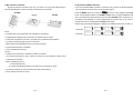
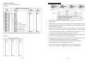
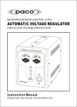
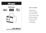
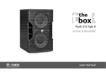
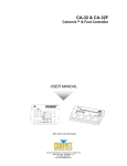
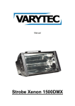
INDEX
1. General Instructions
2. Main Features
3. Lamp
4. How To Set The Unit
4.1 Control Panel
4.2 Main Function
5. How To Control The Unit
A. By master/slave preprogrammed function
B. By easy controller
C. By Colormix controller
D. By universal DMX controller
6. DMX Linking & Controls
7. Troubleshooting
8. Fixture Cleaning
User Guide
Professional Entertainment Technology
1A
1. General Instructions
2. Main Features
The following points are important for safety as well as for the smooth installation and
Voltage:AC 120V 60Hz or 230/240/250V 50/60 Hz
• Bulb:
performance of the unit.
J Type 230V 800W(Euro)
J Type 120V 500W(USA)
Unpack carefully and be sure that no damage has occurred during shipping.
• 3 dichroic mirrors red, blue, and green .
It is very important to ground the yellow/green conductor in order to meet regulations for
• With lamp saving switch-off function. When the unit receives stand by signal from a
safety.
easy controller or an universal DMX controller, it will switch off the lamp extending the
Do not connect the device to any dimmer pack or power pack.
lamp’s lifetime.
The electrical work that is necessary for installation must be done by qualified
Easy access for bulb change.
personnel .
Universal DMX addressing and control.
Be sure to locate the unit in a place with adequate ventilation at least 15 cm from the
The units can be linked together in a master/slave combination and run by built-in
walls and at least 100 cm from adjacent surfaces. Be sure that no ventilation slots are
programs.
blocked.
Compatible with easy controller or universal DMX controller.
Be careful that no liquids or other objects can enter the unit. If this ever happens,
DMX signal / sound activation LED indicators.
disconnect the main power immediately.
Fan cooled.
In the event of serious operating problems, turn off the unit immediately. Never try to
repair the unit yourself. Repairs carried out by non-qualified personnel can lead to
• Dimension : 285 x 295 x 460 mm
Weight : 8.8 kg
serious damage or malfunction. Please contact your dealer about authorized technical
assistance. Always use genuine spare parts.
3. Lamp
Occasional breaks are necessary to prevent breakdowns. This unit is not designed to
be used non-stop.
J Type 230V 800W(Euro)
Always remember to unplug the unit from the power mains before any service is done.
J Type 120V 500W(USA)
• Always switch off the mains supply and never handle the lamp or luminaire when
Please recycle the packaging.
it is hot.
• Do not touch the bulb with bare hands. If this does happen, clean the lamp with denatured
alcohol and wipe with a lint free cloth before installing.
• Change lamp:
Take off the dichroic glass as showing and change
the lamp. Re-screw the glass after changing the
G
lamp.
R
B
2A
3A
4. How To Set The Unit
4. 2 Main Function
To select any of the given functions, press the MENU button up to when the required one is
4.1 Control Panel
showing on the display. Select the function by ENTER button and the display will blink. Use
DOWN and UP button to change the mode. Once the required mode has been selected,
press the ENTER button to setup or it will automatically return to the main functions without
any change after idling 8 seconds. To go back to the functions without any change press the
DMX
MIC
MASTER
ONLY FOR REMOTE
CONTROL(CA-8)
MENU button. The main functions are showing below:
SLAVE
SOUND
DMX512 Address Setting
MENU
DOWN
UP
Setting 4 Channel
Setting 3 Channel
ENTER
DMX IN
DMX OUT
Blackout Mode " Yes Blackout "
Blackout Mode " No Blackout "
Dimmer Normal
Dimmer Inversion
MENU
Display
LED on
LED off
To show the various menus and the selected functions .
LED
Display Normal
Display Inversion
DMX
On
DMX input present
MASTER
On
Master Mode
Fixture Hours
SLAVE
On
Slave Mode
Reset
SOUND
Flashing
Sound activation
MENU
To select the programming functions
DOWN
To go backward in the selected functions
Press the MENU button up to when the
UP
To go forward in the selected functions
ENTER button and the display will blink. Use DOWN and UP button to change the DMX512
ENTER
To confirm the selected functions
address. Once the address has been selected, press the ENTER button to setup or
Button
DMX512 Address Setting
is showing on the display. Pressing
automatically return to the main functions without any change after 8 seconds. To go back to
the functions without any change press the MENU button again.
Remote controller input
By connect to the 1/4” microphone jack to control the unit for stand by, function and mode
Channel Mode
Microphone
To receive audio signal for sound activation .
Press the MENU button up to when the
is shown on the display. Pressing ENTER
DMX input/output
button and the display will blink. Use DOWN and UP button to select the
For DMX512 link, use 3-pin XLR plug cable to link the unit together.
Channel ) or
(4
(3 Channel) mode. Once the mode has been selected, press the
ENTER button to setup or automatically return to the main functions without any change
after 8 seconds. To go back to the functions without any change press the MENU button
again.
4A
5A
Fixture Hours
Blackout Mode
is showing on the display. Pressing
Press the MENU button up to when the
Press the MENU button up to when the
is blinking on the display. Pressing ENTER
ENTER button and the display will blink. Use DOWN and UP button to select the
button and the display will show the number of working hours of the unit. To go back to the
(yes blackout) or
(no blackout) mode. Once the mode has been selected, press
the ENTER button to setup or automatically return to the main functions without any change
functions press the MENU button again.
Reset
after 8 seconds. To go back to the functions without any change press the MENU button
again.
Press the MENU button up to when the
is blinking on the display. Pressing ENTER
button and the fixture will be reset. To go back to the functions press the MENU button
Dimmer Inversion
again.
is shown on the display. Pressing ENTER
Press the MENU button up to when the
button and the display will blink. Use DOWN and UP button to select the
or
(normal)
(dimmer inversion) mode. Once the mode has been selected, press the ENTER
5. How To Control The Unit
You can operate the unit in four ways:
button to setup or automatically return to the main functions without any change after 8
A. By master/slave preprogrammed function
seconds. To go back to the functions without any change press the MENU button again.
By linking the units in master/slave connection, the first unit will control the other units to
give an automatic, sound activated, synchronized light show. This function is good when you
Led Display
want an instant show. Its DMX input jack will have nothing plugged into it, and Its master
Press the MENU button up to when the
is showing on the display. Pressing ENTER
LED will be constantly on and sound LED will flash to the music. The other unit’s DMX
(Led on)
cables plugged into the DMX input jacks (daisy chain) and the slave led lights will constantly
button and the display will blink. Use DOWN and UP button to select the
or
(Led off) mode. Once the mode has been selected, press the ENTER button to
setup or automatically return to the main functions without any change after 8 seconds. To
go back to the functions without any change press the MENU button again.
on.
B. By easy controller(CA-8 & CA-8F)
The easy remote control is used only in master/slave mode. By connecting to the 1/4”
microphone jack of the first unit, you will find that the remote control on the first unit will
Display Inversion
control all the other units for Stand by, Function/Mode.
It is good for you to install the unit on the floor or under ceiling. Press the MENU button up to
when the
is blinking on the display. Use the ENTER button to change to the mode
(display inversion), It will automatically store after 8 seconds. Or press the ENTER
button again return to the mode
(display normal). To go back to the functions press
the MENU button again.
Display normal mode for the fixture putting on the floor.
Display inversion mode for the fixture fixing under ceiling.
6A
Stand By
Function
Blackout the unit
1.
Synchronous Strobe
2.
2-light Show Strobe
Full on/Color selection
(Hold on 3 seconds for full on)
Dimmer
Mode
Sound(LED Off)
Manual(LED On)
Latch(LED blinking)
7A
C. By Colormix controller
D. By universal DMX controller
By link the Colormix controler to the unit , you have to use 3 pin XLR cable and use 5
pin XLR cable between Colormix controller and Colormix foot controller.
If you use a universal DMX controller to control the units, you have to set DMX address from
1 to 512 channel so that the units can receive DMX signal.
Press the MENU button up to when the
is shown on the display. Pressing ENTER
button and the display will blink. Use DOWN and UP button to change the DMX512 address.
Once the address has been selected, press and keep ENTER button pressed up to when
the display stops blinking or storing automatically 8 seconds later. To go back to the
functions without any change press the MENU button again.
Please refer to the following diagram to address your DMX512 channel for the first 4 units.
4 Channels:
CA-32
• A professional, user friendly DMX 4ch.controller for colorimixing.
3 Channels:
• Equipped with 9 different hold-color buttons for instant access of colors.
• Comes with 32 spectrum mix colors, color fade, and 12 different chase patterns.
• Providing the richest changing colors for the show.
• Speed and dimmer adjustable for both color fade and chase.
• Sound activated function is available.
• Full on and Blackout functions .
CA-32F
• Colormix Foot controller is a extended controller of Colormix.
• To be liked with Colormix. Add a switch to change the control between Colormix and
Colormix Foot Controller.
• Mode i.) Blackout (LED on)
ii.) Hold Color(LED off)
iii.) Chase (LED blinking)-Stamp on the button over 2 seconds for chase
• Up and Down buttons:To select the hold colors and chase patterns.
• Full on: Stamp the button for full on.
8A
9A
• DMX512 Configuration
6. DMX Link & Controls
You can select 4 or 3 channels mode.
4 channels:
1. If you using a controller with 5 pins DMX output, you need to use a 5 to 3 pin
adapter-cable.
2. At last unit, the DMX cable has to be terminated with a terminator. Solder a 120 ohm
1/4W resistor between pin 2(DMX-) and pin 3(DMX+) into a 3-pin XLR-plug and plug it in
the DMX-output of the last unit.
3. Connect the unit together in a `daisy chain` by XLR plug from the output of the unit to the
input of the next unit. The cable can not branched or split to a `Y` cable. DMX512 is a
very high-speed signal. Inadequate or damaged cables, soldered joints or corroded
If you use CA-32 Colormix controller, the DMX value range of CH4 is from 100% to 0% .
connectors can easily distort the signal and shut down the system.
4. The DMX output and input connectors are pass-through to maintain the DMX circuit,
even when one of the units in the chain is power disconnected.
3 channels:
5. Each lighting unit needs to have an address set to receive the data sent by the controller.
The address number is between 0-511 (usually 0 & 1 are equal to 1).
6. The end of the DMX512 system should be terminated to reduce signal errors.
7. 3 pin XLR connectors are more popular than 5 pin XLR.
3 pin XLR: Pin 1: GND, Pin 2: Negative signal (-), Pin 3: Positive signal (+)
5 pin XLR: Pin 1: GND, Pin 2: Negative signal (-), Pin 3: Positive signal (+)
10 A
11 A
7.Troubleshooting
8. Fixture Cleaning
Following are a few common problems that you might encounter, and suggestions
as to how to solve them.
The cleaning of internal and external optical lenses and/or mirrors must be carried out
periodically to optimize light output. Cleaning frequency depends on the environment in
which the fixture operates: damp, smoky or particularly dirty surrounding can cause greater
accumulation of dirt on the unit’s optics.
A. No light
1. Check the power on LED and fuse
* Clean with soft cloth using normal glass cleaning products.
2. Check the lamp if it is ok? (The lamp may turn off, when the unit is in blackout mode).
* Always dry the parts carefully.
* Clean the external optics at least once every 20 days. Clean the internal optics at least
every 30/60 days.
B. Not responding to DMX
1. Check if the red LED is on, if not, check DMX connectors, cables and to see if they are
linked correctly.
2. If the red LED is on and no response to the control, check the dipswitch settings and
DMX polarity.
EC Declaration of Conformity
3. If you have intermittent DMX signal problems, check the pins on connectors or on PCB
of the unit or the previous one.
We declare that our products (lighting equipments) comply with the following
4. Try to use another DMX controller.
specification and bears CE mark in accordance with the provision of the
5. Check if the DMX cables run near or run alongside to high voltage cables that may
Electromagnetic Compatibility (EMC) Directive 89/336/EEC.
cause interference to DMX interface circuit.
EN55014-2: 1997 A1:2001, EN61000-4-2: 1995; EN61000-4-3:2002;
C. Some units don’t respond to the controller
EN61000-4-4: 1995; EN61000-4-5: 1995, EN61000-4-6:1996,
You may have a break in the DMX cabling. The unit receiving no DMX signal will begin
its own light show. Check the red LED for the response of the DMX signal.
EN61000-4-11: 1994.
&
Harmonized Standard
D. No response to the sound
1. Check the unit to make sure if it is not receiving DMX signal (red LED should be off).
EN60598-1: 2000+ALL:2000+A12:2002
2. Check the unit that is not set to auto chase mode.
Safety of household and similar electrical appliances
3. Check microphone to see if it is good by tapping the microphone.
Part 1 : General requirements
12 A
13 A
Technical Specifications
Power
Fuse
Lamps
Dimension
Weight
AC 120V 60Hz
AC 230/240/250V 50/60Hz
6X30mm Glass T15A
J Type 120V 500W
J Type 230V 800W
295mm x 285mm x 460mm
8.8 kg / 19.6 lbs
Innovation , Quality , Performance
14 A
15 A