1
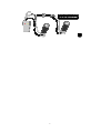
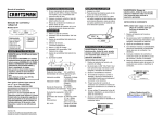
NET PROBE & TONER KIT
User’s Manual
TCT-680
WARNING – ELECTRIC SHOCK RISKS
*
*
*
*
Keep this unit away from water, moisture, and rain.
Contacting live circuits can cause serious injury.
Before using the test lead or accessory, check that it is clean and dry, and that the
insulation is in good condition.
Do not open the battery compartment when test leads are connected to a live
circuit, or when the unit is switched on.
Never connect this Toner or Net Probe to a live wire from a non-compatible telephone/
network system. Doing so may damage the tracer and/or the equipment.
* WARNING – LIVE CIRCUIT *
Acceptable voltage – The tester is designed to bear voltage conditions commonly found on
live telephone wires: it can safety be connected to wires carrying 48V DC or less, at less than
80 mA or 24 VAC.
Unacceptable voltage – Do not connect the tester to wires bearing over 48V DC or at 80
mA or 24VAC, or higher. Do not connect to live AC circuits. Doing so causes an extreme
shock hazard and damages the tester.
When connecting the tester to a previously untested circuit, the tester should always be in
OFF/VOLT mode (the middle switch on the top switched to the middle position).
The Net Toner & Probe Kit is a practical telecom and network installation, maintenance and
troubleshooting tool. The Net Toner has the unique feature of enhancing talk battery power
supply to allow communication over inactive pairs, using telephone test sets. It provides two
selectable tones which allow you to trace cable and locate faults for troubleshooting both
voice and data circuits.
It also tests cable continuity, tests Line 1, Line 2 polarity and can determine line polarity and
voltage in data and voice lines.
It features a tone signal, two alligator clips, a 4-conductor (RJ12) modular cable, an RJ45 jack
and an F- female optional coaxial connector for multiple connection options, which enable it
to test telecom, cat5 cabling coax cable, and bare wires.
The tone generated by the Net Toner can be easily traced by the Net Probe or any other
commercial probe. The Probe comes with adjustable volume control and signal LED for
enhanced accuracy. It also includes Ring / Tip polarity test indicators, an earphone jack for
noisy environments, modular jack and test pins for multiple connector options, low battery
indicator, easy tip replacement, and lanyards attachment point for hands-free operation.
When used in conjunction with the toner, the Net Probe allows you to trace and troubleshoot
Telecom/Datacom, security/alarm, CATV and audio cable systems.
This kit is a must-have tool for installation, service, and repair.
OPERATION:
A. SENDING/TRACING A TONE
1. Set the toggle switch on the Net Toner to〝TONE HI-LO〞position.
2. Plug the cable to be checked into the〝Tone/Cont〞jack of the tester or plug the
supplied alligators cable into the〝Tone/Cont〞jack.
3. Connect the tester to the cable to be traced using the RJ45 jack, the red alligator clip
on the RJ45-to-RJ11 patch cable, or the optional coaxial F connector. To
strengthen tone signal, you may connect the black alligator clip to a ground. (if
using the RJ45 jack to connect to the cable being traced, this will not be possible.)
4. Use the Net Probe to find the cable you have connected to. When the tip of the Net
Probe touches the right cable, the tone will be at its loudest and the〝signal〞LED
light will turn on. (You may turn the volume down as the tip gets nearer to the
1
right cable to help distinguish between the cables the Net Probe tip touches.)
5. Use the Tone button on the Net Toner to change the tone to 〝HI〞(down position) or
〝LO〞(up position.)
CAUTION: Do not connect to an active AC circuit exceeding 24V in this mode.
B. SUPPLY TALK BATTERY POWER:
The Net Toner has a feature which allows users to communicate using telephone test sets,
even when a circuit is dead.
1. Using the test leads, connect the Net Toner and a telephone test set to the inactive
circuit, in series, as illustrated.
2. Flip the toggle switch on the Net Toner to Cont/Talk position.
3. Set the TALK BATT button to〝Enhanced〞(down) position. This provides
additional battery power to enable voice communication over the inactive circuit.
4. You may now communicate using the telephone test sets.
C. TESTING CABLE CONTINUITY:
NOTE: Before testing for continuity, check line polarity to ensure that the line is
not powered.
1. Connect the red and back alligator test leads to the cable you want to test.
2. Flip the toggle switch on the Net Toner to CONT/TALK position.
3. The continuity LED indicator will light green. Bright green indicates a low resistance
path. Dim green indicates a high resistance path. Unlit indicates an open circuit.
Installed cables too long to test by alligator clips
1. Place a termination device on the far end of the cable, connecting the 2 pin that you
wish to test or simply connect the two wires manually.
2. Attach the alligator clips to the 2 pins that you wish to test.
3. Read results on the continuity LED. A lit LED indicates that the cable is continuous.
An unlit LED indicates that it has a break at some point.
D. COAX TESTING:
a. Test terminated coaxial cables.
Connect the red test lead to the connector housing and the black test lead to the center
pin, or to the ground.
b. Test un-terminated coaxial cables.
Connect the red test lead to the outer shield and the black test lead to the ground or to
the center conductor.
E. POLARITY TEST – IDENTIFYING TIP AND RING
1. Flip the toggle switch to the OFF/Polarity position.
2. Connect the red alligator test lead to the Ring (-) connection, and the black test lead
to the Tip (+) connection. Or connect a test cable with RJ12 or RJ45 plugs into the
RJ45 modular jack on the Net Toner.
3. To check Line 2 polarity, use the RJ45 jack or RJ11 modular plug connection.
Green indicates normal polarity
Red indicates reversed polarity
Flickering Red and Green indicates presence of AC power or a ringing line.
A dim LED indicates a busy or faulted line.
F. VERIFYING THE LINE:
1. In OFF/Polarity mode.
2. Connect the black lead to the Tip (+) connection, usually green or blue.
3. Connect the red lead to the Ring (-) connection, usually red or labeled R.
4. Or insert the 4-pin modular cable into the wall jack, or plug the line into RJ45 jack on
the Net Toner.
5. Dial the line to be verified. If the tester is connected to the correct line, the Line 1 LED
will flickering green and red.
6. Monitor the line and flip the toggle switch to continuity position. This will terminate
the call to confirm the identification.
When not in use, the Net Toner’s cables can be kept bundled and organized by using the
convenient Velcro cable strap attached to the cables near the Net Toner’s housing.
2
When battery power runs low, the low BATT light on the Net Toner will turn on. You
should change the battery immediately. Continuing to test with a low battery may produce
inaccurate results.
NET PROBE – TONE TRACING
1. Set the〝TEL/TRACE〞selector to〝TRACE〞↓position.
2. Push〝TRACE〞button and the probe end becomes active.
3. Hold〝TRACE〞button to trace a line or plug the tracer’s RJ45 jack into a wall outlet
using a jumper cable or connect the clip leads to test pins.
i. Tracing (for unknown cable path/termination) – Adjust gain (volume) control to
the desired level. Begin tracing from the tone generator. Slowly maneuver the tone
tracer away from the source. Take caution to avoid any high voltage sources.
Adjust the gain control whenever necessary to maintaining constant (or regain)
audio contact with the tone from the tone generator. Trace over the entire path of
the test cable or until the cable end is located.
ii.Locating (termination verification/general area of termination) – Adjust gain
(volume) control to the maximum level. Begin tracing in the general area of the
cable termination. Slowly maneuver the tone tracer in a zigzagging fashion
carefully and methodically over the entire area until the generated tone is found.
Take caution to avoid any high voltage sources. Adjust the gain control whenever
necessary to maintain constant (or regain) audio contact until the test cable is
located.
iii.Locating (conductor break/discontinuity) – Adjust gain (volume) control to the
medium – low level. Begin tracing the break starting from the tone generator.
Continue tracing along the path of the cable until the tone disappeared/diminished.
Adjust the gain control necessary to pinpoint/isolate the area of the break.
Tip: The tone is loudest when the tip of the tracer is near and parallel to the cable
carrying the tone signal.
Ear Jack:in noisy environments, 2.5mm headphones may be plugged into the jack
on the right side of the Net Probe, be sure to fully seat the plug into the jack.
Instruction – Line Testing
Use this function only on a compatible〝Analogue〞telecom and network system.
1. Set the〝TEL/TRACE〞selector from〝TRACE↓〞to〝TEL↑〞position.
2. Connect an RJ12 or RJ45 plug into the modular jack on the Tone Detective, Tone Tracer
or connect the tracer to a wall jack using a jumper cable or connect the clip leads to test
pins.
i. Identifying telephone line polarity and verifying telephone lines.
NORM. – The analogue telephone patch cable or the outlet is installed properly.
It indicates the telephone line carries proper voltage and correct
polarity.
REV. – The analogue telephone patch cable or the outlet is improperly wired.
It indicates the telephone line’s polarity is reversed.
If both NORM. and REV. LEDs are on at once, the voltage is AC, which is not
normal. Disconnect from the line and proceed with caution. One of the LEDs
being on solid indicates the presence of a DC voltage.
If both NORM. and REV. LEDs are flashing the line is ringing for phone number
verification.
If one or both NORM. and REV. LEDs are on, voltage is present on the center
pair of the RJ jack (4-5 on RJ45’s or 3-4 on RJ11’s. RJ12’s).
If no LEDs light, the cable is most likely not connected.
ii. Checking low voltage (less than 24 volts DC or AC only)
If the TEL is Green (NORM.) the black test lead is connected to a negative (-)
DC voltage.
If the TEL is Yellow (REV.) the black test lead is connected to positive (+) DC
voltage.
3
▲ Over current indicator (Net Probe I and II only)
The over current indicator lights when current on the line exceeds 90 (mA). Current
over 90 mA means that you may have connected to a digital line or an unusually
configured analog line. Note that if the line is digital, plugging an analog modem into it
will damage the modem. Disconnect the tester from the line within 10 seconds to avoid
causing damage to the tester.
▲ Testing Dial Tone (Net Probe II only)
1. Switch the〝LISTEN/TEL〞switch to〝LISTEN〞position.
2. Plug the phone line into tester’s RJ jack.
3. Push the〝LISTEN〞button to the down position, this takes the phone line off the
hook and plays sound on the phone line through the tester’s speaker.
4. Check for good dial tone.
☆ Testing phone line without RJ 11 plug
Connect phone line to the test pins on tester’s reverse side with alligator clip (not
included), then carry out test as described above.
NOTE: As soon as dial tone check is complete return the〝LISTEN/TEL〞switch to
〝TEL〞position, and push the〝LISTEN〞button to the up position to avoid
unnecessary drain on the Battery.
WARNING: If over current LED lights, the line being tested has more than 90 MA of current
and is probably a digital phone line, turn off the listen switch or unplug.
▲
Tip Replacement
1. To replace tracer tip, position probe to allow tracer tip pointing toward you,
2. Grasp tip with finger and turn gently COUNTER CLOCK – wise until tip separates
from probe body.
3. Replace old tip with a compatible new tip (included) and reverse step 1 and 2. DO
NOT OVER TIGHTEN or damage to tip may result.
▲ Battery low
1. Net Probe/Net Toner: The battery low indicator lights when the battery
(DC9V) need to be replaced.
2. Net Probe I and II: When the battery needs to be replaced, the LED indicators
will go dim and the speaker sound will weaken or fail.
Replace the battery.
▲
Battery Replacement
1. The Net Toner and Net-Probe require one standard / Alkaline 9 Volt battery for
operation.
2. Slide back the battery cover to replace new battery.
4
5
▲ SPECIFICATIONS
NET TONER
Toner
Hi alternating 500 – 781 HZ
Frequency:
Lo alternating 446 – 657 HZ
Talk battery: 9V into a 600 ohms circuit
Voltage protection: 50 VDC or 24 VAC
Battery: 9V DC, standard or alkaline
Size: 4.9〞x 2.7〞x 1.2〞(125 x 68 x 26mm)
Weight: 120g / 0.37lb / 60oz
NET PROBE
Gain: 30db
Tip resistance: 30 ohms (plastic tip)
Size: 8.1〞x 1.6〞x 1〞 (210 x 40 x 28mm)
Weight: 140g / 0.30lb / 5oz
Operating conditions: 0℃ to 40℃ / 32℉ to 104℉
CE Approved: The equipment was passed – EN 55022, class B for ITE and
EN 55024.
6