1
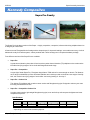
2010 Supra Assembly Instructions © Kennedy Composites 6/5/2010 Version 1.4 6/5/2010 Supra Assembly Instructions Kennedy Composites Supra Pro Family The Supra Pro is the latest version of the Supra - a highly competitive, composite, hollow-molded wing sailplane based on a design by Dr. Mark Drela. It features a new Fiberglass/Kevlar fuselage with a drooped nose for improved landings, a removable servo tray, a built-in ballast tube ready for a ballast system, carbon pushrods with Teflon housings and a complete hardware package. Four different versions of the Supra Pro are available: Supra Pro A great thermal duration plane that will out-launch any other thermal duration (TD) sailplane on the market at the incredible low flying weight of 62 oz. built with fiberglass skinned wings. Supra Pro - Competition A super-light, floater Supra Pro. Fiberglass wings feature T800 carbon for extra strength on launch. Tail features an 8% larger molded/built-up D-box horizontal stabilizer and a built-up rudder to minimize nose weight. Carefully built, this version has a flying weight of under 60oz. and a wing loading of ~8oz./sq. ft. Supra Pro - Carbon Lite The ultimate F3J sailplane with a carbon center section and fiberglass wing tips. Designed to take any two-man tow using monofilament tow line. Supra Pro - Competition Carbon Lite A carbon center section, light-weight fiberglass wing tips, boom and built-up tail compose the lightest and most competitive Supra Pro. Specifications: Wing Span Length Wing Area Flying Weight 134" 67" 1,052 sq. in. 58-65* oz. Wing Loading Controls Airfoil 8.2-8.9 oz./sq. ft. AFRE AG40/41/42/43 * depending on version and installed equipment Supra Family Assembly Instructions [1] Dfriant 6/5/2010 Supra Assembly Instructions Table of Contents Supra Introduction and Specifications 1 Table of Contents 2 Unpacking the Supra and Taking Inventory 3 Getting Started 5 Materials and Supplies you need to Assemble the Supra 6 Overview of the Supra Assembly Process 7 Quick Build Instruction Outline 8 Detailed Assembly Instructions 10 Fuselage Assembly 11 Rudder and Stabilizer Assembly 16 Wing Assembly 19 Installing the Battery, Receiver, and Optional electronics 21 Assembling the Supra for Flight 23 Balancing the Supra and Setting the Tow Hook Position 25 Flying Surface Deflection Control Throw Templates and Settings 26 Setting up Supra Control Throws by Vladimir Gavrilko 28 Supra Family Assembly Instructions [2] Dfriant 6/5/2010 Supra Assembly Instructions Unpacking the Supra and Taking Inventory Remove the Supra parts from their protective foam wrapping. Take inventory of the parts by comparing the parts with the diagrams below to ensure your kit is complete. If you find any discrepancy between the parts shown below and the contents of your kit contact Kennedy Composites to resolve any questions you have. Diagram showing the major components of a Supra kit: 1. Wing center section 2. Two Wing tips 3. Fuselage pod 4. Fuselage carbon boom with pushrods and stabilizer v-mount pre-installed 5. Stabilizer 6. Rudder 7. Bag of small parts 8. Bag with wing wiring harness 9. Not shown: Three sets of carbon Wing joiners NOTE: An optional competition landing skeg (not shown) is available for purchase separately from Kennedy Composites. A set of custom made ballast weight (not shown) is available for purchase separately from Kennedy Composites. 5 6 2 7 8 3 4 1 Supra Family Assembly Instructions [3] Dfriant 6/5/2010 Supra Assembly Instructions Diagram showing the contents of the small parts bag (part 7, page 3): 1. Forward Wing mounting screw (one spare). 2. Rear Wing mounting screw (one spare). 3. Allen wrench for Wing screws. 4. Wing top hatch covers for flap and aileron Wing pushrod clevis and horns. 5. Rudder horn. 6. Flap pushrods. 7. Aileron pushrods. 8. Aileron and flap horns. 9. Clevis for ailerons and flaps. 10. Clevis for rudder and elevator pushrods. 11. Tips to secure rudder and elevator pushrods to clevis. 12. Screw to secure Stabilizer to v-mount (spare). 13. Screw to secure ballast in place in ballast tube (ballast weight is a separate product not included in the kit). 14. Rudder and Stabilizer servo tray and servo tray rails (3 pieces). 15. Servo tray screws to secure servo tray to the servo rails. 16. Flap and aileron servo hatch covers. 16 Supra Family Assembly Instructions [4] Dfriant 6/5/2010 Supra Assembly Instructions Getting Started 1. Review the complete assembly manual to become familiar with the instructions. 2. Get the materials and supplies you will need to assemble the Supra (page 6). 3. Acquire the radio system you will use for the Supra. Recommended radio system, at a minimum, must support the following functions: o Rudder o Elevator o 2-Ailerons o 2-Flaps Recommended radio system at a minimum should provide the following mixing functions: o Aileron differential o Flap/elevator mixing o Aileron/rudder mixing o Dual rates o Exponential servo travel Nice to have: o Launch mode o Speed mode o Cruise mode o Thermal mode o Landing mode Kennedy Composites recommends the following minimum torque specification for the servos installed in the Supra. Servos Minimum Torque Rudder servo 40 oz/in Elevator servo 40 oz/in Ailerons servos 40 oz/in Flaps servos 60 oz/in 4. Read the ‘Overview of the Assembly Process’ (page 7) 5. Begin assembling the Supra. Quick Build Outline begins on page 8. Detailed Build Instructions begin on page 10. Supra Family Assembly Instructions [5] Dfriant 6/5/2010 Supra Assembly Instructions Materials and Supplies Needed to Assemble the Supra The following lists the minimum materials and supplied needed to assemble a Supra. These items are not included in the kit. Adhesives: 24 hour laminating epoxy 15 min epoxy Medium thick CA glue Blue Locktite (to tighten pushrods and clevis to reduce slop in the linkages) Role of fiber reinforced strapping tape (for securing the Wing tips onto the Wing center section) Tools and Materials: Epoxy thickening agent Flux brushes, or equivalent, for applying epoxy Paper towels Small Phillips blade screwdriver Small straight blade screwdriver Pliers Small mixing cups Mixing sticks (popsicle sticks) Dremel tool with cutting wheel Exacto style razor knife and extra blades Masking tape Measuring calipers, or ruler, or tape measure Electronic servo centering and test device (highly recommended, not required) Model balancing stand for setting the center of gravity (CG). Set of templates for setting the deflection angles for the flaps and ailerons Padding for protecting battery and receiver Supra Family Assembly Instructions [6] Dfriant 6/5/2010 Supra Assembly Instructions Overview of the Assembly Process The assembly process is organized into 7 main stages. 1. Fuselage 2. Rudder and Stabilizer 3. Wing 4. Receiver and Battery Installation 5. Assembling the Supra for Flight 6. Balancing and Setting the Center-of-Gravity (CG) 7. Flying-Surface Templates and Deflection Settings Note that programming your specific transmitter is not included in this manual Please refer to your transmitter user manual for specific programming instructions Total assembly time can range between 5 and 10 hours of actual hands on time depending on experience. Due to the use of 24-hour laminating epoxy for a few assembly steps, the Supra cannot be built in one day. For the steps that use the laminating epoxy it will need to cure overnight before continuing. There are 2 steps that require the use of laminating epoxy: Cementing the carbon fuselage boom to the fuselage pod, and, Cementing the servo tray inside the fuselage If you were to perform these two steps first you could then build the Supra in one day, if required. Building the Supra in one day is not recommended. The assembly and construction instructions described in this manual are based on “best practices” techniques and procedures. The instructions can be augmented by your own experience, technique, and skill set. For many builders the instructions are simply a guide to ensure you perform each step and you do not build yourself into a corner. Due to the different skill levels of people building a Supra the instructions are organized and presented in two formats. Instruction format 1 is a quick build format which consists of an outline of the assembly process with page references to the detailed instructions if needed, and, Instruction format 2 is a detailed step-by-step format with comprehensive instructions illustrated with photographs. Whether you use the quick build instructions or the detailed instructions the Supra is assembled in the same order with both sets of instructions. Supra Family Assembly Instructions [7] Dfriant 6/5/2010 Supra Quick Build Assembly Instructions Quick Build Instruction Outline The quick build outline is intended to be used as a guide for experienced builders. It will ensure the Supra is assembled in the correct order and also ensure that no step is overlooked. Page references are provided for each step in the 7 main stages to point the builder to the page in the manual where the corresponding detailed instructions are located. 1. FUSELAGE ASSEMBLY Step 1: Epoxy the carbon boom (part 4, page 3) onto the fuselage (part 3, page 3) Use the recommended procedure to ensure the boom is aligned straight and true to the fuselage Use 24-hour laminating epoxy for the most secure bond between the boom and fuselage Step 2: Epoxy the 3-piece servo tray (part 14, page 4) inside the fuselage P. 15 NOTE: Do not install the rudder and stabilizer pushrods to the servos yet Step 4: Install a receiver on/off switch in the servo tray if desired P. 13 Use 24-hour laminating epoxy for the most secure bond between the tray and fuselage Step 3: Install the rudder and stabilizer servo into the servo tray P. 11 P. 15 Some people choose not to use a conventional on/off switch to save weight Step 5: Install the wing wiring harness (part 8, page 4) inside the fuselage P. 15 Step 6: OPTIONAL: Install the landing skeg mounting bracket inside the fuselage P. 16 The optional landing skeg is purchased separately from Kennedy Composites 2. RUDDER and STABILIZER INSTALLATION Step 1: Install the Stabilizer Pushrod onto the Stabilizer V-mount In order to fit the pushrod clevis into the hole in the Stabilizer rocker arm, carefully twist a 1/16" drill bit through the hole in the bottom of the v-mount with your fingers Step 2: Install the Rudder Pushrod Horn (part 5, page 4) onto the Rudder (part 6, page 3) P. 17 Remove the carbon pin that spans across the inside end of the carbon boom and slide the Rudder onto the end of the boom. Press the carbon pin through the Rudder and boom Step 4: Install the Stabilizer (part 5, page 3) onto the V-mount with Stabilizer Screw (part 12, page 4) P. 19 Cut the Teflon tubing that surrounds the Stabilizer pushrod to length. Cut the Stabilizer pushrod to length. CA the pushrod tip onto the end of the pushrod and crimp in place with pliers. Screw the Stabilizer clevis onto the pushrod tip. Install the clevis onto the servo Step 6: Install the Rudder Pushrod (requires parts 10 & 11, page 4) onto the Rudder Servo P. 18 Place the Stabilizer onto the v-mount and secure it in place with the Stabilizer screw Step 5: Install the Stabilizer pushrod (requires parts 10 & 11, page 4) onto the Stabilizer Servo P. 17 Attach the Rudder horn onto the base of the Rudder using medium thick CA glue Step 3: Install the Rudder onto the Carbon Boom P. 16 P. 19 Cut the teflon tubing that surrounds the Rudder pushrod to length. Cut the Rudder pushrod to length. CA the pushrod tip onto the end of the pushrod and crimp in place with pliers. Screw the Rudder clevis onto the pushrod tip. Install the clevis onto the servo Supra Family Assembly Instructions [8] Dfriant 6/5/2010 Supra Quick Build Assembly Instructions 3. WING ASSEMBLY Step 1: Install the Flap servos, pushrods (parts 6 & 9, page 4) , and control horns (part 8, page 4) in the center section of the Wing (part 1, page 3) Install servos, control horns, and pushrods as desired Step 2: Install the Aileron servos, pushrods (parts 7 & 9, page 4), and control horns (part 8, page 4) in the tip sections of the Wing P. 20 Install servos, control horns, and pushrods as desired Step 3: Install the Flap and Aileron pushrod and servo covers (parts 4 & 16, page 4) P. 20 P. 21 The Flap and Aileron pushrod and servo covers are best installed at the end of the Supra assembly once the Flap and Aileron pushrods have had all final adjustments made in order to keep from needing to remove and reinstall them during the adjustment period 4. INSTALL the BATTERY, RECEIVER, and OPTIONAL ELECTRONICS Step 1: Install the battery (not included in kit) P. 21 Battery is installed most forward in the fuselage Step 2: Install the receiver (not included in kit) Receiver is installed behind the battery and in front of the servo tray P. 22 Step 3: Install optional electronics (not included in kit) P. 22 Options include voltmeters, GPS systems, and other electronics 5. ASSEMBLING the SUPRA for FLIGHT Step 1: Install the Rudder (May be necessary if you built the Supra with the removable rudder) P. 23 Step 2: Install the Stabilizer onto the V-mount P. 23 Step 3: Install the Wing center section onto the Fuselage P. 23 Step 4: Install the Wing tips onto the Wing Center Section P. 23 Step 5: Tape the Wing tips to the Wing Center Section P. 23 6. BALANCING the SUPRA and SETTING the TOW HOOK POSITION Step 1: Initial balance point for the Supra P. 25 Recommended balance point for the CG is 4 inches behind the leading edge of the wing at the root Step 2: Set the initial tow hook location P. 25 Position the tow hook in front of the CG as desired 7. FLYING SURFACE CONTROL THROW TEMPLATES and SETTINGS Set the flap and aileron deflections with deflection templates P. 26 Use the included drawings to make flap and aileron deflection templates P. 28 Setting up Supra Control Throws by Vladimir Gavrilko Supra Family Assembly Instructions [9] Dfriant 6/5/2010 Supra Detailed Assembly Instructions DETAILED ASSEMBLY INSTRUCTIONS Specifications Wingspan: 3400mm (133.85") Length: 1700mm (67") Weight ( without ballast ) Supra Competition Glass: 1600g (56.4 oz) Supra Competition Carbon/Glass: 1700g (60 oz) Wing area: 69.34 sq dm(1052 sq in) Wing airfoil: AG40/AG41/AG42/AG43 Stabilizer area: 6.2 sq dm (96.1 sq in) Stabilizer airfoil: HT14/HT15 Rudder area: 4.9 sq dm (76 sq in) Rudder airfoil: HT13/HT12 Controls: Elevator, Rudder, Ailerons, Flaps Supra Family Assembly Instructions [10] Dfriant 6/5/2010 Supra Detailed Assembly Instructions FUSELAGE ASSEMBLY The Fuselage assembly consists of 6 steps detailed below. Step 1: Epoxy the Carbon Boom onto the Fuselage Tools, Materials, and Parts required for this step: Laminating epoxy and thickening agent Small brush to apply epoxy (Recommend inexpensive flux brush) 12 feet of string (Used to ensure boom and fuselage are aligned straight and true to each other) Masking tape (Used to mask off the ends of the boom and the fuselage to protect from excess epoxy) Carbon boom with pre-installed pushrods (part 4, page 3) Fuselage (part 3, page 3) Assembly procedure: 1. Mask off the end of the fuselage and the end of the carbon boom where they will be joined together on the outside of the parts as shown in figure 1. The masking will protect the two parts from getting epoxy on the outside surface. Mask to edge Mask to edge Figure 1: Ends of Fuselage and Boom masked off 2. Prepare a mixture of thickened epoxy. Mix ½ oz of 2-part laminating epoxy with thickening agent until the mixture is the consistency of whipped cream. 3. Brush thickened epoxy on the end of the fuselage and inside the end of the boom where the two parts will mate together as shown in figure 2. Apply epoxy for first 2 inches inside the end of the boom Apply epoxy around the fuselage in this area that will fit inside the boom Ballast tube Figure 2: Identifies where to apply thickened epoxy Supra Family Assembly Instructions [11] Dfriant 6/5/2010 Supra Detailed Assembly Instructions 4. Insert the end of the fuselage into the end of the boom and wipe off any excess epoxy that may ooze out between the fuselage and boom. IMPORTANT: The pushrods are first inserted through the hole beside the ballast tube on the right side of the end of the fuselage as the boom and fuselage are mated together. See figures 3 & 4 for illustration. Fuselage and boom mated together with no gap between them Ballast tube Insert pushrods through hole next to ballast tube Masking tape protecting fuselage and boom Figure 3: Pushrod placement in Fuselage Figure 4: Fuselage and Boom fit together 5. Lay the fuselage and boom upside down on the workbench with the wing mount platform resting flat on the workbench and the stabilizer v-mount platform resting flat on the workbench. Laying both parts upside down on the workbench aligns the Wing and Stabilizer parallel to each other. Tape the Wing platform to the workbench, press the boom tight to the fuselage, and then tape the Stabilizer v-mount to the workbench. Figure 5: Shows fuselage and boom epoxied together, and secured to the table 6. Align the boom straight with the fuselage using the string method. Cut a piece of string the length of the fuselage and boom put together. Tape the string to the rear-end of the boom and pull it straight to the front of the fuselage. The string should lie directly down the centerline of the fuselage and boom when looking down on the fuselage and boom. Adjust the boom side to side as required to ensure perfect alignment between the fuselage and boom as shown in figure 6. Supra Family Assembly Instructions [12] Dfriant 6/5/2010 Supra Detailed Assembly Instructions String on center String off center Figure 6: Shows misalignment on the left and alignment on the right Repeat this procedure along the side of the boom and fuselage to ensure the boom and fuselage are aligned straight in the vertical direction as shown in figure 7. Support the boom where necessary to maintain alignment while the epoxy hardens. String off center String on center Figure 7: Shows misalignment on the left and alignment on the right 7. Allow the epoxy to harden overnight. Step 2: Epoxy the 3-piece Servo Tray inside the Fuselage Tools, Materials, and Parts required for this step: Laminating epoxy and thickening agent Small brush to apply epoxy (Recommend inexpensive flux brush) Pencil or thin felt pen (For marking the location of the servo tray inside the fuselage) 3-piece servo tray (part 14, page 4) 4 servo tray screws (part 15, page 4) Determine where the servo tray will be installed in the fuselage: Awareness of where the optional landing skeg, battery, and receiver will be installed is necessary to position the servo mounting tray. The exact location of where the tray is installed inside the fuselage is a personal preference. You can either install the tray leaving room for the receiver to be installed in front of the tray, or you can install the tray more forward and install the receiver behind the tray. Supra Family Assembly Instructions [13] Dfriant 6/5/2010 Supra Detailed Assembly Instructions Either way we recommend you test fit your battery, receiver, and servo tray into place to determine the exact position where the tray will be installed. Note that the tray is to be positioned with the on/off switch cutout located towards the back of the fuselage as shown in figure 8. Assembly and Installation procedure: 1. The servo and switch tray is composed of 3 parts, 2 side rails and the tray itself. Press the servo tray into its rails and screw the 4 screws in place to secure the tray in place as shown in figure 8. This will allow the tray to be cemented into place in the fuselage as one unit. Rail Assembled tray Servo tray Rail On/off switch Screws (4 places) Figure 8: Shows servo tray assembly 2. Test fit the servo tray with the mounting rails in its location inside the fuselage as shown in figure 9. Masking tape used to position tray Figure 9: Shows tray in place in the fuselage 3. When you have determined the location for the servo tray, lightly sand the inside of the fuselage where the servo tray will be cemented to the fuselage and wipe clean with alcohol to clean any oils and dust. Place the servo tray inside the fuselage and ensure the tray is level. Using a pencil or fine felt tip pen trace the location of the tray on the side of the fuselage. Remove the tray and prepare to epoxy it permanently in place. 4. Prepare a mixture of thickened laminating epoxy. Mix ½ oz of 2-part laminating epoxy with thickening agent until the mixture is the consistency of whipped cream and can stand up on its own. 5. Epoxy the servo tray permanently into place. Apply a coat of the thickened epoxy to the inside of the fuselage along the entire location where the tray will be installed. Apply a coat of the thickened epoxy along the sides of the servo tray rails where the rails will contact the inside of the fuselage. Ensure that the correct side of the tray is facing up in the fuselage and then carefully place the tray inside the fuselage and align the top of the tray with the lines that were drawn on the side of the fuselage. Supra Family Assembly Instructions [14] Dfriant 6/5/2010 Supra Detailed Assembly Instructions Wipe any excess epoxy off of any area that is not desired. Ensure the tray is level and then walk away from the project for 12 hours or until the epoxy has sufficiently hardened. Step 3: Install the Rudder and Stabilizer Servos in the Servo Tray (parts not included in kit). 1. The Rudder servo is installed in the forward servo location in the tray and the Stabilizer servo is installed in the rear servo location in the tray as shown in figure 10. 2. DO NOT install the Rudder and Stabilizer pushrods onto the servos at this time. The pushrods will be installed onto the servos after the pushrods are installed onto the Stabilizer v-mount and onto the Rudder horn. Step 4: Install the On/Off Switch in the Servo Tray (part not included in kit) 1. Fit the on/off switch in the servo tray, if desired. Step 5: Install the Wing Wiring Harness in the Fuselage Parts required for this step: Wing wiring harness (part 8, page 3) Assembly and Installation procedure: 1. The wiring harness provides the electronic interface between the receiver and the Flap and Aileron servos installed in the Wing. Install the wiring harness as described below. Place the servo ends of the wiring harness through the opening in the top of the fuselage where the Wing is installed. Hold the Fuselage vertical and feed the wires down through the opening in the Fuselage wing mount platform under the servo tray, and into the front of the fuselage as shown in figure 10. Wing wire harness Rudder servo Wing wire harness Stabilizer servo Figure 10: Servos and Wing wire harness installed Step 6: OPTIONAL: Install the Landing Skeg (Landing Skeg is purchased separately) 1. If you have purchased the optional Landing Skeg you can install it now. 2. The Landing Skeg installation instructions are provided in a separate document. The document can be downloaded from the Kennedy Composites website. 3. Read and follow the Landing Skeg Installation instructions. 4. When installed correctly the Landing Skeg will look like figure 11. Supra Family Assembly Instructions [15] Dfriant 6/5/2010 Supra Detailed Assembly Instructions Figure 11: Shows Landing Skeg Installed RUDDER and STABILIZER INSTALLATION The Rudder and Stabilizer assembly consists of 7 steps detailed below. Step 1: Install the Stabilizer Pushrod onto the Stabilizer V-mount Tools required for this step: Small straight blade screwdriver (spread the clevis apart) 1/16” drill bit (enlarge the v-mount clevis hole, if required) Installation procedure: 1. Using a small straight blade screwdriver spread the Stabilizer clevis apart and place the clevis pin into the hole in the v-mount. If the hole in the v-mount is too small to allow the clevis pin to fit, twist a 1/16” drill bit through the hole to enlarge the hole. Use your fingers to twist the drill bit through the hole. See figure 12 for a properly installed pushrod on the v-mount. Figure 12: Stabilizer pushrod clevis installed on v-mount Step 2: Install the Rudder Pushrod Horn onto the Rudder Tools, Materials, and Parts required for this step: Rudder horn (part 5, page 4) Rudder (part 6, page 3) Medium CA glue Small straight blade screwdriver (spread the clevis apart) Supra Family Assembly Instructions [16] Dfriant 6/5/2010 Supra Detailed Assembly Instructions Installation procedure: 1. Attach the Rudder horn onto the base of the Rudder using medium thick CA glue as shown in figure 13. Horn fits around piece of carbon at base of Rudder Figure 13: CA the Rudder horn in place on the base of the Rudder Step 3: Install the Rudder onto the Carbon Boom Tools, Materials, and Parts required for this step: Rudder (part 6, page 3) Small straight blade screwdriver (spread the clevis apart) Medium CA glue Installation procedure: 1. Press the fixing pin out of the Boom. The fixing pin is located inside the back of the Carbon Boom. 2. Slide the Rudder onto the Carbon Boom and align the hole in the Rudder mount with the fixing pin hole in the Carbon Boom as shown in figure 14. RUDDER Figure 14: Shows the Rudder fixing pin location 3. Press the fixing pin back into the hole through the Rudder mount and the Carbon Boom. 4. A drop of medium thick CA glue can be placed on both ends of the fixing pin inside the boom to secure the pin from vibrating loose. 5. If you want to be able to remove the Rudder you can place a piece of tape over both ends of the fixing pin on the outside of the Rudder mount instead of CA glue. Remove the Rudder from the boom by removing the tape and the pin and pulling the Rudder off the boom. 6. Using a small straight blade screwdriver open the clevis and fit the clevis pin onto the Rudder horn. If the diameter if the hole in the Rudder horn is too small for the pin to fit through use a 1/16” drill bit to enlarge the hole by twisting the drill bit through the hole with your fingers. 7. When properly installed the Rudder should look like figure 15. Supra Family Assembly Instructions [17] Dfriant 6/5/2010 Supra Detailed Assembly Instructions Figure 15: Shows the Rudder and Rudder pushrod installed Step 4: Install the Stabilizer onto the V-mount Tools and Parts required for this step: Stabilizer (part 5, page 3) Stabilizer mounting screw (part 12, page 4) Small straight blade screwdriver Installation procedure: 1. Place the Stabilizer onto the Stabilizer v-mount. 2. Secure the Stabilizer onto the v-mount with the Stabilizer screw. 3. When the Stabilizer is installed properly it will look like figure 16. Figure 16: Shows the Stabilizer and Stabilizer pushrod installed Step 5: Install the Stabilizer Pushrod onto the Stabilizer Servo Tools, Materials, and Parts required for this step: Pushrod tips (part 11, page 4) Pushrod clevis (part 10, page 4) 1/16” dia. drill bit (enlarge the servo horn holes if required) Small straight blade screwdriver (spread the clevis apart) Pliers (to crimp pushrod tips onto pushrod) Supra Family Assembly Instructions [18] Dfriant 6/5/2010 Medium CA glue Supra Detailed Assembly Instructions Installation procedure: 1. Center the servo and set the servo horn at neutral position as shown in figure 17. 2. Screw the Rudder clevis onto the pushrod tip. 3. Install the clevis onto the servo. 4. Cut the pushrod Teflon tubing to length ½” behind pushrod tip when servo horn is at neutral position. 5. Cut the Rudder pushrod to length with a Dremel cutting wheel. Pushrod fits into the end of the pushrod tip. 6. CA the pushrod tip onto the end of the pushrod and crimp in place with pliers. 7. When the pushrod is properly installed the servo will look like figure 17. Pushrod tip Servo horn @ neutral position Rudder Servo ½” Teflon tube Stabilizer Servo Figure 17: Shows the Rudder and Stabilizer pushrods installed Step 6: Install the Rudder Pushrod onto the Rudder Servo Tools, Materials, and Parts required for this step: Same tools, materials, and parts as step 5 above Installation procedure: 1. Center the servo and set the servo horn at neutral position as shown in figure 17. 2. Screw the Rudder clevis onto the pushrod tip. 3. Install the clevis onto the servo. 4. Cut the pushrod Teflon tubing to length ½” behind pushrod tip when servo horn is at neutral position. 5. Cut the Rudder pushrod to length with a Dremel cutting wheel. Pushrod fits into the end of the pushrod tip. 6. CA the pushrod tip onto the end of the pushrod and crimp in place with pliers. 7. When the pushrod is properly installed the servo will look like figure 17. WING ASSEMBLY The Wing assembly consists of 3 steps detailed below. Step 1: Install the Flap Servos, Pushrods and Control Horns in the Center Section of the Wing Materials, and Parts required for this step: Wing (part 1, page 3) Supra Family Assembly Instructions [19] Dfriant 6/5/2010 Flap servos (not included in kit) Supra Detailed Assembly Instructions Flap servo frames if desired (not included in kit) Flap Pushrods (part 6, page 4) Flap clevis (part 8, page 4) Flap control horns (part 9, page 4) Flap servo covers (part 16, page 4) Blue Locktite (for tightening the flap pushrods in their clevis to reduce slop) Installation procedure: 1. Screw the control horns in place in the flaps on the top of the wing. See figure 18. 2. Install the flap servos in the servo bays on the bottom of the wing with 15-minute 2-part epoxy. See figure 18. 3. Install the flap pushrods from the servo horn through the Wing and onto the flap horn. Not shown for clarity. 4. Adjust the depth of the flap horns and the length of the flap pushrods in order to achieve unrestricted movement between the pushrods and the flaps to ensure the pushrods do not contact the Wing at any point throughout the servo travel. 5. When you are satisfied with the pushrod installation apply Locktite to the threads on the clevis and pushrods to tighten any movement in the pushrod installation. Masking tape protecting Wing section Control Horn installed on top of flaps and ailerons Masking tape holding servo in place while epoxy hardens Servo installed Figure 18: Shows a control horn installed, shows a servo being installed, and a servo installation completed (Pushrod not shown for clarity) Step 2: Install the Aileron Servos, Pushrods and Control Horns in the Tip Sections of the Wing Materials, and Parts required for this step: Wing (part 1, page 3) Aileron servos (not included in kit) Aileron servo frames if desired (not included in kit) Aileron Pushrods (part 6, page 4) Aileron clevis (part 8, page 4) Aileron control horns (part 9, page 4) Aileron servo covers (part 16, page 4) Blue Locktite (for tightening the Aileron pushrods in their clevis to reduce slop) Installation procedure: Supra Family Assembly Instructions [20] Dfriant 6/5/2010 Supra Detailed Assembly Instructions 1. Screw the control horns in place in the ailerons on the top of the wing. See figure 18. 2. Install the aileron servos in the servo bays on the bottom of the wing with 15-minute 2-part epoxy. See figure 18. 3. Install the aileron pushrods from the servo horn through the Wing and onto the aileron horn. 4. Adjust the depth of the aileron horns and the length of the aileron pushrods in order to achieve unrestricted movement between the pushrods and the ailerons to ensure the pushrods do not contact the Wing at any point throughout the servo travel. 5. When you are satisfied with the pushrod installation apply Locktite to the threads on the clevis and pushrods to tighten any movement in the pushrod installation. Step 3: Install the Flap and Aileron Pushrod Covers and Servo Covers Materials, and Parts required for this step: Wing (part 1, page 3) Wing tips (part 2, page 3) Aileron and flap servo covers (part 16, page 4 Aileron and flap pushrod covers (part 4, page 4) Medium CA glue or double-faced tape, as desired Installation procedure: 1. The Flap and Aileron pushrod and servo covers are best installed at the end of the Supra assembly once the Flap and Aileron pushrods have had all final adjustments made in order to keep from needing to remove and reinstall them during the adjustment period. 2. Trim the covers to fit the opening defined in the surface of the Wing and install them in place with CA glue or tape. INSTALL the BATTERY, RECEIVER, and OPTIONAL ELECTRONICS The battery, receiver, and electronics installation consists of 3 steps detailed below. Step 1: Install the Battery Materials and Parts required for this step: Battery (not included in kit) Foam padding for the battery (not included in the kit) Installation procedure: 1. The battery is installed in the most forward location in the fuselage. See figure 19 below which shows the battery and receiver installation. 2. Wrap the battery in protective padding before installing it in place in the fuselage Supra Family Assembly Instructions [21] Dfriant 6/5/2010 Supra Detailed Assembly Instructions Ballast Tube Battery Balance weight if required Receiver Rudder & Stabilizer Servos Optional Electronics Figure 19: Shows the battery, receiver, and servo location Step 2: Install the Receiver Materials and Parts required for this step: Receiver (not included in kit) Foam padding for the receiver (not included in the kit) Installation procedure: 1. The receiver is installed behind the battery and in front of the servos as shown in figure 19 above. 2. Wrap the receiver in protective padding before installing it in the fuselage. Step 3: Install Optional Electronics Parts required for this step: Optional electronics (not included in kit) o Voltmeter o GPS o Video Camera Installation procedure: 1. Optional electronics that enhance your flying experience can include devices such as on-board voltmeters, GPS systems, and video cameras, to name a few. 2. Follow the manufacturer’s recommended installation instructions for any device you choose to install. 3. Pay attention to how optional devices may affect the center-of-gravity. Supra Family Assembly Instructions [22] Dfriant 6/5/2010 Supra Detailed Assembly Instructions ASSEMBLING the SUPRA for FLIGHT The Supra assembly procedure consists of 5 steps outlined below. Assembly Procedure: Step 1: Install the Rudder (This step may be necessary if you built the Supra with the removable Rudder) 1. Slide the Rudder onto the carbon boom until the holes in the Rudder mount line up with the holes in the carbon boom as shown in figure 20. 2. Press the fixing pin in place through the Rudder mount and the carbon boom as shown in figure 20. 3. Place a piece of fiber reinforced strapping tape over the fixing pin, or CA in place. 4. Install the Rudder pushrod clevis onto the Rudder horn as shown in figure 20. Step 2: Install the Stabilizer onto the V-mount 1. Place the Stabilizer onto the v-mount platform. 2. Screw the Stabilizer onto the v-mount with the Stabilizer screw as shown in figure 21. Step 3: Install the Wing Center Section onto the Fuselage 1. Hold the middle Wing center section near the Wing mount platform and connect the wire harness protruding from the fuselage Wing mount platform to the Wing as shown in figure 22. 2. Place the Wing center section onto the Wing mount platform and line up the two bolt holes in the Wing with the 2 bolt holes in the Wing platform as shown in figure 23. 3. Screw the two Wing mounting bolts into place through the Wing and into the Wing mount platform and tighten with the included Allen wrench as shown in figure 23 (the longer bolt installs in the hole towards the leading edge of the Wing, the shorter bolt installs in the hole towards the trailing edge of the Wing). Step 4: Install the Wing tips onto the Wing Center Section 1. Place the right and left Wing tips next to right and left ends of the Wing center section as shown in figure 24. 2. Press the carbon Wing joiner into the Wing tip as shown in figure 24. 3. Connect the Wing tip servo wire to the wire harness in the end of the Wing center section as shown in figure 24. 4. Press the carbon joiner and Wing tip into the joiner tube in the Wing center section as shown in figure 25. 5. Repeat this process to install the second Wing tip Step 5: Tape the Wing tips to the Wing Center Section 1. Wrap a piece of fiber reinforced strapping tape around the connection between the Wing tips and the Wing center section as shown in figure 26. 2. Place a 3” strip of fiber reinforced strapping tape between the Wing tip and the Wing center section at the trailing edge of the wing, in front of the flap and ailerons as shown in figure 26. NOTE: The tape ensures the Wing tips do not spread apart from the Wing center section upon landing. Supra Family Assembly Instructions [23] Dfriant 6/5/2010 Supra Detailed Assembly Instructions Place tape over fixing pin Rudder mounts fit around carbon boom Pushrod clevis installed on Rudder horn Figure 20: Install the Rudder onto the carbon boom and install the pushrod clevis onto the Rudder horn Figure 21: Install the Stabilizer onto the v-mount Figure 22: Connect the Wing wire harness Figure 23: Attach the Wing to the Fuselage with 2 bolts Figure 24: Install the Wing tip onto the center section Figure 25: Wing tip installed on Wing center section Figure 26: Wing tip taped to Wing center section Supra Family Assembly Instructions [24] Dfriant 6/5/2010 Supra Detailed Assembly Instructions BALANCING the SUPRA and SETTING the TOW HOOK POSITION Balancing the Supra and Setting the Tow Hook position consists of 2 steps detailed below. Step 1: Balancing the Supra Materials and Tools required for this step: Ballast weight (not included in kit) (ex: lead shot embedded in modeling clay) CG balancing tool Installation procedure: 1. The initial balance point for the Center-of-Gravity is located 4 inches behind the leading edge of the Wing at the root. 2. Assemble the Supra and set the plane on the balancing tool at the desired balance point. If necessary add weight to the very front of the fuselage until the desired balance point is achieved. 3. Adjust the balance point to your personal preference after a few test flights. Step 2: Setting the Tow Hook Position Tools required for this step: Phillips head screwdriver Adjustment procedure: 1. Set the initial tow hook position ¼” in front of the Center-of-Gravity. 2. Loosen the tow hook adjustment screw and move the tow hook into the desired position. See figure 20. 3. Adjust the tow hook position to your personal preference after a few test flights if necessary. Tow hook Tow hook adjustment screw Figure 20: Tow hook and tow hook adjustment screw Supra Family Assembly Instructions [25] Dfriant 6/5/2010 Supra Detailed Assembly Instructions FLYING SURFACE CONTROL THROW TEMPLATES and SETTINGS Setting the flying surface control throws consists of 4 steps detailed below. Materials required for this step: Flying surface control throw template drawings shown below Mylar or plastic laminate or other material to make the templates Procedure: 1. Use the drawings shown below to make the control throw templates from a stable material such as a thick Mylar or plastic laminate. 2. Alternatively, pre-made templates can be purchased from Kennedy Composites. 3. Place the template on the underside of the Wing and use your transmitter to adjust the control throw of the flaps and ailerons to the angles defined by the templates. 4. Save the settings in your transmitter for various flight modes. Cruise Mode Supra Family Assembly Instructions [26] Dfriant 6/5/2010 Supra Detailed Assembly Instructions Speed Mode Thermal Mode Supra Family Assembly Instructions [27] Dfriant 6/5/2010 Supra Detailed Assembly Instructions F3J Launch Mode Setting Up SUPRA Control Throws by Vladimir Gavrilko The following control throw set up procedures are based on the experience of the Ukrainian F3J national team. All deflection angles are greatly affected by the model CG location, air density, temperature, and pressure. The following information should be considered only as guidance and should be complemented by your own knowledge. Supra CG location: 101...103 mm (approx. 4") from the wing's leading edge near the fuselage. The main principle of the switching between the flight modes, SPEED, CRUISE, and THERMAL, is not changing the airfoil, but changing the model reaction time. Only in the SPEED mode the airfoil is changed, as this mode is switched for short time and the airfoil is always the same. 1) F3J LAUNCH mode In this mode, you should choose the most comfortable position of the hook, flaps, and elevator, which would result in the fastest and highest launch. It is advised to use an altimeter while training. The hook: the center of the ring should be 218 mm (8.6") behind the rear edge of the nose cap. The hook location should be as rear as possible. Try moving it aft until you can still keep the plane straight during the launch. When you launch the plane with a rubber high start, move the hook forward! The maximum flap deflection is 15 degrees, while the elevator stays at neutral position. This is best suited for the highest but not very fast launch. To increase the launch speed, reduce the flap deflection. You can increase the line tension using the elevator. Control surface Ailerons Rudder Mixing Aileron/Rudder Aileron differential Elevator/Flaps Deflection up, mm +10 +30 Deflection down, mm -2 -30 Ratio % 200% 80…90% 0% Supra Family Assembly Instructions [28] Dfriant 6/5/2010 Supra Detailed Assembly Instructions In this mode, ailerons are rarely lowered. Aileron deflection causes additional drag, thus reduce the speed, while we are trying to increase the launch speed. Instead of ailerons, use the rudder, which is very effective while the plane is being launched. 1) Overshoot after the launch (SPEED 2 mode) th Use the +0.5 degree template to set up the flap deflection. Disable the slider (usually, the 5 channel) to suppress the flap rate control. Try lowering the elevator by about 1 mm. We feel that the rudder input is not needed in this flight mode. Overshoot usually happens at high speed, so, the ailerons become very effective--reduce the aileron travel volume or increase the exponential. Control surface Ailerons Rudder Elevator Mixing Aileron/Rudder Aileron differential Elevator/Flaps Exponential Deflection up, mm +10 +20 +5 Deflection down, mm -5 -20 -5 Ratio % 0% 40…50% 0% up to 50% 2) CRUISE mode (the normal flight) Set up the flap deflection for the neutral Slider of the flap rate position using the 2 degree template. In this mode, the upper surface of the airfoil is smooth, while the lower surface has a crease. Ideally, the optimal geometry of the airfoil should be 2.5-degree flap deflection, which corresponds to the 2-degree deflection of the airfoil center line. But we like 2-degree deflection better. Adjust the slider (flap rate) so that you can control the flap deflection from -0.5 to +4 degrees, which can be used to adjust the airfoil from flying in a thermal or for covering the distance at high speed. The plane is very controllable in this mode. Control surface Ailerons Rudder Elevator Mixing Aileron/Rudder Aileron differential Elevator/Flaps Exponential Deflection up, mm +12 +20 +8 Deflection down, mm -7 -20 -8 Ratio % 50% 40…50% Up to 3mm up to 20% 3) THERMAL mode In the neutral Slider of the flap rate position, the airfoil may be the same as in CRUISE mode. In this mode, you should mostly use the rudder while keeping the aileron deflection minimal. This mode is preferable for weak thermals early in the morning and late in the evening. The plane should be very "dull" but controllable enough for you to level it after a bank. It is not advisable to use this flight mode near the ground. In strong and turbulent thermals, this mode is also not needed. Use Slider to control the airfoil: set it up so that you can control the flap deflection from -0.5 to +4-degrees, depending on the flight conditions. Control surface Ailerons Rudder Elevator Supra Family Assembly Instructions Deflection up, mm +8 +30 +8 [29] Deflection down, mm -4 -30 -8 Dfriant 6/5/2010 Mixing Aileron/Rudder Aileron differential Elevator/Flaps Exponential Supra Detailed Assembly Instructions Ratio % 200% 40…50% Up to 3mm up to 40% 4) SPEED mode for covering the distance You can use CRUISE or THERMAL flight mode and lower the flaps according to -0.5-degree template. The choice of the mode is made based on the desired control authority. If you'd like, you may increase the flight speed by raising the flaps and turning the elevator up by 0.5...1 mm. 5) LANDING mode You can activate the landing mode by 5% air brake deflection or by any other means you are accustomed to. The Slider (flap rate) should be disabled to prevent mistaken airfoil correction while landing. Control surface Ailerons Rudder Elevator Mixing Aileron/Rudder Aileron differential Elevator/Flaps Exponential Deflection up, mm +12 +30 +8 Deflection down, mm -7 -30 -8 Ratio % 200% 40…50% 0% up to 20% Note: The aileron differential should be disabled when the ailerons are at their highest up position. The following table gives the control surface deflections for different air brake positions: Air brake deflection 0% 12.5% 25% 37.5% 50% 62.5% 75% 87.5% 100% Flap deflection, degrees 0 5 15 25 35 45 60 85 max 85 max Aileron deflection, mm 0 1 2 3 4 5 5 5 -18 max Elevator deflection, mm 0 0 1 2 3 4 5 5 5 The elevator deflection should be adjusted for each airbrake position, based on the plane behavior. For better jaw control on landing, you may consider not using ailerons for braking or deflecting ailerons up by 2 mm, when the air brake travels from 0 to 87.5% (this is a little more than in SPEED mode). Tip: In order to ensure the 85...90 degree flap deflection, you should initially move neutrals of the flap servos in the opposite direction almost to their maximum. Then, their servo arms would be deflected by 10...15 degrees in the direction opposite to the flap lowering. The last line in the above table, when the ailerons are raised up, is optional—in this mode, the plane parachutes vertically. I rarely use this mode myself. I will greatly appreciate your input on further improvements of our planes. Sincerely, Vladimir Gavrilko Supra Family Assembly Instructions [30] Dfriant If you have further questions or would like to purchase additional products please contact us at: Kennedy Composites 1935 Highvalley Trail Grand Prarie, TX 75052 Phone: 972-602-3144 Email: [email protected] www.kennedycomposites.com Credits: Copyright © Barry Kennedy Some Photos & Illustrations / Flying Surface Control Throw Settings: Vladimir Gavrilko Design / Layout / Instructions / Photographs: Dave Friant Supra Family Assembly Instructions [31] Dfriant