1
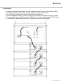
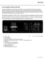
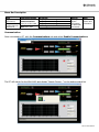
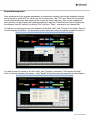
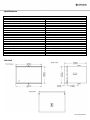
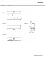
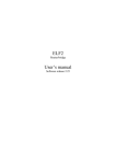
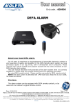
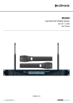
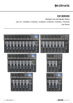
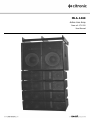
MLA-1460 Active Line Array Item ref: 171.220 User Manual Warning To prevent risk of fire or electric shock, do not expose any of the components to rain or moisture. If liquids are spilled on the amplifier panel, stop using immediately, allow unit to dry out and have checked by qualified personnel before further use. Avoid impact or dropping of the cabinets. No user serviceable parts inside – Do not open the case – refer all servicing to qualified service personnel. Safety Ensure all fixings are secure and adequate for supporting the weight of the MLA-1460 Ensure that the power cord is in good condition and adequate for the power rating Check for correct mains voltage and condition of IEC lead before connecting to power outlet Ensure speaker link leads are good condition with no short connections or damaged plugs Connect no more than 4 mid-top array cabinets to one active sub unit Avoid constant overload of the unit (indicated by constant lighting of the PEAK LED) Do not allow any foreign objects to enter the case or through the speaker grilles In case of failure of the MLA-1460, disconnect from the mains and check fuse. If fault repeats, refer to qualified service personnel Placement Keep amplifier panel out of direct sunlight and away from heat sources Avoid damp or dusty environments Ensure that the MLA-1460 is not positioned in a manner that may cause injury Ensure adequate access to controls and connections Cleaning Use a soft cloth with a neutral detergent to clean the casing as required Use a vacuum cleaner to clear ventilation grilles of any dust or debris build-ups Do not use strong solvents for cleaning the unit 171.220 User Manual Introduction Thank you for choosing the Citronic MLA-1460 active line array system. This self-contained unit can operate independently or as part of a larger system to provide accurate, full-range sound reproduction for applications as diverse as theatre, conference, live music venues and houses of worship. Please read and follow the instructions in this manual to achieve the best results and avoid damage through incorrect usage. Description The MLA-1460 is a self-contained active speaker system which combines an active 2 x 12” subwoofer with a group of 4 arrayed mid-top cabinets. The power amplifier section is housed in the subwoofer unit which, in turn, is linked to power the 4 mid-top cabinets. Each mid-top cabinet houses a pair of 6” low-mid drivers, single 6” high-mid driver and a precision ribbon tweeter for high frequencies and is engineered to provide a focused vertical output with a very wide dispersion for maximum horizontal coverage The input signal is fed via a digitally controlled EQ and dynamics processor to maximize efficiency in the system and enable frequency adjustment to tailor the output to suit the venue or application. Connection to a PC gives access to the DSP processor using the supplied software CDROM, allowing bespoke programming of the response and tone characteristics of the sub and array. Various installation methods are possible with the custom-designed mounting/flying frame, depending upon the building or surroundings and can be combined to provide modular arrays or multi-point sound reinforcement for larger areas. Components Due to the size of the components, the MLA-1460 is supplied in 6 individual cartons Please check that you have all 6 cartons and check the contents when opening the packaging. If any components are missing or damaged, contact your dealer immediately. The package should contain... Cartons 1, 2, 3, and 4 are passive line-array mid-top cabinets Carton 5 is the active subwoofer unit Carton 6 is the mounting/flying frame Also included should be the following Packet of fixing hardware PC Software CDROM Mains lead RS-232 cable USB cable 4 x Speaker link leads 171.220 User Manual Assembly The MLA-1460 may be assembled as a single vertically flown array, inverted as a floor-standing stack or combined into a multiple array. Assembly for standard flown orientation is shown below. 1. Secure the 4 U-rings to the flying frame. Each must be securely fixed using the appropriate hardware to ensure that there is no movement of the fixing or possibility of becoming unfastened through movement or vibration and should be suspended from a permanent fixing in the ceiling which is adequate for holding the weight of the complete line-array. 2. Securely attach the flying frame to the upper sub by connecting the M8 locknuts through the sub pulling plate at the front edge and connecting the array bracket on top of the sub to the central brace of the flying frame. 3. To connect an array cabinet underneath the sub cabinet, detach the ball-catch bolt from the front pulling plate and align with the bottom of the sub pulling plate on each side and replace the bolt through both. 4. Connect the Passive-Active Link bracket from the bottom of the sub cabinet to the rear of the topmost array cabinet. 5. Connect further array brackets below via the front pulling plates and connect at the rear with rear angle adjustment brackets (Angle adjustment is explained in the “Installation” section) 6. Assemble the array as shown below 171.220 User Manual Installation Single Flown Array For standard single flown array, installation is executed using 4 eyebolts attached to each corner of the flying frame. Fixings should be the strongest possible type for the substrate or ceiling supports to ensure a fail-safe installation. Suspension via wire rope or steel cables, each with a breaking strain of no less than 400kg is recommended per single line-array system. In some situations, it may be easier to suspend the sub unit first and then assemble line-array speakers below it, ensuring that the weight of each is adequately supported before securing to the array. Once assembled, the line-array can be curved to address the listening field by selecting various angle points on the rear angle adjustment brackets provided. The angle chosen depends largely upon the distance from the audience and the acoustic environment but should be adjusted so that each array speaker unit is vertically focused to evenly distribute the output across the listening field. Each Passive Back Link bracket has numbered lines for tilt in degrees. Whilst supporting the weight of the passive speaker, use these lines to align the correct fastening hole for the degree of tilt required for each component in the array. 171.220 User Manual Multiple Flown Array For multiple flown line-array, installation is similar to that of a single array with sub cabinets coupled together and passive units all flown in a single, longer array. With the uppermost sub unit attached to its flying frame, secure the 4 eyebolts for flying the array. Subsequent sub units can be attached underneath the topmost sub cabinet by connecting together the front pulling plates and the upper and lower array brackets. Connection of passive units from the bottom sub unit is executed in the same way as for a single line array, with each group of 4 passive units linked in a single line-array. Split Array The flying frame can also mount directly to the mid-top array cabinets via the front edge pulling plates and connecting the Passive – Active link directly from the rear of the topmost array speaker to the centre brace of the flying frame. Sub units can then be floor-standing and linked to 4 array cabinets each with longer cables Floor-standing Stack Where flying or ceiling mounting is not possible, it may be useful to arrange the MLA-1460 as a free-standing stack on the floor or on a stage. In this orientation, the sub unit sits on its flying frame on the floor and the passive units are splayed upwards above the sub unit. Prior to assembly, do not attach the 4 eyebolts to the flying frame. If the frame is likely to damage the floor surface, protect with rubber or other scratch-resistant material, or it may be preferred to mount the frame on castors for portability. Assemble passive units above the sub in the same manner as for a standard flown array shown above but inverted. Splayed angle adjustment may be used for venues with raised rear seating areas (e.g. theatres) 171.220 User Manual Connection Using the supplied speaker leads, connect 4 passive units to one sub unit as shown below. For multiple arrays, connect each group of 4 passive units to one sub unit. No more than 4 passive units may be connected to a single sub. Use the supplied IEC lead to connect to mains, ensuring correct voltage and power capacity Connect signal input via XLR (connect to LINE input – not to be confused with RS-485 input) To continue the signal onto further units, connect from the XLR LINE output 171.220 User Manual Active Amplifier Module with DSP The internal amplifier in the sub unit is optimized for use in conjunction with the 4 passive array speakers with built-in stepless variable fan cooling, overload protection and short-circuit protection. The rear panel features a power switch and single rotary volume control with PEAK LED. If this LED lights more than momentarily, the amplifier is liable to clip and the volume control should be reduced until the PEAK LED lights only for an instant each time. Input signal is processed via a DSP circuit for dynamics and EQ control, helping to protect the system and tailor the tonal response to the venue or particular application. A CDROM is included containing PC editing software for the MLA-1460 processor section. Connection to a PC can be made using USB, RS-232 or RS-485). See “Software Application Guide” for further information. 1. Power switch 2. IEC mains inlet 3. Mains fuse (replace only with approved type) 4. Speaker output connectors (pin 1+ hot, pin 1- cold) parallel linked 5. USB port 6. RS-232 port (9-pin D connector) 7. RS-485 input/output (digital XLR) 8. Rotary VOLUME control 9. PEAK LED indicator 10. LINE signal input/output (XLR) 171.220 User Manual Software Application Guide The MLA-1460 is supplied with a CDROM containing software. This software is also available for download from www.avsl-citronic.com/product/171.227UK System Requirements PC running Microsoft Windows XP or above. Display resolution 1024 x 768 or above USB or RS-232 port Connection to PC Connect directly to PC via USB using the supplied cable. The PC will find a “new device”, prompting the computer to look for driver software. The driver file is included on the CDROM (Browse to the “Driver” directory) If USB connection is not available, serial port link can be made from the RS-232 input on the rear panel using the supplied D-connector lead, again requiring driver installation from CDROM For PCs with an RS-485 interface using XLR connection, this can be used to connect from the PC to the MLA-1460 and passed from one MLA-1460 to another using the RS-485 output connector Software Operation Install the software (Active Speaker Controller.exe) from CDROM or download and run from the start menu or desktop shortcut. The user interface window will appear as shown below. 171.220 User Manual Menu Bar Description File Communications Program Device Help Open files from PC memory Save current configuration as a file to PC Enable or Disable Communications from PC to MLA-1460 Configure Serial Port to be used Display Current Program No Display Current Program Name Display Current Program Info List Program & Recall Save as Current Program in Device Modify device information (if MLA-1460 connected) Software version and information Communication Once connected to PC, click the Communications tab and select Enable Communications The PC will search for the MLA-1460 and display “Search Device…” on the bottom status bar 171.220 User Manual Once the MLA-1460 device is detected, a Device Select window will appear as shown here. Connected devices are listed on the left, showing the ID number. The current selected device ID number is displayed on the left-hand side. In multiple array setups, each must be allocated an individual ID number if they are to be controlled separately. To load the current internal program from the MLA-1460 into the software for editing, select “Upload Program Data From Device”. If the program currently held in the software is to be loaded into the MLA-1460, select “Download Program Data To Device” Select the required device by clicking on it on the right-hand side of the window and click “Connect” The current program status will populate the control window as shown below. 171.220 User Manual Signal Processing Functions The upper half of the control window shows a signal flow chart comprising various function buttons. Clicking on any of these buttons opens the parameters on the right side of the frequency chart which can be adjusted via further buttons and drop-down menus. INPUT PEQ 1 + 2 (2 x Parametric Equalizer) LEVEL HIGH HPF (High cabinets high-pass filter) HIGH LPF (High cabinets low-pass filter) LOW HPF (Sub cabinets high-pass filter) LOW LPF (Sub cabinets low-pass filter) HIGH OUTPUT PEQ 1-6 (High cabinets 6-band Parametric Equalizer) LOW OUTPUT PEQ 1-6 (Sub cabinets 6-band Parametric Equalizer) HIGH OUTPUT LEVEL (High cabinets output level) LOW OUTPUT LEVEL (Sub cabinets output level) COMPRESSION & LIMIT (Overall dynamics compression and limiting) HIGH DELAY (High cabinets time delay) LOW DELAY (Sub cabinets time delay) Filter Type: Peaking, Bandpass, Hi Shelf, Lo Shelf and Notch Frequency: 20Hz – 20kHz Bandwidth: 0.31 – 19.4 Octave Level: -12 – +12dB Level: -90 – +12dB Filter Type: 3 x Butterworth, 3 x Bessel filter slopes Frequency: Off, 20Hz-20kHz Filter Type: 3 x Butterworth, 3 x Bessel filter slopes Frequency: 20Hz-20kHz, Off Filter Type: 3 x Butterworth, 3 x Bessel filter slopes Frequency: Off, 20Hz-20kHz Filter Type: 3 x Butterworth, 3 x Bessel filter slopes Frequency: 20Hz-20kHz, Off Filter Type: Peaking, Bandpass, Hi Shelf, Lo Shelf and Notch Frequency: 20Hz – 20kHz Bandwidth: 0.31 – 19.4 Octave Level: -12 – +12dB Filter Type: Peaking, Bandpass, Hi Shelf, Lo Shelf and Notch Frequency: 20Hz – 20kHz Bandwidth: 0.31 – 19.4 Octave Level: -12 – +12dB Phase: Normal, inverse Level: -90 – +12dB Phase: Normal, inverse Level: -90 – +12dB Threshold: -49.5dB – 0.0dB Ratio: 1:1 – Infinity (brick wall limit) RMS Time: 0.01msec – 15sec Release Time: 0.01msec – 15sec Attack Time: 0.01msec – 15sec ms (milliseconds) 0 – 21.2292ms (corresponding distance in metres and ft/inches displayed) ms (milliseconds) 0 – 21.2292ms (corresponding distance in metres and ft/inches displayed) Adjustment of the above parameters is represented by corresponding changes on the frequency curve display. Combined equalization curves are shown on the EQ page and combined crossover curves are shown on the HPF/LPF page. 171.220 User Manual Program Management Once adjustment of the program parameters is complete as required, the current displayed settings can be stored as a file to PC for future use. On the menu bar, click “File” and “Save as” and browse to the preferred directory and name the file to save for future reference. This can be repeated for many versions of the program with different settings if required. These files can later be loaded into the software from PC memory by clicking “File” and then “Open”, browsing to the relevant file. To load the current program from the software to the MLA-1460, click “Program” and select “Save As Current Program In Device”. The drop-down menu offers the choice of program numbers to save to. To recall program(s) stored in the MLA-1460, click “Program” and select “List Program & Recall”. A list of internal programs will appear – click “Recall” to load the required program into the software. 171.220 User Manual Device Information For each MLA-1460 connected to the PC, the ID number and Device Name can be edited from the software editor. Click on the “Device” tab and select “Edit Current Device Information”. Note: Device ID is limited from 1 to 10, allowing up to 10 devices to be addressed separately connected in a group via RS-485 to the PC. Device name is limited to 14 ASCII characters. Program Name To change the current program name, click on the “Program” tab and select “Edit Current Program Name” and type in the new program name. 171.220 User Manual Disconnecting If it is decided not to save the edited program to the MLA-1460, click “Communications” tab and select “Disable Communications” and the MLA-1460 internal program will remain unchanged and can now be disconnected from the PC 171.220 User Manual Technical Information Frequency Response & Impedance Graph – Sub Cabinet Frequency Response & Impedance Graph – Mid-top Array Cabinet 171.220 User Manual Specifications Sub Unit 230Vac 50/60Hz (IEC) 45Hz – 300Hz 35Hz – 600Hz 92dB 122dB/128dB (PEAK) 900Wrms 2 x 300mm (12”) 730 x 630 x 508mm 55kg Mid-top Array Cabinet Impedance (each) 8Ω Frequency range (-3dB) 50Hz – 20kHz Frequency range (-10dB) 40Hz – 20kHz Sensitivity (1W/1m) 95dB Max SPL 116dB/122dB (PEAK) Max constant power output from sub unit (each) 140Wrms Low frequency drivers 2 x 165mm (6.5”) Mid frequency driver 1 x 165mm (6.5”) High frequency driver Wide dispersion ribbon tweeter Dimensions (each) 730 x 363 x 174mm Weight (each) 19kg Power supply Frequency range (-3dB) Frequency range (-10dB) Sensitivity (1W/1m) Max SPL Max constant power output Sub drivers Dimensions Weight Sub Unit 171.220 User Manual Mid-top Array Cabinet Errors and omissions excepted. Copyright© 2012. AVSL Group Ltd. 171.220 User Manual