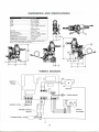
1
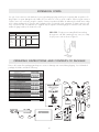
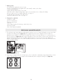
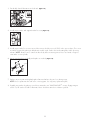
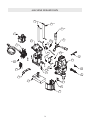
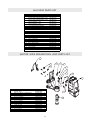
Slugger Holemaker II ® Slugger® Portable Magnetic Drilling Machine OPERATOR’S MANUAL WARNING! before use, be sure everyone using this machine reads and understands all safety and operating instructions in this manual. EYE PROTECTION REQUIRED HEARING PROTECTION REQUIRED NEVER PLACE FINGERS NEAR CUTTING AREA OR MACHINE ARBOR LINE VOLTAGE PRESENT BEWARE OF ROTATING MACHINE PARTS United States Patent #5,415,503 Other patents pending MODEL #USA200 (120V) OR #USA200-2 (240V) MODEL #USA200 (120V) OR #USA200-2 (220V) Serial #Date of Purchase Slugger® Portable Magnetic Drilling Machine Congratulations on your purchase of a Slugger® portable magnetic drilling machine. Slugger® drilling machines are designed to deliver fast, efficient hole drilling performance in portable applications. Please take a moment to complete and mail your product warranty registration card. Doing so will validate your machine’s warranty period and ensure prompt service if needed. Thank you for selecting a Slugger® product from Jancy Engineering Inc.™ table of contents Important Safety Instructions . . . . . . . . . . . . . . . . . . . . . . . . . . . . . . . . . . 3-4 Special Instructions, Grounding Instructions . . . . . . . . . . . . . . . . . . . . . . . . . 5 Extension Cords, Operating Instructions And Contents of Package . . . . . . . . . . 6 Getting Started, Before You Drill, Before The Cut . . . . . . . . . . . . . . . . . . . . 7-8 Ready To Make The Cut . . . . . . . . . . . . . . . . . . . . . . . . . . . . . . . . . . . . . 8 After The Cut, Basic Troubleshooting . . . . . . . . . . . . . . . . . . . . . . . . . . . . 9-10 Regular Maintenance . . . . . . . . . . . . . . . . . . . . . . . . . . . . . . . . . . . . . 10-11 Machine Breakdown . . . . . . . . . . . . . . . . . . . . . . . . . . . . . . . . . . . . . . . 12 Machine Parts List, Motor Slide Breakdown And Parts List . . . . . . . . . . . . . . . 13 Motor Breakdown . . . . . . . . . . . . . . . . . . . . . . . . . . . . . . . . . . . . . . . . . 14 Motor Parts List, Panel Breakdown And Parts List . . . . . . . . . . . . . . . . . . . . 15 Arbor Breakdown And Parts List . . . . . . . . . . . . . . . . . . . . . . . . . . . . . . . . 16 Arbor Support Breakdown And Parts List . . . . . . . . . . . . . . . . . . . . . . . . . . 16 Frame Breakdown And Parts List . . . . . . . . . . . . . . . . . . . . . . . . . . . . . . . 17 Frame Sub-Assembly Breakdown And Parts List . . . . . . . . . . . . . . . . . . . . . . 18 Dimensions And Specifications, Wiring Diagram . . . . . . . . . . . . . . . . . . . . 19 limited warranty Jancy Engineering Inc.™ will, within one (1) year from the original date of purchase, repair or replace any goods found to be defective in materials or workmanship, provided the product warranty registration card has been returned to Jancy Engineering Inc.™ within thirty (30) days of purchase date. This warranty is void if the item has been damaged by acci dent, neglect, improper service or other causes not arising out of defects in materials or workmanship. This warranty does not apply to machines and/or components which have been altered, changed, or modified in any way, or subjected to use beyond recommended capacities and specifications. Electrical components are subject to respective manufacturers’ warranties. All goods returned defective shall be returned prepaid freight to Jancy, which shall be the buyer’s sole and exclusive remedy for defective goods. In no event shall Jancy Engineering be liable for loss or damage resulting directly or indirectly from the use of merchandise or from any other cause. Jancy Engineering is not liable for any costs incurred on such goods or consequential damages. No officer, employee or agent of Jancy is authorized to make oral representations of fitness or to waive any of the foregoing terms of sale and none shall be binding on Jancy. ™ JANCY ENGINEERING INC.™ RESERVES THE RIGHT TO MAKE IMPROVEMENTS AND MODIFICATIONS TO DESIGN WITHOUT PRIOR NOTICE. 2 important safety instructions WARNING! WARNING Read all safety warnings and all instructions. Failure to follow the warnings and instructions may result in electric shock, fire and/or serious injury. Save all warnings and instructions for future reference. The term "power tool" in the warnings refers to your mains-operated (corded) power tool or battery-operated (cordless) power tool. 1. Work Area Safety a)Keep work area clean and well lit. Cluttered or dark areas invite accidents. b)Do not operate power tools in explosive atmospheres, such as in the presence of flammable liquids, gases or dust. Power tools create sparks which may ignite the dust or fumes. c)Keep children and bystanders away while operating a power tool. Distractions can cause you to lose control. d)Secure work. Use clamps or a vise to hold work. It’s safer than using your hand and it frees both hands to operate tool. 2. Electrical safety a)Power tool plugs must match the outlet. Never modify the plug in any way. Do not use any adapter plugs with earthed (grounded) power tools. Unmodified plugs and matching outlets will reduce risk of electric shock. b)Avoid body contact with earthed or grounded surfaces such as pipes, radiators, ranges and refrigerators. There is an increased risk of electric shock if your body is earthed or grounded. c)Do not expose power tools to rain or wet conditions. Water entering a power tool will increase the risk of electric shock. d)Do not abuse the cord. Never use the cord for carrying, pulling or unplugging the power tool. Keep cord away from heat, oil, sharp edges or moving parts. Damaged or entangled cords increase the risk of electric shock. e)When operating a power tool outdoors, use an extension cord suitable for outdoor use. Use of a cord suitable for outdoor use reduces the risk of electric shock. f) If operating a power tool in a damp location is unavoidable, use a ground fault circuit interrupter (GFCI) or residual current device (RCD) protected supply. Use of a GFCI ar RCD reduces the risk of electric shock. 3. Personal safety a)Stay alert, watch what you are doing and use common sense when operating a power tool. Do not use a power tool while you are tired or under the influence of drugs, alcohol or medication. A moment of inattention while operating power tools may result in serious personal injury. b)Use personal protective equipment. Always wear eye protection. Protective equipment such as dust masks, non-skid safety shoes, hard hats or hearing protection used for appropriate conditions will reduce personal injuries. 3 important safety instructions c)Prevent unintentional starting. Ensure the switch is in the “OFF” position before connecting to power source and/or battery pack, picking up or carrying the tool. Carrying power tools with your finger on the switch or energizing power tools that have the switch on invites accidents. d)Remove any adjusting key or wrench before turning the power tool on. A wrench or key left attached to a rotating part of the power tool may result in personal injury. e)Do not overreach. Keep proper footing and balance at all times. This enables better control of the power tool in unexpected situations. f) Dress properly. Do not wear loose clothing or jewelry. Keep your hair, clothing and gloves away from moving parts. Loose clothes, jewelry or long hair can be caught in moving parts. g)If devices are provided for the connection of dust extraction and collection facilities, ensure these are connected and properly used. Use of dust collection can reduce dust-related hazards. 4. Power tool use and care a)Do not force the power tool. Use the correct power tool for your application. The correct power tool will do the job better and safer at the rate for which it was designed. b)Do not use the power tool if the switch does not turn it on and off. Any power tool that cannot be controlled with the switch is dangerous and must be repaired. c)Disconnect the plug from the power source and/or the battery pack from the power tool before making any adjustments, changing accessories or storing power tools. Such preventative safety measures reduce the risk of starting the power tool accidentally. d)Store idle power tools out of the reach of children and do not allow persons unfamiliar with the power tool or these instructions to operate power tool. Power tools are dangerous in the hands of untrained users. e)Maintain power tools. Check for misalignment or binding of moving parts, breakage of parts and any other condition that may affect the power tool’s operation. If damaged, have the power tool repaired before use. Many accidents are caused by poorly maintained power tools. f) Keep cutting tools sharp and clean. Properly maintained cutting tools with sharp cutting edges are less likely to bind and are easier to control. g)Use the power tool, accessories and tools etc. in accordance with these instructions, taking into account the working conditions and the work to be performed. Use of the power tool for operations different from those intended could result in a hazardous situation. h) Check for damaged parts. Before further use of the tool, a guard or other part that is damaged should be carefully checked to determine that it will operate properly and perform its intended function. Check alignment of moving parts, binding of parts, breakage of parts, mounting and any other conditions that may affect its operation. A guard or other part that is damaged should be properly repaired or replaced by an authorized service center. 5. Service a)Have your power tool serviced by a qualified repair person using only identical replacement parts. This will ensure that the safety of the power tool is maintained. 4 special instructions 1. If you require an additional manual, please contact Jancy Engineering at (563) 391-1300 for a FREE copy. 2. Never place hands, fingers, gloves or clothing near cutting area or rotating machine parts. 3. Always disconnect machine from power source before changing cutters, clearing chips, refilling lubricant or performing adjustments. 4. Keep all safety features functioning and working properly. 5. Never wear loose clothing, gloves or jewelry when working near cutting area or rotating machine parts. 6. Always use eye and hearing protection. 7. Always use safety strap and chip guard provided with machine. 8. Always use proper tooling. Keep cutters securely fastened. 9. Do not use dull or broken cutters. 10.Do not use Slugger® drilling machines on surfaces or materials being welded. Doing so can damage the machine’s electrical components. 11.Beware of slugs ejected at end of cut. They become HOT during the cut. 12.Magnet will not hold properly on thin materials or rough and dirty surfaces. 13.Keep bottom of magnet burr free and clear of chips and debris. 14.To reduce the risk of electrical shock, do not use machine in wet or damp areas. 15.Do not remove or alter electrical components. Use only authorized service centers for repairs. WARNING! do not operate machine if warning and /or instruction Patent # 5,415,503 Other patents pending. TM SMART MAGNET CIRCUITRY. labels are missing or damaged. • Read and follow operators manual thoroughly. If you can not locate your operator’s manual, call Jancy Engineering Inc. at 563.391.1300 for a free copy. • Always stop machine completely and disconnect from power source before changing cutters, performing adjustments or servicing. • Do not use altered, dull or broken cutters. • Never wear loose clothing or gloves when working near cutting area or machine arbor. • Always use provided safety strap and chip guard. • Use proper tooling. Keep cutters securely fastened. • Magnet will not hold properly on thin materials, rough or dirty surfaces. Keep magnet free of chips and debris. • Keep all safety features functioning and working properly. • Use only authorised service centers for repairs. contact jancy engineering for replacement labels. Patent # 5,415,503 Made in USA grounding instructions WARNING! Improperly connecting the grounding wire can result in the risk of electrical shock. Check with a qualified electrician if you are in doubt as to whether the outlet is properly grounded. Do not modify the plug provided with tool. Never remove the grounding prong from the plug. If the cord or plug is damaged, have it repaired before using. If the plug will not fit the outlet, have a proper outlet installed by a qualified electrician. The Holemaker II must be plugged into an appropriate outlet, properly installed and grounded in accordance with all codes and ordinances. The plug and outlet should look like those in Figure A. WARNING! do not use Slugger® drilling machines on surfaces or materials being welded. doing so can result in personal injury and /or damage to the Slugger® drilling machine. 5 WARNING - To reduce the risk of injury, user must read instruction manual. AVERTISSEMENT - Pour réduire les risques de blessures, l'utilisateur doit lire le manuel d'instruction. ADVERTENCIA - Para reducir el riesgo de lesiones, el usuario debe leer el manual de instrucciones. WARNING - Always wear eye protection. ATTENTION - Toujours porter des lunettes de protection. ADVERTENCIA - Siempre use protección para los ojos. WARNING - Line voltage present. AVERTISSEMENT - Ligne de tension présente. ADVERTENCIA - Voltaje de línea presente. ® ® MODEL: VOLTAGE AMPERAGE WATTS RPM USA200 120V ~ 50/60 HZ 11.5A 1380W 450 RPM N0 CAUTION: FOLLOW SAFETY PROCEDURES! CAUTION - Always wear hearing protection. ATTENTION - Toujours porter des protections auditives. PRECAUCIÓN - Siempre use protección para los oídos. CAUTION - Beware of ejected slug at end of cut. MISE EN GARDE - Méfiez-vous des pieces de métal éjectées à la fin de la coupe. PRECAUCIÓN - Tenga cuidado con el taquete expulsado al final del corte. 2735 HICKORY GROVE RD. - DAVENPORT, IA 52804 563-391-1300 - WWW.JANCY.COM SN: 021C-01001 extension cords Use only 3-wire extension cords that have 3-prong grounding-type plugs and 3-pole receptacles that accept the tool’s plug. Replace or repair damaged cords. Make sure your extension cord is in good condition. When using an extension cord, be sure to use one heavy enough to carry the current your product will draw. An undersized cord will cause a drop in line voltage resulting in loss of power and overheating. Jancy recommends using a minimum 12 gauge extension cord not to exceed 100 feet. The table below is supplied only as a guide to minimum gauge for extension cords, where the smaller the gauge number, the heavier the cord. DRIP LOOP: To help prevent cutting fluids from traveling along power cord and contacting power source, tie a drip loop in power cord as shown in Figure B. minimum gauge for extension cords volts total length of cord in feet 120V 240V 0-25 0-50 26-50 51-100 51-100 101-150 101-200 201-300 18 18 16 14 16 16 16 12 16 14 14 amperage 0-6 6-10 10-12 12-16 14 12 12 not recommended recommended wire gauge note: jancy recommends using a minimum sion cord not to exceed 100 feet. 12 gauge exten- Fig. B operating instructions and contents of package Remove all contents from packaging and inspect to ensure no damage was incurred during shipping. Your Holemaker II package should also include the following: item 1 2 3 4 5 6 7 8 9 10 11 12 13 14 15 16 17 18 19 description part # qty 32208142020 OPERATOR'S MANUAL U14202 1 PRODUCT DVD LIT032 1 34198142400 32298141050 WARRANTY CARD 0070342 1 3/16" PILOT, 1" DEPTH OF CUT 63134998001 16001 1 3/16" PILOT, 2" DEPTH OF CUT 65134998002 16002 1 1/4" PILOT, 1" DEPTH OF CUT 65134998003 16003 1 1/4" PILOT, 2" DEPTH OF CUT 65134998004 16004 1 M10 X 8 FPSSS UH0900 2 43098709000 M8 X 8 FPSSS UH0804 2 43098708040 5MM T-HANDLE HEX WRENCH 62998780040 UH8004 1 4MM HEX WRENCH UH8002 1 62998780020 62998780010 3MM HEX WRENCH UH8001 1 8MM COMBINATION WRENCH62998780060 UH8006 1 64298130060 SUPPORT HANDLE U13006 1 SPOKE HANDLE U12100 3 64298121000 MAGNET WARNING NOTICE 34198142360 0107D0C 1 SHUNT (ATTACHED TO HANDLE) 30798753350 UH5335 1 SHUNT INSTRUCTIONS U14102 1 32298141020 SAFETY STRAP U11005 1 64298110050 1 2 8 9 Slugger Holemaker II ® 7 Slugger Portable Magnetic Drilling Machine OPERATOR’S MANUAL WARNING! BEFORE USE, BE SURE EVERYONE USING THIS MACHINE READS AND UNDERSTANDS 6 ALL SAFETY AND OPERATING INSTRUCTIONS IN THIS MANUAL. EYE PROTECTION REQUIRED HEARING PROTECTION REQUIRED NEVER PLACE FINGERS NEAR CUTTING AREA OR MACHINE ARBOR LINE VOLTAGE PRESENT BEWARE OF ROTATING MACHINE PARTS 5 United States Patent #5,415,503 Other patents pending 3 10 11 4 12 MODEL #USA200 (120V) OR #USA200-2 (220V) Serial # 15 Date of Purchase 13 17 16 19 18 6 14 getting started CAUTION! always disconnect Holemaker II from power source before making adjustments. Assemble three spoke handles to feed hub. NOTE: Feed hub assembly is mounted on right side of machine frame from factory. (Figure 1) If necessary, it can be mounted for left hand operation. To do so, loosen screw until hub assembly is free (the screw will remain in the hub), move to left side and reattach hub. Figure 1 what you should know before you drill 1.Type of material to be drilled, Brinnell or Rockwell hardness, material thickness and position should all be determined to ensure proper selection of Slugger® cutting tools, coolant and drilling time. 2.Material that has been flame cut may have become heat-treated and therefore difficult to drill. Avoid drilling near such areas whenever possible. 3.Drilling with the Holemaker II in horizontal positions requires a special lubrication for Slugger® cutters. Consult Jancy Engineering for details. 4.Our new Holemaker II incorporates state of the art design features such as our “SMART MAGNET ”® circuitry. This feature does not allow the motor to operate in unsafe magnetic holding conditions. Illuminated on/off switches indicate the existence of a sufficient magnetic field. If On/Off switches are not illuminated, there is not a proper magnetic field. When drilling materials under 3/8" thick, an additional steel plate may be required to achieve proper magnetic adhesion. 5.Remove any excessive mill scale or rust from surface to be drilled. Thin material, mill scale, rust, paint, existing holes, surface irregularities, coolant, chips and other factors could affect magnetic holding conditions. before the cut Table 1 1. Select correct pilot pin (Table 1) and place in cutter shank from the rear, align Pilot 16001 63134998001 flats on cutter shank with arbor body set screws, insert cutter in arbor body. 16002 63134998002 16003 63134998003 2. Tighten set screws securely on cutter shank flats. NOTE: Set screws should be 16004 63134998004 recessed in arbor body when tight. 3. The surface you are working on should be clean and flat, free from rust, scale, dirt and chips. 4. Place Slugger® machine on workpiece with pilot pin over the center of hole to be drilled. (Figure 2) Figure 2 5. Connect machine to power source. (Figure 3) 7 For Cutter 1" DOC, 1/2" (14MM) Dia and Smaller 2" DOC, 1/2" (14MM) Dia and Smaller 1" DOC, 9/16" (15MM) Dia and Larger 2" DOC, 9/16" (15MM) Dia and Larger Figure 3 before the cut (cont .) 6. Turn on coolant valve, located on left side of the frame. (Figure 4) Lower Slugger® cutter to surface of material to be cut. NOTE: Coolant flow starts when pilot pin contacts work surface. Coolant flow can be stopped by lifting pilot pin off work surface or moving the valve to the "off" position. OFF Figure 4 ON CAUTION! always use safety strap. failure to do so could result in personal injury and /or damage to the Slugger® drilling machine. 7. The safety strap must be securely fastened to machine and around work being drilled. Loop strap around work piece and connect strap ends by attaching to D-rings on drill. (Figure 5) NOTE: Safety strap is intended only to restrain the drill to the workpiece in the event of a power failure to the magnetic base. 8. Position chip guard toward work area before drilling. (Figure 6) Figure 5 Figure 6 ready to make the cut CAUTION! CLOSE CHIP GUARD AND LOWER TO WORK SURFACE. NOTE: IF ON/OFF SWITCHES ARE NOT ILLUMINATED, THERE IS NOT A PROPER MAGNETIC FIELD. 1. Move magnet switch to “ON” position. (Figure 7) Switch will illuminate to indicate power is present – magnetic base should be firmly secured to workpiece at this time. Thin materials may require an additional steel plate to achieve proper magnet adhesion. 2. Start drill motor by depressing green motor “ON” button. (Figure 8) 3. Using the feed handles, advance cutter into material until Slugger® cutter has established an external groove in the material. During the remainder of cut, apply smooth constant pressure without overloading motor. (Figure 9) NOTE: Slugger® cutters are designed for uninterrupted cutting. Chips are evacuated during the cut. Do not peck drill when using Slugger® cutters. Figure 7 CAUTION! if drill motor should stall or stop before a complete cut is made, always remove cutter from hole before attempting to restart motor. failure to do so could result in personal injury and/or damage to the Slugger® drilling machine. note: this Figure 8 machine’s standard unmodified circuitry will automatically shut the drill motor off if magnetic base is separated from its work surface. if your machine requires adjustment , contact jancy’s service department. Figure 9 8 after the cut CAUTION: THE SLUG WILL BE HOT AND HAVE SHARP EDGES. 1. After the Slugger® cutter has finished the cut, the “slug”, or uncut center portion of material, will be expelled when motor is returned to the full up position. (Figure 10) 2. Depress red motor “OFF” button. Wait until motor completely stops. (Figure 11) 3. Move magnet switch to “OFF” position when ready to release magnetic base from work surface. (Figure 12) 4. Residual magnetism may exist after magnet is turned off. Figure 10 Figure 11 Figure 12 basic troubleshooting 1. Magnetic base not holding securely • Material is too thin to engage magnet properly. • Surface of material being drilled must be free of chips, debris, rust and mill scale. • Size of cutter exceeds machine’s rated capacity. • Excessive downfeed pressure. • Check magnet face for unevenness, nicks and burrs. • Welding equipment connected to material being drilled. 2. Drill motor not running • Insufficient magnetic field, "Smart Magnet"® circuitry functioning properly. (See page 7) • Check motor cord. • Check magnet resistance. 3. Motor switches not illuminated • Insufficient magnetic field, "Smart Magnet"® circuitry functioning properly. (See page 7) • Check switches for functionality. 4. Drill motor running, arbor and spindle not turning • Possible sheared spindle key. 5. Motor slows when drilling • If an extension cord is being used, see page 6 for recommended wire gauges and cord lengths. • Excessive downfeed pressure during drilling cycle will cause motor to slow and overheat. • Cutting tool needs to be resharpened. 6. Slugs not ejecting from cutter • Lack of coolant causing slugs to expand in cutter bore. • Incorrect pilot pin being used. • Possible broken internal arbor parts. 9 7. Breaking cutters • Coolant must be supplied to interior of cutter. • Excessive feed pressure being applied when cutter initially contacts work surface. • Confirm material hardness. • Drilling stacked materials with incorrect cutter. • Dull cutters; dull or chipped cutting edges require excessive feed pressure, resulting in breakage. • Excessive arbor runout – see regular maintenance on page 10. • Possible bent motor spindle or worn arbor sleeve. • Improperly adjusted motor slide – see page 10. 8. Oversized or rough holes • Insufficient coolant. • Excessive feed pressure. • Excessive cutter runout. • Dull cutter. • Worn support bracket roller bearing or arbor body sleeve. • Bent motor spindle. • Motor slide improperly adjusted. regular maintenance 1. The rail system may require adjustment after machine has been in service. Using feed handles, position motor/slide assembly in the full up position. (Figure 13) Using supplied 3mm hex wrench, slightly turn the two M6 X 10 adjustment screws equally on each of the two guide rods clockwise to increase rail tension, or counterclockwise to decrease rail tension. (Figure 14) Again using feed handles, position motor/slide to down position and insure even adjustment throughout travel. Do not over tighten adjustment screws as excessive rail tension can damage the machine. Properly adjusted, the motor/slide assembly should have no side-to-side movement and will remain where positioned without drifting. 24 23 Figure 13 Figure 14 2. Keep bottom of magnet clean, free of chips, burrs, nicks, oil and other contaminants. Inspect magnet face to ensure surface is flat and square. A worn magnet surface dramatically reduces magnetic holding force. (Figure 15) NEW WORN Figure 15 10 3. Periodically clean & lubricate motor slide rails. (Figure 16) Figure 16 4. Visually inspect arbor, and support bracket for wear. (Figure 17) Figure 17 5. Visually inspect arbor for excessive runout. Arbor runout should not exceed .0035 inches per revolution. This is most accurately measured by placing a dial indicator needle inside of arbor bore and rotating arbor while observing indicator. NOTE: Always remove cutter from arbor body before measuring runout. Never use hands or fingers to rotate arbor or motor spindle. 6. Inspect motor brushes periodically and replace as needed. 20mm (Figure 18) 7.50mm Figure 18 7. Replace any worn parts and regularly tighten fasteners that have become loose during usage. NOTE: Never operate machine with worn or missing parts. Use only Jancy replacement parts. ® 8. Regularly test machine by placing on non-ferrous material to test "SMART MAGNET" circuitry. Engage magnet switch. On/off switches should not illuminate. Motor should not start when on button is pushed. 11 machine breakdown 4 10 4X 14 3X 7 1 13 22 21 5 24 19 4X 25 4X 16 3 8 18 11 10 9 20 4X 6 15 2 17 23 12 12 machine parts list ITEM DESCRIPTION 1 FRAME ASSEMBLY 2 MAGNET ASSEMBLY,120V,220V MOTOR AND SLIDE ASSEMBLY,120V 3 MOTOR AND SLIDE ASSEMBLY,120V 4 GUIDE ROD PANEL ASSEMBLY, 120V 5 PANEL ASSEMBLY, 220V 6 SUPPORT HANDLE 7 COOLANT BOTTLE ASSEMBLY 8 M3.5 X 10 CRPHMS - ETLW 9 1/4" LOCK WASHER 10 M6 X 20 SHCS 11 SHEET OF LABELS 12 GUARD ASSEMBLY 13 HUB ASSEMBLY 14 SPOKE HANDLE 15 SAFETY STRAP LINK 16 BRUSH AND CAP SET 17 M4 X 10 CRFHMS 18 MOTOR CORD COVER 19 M4 X 14 CRFHMS 20 BRASS BARB FITTING 21 COOLANT VALVE ASSEMBLY 22 M3 X 25 SHCS 23 M6 X 6 NTSSS 24 3/16" ID X 10" TUBING 25 RUBBER GROMMET PART # QTY 33298392040 1 33298492000 1 52298692130 1 52298692140 33298322020 2 30798592010 1 30798592030 64298130060 1 32198190050 1 43098703230 4 42498724020 4 43098706400 8 32298140030 1 64298160240 1 64298160160 1 64298121000 3 64298110040 1 52298691020 1 43098704080 2 33298331060 1 43098704260 4 31498761040 1 64298161120 1 43098703210 2 43098706030 1 31498760100 1 30798757120 1 motor slide breakdown and parts list 15 14 12 11 10 13 9 8 6 5 7 ITEM 1 2 3 4 5 6 7 8 9 10 11 12 13 14 15 DESCRIPTION MOTOR, 120V MOTOR, 240V RED MALE BULLET CONNECTOR ARBOR ASSEMBLY M5 X 14 DOWEL PIN M4 X 16 CRFHMS WIRE COVER SPACER M4 X 6 CRTHMS M4 LOCK WASHER M4 X 14 CRFHMS CORD CLAMP SLIDE ASSEMBLY 1/4" LOCK WASHER M6 X 16 SHCS MOTOR CORD ASSEMBLY QTY PART # 52298692010 1 52298692030 30798753090 2 33498292000 1 40298742020 2 43098704290 1 32498610020 1 42498726080 1 43098703980 1 42498720440 1 43098704260 1 32498610040 1 31342621154 1 4 42498724020 43098706240 4 30798591040 1 13 4 3 2 1 motor breakdown 4 5 3 19 2 1 20 6 2 15 22 25 26 21 7 3 29 4 8 23 9 27 10 28 24 26 15 30 31 29 11 32 12 33 13 34 14 35 15 36 37 16 38 17 11 18 14 11 motor parts list ITEM 1 2 3 4 5 6 7 8 9 10 11 12 13 14 15 16 17 18 19 20 21 22 23 24 25 26 27 28 29 30 31 32 33 34 35 36 37 38 DESCRIPTION MOTOR HOUSING BRUSH HOLDER CARBON BRUSH CARBON BRUSH CAP M5 X 5 CPSSS INTAKE LOUVER M4 LOCK WASHER M4 X 10 CRPHMS STRAIN BUSHING M5 X 50 CRPHMS M5 LOCK WASHER FIELD, 120 V FIELD, 230 V FIELD INSULATOR WAVE WASHER BALL BEARING ARMATURE, 120 V ARMATURE, 230 V BALL BEARING M5 X 20 CRPHMS GEAR BOX COVER GASKET EXTERNAL RETAINING RING SHAFT KEY OUTPUT GEAR EXTERNAL RETAINING RING SHAFT KEY EXTERNAL RETAINING RING INTERMEDIATE GEAR OUTPUT PINION GEAR BALL BEARING INTERMEDIATE PINION M5 X 12 DOWEL PIN GEAR BOX CASTING 1/4" LOCK WASHER M6 X 35 SHCS LIP SEAL BALL BEARING INTERNAL RETAINING RING MOTOR SPINDLE QTY PART # 31998631060 1 30798651050 2 30798651060 2 30798651080 2 43098705000 2 32498611020 1 42498720440 2 43098704200 2 30798757000 1 43098705600 2 42498720500 6 51298651030 1 51298651040 31998631040 1 42498726140 1 41798730200 4 53298651010 1 53298651020 41798730390 1 43098705440 4 31998631020 1 32498611000 1 42698740140 1 40298745020 1 33698681010 1 42698740170 1 40298745040 2 42698740120 3 33698681030 2 33698681020 1 41798730120 2 33698681040 1 40298742000 2 31998631010 1 42498724020 4 43098706580 4 40698763020 1 41798730450 1 42698741350 1 33498621000 1 panel breakdown and parts list 9 7 14 1 3 2 15 19 ITEM 1 2 3 4 5 6 7 8 9 10 11 12 13 14 15 16 17 18 19 20 DESCRIPTION PANEL PLATE PCB BOARD, 120V PCB BOARD, 220V PANEL LABEL RED OFF PUSH BUTTON SWITCH GREEN LIGHTED ROCKER MAG GREEN ON PUSH BUTTON SWITCH PANEL PLATE INSULATOR POWER CORD PCB AND WIRE HARNESS ASSEMBLY STRAIN RELIEF STRAIN RELIEF NUT RED TERMINAL CRIMP FEMALE PUSH-ON TERMINAL PANEL GASKET PANEL BOARD CABLE ASSEMBLY M4 X 10 DSPHMS M4 LOCK WASHER M4 NUT SWITCH GUARD SPACER QTY PART # 30798512000 1 30798550020 1 30798550030 32298142000 1 30798755040 1 30798755000 1 30798755020 1 30798511000 1 30798750000 1 30798550040 1 30798757040 1 30798757041 1 30798753260 1 30798753160 2 30798510020 1 30798591065 1 43098704180 1 42498720460 1 40298746040 1 32498520020 1 32498520040 1 15 20 4 6 16 17 18 13 12 11 10 5 8 arbor breakdown and parts list 1 ITEM 1 2 3 4 5 6 7 8 7 7 8 DESCRIPTION ARBOR SPRING ARBOR FLOATING PISTON RUBBER WASHER STEEL WASHER INTERNAL RETAINING RING M8 X 8 FPSSS M10 X 8 FPSSS QTY PART # 33498222100 1 30998744100 1 33498221060 1 42498726040 1 42498726060 1 42698741190 1 43098708040 2 43098709000 2 8 2 3 4 5 6 arbor support breakdown and parts list ITEM 1 2 3 4 5 6 7 8 DESCRIPTION SLIDE GUIDE ROD BUSHING GEAR RACK M4 X 10 SHCS ARBOR BUSHING LIP SEAL M5 X 20 SHCS M5 NUT QTY PART # 31998632020 1 33498622060 4 33698680040 1 43098704120 3 33498622000 1 40698763000 2 43098705420 4 42098746090 4 3X 2 4X 1 4 3 6 5 7 4X 8 6 16 4X frame breakdown and parts list 7 1 5 2 6 4 3 7 5 ITEM 1 2 3 4 5 6 7 8 DESCRIPTION FRAME AND HANDLE ASSEMBLY PINION SHAFT PINION GEAR KEY FLANGE BUSHING BUSH SHAFT ENCLOSURE EXTERNAL RETAINING RING QTY PART # 33298332000 1 33298320040 1 64298160120 1 40298745000 1 33298320080 2 33298320060 2 31498532000 1 42698740160 2 17 frame sub - assembly breakdown and parts list 5 2 3 4 2 2X 1 ITEM 1 2 3 4 5 DESCRIPTION FRAME M8 X 16 SHCS M4 X 10 BHSCS M4 LOCK WASHER HANDLE QTY PART # 33298332040 1 43098708100 2 43098704060 2 42498720440 2 33298330020 1 18 other available description USA5 120V USA5 240V USA101 120V USA101 240V 2 X 2 120V 2 X 2 240V 4 X 4 120V 4 X 4 240V MAGFORCE 120V MAGFORCE 240V Slugger model # max diameter 18066 2-3/8" 18080 2-3/8" USA101 1-1/2" USA101-2 1-1/2" 17980 2" 17982 2" 17985 4" 17987 4" 06920 1-5/8" 06921 1-5/8" ® drills depth capacity 3" 3" 2" 2" 2" 2" 3" 3" 2" 2" your distributor Tel · 563.391.1300 or Fax · 563.391.2323 2735 Hickory Grove Road · Davenport, Iowa 52804 email · [email protected] / web · jancy.com U14202 - Ver.4 © Jancy Engineering Inc.™ 07/11 01/11