1
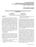
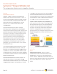
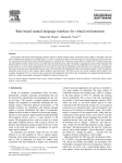
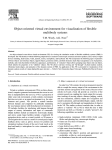
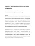
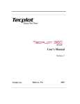
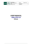
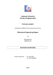
IVRESS/CFD Integrated Virtual Reality Toolkit for Effective Visualization of CFD Datasets in Virtual Environments EXECUTIVE SUMMARY A strategy for effective visualization of CFD datasets in virtual environments (VEs) is presented. The VE is driven by the object-oriented scene-graph-based IVRESS toolkit. The key elements of the proposed visualization strategy are: (a) strategic use of global and local visualization objects; (b) effective use of multimodal interfaces including hierarchical GUIs and naturallanguage voice commands; (c) a general efficient point search algorithm that allows constructing the visualization objects at interactive frame rates. The global visualization objects include arrays of stream lines/ribbons/volumes, colored/contoured surfaces; volume arrows; iso-surfaces; vortex cores and boundary layer visualization objects (including surfacerestricted streamlines and separation/attachment lines). The local visualization objects include: stream lines/ribbons/volumes probes; colored/contoured surfaces; elevation surfaces; surface arrows; local iso-surfaces, crosssection line probes, and 2D graphs. Primitive response quantities such as pressure, velocity and density as well as derived quantities such as Mach number, pressure gradient, and shock waves can be used in all visualizations. An optional web browser plug-in makes IVRESS/CFD fully web-enabled. 1. INTRODUCTION Virtual environments (VEs) are three-dimensional, computergenerated environments that can be interactively viewed and manipulated by the user in real-time. VEs provide a natural interface between humans and computers by artificially mimicking the way humans view and interact with their physical environment. The VE output devices used here include an immersive stereoscopic display and stereo speakers. The input devices include: • • • • • Hand-held devices for navigation, including: wand, joystick, 3D mouse, 2D mouse, touch pad. Haptic feedback devices such as gloves. Wireless tablet PC, hand-held computer (PDA), or keyboard. Devices for position and orientation tracking of parts of the user’s body (such as the head and hands). Microphone for voice commands. Computational-fluid dynamics (CFD) codes are widely used to calculate the flow fields for many practical engineering systems such as aerospace vehicles (airplanes and space launch/reentry vehicles), ground transportation vehicles (cars, trucks, and trains), maritime vehicles (ships and submarines), and turbines. The CFD results can be used to improve the design and performance of those engineering systems. However, deriving useful information from the complex spatial flow fields generated by the CFD codes requires an effective visualization strategy that can help users quickly and accurately extract the useful design information from the CFD results. VEs can play a key role in that visualization strategy because they allow the users to view and manipulate the spatial flow field in a natural intuitive spatial environment. Currently, visualization of CFD results in immersive VE facilities is an active research and development area, stemming from two main directions: research on VEs and research on CFD visualization. A key requirement for VEs is that the visual frame rate and interaction response rate of the VE must be at least 10 Hz in order to provide close-to-real world coupled display and interactivity to the user. Note that some visualization strategies and algorithms used in CFD visualization software preclude this requirement. On the other, hand VE toolkits do not include or lack the detailed menu interface for displaying and fine tuning the full set of visualization capabilities of CFD visualization software. IVRESS/CFD fills this gap. In reference [1] the IVRESS VE toolkit was used for visualization of CFD results. Most types of CFD visualization objects were incorporated, including: stream objects (lines, surface-restricted lines, ribbons, and volumes) with arrow/particle animation; colored surfaces; elevation surfaces; surface arrows; global and local iso-surfaces; vortex cores; and separation/attachment surfaces and lines. In the present white paper, a rational strategy for visualization of CFD results in VEs is presented. The strategy minimizes the tedium of interacting with 3D menus and probes and maximizes the useful information that can be quickly and easily displayed to the user. Key elements of the proposed strategy are: - Use of both global and local visualization objects. Each global and local visualization object is carefully designed to allow easy change of the object parameters in order to reduce the visual clutter. Also, global visualization objects that extract the critical features from the flow field are implemented. These include vortex cores, surface- 2002 Advanced Science and Automation Corporation 1 restricted streamlines and separation/attachment lines. These visualization objects “summarize” the flow field by at least 2-3 orders of magnitude. - - Effective use of multimodal interfaces that can be used change the visualization objects parameters. Two types of interfaces are used: hierarchical graphical menu and a voice natural-language interface (NLI). The menu can be used on: an on-screen 3D window, a hand-held wireless tablet PC, or a hand-held wireless PDA (Personal Digital Assistant). The Tablet PC and PDA are connected to the VE display computer using wireless LAN. The graphical menu includes the following graphical widgets: sliders, text boxes, option buttons, and check boxes. The use of a Tablet PC or PDA eliminates the tedium of moving the entire arm to access the menu. In addition, it also eliminates the need to display the on-screen menu, thus maximizing the display area available for the CFD results and reducing visual clutter by moving the menu out of the view field. The NLI is a hierarchical rule-based expert system [2]. It allows modifying the parameters of objects using near-natural language speech. The NLI rule hierarchy is the same as the menu hierarchy thus once the user learns the menu, s/he can use the NLI. The NLI uses a wireless microphone and runs on a remote computer that is connected to the VE computer via LAN. A general efficient point search algorithm that allows constructing the visualization objects at interactive frame rates. This white paper is divided into five sections. In Section 2 an overview of the present point search algorithm with some brief background is presented. In Section 3, the multimodal interfaces used, including the hierarchical menu and NLI, are described. In Section 4, a visualization case study is presented. In the case study the local and global visualization objects as well as objects for visualization of the computational grid are described. Concluding remarks are offered in Section 5. The CFD visualization VE was constructed using the IVRESS toolkit [3]. 2. POINT SEARCH ALGORITHM algorithm, searching for the next point starts from the previous point found. Since the next search point is likely to be found in the neighborhood of the previous point for most visualization objects this local search step reduces the theoretical search cost to well below log(N). In the present algorithm, all grids are converted to a uniform internal representation, which is an unstructured mesh with optional disabled nodes. This enables use of all commonly used types of grids, including multi-block structured, multi-block overlapping structured, and unstructured CFD grids, using the same algorithm. At the lowest group level - the element level - an inverse trilinear interpolation is used to make a final determination about the exact location of the point in the element. The present point search algorithm was implemented in a support object class in IVRESS called “VolumeSearch.” All Other visualization objects can simply refer an object of this class. This object will then perform all required point searches. 3. MULTIMODAL INTERFACES Multimodal interfaces can be defined as: “human-machine interfaces that aim to improve the efficiency, effectiveness and naturalness of human machine-interaction [4].” In the present white paper, the following output modalities were used: - - The following input modalities were used: - An essential step in real-time visualization of spatial fields is locating an arbitrary point in the computational grid (i.e., finding the finite element where a given point lies). In the present point search algorithm both global and local search are used. Global searching is performed using a generalized space-partitioning algorithm presented in [2]. In this search algorithm each group is sub-divided into n groups, where n can be specified by the user. This allows the user to control memory usage and speed. Specifically, n=2 results in the largest amount of memory usage and the deepest level of recursion. From experience we found that n=4 seems to provide the best performance and at the same time the memory usage is considerably better than n=2. In addition, in the present Immersive stereoscopic display. The IVRESS toolkit supports VE facilities ranging from multi-wall immersive facilities such as the CAVETM to stereoscopic display on a CRT monitor. Speech synthesis. A PC running the NLI and connected to speakers provides output of spoken messages. The NLI uses Microsoft SAPI 5.1 for speech synthesis. - Head tracking. The user can naturally move his/her head in the VE. The visual display changes according to the head position/orientation. Tracked wand. The wand can be used to fly-through or walk-through the VE. Also, a 3D selection object can be controlled by the tracked wand. It allows touching and pointing at objects in the VE. Hierarchical graphical menu. Natural-language speech interface [2]. Hierarchical graphical menu The user can control the visualization objects using a hierarchical graphical menu (see Figure 1). The menu can be displayed as a floating window inside the VE, or can be used on a tablet PC or a hand-held computer connected to the VE computer via wireless LAN. The menu starts from the main categories of visualization objects, then branches to the visualization objects. The interface screen for each visualization 2002 Advanced Science and Automation Corporation 2 object consists of graphical widgets that are connected to the object properties. Figure 2 shows two typical object screens, namely “iso-surface probe” and “streamlines array”. Typical object properties include: grid (whether or not a grid is displayed); transparency (a real number between 0-1); color by (allows coloring the object by any scalar response quantity such as pressure, density, temperature, etc.); number of contours; etc. The interface widgets include: button; text box; check box; pull-down list box; and slider bar. The same menu can be displayed on-screen in the VE, on a Tablet PC running Windows XP, or on a hand-held PDA running Windows Pocket PC 2002. The user can use a special stylus to input data directly on the display screen of the Tablet or PDA. Pressure Mass density Temperature Energy density Velocity magnitude Mach number Vorticity magnitude Pressure gradient magnitude Shock wave First iso-surface Second iso-surface Streamline Stream ribbon Stream volume Cartersian surface Spherical surface Mesh aligned surface Iso-surface Cross-section line probe Point probe Global Cutting Planes Volume Arrows Streamlines Stream Ribbons Stream Volumes Surface restricted Streamlines Vortex cores Separation lines Attachment lines Critical lines Grid planes iBlanks Grid Cutting Planes Figure 1 Hierarchical menu of available CFD visualization objects. single word recognition (with a dictionary of about 1000 word/short phrases stored in the vocabulary file) as well as continuous dictation modes can be used. The single word recognition mode offers up to 99% recognition rate. However, the user is restricted to use a limited dictionary and has to pause for 0.2 seconds between words. This means that the user’s speech is not totally natural but near natural. The continuous dictation mode can also be used, however, based on our experience, the recognition rate is only 90%. After the user finishes saying the command (and the command words have been recognized), the user says a keyword such as “execute” or “do it” to instruct the NLI to interpret the command. The interpretation is done by converting the command to “IVRESS/script” code. The code is send to the VE computer through network connection objects. The conversion to script is performed using a hierarchical rule-based expert system [2]. The rule-based NLI allows the user to use his/her natural speech to issue commands to the VE. Each rule consists of a set of required words and a set of ignored words, with each required word having a set of synonyms or alternative words. Any combination of synonyms of the required words, along with any combination of the ignored words, can be used to issue the command. For example, for the command “show model”, the required words are “show” and “model”. “show” has a number of synonyms such as “display”, “switch on”, and “turn on”. Also, “model” has the following alternative words “airplane” and “plane”. The ignored words are “the” and “me”. So the user can say “show me the airplane”, “turn on the model”, “switch the model on”, “display the plane”, … and the NLI will recognize all those commands as “show model.” Other typical voice commands include: “color the model using pressure,” “set the model transparency at medium,” “what is the value of the pressure iso-surface?” After, the command has been executed, the NLI provides a speech feedback to confirm that the command was executed. History File Output Speech INI File Rule Group Hierarchy Branch 1 Rules Branch n Rules Object Rules Object Rules Object Object Property Property Rules Rules Action Rules Action Rules … Natural-Language Interface Object Object Property Property Rules Rules Action Rules Network Connection Objects Script Virtual Environment Data Action Rules Vocabulary File Spoken or Typed Natural Language Commands Figure 3 Natural-language interface architecture. Figure 2 Typical visualization objects screens - Isosurface probe (left) and Streamlines (right). Natural-language speech interface Figure 3 shows a schematic diagram of the NLI architecture. The NLI is explained in more detail in reference [2]. Microsoft SAPI 5.1 is used for voice synthesis and recognition. Both The NLI allows modifying the properties of existing objects, as well as creating new objects in the VE using natural language speech. The hierarchical NLI exploits the object-oriented hierarchical scene-graph data structure of the VE toolkit by using three main levels of rules, namely, object, property, and action rules. The NLI stores the history for the users’ actions. The user’s history is used by the NLI to enable the following: 2002 Advanced Science and Automation Corporation 3 - - Understanding the next command. The NLI analyzes the user’s short-term history to determine the context of the conversation and help recognize the user’s commands. For example, if the user says “show model”, then the next command s/he can say “color using pressure.” The NLI will color the model using pressure because this was the context of the last command. Undo capability. Each rule has an associated “undo” script. Providing helpful suggestions to novice users based on an expert user’s history. The NLI uses the history of an expert user to provide useful suggestions to novice users. When a novice user requests from the NLI suggestions on what to do next, the NLI examines an expert user history and determines what rules the expert user triggered at that point in the hierarchy and suggests the corresponding actions to the user. 4.1 Visualization of the CFD Grid The user can display the surface of the CFD model by giving the command “show CFD model.” (see Figure 4). The NLI gives a speech feedback “displaying model” to confirm that the command was executed. Then the user can display the grid by saying “turn grid on.” Note that the user does not have to say “turn model grid on” because the NLI knows that the user is talking about the model by analysis of the previous command. The command hierarchy of the menu and the NLI are the same. Thus once the user learns the menu, s/he can quickly use the NLI with virtually no learning curve. 4. CASE STUDY The simulation of the space shuttle in launch configuration (Figure 4) presented in [5] is a publicly available CFD dataset [6] in the PLOT3D file format [7] that can be used for benchmarking visualization software. We will use this dataset to demonstrate the present VE visualization strategy. The solution was done only half of the geometry (and surrounding flow field). Symmetry about the central plane is assumed. The dataset has 9 overlapping grid blocks with a total of about one million grid points. The present visualization strategy has three main components: - Figure 4 Space shuttle in launch configuration surface mesh. The user can also display any grid zone by saying “show grid zone number two” (see Figure 5). The user can switch on and off any i-j-k plane by saying “show plane at k equals 9.” The user can also inquire about the size of the zone: “what is the zone size?” The user can highlight the iBlank grid points by saying “show iBlanks.” Visualization of the CFD grid. Global visualization objects Local visualization objects. Primitive response quantities such as pressure, velocity and density as well as derived quantities such as Mach number, pressure gradient, and shock waves can be used in all visualizations. Derived quantities are calculated on demand in order to minimize the use of computer memory. A wizard is used to create the visualization scenario. The user specifies the CFD run input files. These include: a grid file that contains the point coordinates and iBlank fields for all grid zones; a results file that contains the primitive response quantities for each grid point calculated by the CFD code (e.g. density, momentum vector and energy density); and a model surface description file that specifies the grid point ranges that form the model solid surface. The wizard creates a set of IVRESS files, which contain the various visualization objects. These files can then be loaded in IVRESS, in order to start the visualization session. In the subsequent sub-sections the use of the NLI to control the visualization in the VE will be demonstrated. Note that the user can also use the menu to perform the subsequent commands. Figure 5 Visualization of grid zone number 2. Other objects that allow visualization of the computational grid include a grid-aligned cutting plane. The user can issue the following commands for displaying Figure 6: “show gridaligned cutting plane,” “color by light,” “set transparency at one,” and “show grid.” 2002 Advanced Science and Automation Corporation 4 Figure 6 Grid aligned cutting plane. 4.2 Global Visualization The color scheme shown in Figure 7 will be used in the subsequent figures with red indicating the largest value and blue indicating the smallest value. Global visualization objects allow quick visualization of the entire flow field with little or no interactive input from the user, thus freeing the user to concentrate on viewing the data by flying/walking around the model. Global visualization objects include: - Arrays of stream lines/ribbons/volumes. Layers of semi-transparent colored/contoured surfaces. Volume arrows. Iso-surfaces. Vortex cores. Boundary layer visualization objects including surfacerestricted streamlines and separation/attachment lines. Figure 7 Color bar used in the subsequent visualization objects. Arrays of stream objects The user can display a rectangular array of streamlines by saying “show streamlines” (see Figure 8). A rectangular streamlines array makes the streamlines easy to locate and trace. The user can color the streamlines using any primitive or derived scalar response quantity. For example the user can say “color streamlines by velocity magnitude.” The user can display animated arrows by saying “show arrows.” Then, to help reduce visual clutter the user can say “hide lines” (Figure 8b). The user can control the resolution and size of the streamlines array by saying: “set resolution at four,” “set x size at 0.5,” “set y size at 0.5”, “show particles,” “turn on lines” (Figure 8c). Using voice commands to interactively change the resolution, size and position of the streamline array allows the user to quickly and easily uncover flow features such as vortices. Figure 8 Streamlines array colored by velocity magnitude displayed as (a) lines; (b) animated arrows; and (c) animated particles. Colored/Contoured Surfaces A surface in the flow field can be colored/contoured using any scalar response quantity. Useful surfaces to color include the surface of the model and cutting planes. For example the user can say “color model using mass density” or “color model using lift coefficient magnitude” (see Figure 9). Coloring a wing using a derived quantity such as lift or drag coefficients can help in reshaping the wing in order to maximize the lift and minimize the drag. The user can also change the color ranges by saying “reduce maximum color a little bit.” The NLI supports “fuzzy” numbers such as “a little” and “a lot” by obtaining from the VE the minimum and maximum values of the field and then mapping a certain percentage of that range to the “fuzzy” number. The user can also control the number of contours displayed: “what is the number of contours?” The NLI answers “the model number of contours is 10.” The user can the say “set number of contours at 30.” Figure 9 Model colored by (a) mass density and (b) lift coefficient magnitude. 2002 Advanced Science and Automation Corporation 5 Layers of cutting planes can be displayed by issuing the commands “show cutting planes,” “color using pressure,” “set transparency at 0.5” (see Figure 10). The user can rotate the cutting planes in any orientation by saying “rotate around y axis by 90 degrees,” and “set number of layers at one” (see Figure 11a). The user can then color the surface using a derived quantity such as shock wave magnitude (Figure 11b). Shock waves shapes and magnitude are very important for reducing hypersonic flight noise and drag. The user can also display an elevation surface (Figure 12). Volume arrows Layers of cutting planes with arrow can displayed by issuing the command “show Cartesian cutting planes,” “show arrows,” “hide surface” (Figure 13). Displaying a few layers of arrows can help quickly identify the location of interesting flow features such as recirculation areas. Figure 13 Multiple layers of cutting planes with arrows. Iso-surfaces Figure 10 Multiple layers of semi-transparent cutting planes colored using pressure. An iso-surface is the surface where the value of a scalar response quantity is the same. The user can display an isosurface of any scalar response quantity (Figure 14). For example, the user can say “show Mach number iso-surface,” “what is the value?”, “set value at 1” (Figure 14a). The user can also color the iso-surface using any scalar response quantity (Figure 14b). Figure 11 Cutting planes colored using (a) pressure; and (b) shock wave. Figure 14 Global (a) Mach number iso-surface; and (b) energy density iso-surface colored using velocity magnitude. Vortex cores Vortex cores display the axes of rotation and strength of the vortices. This information “summarizes” the flow field and can be used to modify the shape of the model in order to reduce drag or prevent flow separation (Figure 15). Figure 12 Elevation surface colored/contoured using pressure. 2002 Advanced Science and Automation Corporation 6 The locations of flow separation/attachment lines indicate the critical areas where the motion of particles in the flow changes (Figure 17). The location of these areas can be manipulated to achieve design objectives such as reduced drag. Those lines summarize the surface restricted streamlines so that the user can quickly focus on the critical areas on the model’s surface. 4.3 Local Visualization Figure 15 Vortex cores colored using vorticity magnitude. Boundary layer visualization A boundary layer model is extracted from the original CFD model by generating a parallel surface a distance h away from the original model surface. This surface is used as the restriction surface for the surface streamlines. A streamline is generated starting from each grid point on the restriction surface and is integrated a prescribed number of steps, while restricted to move along the surface. The surface streamlines can be colored using any scalar response quantity (Figure 16). Also particle animations can be displayed (Figures 16, 17). In local visualization, a visualization object is used as a virtual probe. The position/orientation of a tracked device such as a wand or gloves that can be worn or held in one’s hand is set to the position/orientation of the probe. Thus the user can interactively explore the flow field by moving his/her hand. Local visualization objects include: - Stream lines/ribbons/volumes. Colored/contoured surfaces and elevation surfaces. Surface/volume arrows. Local iso-surfaces. Cross-section line probes in conjunction with 2D graphs. Stream objects Stream probes allow interactive exploration of the flow field using streamlines emanating from the user’s hand. They are very useful for looking at flow features that a global visualization object has revealed. Typical commands include: “show stream ribbon probe,” “color by velocity magnitude,” “show animated plates” (Figure 18a), “show ribbon” (Figure 18b). The user can also control the width and resolution (number of lines) of the stream ribbon. The stream volume can have a rectangular or a circular cross-section. The user can say: “show stream volume,” “show particles” (Figure 19). Figure 16 Streamlines restricted to a boundary-layer surface. Figure 18 Stream ribbon colored using velocity magnitude (a) displayed as lines with animated plates and (b) as a ribbon. Figure 17 Critical separation/attachment lines with surface restricted streamlines displayed as animated particles. Figure 19 Stream volume colored by pressure with animated particles. 2002 Advanced Science and Automation Corporation 7 Colored/contoured surfaces Iso-surfaces probe A cutting plane color using a scalar response quantity and centered around the user hand can be used to interactively explore the flow field. The user can also interactively rotate the cutting plane. The cutting plane can either have a mesh aligned grid (Figure 6) or a Cartesian grid. The user can say: “show cutting plane probe,” “set transparency at medium,” “show contours” (Figure 20). An iso-surface can be used to dynamically probe the flow. The value of the scalar response quantity is found at the position of the user’s hand. This value is used to define the iso-surface. The iso-surface is then dynamically constructed up to a specified radius around the user’s hand (Figure 22). For example, the user can say “show iso-surface probe,” “set field to velocity magnitude,” “set transparency at 0.5,” “show grid” (Figure 22). Figure 22 Velocity magnitude iso-surface probe. Figure 20 Contoured cutting plane colored using pressure. Surface arrows probe The cutting plane probe can also be used to display a vector response quantity such as velocity. The user can say: “show arrows,” “hide surface,” “hide contours” (Figure 21). Cross-section line probes and 2D graphs A cross-section line probe can be used to interactively pick-up the value of a scalar response quantity from a cross-section along the surface of the model and display it in a 2D graph. For example in Figure 23 a cross-section line probe is used to display a pressure coefficient (Cp) line plot on a cross-section of the wing. Cp cross-section plots are often used by designers to improve the lift characteristics of airfoils. The user can say “show faceset probe,” “show graph,” “sample along x axis” (Figure 23). Figure 21 Surface arrows probe with Cartesian grid colored using velocity magnitude. Figure 23 Cross-section line probe with a 2D graph. 2002 Advanced Science and Automation Corporation 8 into the NLI by adding advanced learning and reasoning capabilities. 5. CONCLUDING REMARKS A strategy for effective visualization of CFD datasets in virtual environments (VEs) was presented. The key elements of the proposed visualization strategy are: REFERENCES - 1. - - Use of global and local visualization objects. The global visualization objects included arrays of stream lines/ribbons/volumes, colored/contoured surfaces; volume arrows; iso-surfaces; vortex cores and boundary layer visualization objects (including surface-restricted streamlines and separation/attachment lines). The local visualization objects included: stream lines/ribbons/volumes probes; colored/contoured surfaces; elevation surfaces; surface arrows; local iso-surfaces, cross-section line probes, and 2D graphs. Use of multimodal interfaces. These include: o A hierarchical graphical menu that can be run in an on-screen menu, or on a Tablet PC or a PDA. o A natural-language interface driven by a rulebased expert system. A general efficient point search algorithm that allows constructing the visualization objects at interactive frame rates. Other features of the IVRESS/CFD toolkit include the ability to handle unsteady datasets and a wizard that can be used to load different types of datasets. IVRESS/CFD is fully web-enabled with a web browser player plug-in. A collaboration facility allows multiple IVRESS/CFD users to interact and effectively collaborate. IVRESS/Agent enables “intelligence” to be built 2. 3. 4. 5. 6. 7. Wasfy, T.M. and Noor, A.K., “Visualization of CFD results in immersive virtual environments,” Advances in Engineering Software, Vol. 32, 2001, pp. 717-730. Wasfy, T.M. and Noor, A.K., “Rule-based naturallanguage interface for virtual environments,” Advances in Engineering Software, Vol. 33(3), 2002, pp. 155-168. IVRESS (Integrated Virtual Environment for Synthesis and Simulation) User's Manual, Version 1.2, Advanced Science and Automation Corp., 2002. Wahlster, W. “Intelligent User Interfaces: An Introduction,” In Mark Maybury &Wolfgang Wahlster (Eds.), “Readings in Intelligent User Interfaces”, pp. 1-13, Morgan Kaufman Publishers, 1998. P.G. Buning, I.T. Chiu, F.W. Martin, Jr., R.L. Meakin, S. Obayashi, Y.M. Rizk, J.L. Steger, and M. Yarrow, "Flowfield Simulation of the Space Shuttle Vehicle in Ascent," Fourth International Conference on Supercomputing, Vol II, Supercomputer Applications, Kartashev & Kartashev, eds., 1989, pp. 20-28. http://www.nas.nasa.gov/ Walatka, P.P., Buning, P.G., Pierce, L., and Elson, P.A., “PLOT3D User's Manual,” NASA TM 101067, March 1990. Advanced Science and Automation Corporation 20170 E MAGNOLIA CT ♦ SMITHFIELD ♦ VA 23430 (757) 357-8242 www.ascience.com 2002 Advanced Science and Automation Corporation 9