1
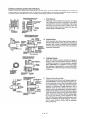
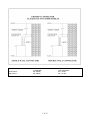
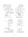
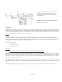
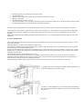
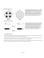
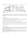
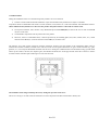
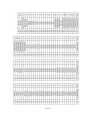
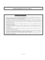
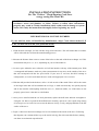
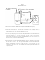
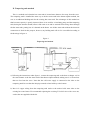
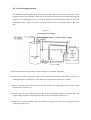
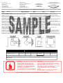
Concern Farmakom M.B. Šabac
Industrijski kombinat“ Guča“ AD Guča industrial complex
Imported by: Sopka Inc
www.sopkainc.com
Solid fuel stove - GULIVER
USER MANUAL
Evaluated to: UL 1482; ULC-S627
Tested to: EN 12815
1 of 23
Dear user,
By purchasing our product you have shown us trust which will not be failed because Guliver stove is the leading product in its
category due to its design and characteristics. Please read these instructions carefully to learn about Guliver stove’s
characteristics and possibilities before first operating it, and keep them for future reference to ensure avoiding irregularities in
your stove’s operation.
Yours sincerely,
GUČA
Warning: NEVER USE OPENING ON THE TOP OF THE FIREBOX FOR FLUE PIPE
CONNETOR. FOR FLUE PIPE CONNECTION, ALWAYS USE OPENING ON OVEN SIDE
AND THE OPPOSITE OF FIREBOX.
2 of 23
Owner’s Manual
for
Guliver
Evaluated to UL 1482, ULCULC-S627 Solid Fuel Room Heater
Tested to: EN 12815
PLEASE READ ALL INSTRUCTIONS BEFORE YOU INSTALL YOUR NEW STOVE.
FAILURE TO FOLLOW INSTRUCTIONS MAY RESULT IN PROPERTY DAMAGE,
BODILY INJURY, OR EVEN DEATH.
SAFETY NOTICE: FOR YOUR SAFETY, CONTACT LOCAL BUILDING OR FIRE
OFFICIAL ABOUT PERMITS, RESTRICTIONS, AND INSTALLATION REQUIREMENTS FOR YOUR AREA. PLEASE CHECK WITH YOUR INSURANCE BEFORE
USING IN YOUR HOME. USE PROFESSIONAL INSTALLER.
CAUTION
Hot while in operation- do not touch
Contact may cause skin burns
Keep children and clothing away
Keep furnishing and other combustible materials a
considerable distance away from stove.
Do not overfire. If stove or chimney connector glows, you are overfiring
DO NOT INSTALL IN MOBILE HOME OR TRAILER
3 of 23
SAFETY INSTRUCTIONS
Read all instructions carefully.
1. The installation of this stove must comply with your local building codes. Please observe the
clearance to combustible. Stove must be 20"(50 cm) from any combustible material, wall, wood,
furniture, paper, etc.
2. Always connect this stove to a chimney and vent outside. This stove requires approved masonry
or factory build 6" diameter UL 103 Type HT chimney, that is high enough to give good draft.
3. Do NOT connect this stove to a chimney flue serving another appliance.
4. Be sure that your chimney is safely constructed and in good repair. Have chimney inspected by
the fire department or a qualified inspector.
5. Creosote or soot may build up in the chimney connector and chimney and may cause a house or
building fire. Inspect the chimney connector and chimney twice monthly during the heating
season and clean if necessary.
6. Burning any kind of fuel uses oxygen from the dwelling. Provide fresh air for proper
combustion from outside the house into the room where the stove is located.
7. To prevent injury, do NOT allow anyone to use this stove who is unfamiliar with the correct
operation of the stove. Do not operate stove while under the influence of drugs or alcohol.
8. Flue connector pipe should be 6" diameter, minimum single wall 24 msg black or 25 msg blued
steel. (Listed to UL 103, Type HT and evaluated to CAN/ULC-S629-M87)
9. Do Not overfire. The special paint used on stove may give off some smoke and an odor while
they are curing during first few fires. Open windows and doors as needed to clear smoke and
odor. Overfiring may cause some damage to the stove.
10. Use only dry, seasoned, natural untreated wood. Do not burn garbage or flammable fluids, such
as gasoline, naphtha, kerosene or engine oil.
11. Use the metal ash drawer only to dispose of ashes. Dispose of ashes in a metal container with a
tight fitting lid. Keep the closed container on a non-combustible floor, well away from all
combustible materials. Keep ashes in the closed container until all cinders have thoroughly
cooled. The ashes may be buried in the ground or picked up by a refuse collec-tor.
12. CAUTION: Hot while in operation. All person, especially young children should be alerted and
trained to stay a safe distance from the stove. Small children should be all the time care-fully
supervised when they are in the same room with the stove.
13. This stove requires non-combustible floor protection.
14. Keep stove area clear and free from all combustible materials such as gasoline and/or other
flammable vapors and liquids at minimum 40".
15. Never leave an unattended woodstove burning on high.
16. It is highly recommended to install smoke and carbon monoxide detectors in the home when
installing a wood stove.
SAVE THESE INSTRUCTIONS
4 of 23
INSTALLATION INSTRUCTION
NOTE: FLOOR EMBER PROTECTION IS REQUIRED FOR SPARK AND ASH
SHIELDING, NOT FOR LIMITING FLOOR TEMPERATURE FROM THE RADIANT
HEAT OF THE APPLIANCE.
1. Proper clearances must be maintained for adequate air circulation. Adequate ventilation must be
provided while operating this stove.
2. The stove must be placed on solid masonry, solid concrete, or when installing on combus-tible floor,
on a UL 1618 listed floor protector or flammable floor must be protected by in-sulating plate ( steel,
brass, marble, stone, ceramic tiles, etc.) . The base must extend at least 18" (46 cm) beyond the front
of the stove and 8"(20 cm) to the sides, and MUST extend under the stove pipe. (Check local
building codes and fire protection ordinances.) Floor pro-tector minimum size; 52" x 51"
3. The stove must have its own flue. DO NOT CONNECT THIS UNIT TO A CHIMNEY SERVING
OTHER APPLIANCES.
4. Connect flue collar to the stove and adapter for creosote leakage. The crimped end of the stove pipe
must be in-stalled facing down to fit inside the adapter. Figure 1, page 11
5. Use three (3) sheet metal screws at each joint of stove pipe and adapter to firmly hold stove pipe
together. Use 6" round black/blue stove pipe (Listed to UL 103, Type HT and evaluat-ed to
CAN/ULC-S629-M87) NOT galvanized pipe. DO NOT CONNECT THIS STOVE TO ANY AIR
DISTRIBUTUIN OR DUCT SYSTEM.
6. Slope any horizontal stove pipe upward toward the chimney at least 1/4 inch for each foot of
horizontal run.
7. You must have at least 18" of clearance between any horizontal pipe and ceiling.
8. The stove pipe must NOT extend to far into the chimney flue.
9. It is recommended that no more than two (2) 90 degree bends be used in the stove pipe installation.
10. Connect to 6" inspected masonry chimney or 6" UL Type HT listed chimney.
A PROFESSIONAL, LICENSED HEATHING AND COOLING CONTRACTOR SHOULD
BE CONSULTED IF YOU HAVE QUESTIONS REGARDING THE INSTALLATION OF
THIS SOLID FUEL BURNING APPLIANCE.
MASONRY CHIMNEY
Before using an existing masonry chimney, clean the chimney, inspect the flue liner and make any
repair needed to be sure it is safe to use.
If connector stove pipe must go through a combustible wall before entering the masonry chim-ney,
consult a qualified mason or chimney dealer. The installation must conform to local fire codes, and
NFPA 211.
Do NOT connect this stove into the same chimney flue as the fireplace or flue from another stove.
If there is a cleanout opening in the base of the chimney, close it tightly.
UL LISTED CHIMNEY
Carefully follow chimney manufacturer's instructions. Us only a UL 103 Type HT Listed Residential Type and Building Heating Appliance Chimney. The top of the chimney must be at least
three (3) feet above the roof and be at least two (2) feet higher than any point of the roof within ten
(10) feet.
5 of 23
Chimney connector systems and clearances
Chimney connector shall not pass through attic or roof space, closet or similar concealed space, or a floor, or
ceiling. When passage through a wall, or partition of combustible is desired, the installation shall con-form to
CAN/CSA-B365, Installation Code for Solid-Fuel-Burning Appliances and Equipment:
6 of 23
CLEARANCES:
Back of Stove
Side of Stove
Combustible
20" (50cm)
20" (50cm)
NON-combustible
6.5" (17cm)
6.5" (17 cm)
7 of 23
8 of 23
MINIMUM CLEARANCES TO COMBUSTIBLE SURFACES
Unit to Sidewall - - - - - - - - - - - -20" (50
Unit to Backwall - - - - - - - - - - - -20" (50
Unit Corner to wall - - - - - - - - - 20" (50
Pipe Connector to Ceiling - - - - - - - 18" (46
cm) CAUTION: KEEP FURNISHING AND OTHER
cm) COMBUSTIBLE MATERIALS AWAY FROM THE
STOVE.
cm)
cm)
Clearances may only be reduced by means approved by regulatory authority.
OPERATION OF THE STOVE
1. Burn wood only. The wood should be natural, air dried (seasoned) for at least six (6)
months. Before lighting open draft, located on front left or right side of stove. Light wood
using paper, twigs, etc. NEVER USE ANY FLAMMABLE LIQUIDS OR GASOLINE TO
START OR FRESHEN UP A FIRE IN THE STOVE.
2. After the fire has been started, adjust the rate of burning by opening or closing the draft control.
3. Do NOT touch the stove after firing until is has cooled.
4. Never overfire this stove by building excessively hot fires.
5. If stove begins to glow or turn red, you are overfiring the stove.
6. Inspect stovepipe every 60 days. Replace immediately if stove pipe is rusting or leaking
smoke.
7. Inspect the stove pipes, connectors, and chimney twice monthly during the heating season
and clean if necessary.
CAUTION: SLOW BURNING FIRES AND EXTENDED USE MAY CAUSE EXCESSIVE CREOSOTE BUILDUP. IGNITION OF CREOSOTE/SOOT OR OVERFIRING
MAY CAUSE CHIMNEY FIRE. CHIMNEY FIRES BURN EXTREMELY HOT AND
MAY IGNITE SURROUNDING MATERIALS. IN CASE OF CHIMNEY FIRE CALL
THE FIRE DEPARTMENT IMMEDIATELY.
CHIMNEY MAINTENANCE - Creosote/Soot Formation and Need for Removal
When wood is burned slowly, it produces tar and other organic vapors which combine with ex-pelled
moisture to form creosote. The creosote vapors condense in relatively cool chimney flue of a slow
burning fire. As a result, creosote residue accumulates on the flue lining. When ignit-ed, this
soot/creosote makes an extremely hot fire.
The chimney and the chimney connector should be inspected at least twice monthly.
If creosote/soot has accumulated, it should be removed. Failure to remove creosote/soot may cause a
house or building fire. Creosote/soot may be removed by using chimney brush. Chimney fires burn
very hot. If the chimney connector glows red, immediately call the fire department.
PROVIDE AIR INTO THE ROOM FOR PROPER COMBUSTION.
9 of 23
CAUTION: HOT WHILE IN OPERATION. KEEP CHILDREN, ANIMALS, CLOTH-ING AND
FURNITURE AWAY FROM THE STOVE. DO NOT TOUCH HOT STOVE. CONTACT MAY
CAUSE SKIN BURNS. TRAIN CHILDREN TO STAY A SAFE DIS-TANCE FROM THE UNIT.
CHILDREN SHOULD BE ALL THE TIME CAREFULLY SUPERVISED WHEN THEY ARE IN
THE SAME ROOM WITH THE STOVE.
CAUTION: NEVER USE CHEMICALS, GASOLINE, KEROSENE, CHARCOAL
LIGHTER FLUID OR SIMILAR FLAMMABLE LIQUIDS TO START OR FRESHEN UP A
FIRE IN THE STOVE.
KEEP ALL FLAMMEBLE LIQUIDS AWAY FROM THE STOVE-WHETER IN USE OR
IN STORAGE.
OPERATING SAFETY PRECAUTIONS
1. NEVER BUILD EXTREMELY LARGE FIRES IN THE STOVE AS DAMAGE TO
THE STOVE OR SMOKE LEAKAGE MAY RESULT.
2. NEVER OVERFIRE THIS STOVE BY BUILDING EXCESSIVELY HOT FIRES AS A
HOUSE OR BULDING FIRE MAY RESULT. YOU ARE OVERFIRING THE STOVE
IF STOVE OR STOVE PIPE BEGINS TO GLOW OR TURN RED.
3. PROVIDE AIR INTO THE ROOM FOR PROPER COMBUSTION.
4. USE SOLID NATURAL AIR DRIED (SEASONED) WOOD and COAL, only.
5. INSPECT STOVE PIPES, CHIMNEY AND STOVE AT LEAST TWICE A MONTH
AND CLEAN IF NECESSARY.
6. WHILE IN OPERATION, KEEP THE FEED DOOR CLOSED ALL THE TIME,
EXCEPT WHILE TENDING THE FIRE. ALWAYS OPEN DRAFT CONTROLER
BEFORE OPENING THE FEED DOOR.
ABOUT DRAFT:
The principle of draft is that warm air rises. Your chimney provides draft which sucks the smoke up
the chimney. The stove does NOT PUSH out the smoke. Your stove has been design and approved for
use under normal conditions. Unacceptable smoking usually indicates poor draft in your chimney.
Normal operating draft for this stove is 12 Pa +- 2 Pa( 0.04 w.c. - 0.055 w.c.). For draft above 15 Pa (
0.06 w.c.) install a stovepipe damper. Gauges to measure draft are readily available at stove stores and
are economical to rent or purchase.
Should you have a problem with inadequate draft, you should contact a licensed heating and
cooling contractor for assistance in solving the problem.
PROBABLE CAUSES FOR SMOKING ARE:
Insufficient chimney height above nearby obstructions.
Clogged or obstructed chimney system
Downdraft caused by nearby trees, hills, buildings, etc.
Negative draft. In a cold chimney, a cold air column rushing down the chimney can prevent stove
start-up causing the stove or chimney pipe joins to smoke. SOLUTION: Open nearby window, and use
small strips of newspaper or tinder loosely placed in the firebox that will pro-vide quick and hot heat
up the chimney, thereby reversing draft.
10 of 23
SINGLE WALL PIPE-MINIMUM CLEARANCES FOR USA/CANADA
Some example of clearance reduction;
• Using heat shields on back and sidewalls allowing at least 1" of space away from the
walls for ventilation. The inch spacing is necessary to ensure air circulation between the
protection and the wall so that the wall is not subject to high temperatures. The spacer
used must be non-combustible. Another method to achieve the same type of protection
is using brick or masonry with 1" air space between the brick or masonry and the wall.
When reducing distances, please check local codes and consult with professional
installer.
• Using special interior double wall stove pipe can reduce distance.
• Protecting wall or ceiling adjacent to the pipe.
• Installing an approve 'pipe heat shield' onto the stove pipe.
• WARNING: Do not place stove to close to the shield. There should be enough space
between for proper air ventilation.
11 of 23
1. INTRODUCTORY NOTES
Please read and observe the instruction carefully. Hereinafter, you shall find the data regarding the stove and recommendations for the
installation and maintenance.
The efficiency depends on the correct installation, which must be carried out by a professional observing the standards and valid
security regulations.
When choosing the place for installation, take care to provide unobstructed airflow and that the floor and the surrounding objects are
made of non-flammable material.
Keep in mind the load-bearing capacity of your floor. Your floor may not be able to take the weight of our product; in that case,
consult a professional to strengthen your floor or install additional load-bearing framing. Moreover, if there is a flammable floor, it
must be protected by an insulating plate (steel, brass, marble, stone, etc.), which extends at least 46 cm(18”) from the front and at
least 20 cm(8”) from the sides.
Do not place armchairs, seats, curtains or any flammable object within 100 cm(40”) in front of the stove as well as within 50 cm(20”)
on the sides.
The cast-metal and sheet-metal parts of the stove are protected by heat-resistant paint; when the stove is operated for the first few
times, this paint stabilizes, producing smoke and odour. When this occurs, ventilate the room where the stove is located. Children
and pregnant women, as well as persons suffering from respiratory problems, should avoid the room where the stove is located for
the first several times the stove is operated.
The stove is designed to be operated with its door closed. The door should be opened only to add fuel. Open door gradually to
equalise internal pressure. Opening the doors suddenly may cause flame and smoke to escape outside. Fuel should be added only
when glowing embers have formed and no intense flames are present.
Avoid operating the stove in adverse weather conditions and strong winds.
Caution: the stove and the door handle will heat up when operated, so it is necessary to take caution measures. Use gloves when
opening the door. Do not touch parts of the stove that are hot (primarily the cast-metal parts, hot plate, and any visible sheet-metal
surfaces).
Keep children away from the stove.
Ensure a constant supply of fresh air into the room where the stove is located, since it uses oxygen from room air for combustion.
Do not allow parts of the stove to become excessively hot, as this will make the stove unsafe and reduce its operating life.
Do not use the stove to burn garbage or use fuels that are inappropriate or not recommended.
Dispose of packaging materials at a proper location. Remove any pieces of cardboard, wood or plastic packaging found in the fire
chamber before operating the stove. Be careful when removing the wooden bracing from inside the fire chamber, as it is fastened by
nails.
Dispose of an unwanted stove properly, respecting local environmental regulations and waste disposal requirements. To ensure
adequate combustion, the draft in the stove chimney flue should be 12±2 Pa. In case of draft greater than 15 Pa, the chimney flue
must be fitted with a damper.
Only spare parts recommended by the manufacturer may be fitted to the stove. The stove may not be modified.
IN CASE OF NON-OBSERVANCE OF THE INDICATIONS ABOVE-QUOTED, THE MANUFACTURER DISCLAIMS
ALL RESPONSIBILITIES FOR POSSIBLE DAMAGE.
2. TECHNICAL DATA
Construction system
Power in kW
Efficiency in %
Pipe diameter in mm
Maximum quantity of fuel - wood in kg
Mean content CO to 13% O2 in %
Weight in kg
Hearth opening size, width x height ( mm )
Hearth size, width x height x depth
Oven size, width x height x depth
Width x height x depth (mm)
*
10,5
87
120
37,000btu
150..(6”)
2,5
5.5lbs
0.1007
390lbs
177
230x270.........(9,06” x 10,63”)
275x325x375......(10,83”x12,79”x14,76”)
360x279x420......(14,17”x10,98”x16,53”)
900x850x665......(35,43”x33,46”x26,18”)
* hearth door is closed automatically (there is the system for automatic door closing with a spring)
* hearth door without the system for automatic door closing
12 of 23
3. RULES FOR INSTALLATION
The stove may not be positioned in the immediate vicinity of the wooden elements, parts made of plastic, textile and other flammable
materials because during the operation (during the fuel combustion) it has high work temperature which is distributed on the outside
of the stove. The smallest distance between the stove and surrounding elements should be 50 cm(20”) (sideways and from the back
side). Safe distance from the front side is 100 cm(40”).
The stove may not be positioned in the immediate vicinity of the cooling equipment (refrigerators, freezers etc.).
In case that the load bearing capacity of the floor does not suit the stove weight, take cautionary measures to increase its load bearing
capacity.
Moreover, if there is a flammable floor, a non flammable plate must be positioned between the floor and the stove and it must extend
at least 46 cm(18”) from the front and at least 20 cm(8”) from the sides.
The stove is connected to the chimney with appropriate smoke pipes in order to provide an adequate tightness and flow of smoke
from the stove to the chimney. The smoke pipe must not be too deeply positioned in the chimney in order not to reduce the surface of
the cross cut and disturb the draft in the chimney.
Guliver provides the possibility of smoke vent hole from the upper or back side of
the stove through appropriate connections which are on the side opposite from the
hearth. The standard parts of the stove are the fitting for the connection with smoke
pipes and the cover for the smoke vent hole (Image 1).
As a standard, there is the cover on the back side, and the fitting for the connection
to the smoke pipes is put in the drawer, and if the user decides to put the smoke vent
hole on the upper side, the fitting should be positioned on the envisaged place. The
cover and the fitting are connected by screws.
If you want the smoke vent hole to be on the backside, unscrew the screws which
connect the cover of the vent hole and the backside of the stove, and fix the smoke
vent hole. The cover should be connected with screws to the stove frame on the
envisaged place. Take care that the screws on the cover and the fitting are in the
channels and are tight enough so that the smoke cannot go through.
The cover on the upper side of the stove which is closer to the hearth should not be
removed (Image 2).
13 of 23
This part shown in the picture is not a towel bar. It
is a heat protector for the cook's stomach. It is
connected by screws in the manner shown in the
picture (Image 3).
This part should not be used for moving the stove,
because it is not its function and its handles made
of grey cast can be broken.
4 CHIMNEY
Special attention should be drawn to the chimney quality which has to be manufactured according to standards. The maintenance of
the chimney has to be regular. The stove is connected to the chimney through the fitting via appropriate smoke pipes, in order to
provide the adequate tightness and the flow of smoke from the stove to the chimney. The smoke pipe must not be positioned too deep
in the chimney in order not to disturb the draft in the chimney.
Airflow
To ensure adequate stove operation, the draft in the stove chimney flue should be 12±2 Pa. The lower value does not allow the proper
combustion, and as the consequence there is the deposit of carbon and excess quantity of smoke which goes out through the grilles or the
door. If the value of the airflow is too high, the combustion shall be too fast, and as the result the heat goes out through the chimney. In case
of draft greater than 15 Pa, the chimney flue must be fitted with a damper.
The signs of bad airflow are:
0·Dirty glass, hot handle
0· Smoke enters the room
Glass Care
Caution: Never operate the stove with a broken door glass. Never build the fire up against the glass.
Warning: Do not use any replacement glass other than the original “ceramic” glass manufactured and supplied for use in this cookstove.
Replacement glass is available from manufacturer or authorized dealer. Do not abuse glass door by striking or slamming it. Never clean hot
glass. Never use abrasive cleaner. When necessary, the glass can be cleaned with low alkaline content commercial stove glass cleaners,
which are available from your local dealer.
Glass Replacement Procedure: Insure appliance is not in operation and is thoroughly cooled. Remove screws and glass clips.Lift glass
from glass clips. Replace seal material. Trim to length and butt together. Replace glass into door, being sure not to over tighten screws and
clips.
Oven glass: Replace oven glass only with original “fully tempered soda-lime” glass available from manufacturer or authorized dealer.
14 of 23
4.1 General characteristics
Add chimney sections, according to the manufacturer’s installation instructions. The chimney must extend at least, 3
feet above its point of contact with the roof and at least 2 feet higher than any wall, roof, building or
obstacle within 10 feet horizontally.
The chimney guarantees the conveyance of the fumes outwards even when there are strong horizontal winds and stops them from
being blown back down the chimney.
Bad maintenance of the chimney stops the smoke passage due to breakage or separation of cement mortar, brick or other material
used for chimney construction, as well as due to product deposits combustion and intrusion of foreign objects.
Chimney must have sufficient heat insulation; otherwise it can lead to condensation.
The internal parts of the whole flue should have a smooth surface, and the material used should be chemically and thermally
resistant to products of combustion.
In case of any problems connected with chimney, you should consult professionals and chimney sweepers.
LIGHTING
Prior to the first stove lighting, it is necessary to wipe all stove surfaces with a dry cloth, remove dust, oil and impurities from the
stove plate and the oven in order to avoid their combustion and uccurence of unpleasant odours and smoke.
The first time that the appliance is lit, there will be an unpleasant odour and smoke given off, especially from the stove plate surface,
as well as from the other parts protected with a heat resistant paint. This is a normal occurrence because the paint stabilizes on
temperatures above 250°C du ring the first lighting. A good ventilation of the room where the stove is located must be ensured.
The ignition is performed in the following manner:
• The handle of the regulator of the gases flow should be pulled towards you, thus enabling the smoke flow towards the chimney via
the shortest route.
15 of 23
•
•
•
•
•
•
Position the primary air regulator into the open position,
open the hearth door,
put the necessary fuel into the hearth (ungreased paper, small pieces of wood),
Ignition is performed,
The hearth and ashtray door is closed,
After the initial flame, wider wood logs should be put into the hearth, the hearth door is closed, the draft is reduced to half,
and the regulator handle is positioned into the front position (Image 5).
Fuels like petrol or light distillate oil and similar fuels must not be used, because they can lead to stove damaging and explosion.
Among the others, the following cannot be burnt: organic waste, food leftovers, used and painted wood, plastic objects, flammable
and explosive materials the combustion of which disturbs proper operation of the stove and can cause damage and environment
pollution.
High outside temperatures may cause bad airflow (draft) in the chimney, so it is recommended to put smaller quantities of fuel more
frequently.
6. STOVE OPERATION
We recommend to split the quantity of fuel into half and to gradually heat the stove when used for the first time, in order to control
and test the operation.
Maximum quantity of wood for safe operation is 2,5kg (5.5lbs).
The hearth door should be opened only when necessary, in order to add new quantity of wood. The next quantity of wood is added
only after the previous quantity has been burned.
Do not allow the obstruction caused by ashes and unburned fuel. Clean the obstruction. The door should be opened slowly, without
abrupt moves, in order to allow the pressures in the hearth and the room to become equal. In that way you prevent the exit of smoke
and flame from the hearth.
The hearth door must be closed when the stove is used.
The wood should have maximum 20% humidity. In addition to bad combustion effect, wet wood leaves deposits on the glass.
The ashtray should be regularly cleaned so there is always space for ashes and the ash must not be allowed to reach the grid level,
otherwise the air cannot flow into the combustion chamber.
The handle of the regulator of gases flow used for the selection of the regime of the stove operation has two positions.
1. for lighting the fire and cooking, the handle should be pulled out, as
well as when adding a new quantity of fuel.
2. When it is used simultaneously for cooking, baking and heating or
just for heating, the handle of regulator of gases flow is pushed inside
(see picture).
16 of 23
Regulation of primary air
The primary air control should be put in the opened
positionduring lighting and kept that way till the moment
of the establishment of the stabile operation of the stove
after putting larger pieces of wood. After that the
regulator should be put in the closed position and held in
that position during the stove operation. When the
regulator is closed it prevents the air flow under the grid
by which it lessens the combustion intensity. If you want
fast fuel combustion, open the primary air control.
Regulation of secondary air
The secondary air regulator should be put in the position
closed during ignition and held in that position until
you establish the operation heating regime. After that,
put the regulator into the position opened and hold it in
that position during the stove is in operation. The
secondary air is used to clean the glass on the hearth
door and for better combustion. During the stove
operation, the movable part of the regulator is heated, so
use the additional equipment during regulation.
7. CLEANING THE STOVE
We recommend removing the ash produced every day. Never allow the ash accumulate to the point where it touches the grate;
this would obstruct the circulation of primary air and slowly suffocate the fire.
When cleaning the outside surfaces of the stove, avoid abrasive products which would damage the protective paint. Do not use
chemicals that contain diluents, because the cast parts are protected by heat resistant paint.
Panoramic door glass should be cleaned with normal detergent and exclusively after getting cold. Do not use abrasive products
because you will damage the glass surface. After cleaning, rinse with pure water and dry.
17 of 23
The additional equipment that is delivered with the stove is the glove and equipment for shaking of embers and removal of ashtray
(see picture).
Cleaning of channels for flow of gas products of combustion under the stove should be performed in the following
manner: Remove the decorative panel (below the oven door) by tightening the screws (picture10). By stump, remove layers of soot
from the bottom of the stove and under the bottom of the oven. After cleaning, return the decorative plate in the initial position and
attach it with screws.
8. CONSUMABLES
The following are considered consumables and therefore not covered by the warranty:
all gaskets, glass parts, the paints, the ceramics and the parts with chemical coating (chrome, nickel, zinc parts). The warranty does
not cover damages caused by improper installation, incorrect connection not in compliance with the instructions which accompany
the product, or by tempering by unqualified or unauthorized personnel.
9. WHAT TO DO IF YOU DO NOT INTEND TO USE THE STOVE FOR AN EXTENDED PERIOD
First, clean the hearth, the smoke pipes and the flue, trying to eliminate completely the ash and other residuals. In case you disconnect
the appliance from the chimney, close its opening in order to allow operation of other possible appliances connected to the same flue.
The cleaning of the flue should be done at least once a year; in the meanwhile check the state of the gaskets and replace them if
necessary. In presence of dampness in the room where the stove has been placed, we advise you to put absorbent salts into the hearth
and other stove openings.
10. STOVE DESCRIPTION
The stove is intended for heating (through cast and brass parts and glass) and preparation of food (on the plate and in the oven). If fast
cooking is required add smaller quantities of fuel, open the air vent holes, pull out the handle of regulator of smoke gases. For
simultaneous cooking, baking and heating, the handle of regulator of smoke gases is pushed inside and the intensity of combustion is
regulated through the primary air control.
The stove Guliver has the possibility of air flow regulation for combustion, thus selecting the regime of the stove operation, thus
achieving the better efficiency and better level of wood usage.
The plate frame, all doors, hearth coatings, junction for smoke outlet and gallery holders are made of grey cast. The glass on the stove
and hearth door is resistant to high temperatures and adequate for the intended use. There is a thermometer on the stove glass.
Tightenings are made without the use of asbestos. Cast and brass parts are protected with heat resistant colour, and there is a chrome
coating on some positions (handles, gallery).
18 of 23
11. FIRE SAFETY
During the installation of the stove the following safety measures are to be followed:
1) In order to ensure sufficient thermal insulation, respect the minimum safety distance from objects or furniture
components which are flammable and sensitive to heat (furniture, wood, fabrics etc.) and from materials with flammable structure.
All the minimum safety distances are shown on the product data plate and lower values MUST NOT be used.
2) Do not place armchairs, seats, curtains or any flammable object within 100cm(40”) in front of the stove as well as within 50
cm(20”) on the sides.
3) No flammable components must be present above the product.
4) Moreover, if there is a flammable floor, it must be protected by an insulating plate (steel, brass, marble, stone, etc.), which
extends at least 46cm(18”) from the front and at least 20cm(8”) from the sides.
The chimney stove must operate exclusively with the ash drawer inserted. The solid residue of the combustion (ashes) must be
collected in a hermetic container, resistant to fire. The stove must never be ignited when there are gas or steam emissions (e.g. glue,
gasoline, etc.). Never deposit flammable materials near the stove. During the combustion there will be thermal energy spread which
warms up the surfaces, the door, the fireplace glass, the handles and knobs, the smoke pipe and the front side of the stove. Please
avoid the contact with these parts without gloves or the relevant tools.
Warn children of the danger and keep them away during the operation of the stove.
The use of a wrong or wet fuel causes the formation of creosote deposits in the flue and will fuel a chimney fire.
19 of 23
12. WHAT TO DO IF YOUR STOVE DOES NOT OPERATE AS INDICATED
12.1 Difficulties during operation
• Check whether the chimney entrance is made adequately.
• Check whether the chimney dimensions are correct and suitable for the device.
• Check the thermic insulation of the chimney and if it is made according to standard.
• The hearth door must be closed properly,
• Check if the draft is in the allowed limitations.
12.2 Ignition difficulties
• Open the primary air and smoke control.
• Use dry wood.
• Ventilate the room to obtain sufficient quantity of oxygen.
• The chimney must be adapted to the device for which it is used.
12.3 Smoke coming out
• Check if the primary air control is opened.
• Check whether there is leaking on the chimney entrance.
• Check if there are any obstacles from ashes and other remains.
• Check the airflow.
• Check the draft in the chimney.
• Check the screws.
12.4 Glass getting dirty
• Wet wood: use dry wood (with max 20 % moisture)
• Wrong fuel (see allowed materials)
• Too much fuel in the hearth or the wood touches the glass
• Insufficient air flow (see connecting the chimney)
• Wrong regulation: if the secondary regulator is closed, the glass gets dirty after short time.
12.5 Condensation
• During first few ignitions, condensation is normal.
• If the problem lasts, check the wood you use; it must not be wet or poorly dried.
• The chimney must not have any defects or cool the gas flow too quickly.
Important: The stove has been made from materials which are NOT harmful for health.
13. GENERAL NOTES
If all recommendations for installation, regulation of operation and cleaning have been respected, the stove represents a safe domestic
appliance.
In case of any problems, please contact the producer or distributor by telephone or in written form. Contact data are given at the end
of this instruction.
Any defect on the stove shall be removed by the authorized service.
If an unauthorized person performs service or any changes on the stove, the owner of the stove loses the right for the service provided
by the manufacturer’s warranty.
The supply of spare parts is performed exclusively through the factory service, based on the positions and pictures in this instruction
and their names.
The manufacturer is not liable if the buyer does not respect the installation and operation manual.
The manufacturer reserves the right to make modifications in appearance, dimensions and the model without the previous notice.
20 of 23
14. COMPONENT PARTS
21 of 23
22 of 23
"Guca IK" products are manufactured under the strict Standard of the World Recognize
ISO 9001: 2000 Quality Assurance Certificate.
Limited One year Warranty
"Guca IK" warrants its products against manufacturing defects to the original purchaser only—i.e.,
individual (register customer) wh ose name appear on the warranty registration card., for a period of One
year from date of purchase from only an authorized dealer.
If within the one year period, your product should develop a defect due to materials or workmanship of
the original new product, Guca IK (manufacturer), Sopka Inc (importer), or your authorized dealer will
supply ONLY the parts necessary to make the repairs. (Labor Not Included) and is subject to following
condition and limitations:
This limited warranty does not cover damages caused by misuse, lack of maintenance, accident,
alterations, abuse or neglect.
This limited warranty does not cover any scratches, dents, corrosion or discoloring caused by excessive
heat, cleaning chemicals, nor chipping on porcelain enamel parts, nor any venting components used in
the installation.
Installation must be done in accordance with installation instructions included with product and all local
and national building and fire codes.
Guca IK will not be liable for incidental and consequential damage of any nature. This warranty gives
the purchaser specific legal rights which may vary from state to state. No other warranty is to be implied
or expressed, including warranties implied for a specific or particular purpose.
Guca IK reserves the right to have its representative inspect any product or part thereof prior to
honoring any warranty claim.
23 of 23
INSTALLATION INSTRUCTIONS
For The "Guliver" Wood Burning Cook Stove
energy saving Hot Water Kit
CAUTION: These installation instructions are meant to be used as a guide for
woodstove owner and plumber to follow. Failure to follow these instructions
properly may result in a faulty installation. which could result in damage to system
and/or self. Study the instructions thoroughly before beginning any work.
USE PROFESSIONAL-LICENSE PLUMBER.
If your unit has water coil installed by manufacturer, skip 1-7 and choose method I, II
or III, one that will best suit your particular needs.
1. Wash the heat exchanger coil out with hot soapy water and rinse. This will insure that no residues
will be left inside the coil from the manufacturing process.
2. Measure the distance from center to center of the holes on the ends of the heat exchanger coil. This
measurement may be 6", 8", or 9“, depending on your coil kit model no.
3. Locate a space within the stove where the coil will not interfere with any of the internal parts. With
a centerpunch and hammer, mark two points (measurement in step one) on the outside of the stove
that will correspond with the free space inside. If your stove is cast iron, DO NOT attempt to
centerpunch it, as it will crack. Mark the stove with a felt tipped pen if it is cast iron.
4. With the drill provided in the holesaw, dril a 1/4" hole at each of the marks. These will be the center
of the larger holes that will accomodate the coil legs, so make sure that they are spaced properly
and do not interfere with anything inside the stove, ie., firebrick, baffles, etc. If the holes are not
properly spaced, now is the time to re-drill them.
5. Once you are satisfied with the 1/4" hole placement, replace the drill in the holesaw and tighten it.
Using the 1/4" hole as a guide for the drill/holesaw assembly, operate at a slow speed using cutting
oil to keep it cool as it cuts. Be sure to run the holesaw slowly, evenly, and perpendicular to the flat
surface of the stove.
6. Figure 1 shows how the heat exchanger coil is to be fastened to the inside of the stove. Following
this diagram, run a locknut all the way to the end of each leg, flat side toward the firebox, making
sure there are no threads exposed inside.
Installation of water coil inside the firebox
7. Place the coil through the holes from the inside of the firebox and run a washer and nut down each
leg on the outside of the stove. Before tightening the nuts down completely, wrap a piece of hitemp fiberglass rope gasket, provided with the kit, around each threaded leg between the washer
and the outside of the firebox. Tighten the locknuts down securely to insure an air-tight installation.
The heat exchanger coil may be installed vertically, as shown in figure 2, or horizontally, in which
case it does not matter which leg is plumbed to or from the hot water heater as they will both be at
the same level.
The installation is now ready to be plumbed to your existing domestic hot water system. Choose one
of the three methods described below that will best suit your particular needs:
I. Thermo-siphon method
This is the simplest and most economical method, however, the hot water tank must be less than ten
feet from the stove. The water inlet, where the temp./press. relief valve is located, must be higher than
the top leg of the coil. The hot uater tank should be elevated, if neccessary, to allow for proper thernosiphon action (the method by which hot water will circulate automatically through the system).
Figure 2.
Thermo-siphon method
a) Shut off the hot water heater and the cold water supply to it. Drain the tank completely.
b) Remove the existing temp./press. relief valve and discard. Install a short 3/4" nipple and tee (1)
along with the new temp./press. relief valve supplied with the kit.
c) Run 3/4" copper tubing along with the neccessary fittings between the hot water tank and the top leg
of the water coil. Install a 3/4" vent elbow and automatic "float type" air vent (2) in the high point
of the line. Run 3/4" tubing from the release exit of the temp./press. relief valve downward (3) so
that hot water may escape in the event of overheating.
d) Remove the drain valve at the bottom of the tank. Install a short 3/4" nipple and tee and re-install
the drain valve to the tee (4). Run 3/4" copper tubing with the neccessary fittings between the
drain/tee combination and the lower leg of the coil. After all of the connections have been
completed, you may refill the tank. Turn on the hot water heater only after the tank has been
completely refilled.
II. Tempering tank method
This is a method used when the hot water tank is located more than ten feet away from the stove.
The tempering tank is installed the same way as the hot water tank in the thermo-siphon method, but
acts as an additional holding tank for the existing hot water tank. The advantages of this method are
that hot water capacity is greatly increased, there is no need for a circulating pump, and the tempering
tank, during the summer months, allows cold water to set and be warmed before being drawn through
the hot water tank, putting less of a demand on the heater. An old hot water tank without the electrical
connections is ideal for this purpose, however, any holding tank will do if it is modified according to
the drawings in figure 4.
Figure 3.
Tempering tank method
a) Following the instructions under figure 3, connect the tempering tank to the heat exchanger coil in
the same manner as the hot water tank in the thermo-siphon method, making sure it is located less
than ten feet from the stove. Note that the cold water supply is connected to the inlet on the
tempering tank. Be sure that the inlet pipe extends at least halfway to the bottom.
b) Run 3/4" copper tubing from the tempering tank outlet to the marked cold water inlet on the
existing hot water heater. We recommend replacing the exsisting T/P relief valve with a new one,
such as the one supplied with the kit.
III. Circulating pump method
This method is used when the hot water heater tank is more then ten feet away from the stove and a
tempering tank is not avalllable, or the stove is on a higher level than the hot water heater tank. In
addition to a circulating pump, you will need an aquastat to thermostatically control it as the water
temperature varies. A gate valve place near the pump will allow for manual control of the water
flow.
Figure 4.
Circulating pump method
a) Shut off hot water heater and the cold water supply to it and drain completely.
b) Remove the exsisting temp/press. relief valve on the hot water heater and replace it with a 3/4"
short nipple and tee. Install a new valve and run an escape line downward (1) as shown.
c) Remove the drain valve at the bottom of the tank. Install a 3/4" short nipple and tee and re-install
the drain valve to the tee (2).
d) Install a gate valve (3) leading away from the tee and a circulating pump (4) as shown. Run 3/4"
copper tubing from the circulating pump to the lower leg of the heat exchanger coil.
e) Install a 3/4" tee to the top leg of the coil with the new temp/press. relief valve, supplied in the kit,
coming out of the tee (5).
f) Run 3/4" copper tubing from the tee at thu top leg of the coil and install an aquastat, (6) wiring it to
the circulating pump. Complete the 3/4“ copper line by running it back to the tee at the top of the
hot water tank, making sure to install a 3/4" vent elbow and automatic air vent (7) at the high point
of the line. The system is now ready to be refilled and the hot water heater turned back on.
ALWAYS be sure the sensing element of the temp/press relief valve is immersed in water in the upper
6" of the heater tank.
NEVER use plastic tubing between the coil installation and the hot water heater. The heat from the
stove or furnace could melt the plastic.
NEVER connect a supply line to the escape outlet of any temp,/press, relief valve.
Hot water generated from the heat exchanger installation could reach temperatures of 180-190 degrees
F. if it is not used. It is advisable to install a hot water tempering valve, adjusted to 130 degrees F., to
avoid scalding temperatures.
IK “Guča“ AD
Albanske spomenice bb
Guča, Serbia
+381 32 854 301
www.ikguca.com
[email protected]
Made in Serbia
Imported and Distributed by:
Sopka Inc., USA
216-543-7002
www.sopkainc.com
[email protected]
Listed and Labeled by:
Guardian Fire Testing Laboratory
Evaluated to:
UL 1482, ULC-S627
Tested to:
EN 12815: 2001
www.firetesting.com
- Solid Fuel Room Heater - For Use with Solid Wood Fuel only
Model
Modèle
Guliver
Date of manufacture
Date of fabrication
TO PREVENT HOUSE FIRES:
Contact local building or fire officials about restrictions and installation
inspection in your area.
Install and use only in accordance with manufacturers's installaton and
operating instructions and local codes.
In the absence of any local codes, installation must meet minimum
requirements of NFPA 211 in the USA, and B365 in Canada.
Refer to manufacturer’s instructions and local codes for precautions
required for passing a chimney through a combustible wall or ceiling.
Inspect and clean chimney system frequently in accordance with
manufacturer’s instruction.
Do not connect this stove to a chimney flue serving another appliance.
Do not use grate or elevate fire. Build wood fire directly on hearth.
Flue connector pipe must be 6” diameter, minimum single wall 24 msg
black or 25 msg blued steel.
Chimney must be factory built 6” diameter Class,"A" 103 Type HT, or masonry.
TO PREVENT CREOSOTE FIRES:
Inspect and clean chimney frequently - under certain conditions of use, creosote
buildup may occur rapidly. Do not use other fuels than firewood.
CAUTION: Fully open combustion air control before opening the fuel
feed door. Only operate the wood heater with the doors closed.
Replace fire box glass only with original "Ceramic" glass available from
manufacturer or authorized dealer, only.
Parallel & Corner
Month
Mois
Year
Année
Serial No.
No de série
POUR EVITER LES INCENDIES DOMESTIQUES:
Contactez les Autorités des bâtiments et les pompiers pour obtenir des instructions
concernant les restrictions et inspections d'installation dans votre région. Installez et
utillisez cet appareil uniquement en respectant les instructions d'installation et d'utilisation
du fabriquant. Respectez également les réglementations locales.
En l' absence de réglementations locales, l' installation doit respecter les normes minimales
de NFPA 211 aux Etats -Unis et B365 au Canada.
Référez-vous aux instructions du fabriquant aux réglementations locales pour obtenir des
instructions concernant les précautions nécessaires pour le passage de la cheminée á
travers une paroi ou un plafond combustible. Inspectez et nettoyez le systeme de cheminée
fréquement selon les instructions du fabriquant.
Ne connectez pas ce poele a un conduit de cheminée utilisé par un autre appareil. N'utilisez
pas de grille et ne faites pas monter le feu. Etablissez le feu de bois directement dans l'âtre.
Le tuyau de connexion au conduit doit avoir un diametre de 6" (152 mm), une paroi unique
en acier de 24 msg (noir) ou 25 msg (bleu).
Le matériau de la cheminée doit etre 103HT de classe A de 6" (152 mm) ou une
construction en dur.
POUR EVITER LES FEUX DE CREOSOTE:
Inspectez et nettoyez la cheminée régulierement - Sous certaines condition d'emploi, la
créosote peut s'accumuler rapidement. Ne pas utiliser d'autres combustibles que le bois.
ATTENTION: Ouvrez complétement le contrôle d' air de combustion avant d' ouvrir la
porte du foyer. N'utilisez le poele que lorsque les portes sont fermées. Remplacez la vitre
du foyer de feu seulement par une vitre en "céramique" d'origine, fournieuniquement, par
le fabricant ou un revendeur autorisé.
A
B
C
D
E
F
Single Wall Connector
20" (50cm)
18" (46cm)
20" (50cm)
18" (46cm)
18" (46 cm)
84" (213 cm)
Double Wall Connector
20" (50cm)
18" (46cm)
20" (50cm)
18" (46cm)
18" (46 cm)
84" (213 cm)
Floor / Ember protector minimum size 52" x 51" ( 132cm x 129.5cm)
Clearances can be reduced with shielding acceptable to local authorities. Reduced installation must comply with NFPA 211 or
CAN/CSA-B365.
CAUTION
HOT WHILE IN OPERATION - DO NOT TOUCH.
KEEP CHILDREN AND CLOTHING AWAY.
CONTACT MAY CAUSE SKIN BURNS. SEE
NAMEPLATE AND INSTRUCTIONS. KEEP
FURNISHINGS AND OTHER COMBUSTIBLE
MATERIALS A CONSIDERABLE DISTANCE
AWAY FROM THE APPLIANCE.
DO NOT OVERFIRE - IF HEATER OR CHIMNEY
CONNECTOR GLOWS, YOU ARE OVERFIRING.
ATTENTION
CHAUD PENDANT LE FONCTIONNEMENT
- NE PAS TOUCHER. TENIR ELOIGNES LES ENFANTS
ET LES VETEMENTS - LE CONTACT PEU CAUSER DES
BRULURES. CONSULTEZ LA PLAQUE
D'IMMATRICULATION ET LES INSTRUCTIONS. TENIR
LES FOURNITURES ET AUTRES MATIERES
COMBUSTIBLES A DISTANCE DE L'APPAREIL.
EVITER
DE SURCHAUFFER - SI LE FEU OU LA CHEMINE
DEVIENT ROUGE, VOUS SURCHAUFFEZ.
DO NOT REMOVE THIS LABEL / NE PAS ENLEVER CETTE ETIQUETTE