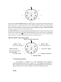
1
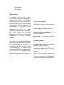
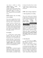
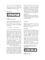
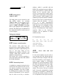
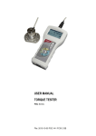
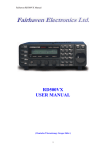
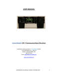
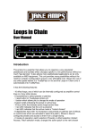
RD500 Radio Database
User manual
Table of contents
1. Introduction
2. Connecting the RD500
a.
b.
c.
d.
Power supply
Aerial
cassette
PC
3. Getting started
4. Using the receivers controls
4.1 Auxiliary menu.
Key 1. ATT (HF/VHF Attenuator).
Key 2. AMP (Aerial amplifier).
Key 3. CAS (cassette control).
Key 4. LPF (treble cut low pass filter).
Key 5. AVC (automatic volume control).
Key 6. More (Record counter and memory partition).
4.2
4.3
4.4
4.5
4.6
4.7
4.8
BP (C.W.) filter.
Variable (Notch and peak) filter.
AGC setup.
Noise blanker.
Pass band shifting.
VFO selection.
Step size selection.
Version 1.10
4.9 Time clock.
b. Display mode.
a. Setting the clock.
c. Setting the timers.
d. Time zones.
4.10 Connection to a computer and the p.c. software.
4.11 Key lock.
4.12 Scan setup menu.
a. Stop.
b. Continuous.
c. Hold.
d. Pause.
e. Auto memory.
f. Auto tune.
4.13 Frequency entry, fast tuning, fast stepping.
4.14 Audio recording and playback.
a. Reserving memory.
b. Record menu.
c. Editing.
d. Repeat.
4.15
4.16
4.17
4.18
4.19
4.20
Mode.
Decode and audio interface.
Bands. (Scanning between frequency limits)
Skip frequencies.
Priority channel.
The database system.
a. Memory records and group names.
b. Deleting records.
c. Searching records using text.
d. Moving groups
4.21
4.22
4.23
4.24
4.25
S.Meter.
Tuning meter.
Remote control handset.
External keyboard.
Error codes and error messages.
5
6
7
8
ITU country codes.
Connection details.
Receiver system description
CW filter shapes.
9 Specifications.
10 Performance.
11 Guarantee
1. Introduction
The RD500 is a new kind of radio
receiver which offers some exciting new
features that may well become
commonplace in the future. With the trend
towards increasing chip complexity, falling
memory prices, and increasing ease of
dissemination of information, many
conventional radio memory systems will
undoubtedly be replaced by small
database systems that allow the user to
find station names and associated
information with ease, and without the
inconvenience of complete computer
systems.
This manual attempts to show the user
how easy it can be to use the RD500 and
make the most of this exiting new radio.
We recommend that you read section 3
“Getting started” which will give a very
brief introduction to the RD500’s main
features, for users who are already familiar
with receivers. The handbook then
describes the receiver’s functions in detail
taking each button in turn. For reasons of
safety you should also read the following
chapter.
Accessories supplied
The RD500 is shipped with the following
accessories:Power supply, normally rated at 230V.
Remote control with batteries. – For
text entry and control.
RS232 lead. – For database upload and
download to the receiver.
Operating manual.
Compact Disk, containing the Fairhaven
Database with demonstration
file. The File Converter - for importing and
manipulating frequency lists, our web site,
and Hamcomm, JVfax and SSTV
software.
There are also help files associated with
most of the software which can be printed
by the user if required. The File converter
has an extensive help and tutorial section.
Rear panel connections
2.
Connecting the RD500
a. Power supply.
The RD500 is designed to operate from a
12V-14V power supply or vehicle
battery. The power supply lead should be
inserted into the rear connector labelled
13.8V the centre connector is positive
with respect to ground. A vehicle power
lead should be fused at 1 amp (slow
blow), if a larger fuse type is used fault
conditions may damage the receiver’s
circuit board fusable link. The mains
power supply is designed to be plugged
into a 230V 13A mains socket. Power
consumption is approx. 8W. The
maximum current available via the PC
keyboard or cassette socket is 100mA,
this should not be exceeded.
most of the VHF and UHF spectrum, but
for best results a specific aerial should be
used for each band, especially at higher
frequencies. Aerials should be suspended
outside of buildings, as high as possible
(unless a specific aerial to ground distance
is specified), and away from power lines.
To minimise the slight amount of
interference produced by the receiver’s
processor and display it is recommended
to use a few metres of screened cable
between the receiver and the aerial.
Take care when erecting aerials in the
vicinity of overhe ad power lines.
c. Cassette – see appendix 6
d. PC connection – see appendix 6
(Appendix 6 gives detailed information on
the din socket connections)
b. Aerial connection.
For long, medium and shortwave use,
almost any length of wire or whip aerial
can be used with the RD500. Short aerials
(less than 5 metres) can be connected to
the whip antenna input and an aerial tuner
unit may be useful to get the most out of a
random length of wire. At VHF and UHF
discone type aerials can offer good results,
even 2 meter band whips can work well
across
3.
Getting started. – Read This!
Connect an HF aerial into the main aerial
socket or a VHF/UHF aerial into the
upper N-Type sockets. Connect the
power supply to the receiver and plug it
into a suitable mains supply. (See chapter
2 for more information on power supplies
and aerials).
Switch on the receiver by rotating the
squelch control clockwise until it clicks.
The receiver will perform a self check and
set itself to the last used frequency,
memory or band.
The receiver can be tuned with the
tuning wheel and you may like to try
entering frequencies via its keypad,
followed by enter. To change mode Press
the <MODE> key (top left) followed by
one or more numerical key presses on the
main keypad area. The S-meter can be
switched on and off with the <SHIFT>
button (at bottom of keypad) then
<S.METER> (top right), the angled
brackets used in this manual refer to
buttons on the radio.
Check out the recorder by
pressing <SHIFT> then <ENTER>. Press
1 to record then 2 to play back
<CANCEL> returns to the main screens.
The receiver is factory shipped
with a database of stations which all have
a name of up to 20 characters. It is
possible to find any of these stations by
using the text searching facility. So to find
a name such as “Moscow” or a type of
station like Volmet, first chose a group
which contains entries by pressing
<GROUP> and pressing the up and down
keys, top right), then press <MEM> to
put the receiver into memory mode, finally
press <SHIFT><FIND> and enter a
word using the handset, press <ENTER>
followed by 2 for “search all groups”.
The receiver will search for a while then
set itself to the first match, use the up and
down keys to see the other matches.
Scanning
To scan from the current frequency, turn
the squelch control clockwise until the
receiver is silenced, then press <SCAN>
and the receiver will scan up in frequency,
the down button can be pressed to scan
down. The step size can be altered by
pressing <SHIFT><STEP> and using the
<UP> and <DOWN> buttons, return the
step size to “Normal” after use.
To scan between two frequency limits,
use the <BAND> key (see section 4.17).
To scan memories chose a group by
pressing <GROUP> and use the up and
down keys followed by <MEM> to select
the chosen group of memories, adjust the
squelch level, then press <SCAN>. The
receiver will stop when the first active
channel is encountered but different scan
modes can be selected by pressing
<SHIFT><SCAN> see section 4.12
You may now like to try out some of the
other facilities, these are accessed by
pressing <SHIFT> followed by any other
button. Use <CANCEL> to return to the
basic operating mode. Do not attempt reallocate memory space at this stage,
<SHIFT> 1,6,1, will erase all database
entries.
4.
Using the receiver’s controls.
The design of the receiver allows easy
access to most functions without having to
use a lot of menus. There now follows a
more detailed description of all the
facilities, starting with key 1.
4.1
Auxiliary menu
<SHIFT><1>
Pressing SHIFT-1 reveals the auxiliary
settings menu, individual functions can be
selected by pressing the corresponding
number, active functions are indicated with
square brackets. The auxiliary settings
can be individually specified for each
memory, band or VFO, except for
AMP and ATT settings which are set
universally.
1 [ATT] 2 AMP 3 CAS
4 LPF 5 [AVC] 6 MORE
ATT (Attenuator)
Aux Key 1.
Inserts a 20dB attenuator into the main
HF aerial path to reduce the receiver’s
sensitivity when the receiver is likely to be
overloaded by strong signals.
AMP (HF Aerial amplifier).
Aux Key 2.
This control connects the HF aerial
amplifier, and its associated selector
switch, (on the back panel) into the aerial
path. The high impedance (HI-Z) whip
aerial input is designed to give extra
sensitivity for short HF aerials, although it
does not have the large signal handling
ability of the main antenna input. The AMP
facility also provides gain to the MAIN
aerial input when selected on the rear
panel, but should be used with caution as it
can degrade the wanted signal due to
overloading
signals.
from
other,
off-channel
CAS (cassette control)
Aux Key 3.
This key switches on the cassette recorder
which can be connected to the Din socket
marked CASSETTE. The cassette is
activated when CAS is selected and the
squelch is raised. The socket can be
configured to provide a 12 volt output that
is switched by the squelch. See appendix
for connection details.
LPF (treble cut low pass filter)
Aux Key 4.
LPF is a steep, low pass filter circuit
which can improve signals that are subject
to a high degree of noise.
AVC (automatic volume control)
Aux Key 5.
This facility acts as an audio compressor,
which can reduce audio level variations
when listening to signals that are subject
to fading. It works by augmenting the
AGC system (which is carrier derived),
by feeding back the audio signal level to
the AGC system.
MORE
Aux Key 6.
Provides access to the next part of the
menu.
Option 1. Reserve memory
This allows the receiver’s memory to be
partitioned to provide space for audio
recording, see section 4.14
ALTERING
THE
MEMORY
PARTITION WILL ERASE ALL
MEMORIES.
Option 2. Free record count
The free record counter shows the
remaining number of empty records that
are available for use.
We now return to the main shift key
facilities on the receiver, press cancel.
4.2
BP (stereo CW) filter
<SHIFT>Key 2
These filter options are active when CW is
selected from the mode menu. If BP
(bandpass) is selected the filters spread
the audio spectrum into a stereo
panorama, which gives spatial separation
to C.W. signals. This makes it easier to
focus upon individual signals, those that
are lower than the filter frequency appear
to the left, and frequencies that are higher
than the filter roll off appear to the right.
The filter can be peaked at 850Hz in 3
selectable bandwidths (Keys 4,5 and 6).
A low pass filter option (LP) is also
provided this gives mono audio which is
rolled off at 850Hz, peaking the filter by
selecting narrower bandwidths, gives a
conventional band pass filter shape. See
appendix for filter shape table (section 8).
CW filter display
CW F i l t 1 [LP] 2 BP
4[F l a t] 5 M i d 6 P k
4.3
Variable Notch and peak filter.
<SHIFT>Key 3.
This filter is provided to eliminate tones
caused by adjacent signals (in notch
mode), or it can be used to select C.W.
signals in peak mode. The filter frequency
is controlled by the knob marked 'filter'.
In order to eliminate an interfering tone, it
is usual to start with the filter set to
“peak” so that the frequency of the filter
can be set to the pitch of the tone. Once
this has been done select notch and tune
the filter or the tuning wheel carefully until
the interfering tone disappears.
VARIABLE FILTER . . .
1 [OFF] 2 NTCH 3 PK
4.4
AGC (Automatic gain control)
<SHIFT><Key 4>
The receiver’s A.G.C. response is
tailored to give a good response to ssb
signals i.e. a fast attack and a short hold
period followed by a fast decay. The
timing of the response is user presettable
for each mode. Select the mode (Keys 4
to 6), then select the required speed
(keys 1 to 3) the setup will be
permanently stored when the menu is
left. A slow response is recommended
for SYNC modes, a fast response is
useful in AM modes, when tuning or
scanning, and in SSB the user can
choose a slow response, which will
reduce background noise between
pauses in speech. A very fast response is
provided when the receiver is in FM
mode to allow the receiver to scan
effectively. Selecting a very slow speed
may make the receiver appear
insensitive.
AGC Setup menu.
SLOW [1] 2 3 FAST
4 [A M] 5 S S B 6 SYNC
4.5
Noise blanker
<SHIFT><Key 5>
The RD500 noise blanker has a separate
455KHz I.F. which amplifies wideband
impulse noise and provides blanking
pulses. This system is very effective at
reducing car ignition noise and electrical
switching noise. Press SHIFT - Key 5 to
see the status of the noise blanker,
pressing Key 5 again will switch the
Noise blanker on and off.
4.6
Pass band shifting.
<SHIFT><Key 6>
Pass band tuning allows reduction in the
receiver’s I.F. bandwidth for reducing
adjacent channel interference such as
overlapping ssb signals. It will also work in
SYNC-AM or CW modes.
Control is provided by selecting
<SHIFT> Key 6. (PBS) and pressing the
up and down keys. This simultaneously
varies the BFO frequency in steps, whilst
automatically correcting the receiver
tuning. The receiver can still be tuned
while this display is active. The quality of
the audio will be degraded as the
bandwidth is varied, due to a reduction in
the upper or lower audio frequencies.
Pass band shift menu.
14.12345 USB
PBS+1.1kHz Use DN/UP
4.7
VFO selection.
<SHIFT><Key 7>
There are 26 VFO’s selections
which give spot frequencies with definable
mode, name and auxiliary settings. These
are used as temporary “scratch pad” or
favourite memories and are also useful
where two stations are in conversation on
different frequencies, in the way that
conventional A/B VFO’s are used.
Typically the user may set a VFO on each
band.
<SHIFT><Key 7> places the
cursor below the vfo letter, the alphabet
letters on the key pad can then be used to
change the vfo, for example repeatedly
pressing key 2 gives vfo’s A, B, and C,
and key 3 gives vfo’s D,E,F, etc. The
tuning wheel and up and down buttons will
also change the selected vfo whilst in this
mode. A text search can be carried out to
find a specific vfo name, by pressing press
<SHIFT> <TEXT>, and entering a search
word, followed by <ENTER>. Finally
press enter to tune the selected vfo. The
vfo text line can be cleared by pressing
<TEXT>,<SHIFT>,<CANCEL>
Pressing cancel from any menu
will always put the receiver back into
normal vfo tuning mode.
A:
14.12345 AMW
… VFO T e x t f i e l d…
4.8
Step size selection
<SHIFT><Key 8>
Tuning step size selection can be altered
by pressing SHIFT - Key 8, the up and
down keys are used to scroll through the
step size options and the chosen step size
is also used when scanning. The step size
should usually be set for “Normal” which
allows the receiver to automatically set a
step size that is appropriate to the mode
that is being used, for example:
SSB Modes
NBFM
AM
– Step size = 5Hz
- Step size = 12.5kHz
- Step size = 100Hz
If a band is programmed (see 4.17), any
step size can be set for each individual
band.
Step size menu
Step Size = Normal
4.9
Time clock.
<SHIFT><Key 9>
The receiver’s time clock display gives the
current time in hours minutes and seconds
and the date and month. It also provides a
means of timing the receiver to switch on
and off, to record up to 4 programs or
events up to one year ahead and with an
setting accuracy of one second. It also has
a sleep timer which can be programmed to
turn the receiver off automatically.
<SHIFT> Key 9 (Clock) reveals the
clock display, Pressing Key 9 a second
time reveals the setup screen.
1. mode 2. set 3. Timer
4. activate timer
a. Clock display mode.
Key 1 gives the clock display menu.
Pressing key 1 on this menu sets the time
display format, which can be either 12
hour format with an am/pm indication or
24 hour format. Key 2 allows the date and
month to be swapped according to the
format that you are used to.
Clock display format menu
1. Time= 24hour Format
2. Date=MM/DD Format
b. Setting the clock.
Press enter to return to the main clock
display and press key 9 then key 2 (set) to
set the clock display. The cursor can be
moved along the display and the time and
date can be set by use of the numeric
keys, in 12 hour format the am/pm
indication is changed with key 2 (a) and
key 7 (p). The clock is halted until enter is
pressed to allow synchronisation to a
known time standard.
Set time menu
UTC 10 : 59 : 30 AM 12 / 6
c. Setting the timers.
Key 3 on the main menu gives access to
the five timers. Timers 1 to 4 can be set to
switch the receiver on and off at any time
up to one year ahead.
Select the first timer by pressing 1 and
then set up the time and date in the same
way that the clock is set.
Press enter, then use the up and down
keys to set the duration of the on period.
Finally press enter again and then
CLOCK(key9) and 4 to activate the
timers.
Timer No. 1 2 3 4
5. Sleep Timer
When the timers are active, the cassette
output will be switched on for the duration
of the timers so that a recording can be
made. The first four memory positions of
group Z9 are reserved to store the
frequency that the receiver will be tuned to
during these periods.
Timer 5 is the sleep timer, this allows the
receiver to switch off after a preset period,
UP and DOWN keys are used to set the
period before shut down. Press Key 9
(clock) and key 4 to activate the timer.
d. Time zones
Time zone information, relative to GMT,
is shown in the lower part of the display.
The standard country abbreviation is
displayed to the left, followed by winter
time and the summer time of the country to
the right of the display. The country code
can be changed by rotating the tuning
wheel or by pressing the up and down
buttons. A list of countries and their ITU
codes is given in and appendix at the back
of the manual.
UTC 10:59:30a m 12 / 06
ABW -04:00 -04:00
4.10
Connection to a computer
<SHIFT><COMMS>
<SHIFT><COMMS> activates the
RS232 port to enable downloading and
uploading of databases with a PC
computer, a 486 or above is
recommended. Connect the receiver to
the PC using the lead provided. The radio
is supplied with a CD ROM containing a
large amount of software including the
database program which is in a folder
called ‘Fairdata’. Open this folder, click
on the file called ‘setup.exe’ and follow
the instructions that will appear on the pc.
If you wish to download from the PC to
the RD500, Select “file” and choose a
database file, the CD contains a
demonstration file with a ‘.mdb’ file
extension, this will first have to be copied
from the CD to the hard drive on the PC
so that it can be written to. A backup is
also provided in the website directory as a
zip file. Select the appropriate comms
port from the comms menu (on most
computers this will be com 2), then select
download from the comms menu, and the
user can now choose whether to
download all the entries on the database
including band set-ups VFO’s, group
names and memories, or just those entries
that are required.
Press <SHIFT><COMMS> on the
receiver and select 1. Serial Link [On]
Click download on the pc and a moving
row of dots will appear in the bottom of
the comms screen on the receiver and the
red and green transmit and receive status
indicators will become active on the PC
database screen. This confirms serial link
activity. A message will appear on the PC
when the download is complete.
1. serial link [on]
……………………… .
Information can be uploaded to the PC,
from the receiver, for example, when a
receiver has been used to gather
information in the field, and a backup of its
entries are required.
First select “new” from the file menu and
name the new database with the mdb
extension, for example “April.mdb” then
the same process can be followed as with
“download” except that “upload” should
be selected from the comms menu. The
uploaded database is saved under the new
file name.
The File Converter is an additional piece
of software that can be used to gather
information from document scanners or
the Internet etc. This program is similar to
a word processor and it has many
automated facilities to process data into
RD500 format. A help file and tutorial is
provided by means of the help menu
which can be accessed when the File
Converter has been installed, a brief help
file is also included on the CD but it is
beyond the scope of this manual.
4.11
Key lock.
<SHIFT><Key 0>
Pressing <SHIFT> <LOCK> prevents
inadvertent operation of the receiver’s
controls and tuning wheel, pressing
<SHIFT> <LOCK> a second time will
allow use of the receiver again.
4.12
Scan setup menu.
<SHIFT><SCAN>
<SHIFT><SCAN> (SET) allows the
scan settings to be chosen for each of the
VFO, bands, and groups by means of this
menu.
1. Mode = Stop 2 Skip
3 Prio
4 more
Pressing Key 1 steps through the scan
modes in the following sequence:Stop
Stops the scan when a signal is
encountered and continues when the signal
disappears.
Continuous
Allows the receiver to auto tune up or
down with the squelch lifted.
Hold
Waits on a channel while it is active and
for a period, after the signal has gone,
before moving on, to avoid missing part of
a two-way conversation.
Pause
Only waits on an occupied channel for a
short time (defined by the user) before
continuing to scan.
Hold and pause times are set by selecting
4.More, 3.More and using keys 1 and 2
to select the time duration’s.
1. Pause = 0. 5
2. Hold=0. 5
Auto memory.
In this mode a memory will be allocated
each time the squelch is activated during
scanning. A record of frequency, mode
and current text is recorded in the
currently selected group. First select an
appropriate step size, e.g. 10kHz for C.B.
frequencies, (don’t make it too small
otherwise multiple entries will be made for
each signal), select a new group unless
you need to add to an existing one. A scan
can now be made using the VFO
frequency as a start point, or alternatively
a band can be used, where the start and
stop frequencies are specified. Up to 999
entries will be added to the current group,
the records can then be renamed or
deleted if not required. Entries of the same
frequency will be made where signals have
appeared many times, while this is useful
to see the level of activity on a particular
frequency the user may wish to delete this
type of multiple entry after the scan.
Auto memory is selected by pressing <SHIFT><SCAN>
4. More, 2. Automem.
Autotune.
Auto tuning is enabled by selecting
<SHIFT><SCAN> 4. More
and
selecting 1. Auto tune.
Autotune ensures that the signal is always
properly tuned to, and the receiver will
track drifting signals. The progress of
autotuning is displayed on the tuning
meter. (Autotune does not work with SSB
modes).
the tuning wheel quickly will give a further
ten fold increase in tuning speed. Press
<SHIFT> again to return to the normal
tuning speed.
4.13
The receiver’s memory can be formatted
to allow part of the memory to be used
for station memory storage and part of the
memory for audio recording. To
alter
the
memory
formatting,
press
<SHIFT><AUX>
6. More,
1.
Reserve memory All memory records
must be backed up to a p.c. before
making any changes.
The UP and DOWN keys give the user
the option to choose how much memory is
used for sound recording, and the time is
displayed in seconds. The remaining
maximum number of memory records is
shown in the lower half of the display.
Altering the memory formatting will
cause a total loss of sound recordings
and memory records, Cancel will exit
from this display. Press enter to format the
memory.
Frequency entry, fast tuning
and fast stepping.
The receiver’s keypad can be used for
direct entry of frequencies unless a menu,
memory or band etc. has been selected.
Any menu can be escaped from by
pressing <CANCEL> to get back to the
normal tuning mode. When entering
frequencies the first part of the entry will
be in MHz, then the decimal point should
be pressed and the remaining frequency
can be entered. If the frequency is less
than 1 MHz, it should be prefixed with 0.
For example 0.12345
Fast stepping
If a decimal point is entered without
prefixing it with a zero, the cursor will
appear below the frequency display and
the frequency can be incremented at the
position of the cursor. The cursor can be
moved up and down to allow frequency
steps from 10 Hz to 10MHz. Enter returns
to normal tuning mode. Alternatively,
<SHIFT><STEP>, (the step size facility)
would be used for permanently setting the
receiver to a conventional step size.
Fast tuning
Pressing <SHIFT> increases the manual
tuning rates by a factor of 10, to allow a
quick means of checking a large frequency
range for signals. “F” is displayed at the
tens of Hz position on the display. Turning
4.14
Audio recording and playback
a. Reserving memory for recording.
b. Recording menu
To start recording press SHIFT REC/P.B., select 1. Rec then 4. stop and
press 2. Play to replay the
recording. To make a shorter recording or
to add a second recording without
overwriting the first select 5. Edit to reveal
the start and end counters and turn the
tuning knob to move the start position for
the next recording. Option 3, (Repeat) will
cause the recording to continuously loop
between the counter positions. Having
“repeat” enabled during recording enables
the receiver to record continuously, the
user can then stop the recording after
something of interest has occurred, this
avoids missing the start of an event.
Record menu
1 Rec 2 Play 3 Rpt
4 [S t o p]
5 Edit
4.15
interference is noticed to be coming from
an adjacent station, ASU (upper sideband
synchronous) or ASL (lower sideband
synchronous) can be used to select the
side of the signal with least interference.
Selecting the AVC facility, (automatic
volume control), in the aux menu will give
a further reduction in level variation of
fading signals.
DSB (non syncing) is also catered for, it is
sometimes used as an amateur mode and
is useful to find the exact centre of carriers
for frequency logging.
Mode selection
Pressing mode brings up the mode menu,
and pressing the associated key e.g. 1.
For LSB allows access to that mode, a
second key press will give its counterpart,
for example1. LSB-USB,
CW modes.
When CW is selected the user can press
<SHIFT><BPFILT> to select the
required stereo or mono filter and filter
bandwidth. See section 4.2
2. CWL- CWU.
Option 4. gives ASD (AM synchronous
double sideband), and further key presses
gives selection of the upper or lower
sidebands whilst in sync mode. Using the
synchronous modes will give an
improvement to the reception of AM
signals that are subject to fading and can
reduce the enormous distortion during
deep fading caused by the selective
reduction in received carrier level caused
by multi-path propagation.
In sync
mode the receiver’s BFO (beat frequency
oscillator) is locked to the frequency of the
station’s carrier and will “fill in” when the
received carrier reaches a low level.
In use it is preferable to first tune
into the station in AM mode and if fading
is experienced, select ASD and slowly
tune the receiver until zero beat is heard.
By tuning around slightly you will notice
that the receiver is locked to the station
over a small tuning range. Leave the tuning
set in the middle of the lock range, and if
FM modes
The FM mode selection (button 3) can be
pressed 5 times to give FMN (narrow
band FM), FMV (Very narrow FM), for
use in congested bands, FMW
(Wideband broadcast FM), FMS (Stereo
broadcast WBFM), and TVS (TV
sound). When TVS is selected television
sound can be received with its correct
6MHz subcarrier offset and a PAL video
monitor or recorder can be connected to
the sockets on the rear panel marked
video output and TV sound.
EXT allows an external input to the
receiver and its sound recorder, via the
rear din socket at line level (0.7 volts).
See appendix for connection details.
Mode menu
1 [LSB] 2 CWL
4 ASD 5 AMW
4.16
Decoding
3 NFM
6 EXT
<SHIFT><DECODE>
This key sequence gives access to
decoding facilities. A full explanation will
be given in the associated handbook
which will be provided with the firmware
upgrade.
A data slicer interface is provided in the
receiver which converts the audio into a
bi-polar square wave output on the din
connector. (pin 3) this output is suitable
for Hamcom and Jvfax type PC programs
which use DSR for data transfer.
COMMS has to be enabled by pressing
<SHIFT><COMMS> to activate the
output, and a special lead will be
necessary to connect to a PC. Pin 3 on
the receiver can be connected to DSR
within the RS232 lead but this can cause
problems with database use and should be
connected via a switch if this method is to
be used.
4.17
Bands (Scanning between
frequency limits)
<BANDS>
In band mode 99 band set ups can be
stored which allows the user to scan
defined frequency ranges with individual
mode, scan type and any step size.
A band can be selected by pressing
<BAND> and using the <UP> and
<DOWN> keys or the tune wheel.
<SHIFT><TEXT> can be used to find a
band by its name when in band mode.
Pressing <BAND> again gives the start
frequency and another key press gives the
end frequency, a final key press displays
the step size. At each stage a frequency
can be entered from the keypad, and
mode and the scan type can be set by
pressing <SHIFT><SCAN>. Having set
up a band pressing <SCAN> will scan
through the specified frequency range,
<UP> and <DN> reverses the scan
direction, and the band can also be
manually tuned within the specified range.
Automem (see section 4.12) can be used
in band mode to add active frequencies to
a group.
4.18 Skip frequencies
<SHIFT><SKIP>
When SKIP is selected in the scan setup
menu, (option 2, shown highlighted with
square brackets), a bank of
user
definable frequencies are checked by the
scanner each time a signal is encountered,
if the frequency corresponds with a
frequency within the skip bank the scan
will continue. This means that a band can
be searched for new frequencies whilst
ignoring spurii or signals that are already
known about.
Skip frequencies are added to the skip list
by first tuning to the required frequency
and then pressing <SHIFT><SKIP> and
selecting 1. Add to skip list. The skip list
can be viewed by pressing key 2 and
pressing <UP> and <DOWN> to scroll
through the entries. Entries are deleted by
pressing option 1. Delete entry.
Remember to switch skip off if not
required, by pressing <SHIFT><SCAN>
option 2.
4.19
Priority channel
<SHIFT><PRIO>
When “Prio” is activated in the
<SCAN><SET> menu (option 3), the
receiver alternates between its normal
scanning routine and the priority channel in
order to switch the receiver to the priority
frequency as soon as the it becomes
active. This avoids having to wait for the
frequency to occur in the scan sequence,
which may take some time to cycle
through.
The priority channel is initially set up by
pressing <SHIFT><PRIO>. Frequency,
mode and a name can then be entered.
Pr
4.20
12.34567 FMN
The database system.
a. Memory records and group names
The database system provides 234 groups
(A1 to Z9) which can each hold between
1 and 999 records although the maximum
total number of records is limited to
13,290 with the standard 512K of RAM
and 54,681 with the maximum of 2
Mbytes. These figures are further reduced
when the memory is partitioned for sound
recording (Section 4.14).
A memory can be created from a VFO
frequency, (the normal tuning mode after
cancelling any other operation) as follows:
First select the desired group into which
the memory is to be entered. This is done
by pressing GROUP, and using the up
and down keys or the tuning wheel to
change the group number. Return to VFO
mode by pressing <CANCEL>
Set the frequency, mode and text field of
the current VFO. Then press <SHIFT>
<MEM> (i.e. SAVE) and the record will
be saved in the next available memory in
the current group.
The memories can be selected by pressing
<MEM> and using the up and down
keys or the tuning wheel to move through
the group. Pressing <ENTER> allows the
memory to be tuned, <MEM> returns to
memory selection mode. <GROUP> can
be visited to show the group title.
Memory records
A1:1
14.12345 AMW
…Memory Text field…
Group names
A1:1
…Group
999 Entries
Text Field…
Hint on use of memories…
Creating groups with a memory for
every channel step of a known band is
a great way of making use of the
RD500’s massive memory and it allows
seamless tuning with identifying text at
every turn of the dial!
Try to give a name to all the channels
of, say, the 2 metre amateur band, e.g.
“GB3HH BUXTON Rptr”, or just “FM
simplex”, if the channel is not allocated
to a more specific purpose. Tuning
through these memories is more
preferable to using band mode because
you will be constantly shown what each
channel is allocated to and the RD500
can recall record names as fast as you
can tune. Band mode is more useful for
frequency searching, to find new
signals .
b. Deleting records
Individual records can be deleted by
selecting a memory and pressing
<SHIFT><CANCEL>.
In group mode pressing <SHIFT>
<CANCEL> reveals a menu which
allows all the entries of a particular group
to be deleted and options are provided to
delete all tagged memories or all untagged
memories. There is also a reset switch
located on the underside of the receiver.
Depressing this will erase all memories, the
receiver will then have to be set up to
allow recording space if required by
pressing <SHIFT>1,6,1 (see recording
4.14).
c. Searching records using text.
Any word or group of words or even part
of a word can be searched for, and the
search method is not “case sensitive” so
matches can be made when entries include
capital letters.
To search for a memory, press <MEM>
or select a new group and press enter to
go the memory records. Then press
<SHIFT><TEXT> (FIND) and enter
your search word.
Enter search text
_
The receiver will then ask if you want to
search the memories in all the groups or
just the currently selected group. Enter 1
for current group and 2 for all groups.
Any record containing the search word
will then appear in “review mode” and
the records can be viewed by pressing
the up and down keys.
Pressing <ENTER> takes you back to
memory mode and it can be seen that all
the records containing the search word are
now tagged with the letter t. Pressing
<MEM> allows the tagged records to be
reviewed again. Key 2. Clears the tags,
Key 3. Shows how many records are
tagged and Key 4. allows the tagged
records to be copied to a new group. The
group number can be changed by moving
the cursor with the up and down keys and
entering numbers and letters via the
keypad.
By copying records to a new
group and then searching that specific
group, the user can start a search with a
broad definition such as “broadcast” or
“repeater” and then narrow down the
search with a city name or other attribute.
Furthermore an initial search can be made
on the group names alone by pressing
<GROUP>
followed
by
<SHIFT><TEXT>. By making use of
group names the total description of any
station can be 20 letters in the group title
plus 20 letters in the record text field. For
example, one single entry might be:Worldwide broadcast - Voice of America #1.
The same search can be applied to VFO
names while in VFO mode, or band
names when in band mode, just press
<SHIFT><TEXT>, enter the search
word and press <ENTER>
d. Moving groups
Whole groups can be moved by pressing
<GROUP> while in group mode. This will
give the “1. Reassign to group” message,
and pressing key1 displays the current
group which can be changed by means of
the <UP> and <DOWN> keys.
4.21 S.Meter
<SHIFT><UP>
The S-meter can be selected by pressing
<SHIFT><UP>, and the text display can
be
reinstated
by
pressing
<SHIFT><UP>
again
or
<TEXT><ENTER> The S-meter is
calibrated in S units which are equal to
6dB steps. Above S9 the meter is
calibrated in dB’s directly. The S meter
does not operate in television or WBFM
modes.
S meter display.
21.34567 FMN
…………S
. 3 5 7 9+10 30 50
4.22
Tuning meter
<SHIFT><DN>
The tuning meter can be selected in AM
and NFM modes, by pressing
<SHIFT><DN>, the text display can be
reinstated by pressing <SHIFT><DN>
again or <TEXT><ENTER>. The tuning
meter is also displayed when autotuning is
selected. The display gives an indication of
how closely the receiver is to the centre of
a received signal.
software which is provided with the
RD500. The maximum current available to
power the keyboard is 100mA and this
should not be exceeded unless the
receiver is powered from a larger power
supply unit. A small, laptop size keyboard
can be provided which complies to the
standard pc keyboard interface standard.
However the receiver’s clock tolerance is
narrower than the tolerance of most
p.c.’s, so if other manufacturers
keyboards are used the keyboards internal
clock may have to be trimmed to allow
synchronisation of the keyboard to the
receiver. To facilitate this a 30pF trimmer
capacitor fitted to the keyboard’s
resonator can be adjusted to ensure
reliable text entry.
Tuning meter display.
12.34567 FMN
LOW………………………HI
PC Keyboard key layout.
F1
Mode
4.23
Remote control handset
The receiver’s front panel keys are
repeated on the remote handset, and the
alphabet is provided on individual keys for
ease of text entry. There are two
additional keys labelled <ALPHA> and
<NUM>, which allow selection of the
alphabet or numerical keys.
(See section 4.20 c for text searching or
refer to the index at the front of the manual
for all other functions).
4.24
External keyboard
A standard pc computer keyboard can be
connected to the keyboard socket on the
rear panel to provide an easy means of
entering information. Text can be edited
by inserting and over typing, but if a large
amount of information is to be entered it
may be easier to use the p.c. windows
F2
Band
F3
Mem
F4
Group
F5
F6
Text Scan
Arrow right - tune up
Arrow left - tune down
Enter - enter frequency etc.
4.25
Error codes and error
messages
If the receiver displays an error code or
error message, this may indicate that the
memory has become corrupted. This may
have been caused by a poor supply, low
power supply voltage, or electrostatic
disruption. To rectify the problem, switch
the radio off and press the metal switch
located in the underside of the case. (This
is usually covered by a small round
sticker). The receiver will now re-format
itself, it may also automatically re-format
its memory if corruption is detected this
will cause the memory contents to be lost
so it is important to back up the memories
if a lot of work has been put into creating
your own databases. Audio recording
space will have to be allocated again, by
pressing <SHIFT> 1 6 1 if required.
5. Appendix.
ITU Country codes
As they appear in the RD500
time clock and PC file converter.
AFG
AFS
AGL
AIA
ALB
ALG
AND
ARG
ARM
ARS
ASC
ATG
ATN
AUS
AUT
AZE
AZR
Afghanistan
South Africa
Angola
Anguilla
Albania
Algeria
Andorra
Argentina
Armenia
Saudi Arabia
Ascension
Antigua and Barbuda
Netherlands Antilles
Australia
Austria
Azerbaijan
Azores
B
BAH
BDI
BEL
BEN
BER
BFA
BGD
BHR
BIH
BLR
BLZ
BOL
BOT
BRB
BRM
BRU
BTN
BUL
Brazil
Bahamas
Burundi
Belgium
Benin
Bermuda
Burkina Faso
Bangladesh
Bahrain
Bosnia-Hercegovina
Belarus
Belize
Bolivia
Botswana
Barbados
Myanmar
Brunei Darussalam
Bhutan
Bulgaria
CAF
CAN
CBG
CHL
CHN
CHR
CKH
CLM
CLN
CME
COG
COM
CPV
CTI
CTR
CUB
CVA
CYM
CYP
CZE
Central African Republic
Canada
Cambodia
Chile
China
Christmas Island
Cook Islands
Colombia
Sri Lanka
Cameroon
Congo
Comoros
Cape Verde
Cote d'Ivoire
Costa Rica
Cuba
Vatican
Cayman Islands
Cyprus
Czech Republic.
D
DGA
DJI
DMA
DNK
DOM
Germany
Diego Garcia
Djibouti
Dominica
Denmark
Dominican Republic
E
EGY
EQA
ERI
EST
ETH
Spain
Egypt
Ecuador
Eritrea
Estonia
Ethiopia
F
FIN
France
Finland
FJI
FLK
FRO
FSM
Fiji
Falkland Islands
Faroe Islands
Micronesia
G
GAB
GDL
GEO
GHA
GIB
GMB
GNB
GNE
GRC
GRD
GRL
GTM
GUF
GUI
GUM
GUY
United Kingdom
Gabon
Guadeloupe
Georgia
Ghana
Gibraltar
Gambia
Guinea - Bissau
Equatorial Guinea
Greece
Grenada
Greenland
Guatemala
Guiana
Guinea
Guam
Guyana
HKG
HND
HNG
HOL
HRV
HTI
Hongkong
Honduras
Hungary
Netherlands
Croatia
Haiti
I
ICO
IND
INS
IRL
IRN
IRQ
ISL
ISR
Italy
Cocos (Keeling) Islands
India
Indonesia
Ireland
Iran (Islamic Republic of )
Iraq
Iceland
Israel
J
JMC
JOR
Japan
Jamaica
Jordan
KAZ
KEN
KGZ
KIR
KOR
KRE
KWT
Kazakhstan
Kenya
Kyrgyzstan
Kiribati
Korea (Republic of)
Korea (D.P.R.)
Kuwait
LAO
LBN
LBR
LBY
LCA
LAO P.D.R.
Lebanon
Liberia
Libya
St. Lucia
LIE
LSO
LTU
LUX
LVA
Liechtenstein
Lesotho
Lithuania
Luxembourg
Latvia
MAC
MAU
MCO
MDA
MDG
MDR
MDW
MEX
MHL
MKD
MLA
MLD
MLI
MLT
MNG
MOZ
MRA
MRC
MRT
MSR
MTN
MWI
MYT
Macao
Mauritius
Monaco
Moldova
Madagascar
Madeira
Midway Islands
Mexico
Marshall Islands
Macedonia
Malaysia
Maldives
Mali
Malta
Mongolia
Mozambique
Northern Marianas
Morocco
Martinique
Monserrat
Mauritania
Malawi
Mayotte
NCG
NCL
NFK
NGR
NIG
NIU
NMB
NOR
NPL
NRU
NZL
Nicaragua
New Caledonia
Norfolk Island
Niger
Nigeria
Niue
Namibia
Norway
Nepal
Nauru
New Zealand
OCE
OMA
French Polynesia
Oman
PAK
PAQ
PHL
PLW
PNG
PNR
POL
POR
PRG
PRU
PTR
Pakistan
Easter Island
Philippines
Palau
Papua New Guinea
Panama
Poland
Portugal
Paraguay
Peru
Puerto Rico
QAT
Qatar
REU
ROU
RRW
RUS
Reunion
Romania
Rwanda
Russia (3 zones)
S
SCN
SDN
SEN
SEY
SHN
SLM
SLV
SMA
SMO
SNG
SOM
SPM
SRL
STP
SUI
SUR
SVK
SVN
SWZ
SYR
TCA
TCD
TGO
THA
TJK
TKM
TON
TRC
TRD
TUN
TUR
TUV
TZA
Sweden
St. Kitts & Nevis
Sudan
Senegal
Seychelles
Saint Helena
Solomon Islands
El Salvador
American Samoa
Western Samoa
Singapore
Somalia
St. Pierre & Miquelon
Sierra Leone
Sao Tome e Principe
Switzerland
Suriname
Slovakia
Slovenia
Swaziland
Syria
Turks and Caicos
Chad
Togo
Thailand
Tajikistan
Turkmenistan
Tonga
Tristan da Cunha
Trinidad and Tobago
Tunisia
Turkey
Tuvalu
Tanzania
6.
Appendix .
Pin Lead
1.
white
2.
yellow
3.
n.c
4.
grey
5.
green
6.
Blue
7.
Black
8.
n.c
UAE
UGA
UKR
URG
USA
UZB
United Arab Emirates
Uganda
Ukraine
Uruguay
United States (4 zones)
Uzbekistan
VCT
VEN
VIR
VTN
VUT
St. Vincent
Venezuela
Virgin Islands (America)
Vietnam
Vanuatu
WAK
WAL
Wake Island
Wallis and Futuna
YEM
YUG
ZAI
ZMB
ZWE
Yemen
Yugoslavia
Zaire
Zambia
Zimbabwe
Cassette and audio din socket
Purpose
Socket diagrams are as viewed looking into socket.
Cassette switch +ve into switch
Audio Ground
Aerial changeover o/p
Audio right
Audio left
12V output
Cassette switched o/p
Ground
Black. Ground (metal rim)
7
6
8
3
1
5
4
2
Cassette recorder motor connections should be connected to pins 1 and 7 without connection to the 12V o/p
of the receiver (pin 6). The cassette’s motor control is usually provided by means of a small jack socket.
Reverse connections if cassette motor fails to work, The power supply of the cassette, or the cassettes
batteries should not exceed 12V. Pin 6 and 1 can be connected together to provide a squelch switched 12v
o/p on pin 7. Current is limited to 50 mA with the receiver’s normal power supply or 1A if a 1.5A power
supply is used to power the receiver and the external socket.
The audio connection to the cassette is be made by connecting pins 4 and 5 of the receiver to pins 1 and 4 of
the cassette’s din socket, and a ground connection should be made from pin 2 of the receiver to pin 2 of the
cassette. If the cassette has a jack socket (sometimes labled ‘mic’), pins 4 and 5 of the receiver should be
connected to the centre of the jack and a ground connection should be made between pin 2 of the RD500 and
the body of the jack. An open ended cassette lead can be provided by Fairhaven.
RS232 and PC keyboard socket.
Black Ground (metal rim)
RS232 TX
7
to 25 way D, pin 2
6
RS232 RX
to 25 way D, pin 3
8
Audio interface
3
To 25 way D, pin 6
(See decode)
Vcc (PC Kbd)
5
1 Clock (PC Kbd)
4 Ground (common)
3. Data (PC Kbd)
7. RECEIVER SYSTEM
The RD500 is designed as a high performance dual conversion
AM/SSB/FM/Synchronous receiver, with I.F’s at IF 45.000MHz and 455KHz. It
has a versatile processor system with 60K of program ROM and up to 2M bytes of
RAM, which gives the receiver the ability to store entire scanning directories.
Tuning
It has a low noise PLL tuning system which gives smooth continuous tuning
without periodic plops. It has both digital and analogue phase comparators,
pretuning and 3 individual FET VCO’s at HF and 3 VCO’s at VHF and UHF.
Filters
In ssb mode it uses a narrow 2.4 kHz Murata CFJ455K5 filter with a
CFW455IT tail filter. The ssb filter is also used in AM narrow, and in AM wide, a
6kHz CFW455IT is used. In sync AM wide, both CFW455IT’s are used.
Signal path
A sensitive FET HF pre amp (selectable), is followed by a bipolar mixer
which provides good sensitivity and a high 3rd order intercept, This is followed by a
45MHz roofing filter and a low noise second mixer and IF, which provide a wide
dynamic range. The full wave, balanced detector has very low distortion over a wide
dynamic range, and the AGC is delayed to maximise the signal to noise ratio of small
signals while the two stage AGC decay shape is tailored to suit SSB speech. At
VHF, three tuned RF filters are provided for preselection in the ranges of 48 to
175MHz, 175 to 460MHz and 460 to 860MHz, a high pass section and an
additional Shotkey diode mixer is used above 860MHz. These preselection stages
are followed by low noise mosfet amplifiers and a high IP3 bipolar mixer.
All mode reception is catered for by the HF receiver section except WBFM
and video. The Video section uses a SAW filter, followed by a true-synchronous
vision IF demodulator (PLL) IC, to provide high vision quality. The demodulation of
the TV sound and FM radio is provided by a PLL demodulation circuit, followed by
a stereo decoder IC which is switchable to mono to improve audio under low signal
conditions.
8.
Filter shapes for CW reception.
This graph shows the response curves for the CW filter selections.
9. SPECIFICATIONS
Frequency coverage
0 to 1750 MHz
Reception modes
LSB,USB,AM, CW, Stereo-CW
Synchronous AM, NBFM, WBFM,
WBFM, TV Sound and video.
Stereo
Tuning steps
5Hz in SSB,CW and AMS modes, 100Hz in AM
mode, 20KHz in WBFM and TV modes. Step
size increases with spin-wheel rotation.
Memories
54,700 memories (on board), which can all store
up to 20 characters of text, frequency, mode and
auxiliary setup screen per entry.
Display
Alphanumeric character display showing
frequency to 10 Hz, tuning or S meter, record
text and menus.
AGC
Peak hold period and selectable decay speeds.
Aerial inputs
50 ohm inputs.
High-impedance input for HF whip aerial
R F attenuator 20dB.
Audio outputs
Stereo line output 0 dB via phono sockets.
Record input/output on din socket
External loudspeaker o/p
Headphone output (stereo)
TV sound.
Video o/p
Colour pal composite.
Audio interface
Suitable for Hamcom and Jvfax type
Pc programs. +- 10v approx for connection to
DSR or RXD of a PC computer.
Power Supply
12V DC supply @ 1A
230v AC Mains power unit supplied as standard.
Dimensions
Size 205mm wide x 65mm high x 193 deep
Weight approx. 2Kg.
PC Software
Database for backing up and editing. (part of
standard package).
File converter software, for importing and editing raw
data.
Virtual radio (for remote control).
10. PERFORMANCE
Frequency range
HF
VHF/UHF
WBFM
10kHz to 40 MHz (30 to 46 MHz with reduced sensitivity)
Greater than 48 to 1750MHz
88 to 175MHz
Sensitivity
SSB MDS <0.08µV 500kHz to 500MHz
AM: 1µV for 10dB S/N
NBFM: better than 0.3µV (48 - 860MHz)
better than 0.5µV (860-1300MHz)
50 ohm aerial input, for 12dB SINAD.
I.F. Filter bandwidths SSB filter - 2.4kHz
AM Wide Filter - 6 kHz
NBFM - 12.5KHz
HF Third order intermodulation >+10dBm
intercept point.
Spurious responses
>65dB rejection of images, IFs, etc.
Audio output
2.0W into 4Ω.
Headphone amplifier into 32Ω = 80mW
Scan speed
50 memories/steps per second.
The receiver and associated accessories are guaranteed against manufacturing
defects for 2 years covering parts and labour.
11.
CUSTOMER REGISTRATION FORM
Guarantee
The receiver and associated accessories are guaranteed against manufacturing defects for 2
years covering parts and labour. Please complete and return this page to receive updates
and so that your guarantee can commence.