1
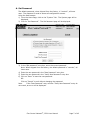
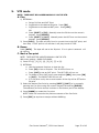
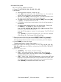
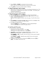
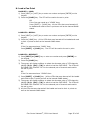
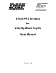
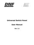
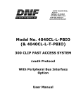
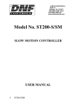
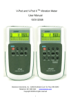
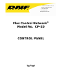
12843 Foothill Blvd. Suite C
Sylmar, California 91342
V: 818.898.3380
F: 818.898.3360
[email protected]
Flex Control Network®
Model No. CP-20
CONTROL PANEL
User Manual
Rev. 1.06
Table of Content
Revision History....................................................................................................... 3
1.
Installation.................................................................................................... 4
Connection Diagram ....................................................................................... 4
2.
IP Configuration ............................................................................................. 5
A. IP Address Setup ..................................................................................... 5
B. Subnet Mask Setup .................................................................................. 5
C. Gateway Address Setup............................................................................ 5
3.
Initial Setup .................................................................................................. 6
A. Set Password .......................................................................................... 7
B. Set System Time ..................................................................................... 8
C. Set System Label .................................................................................... 9
D. Set DNF Port Number ..............................................................................10
E. Set Ethernet Speed.................................................................................11
F. Channel Assignment ...............................................................................12
G. Additional Setups ...................................................................................13
H.
System maintenance ...........................................................................14
4.
Setup menu. .............................................................................................. 17
5.
VTR mode ................................................................................................... 22
A. Play ......................................................................................................22
B. Recue ...................................................................................................22
C. Mark a Cue point ....................................................................................22
D. Learn Cue point......................................................................................23
E. Gang-Temporary (set in menu) ................................................................24
F. Gang-Permanent (set in menu) ................................................................24
G. Set IN and OUT points.............................................................................24
H.
Load a Cue Point .................................................................................25
I.
Recue ...................................................................................................26
J.
Search to ..............................................................................................26
K. Preroll...................................................................................................26
6.
CLIP mode .................................................................................................. 27
A. Load a clip.............................................................................................27
B. Play a clip..............................................................................................27
C. Recue ...................................................................................................27
D. Loop .....................................................................................................28
E. Play to Loop...........................................................................................28
F. Mark a Cue point ....................................................................................29
G. Learn a Cue point ...................................................................................29
H.
Gang-Temporary (set in menu) .............................................................30
I.
Gang-Permanent (set in menu) ................................................................30
J.
Set IN and OUT points.............................................................................30
K. Load a Cue Point ....................................................................................31
L. Recue ...................................................................................................31
M.
Search to ...........................................................................................31
N.
Preroll ...............................................................................................32
O.
Create a clip .......................................................................................32
7.
Shotbox Functions........................................................................................ 33
8.
Shotbox Shotkey Mapping of Cue Point Locations.............................................. 33
9.
Function Table ............................................................................................. 34
10.
Specifications .............................................................................................. 36
11.
Keyboard layout........................................................................................... 37
DNF Controls Limited Warranty ................................................................................ 38
Flex Control Network®, CP20 User Manual
Page 1 of 42
Flex Control Network®, CP20 User Manual
Page 2 of 42
Revision History
020107
1.00
Original document.
020507
1.01
Minor corrections.
091207
1.02
Added new features (channel view, gang function).
091907
1.03
Minor corrections.
072709
1.04
Minor corrections.
081309
1.05
Added IP Configuration.
102510
1.06
Added Shotbox
Document name ............................................................. CP20_User_Manual.doc
Flex Control Network®, CP20 User Manual
Page 3 of 42
1.
Installation
CAUTION
Do NOT apply AC voltage to the power supply, before connecting the power supply to
CP20 CONTROL PANEL. Component damage may occur.
1) Connect a Cat 5 cable to CP20 CONTROL PANEL connector labeled “E-NET #1”.
Connect other end of the Cat 5 cable to customer supplied Ethernet hub.
2) Connect power supply DB9 female connector to the CP20 CONTROL PANEL
connector labeled “POWER“.
3) Connect female side of AC power cable to the supplied power supply.
4) Connect male side of AC power cable to 100 – 240VAC.
5) Push the CONTROL PANEL power switch, located on rear panel, to ON position.
“O” on the power switch is the OFF position.
6) When power up and system initialization completes, the front panel display will
show Model Number and Software Version. Allow 25 seconds for power up and
system initialization to complete.
7) OPTIONAL: Connect PC Keyboard to CP20 CONTROL PANEL connector labeled
“Keyboard”
8) OPTIONAL: Connect ST420 Shotbox to CP20 CONTROL PANEL connector labeled
“RS-232 Port” using the supplied RS232 cable. Use the top connector.
CAUTION
Do NOT apply AC voltage to power supply, then hot plug the power supply to the
CP20 CONTROL PANEL. Component damage may occur.
Connection Diagram
Flex Control Network®, CP20 User Manual
Page 4 of 42
2.
IP Configuration
IP Configuration is required after initial installation.
A.
IP Address Setup
1)
On the CP20 front panel, press [Menu] to enter the setup menu.
2)
Using the shuttle wheel, scroll to the left until the “Current IP Address”
screen is displayed. Display will show current IP address.
3)
Press {New IP} to edit the current IP address.
4)
Using the numeric keypad, enter the desired IP address for the CP20.
5)
Press {SAVE} to save new IP address. Confirmation will be requested
before saving changes. Press {YES} to save the changes, or {NO} to
discard them.
OR
Press {CANCEL} to exit without saving.
NOTE- New IP Address will take effect on next power up.
B.
Subnet Mask Setup
1)
On the CP20 front panel, press [Menu] to enter the setup menu.
2)
Using the shuttle wheel, scroll to the left until the “Current Subnet Mask”
screen is displayed. Display will show current subnet mask.
3)
Press {New Subnet Mask} to edit the current IP address.
4)
Using the numeric keypad, enter the desired subnet mask for the CP20.
5)
Press {SAVE} to save new subnet mask. Confirmation will be requested
before saving changes. Press {YES} to save the changes, or {NO} to
discard them.
OR
Press {CANCEL} to exit without saving.
NOTE- New Subnet Mask will take effect on next power up.
C.
Gateway Address Setup
1)
On the CP20 front panel, press [Menu] to enter the setup menu.
2)
Using the shuttle wheel, scroll to the left until the “Current Gateway”
screen is displayed. Display will show current gateway.
3)
Press {New Gateway} to edit the current IP address.
4)
Using the numeric keypad, enter the desired gateway for the CP20.
5)
Press {SAVE} to save new gateway. Confirmation will be requested
before saving changes. Press {YES} to save the changes, or {NO} to
discard them.
OR
Press {CANCEL} to exit without saving.
NOTE- New Gateway Address will take effect on next power up.
Flex Control Network®, CP20 User Manual
Page 5 of 42
3.
Initial Setup
Setup is required after installation. This step may be performed at any other time,
as required.
Setup is performed using a computer running an off-the-shelf web browser such as
“Microsoft Internet Explorer” or “Netscape”. Connect the CAT5 cable from the
computer to the same Ethernet hub that the CP20 is connected to.
After launching the web browser, enter the IP address of the CP20 to be setup. The
Home Page will be displayed.
Flex Control Network®, CP20 User Manual
Page 6 of 42
A. Set Password
The default password, when shipped from the factory, is “controls”, all lower
case. The password is used to access all configuration screens.
Using the web browser1) From the Home Page, click on the “System” link. The System page will be
displayed.
2) Click on “Set Password”. The Set Password page will be displayed.
3) In the “Old password” entry box, enter the current password.
Note- When shipped from the factory, the default password is “controls”, all
lower case.
4) Enter the new password in the “New Password” entry box.
5) Enter the new password in the “Verify New Password” entry box.
6) Click on “Save” to save the new password.
OR
Click on “Cancel” to exit without changing the password.
NoteIf the “New Password” entry and the “Verify New Password” entry do
not match, an error will be displayed.
Flex Control Network®, CP20 User Manual
Page 7 of 42
B. Set System Time
The system time is only used for error and event time stamping.
Using the web browser1) From the Home Page, click on the “System” link. The System page will be
displayed.
2) Click on “Set System Time”. The Set System Time page will be displayed.
3) Using the drop down menus, set the current date and time.
4) Click on “Save” to save the entered date and time.
OR
Click on “Cancel” to exit without saving.
Flex Control Network®, CP20 User Manual
Page 8 of 42
C. Set System Label
The System Label is used to uniquely identify a CP20. This name is associated
with the IP address.
Using the web browser1) From the Home Page, click on the “System” link. The System page will be
displayed.
2) Click on “Set System Label”. The Set System Label page will be displayed.
3) Enter any name made up of letters, numbers, or special characters, up to 16
characters.
4) Click on “Save” to save the entered name.
OR
Click on “Cancel” to exiting without changing the System Label.
Flex Control Network®, CP20 User Manual
Page 9 of 42
D. Set DNF Port Number
The DNF Port Number is only changed from it default value (50000) when
required to pass through customer firewalls. Please consult your IT department
for a port number value. This setting must match the Port Number setting on all
Flex Control Network units that this product will connect to.
Using the web browser1) From the Home Page, click on the “System” link. The System page will be
displayed.
2) Click on “Set DNF Port Number”. The Set DNF Port Number page will be
displayed.
3) Enter a valid number corresponding to the current system.
4) Click on “Save” to save the entered DNF port number.
OR
Click on “Back” to exit without saving.
Flex Control Network®, CP20 User Manual
Page 10 of 42
E. Set Ethernet Speed
The default password, when shipped from the factory, is “controls”, all lower
case. The password is used to access all configuration screens.
Using the web browser1) From the Home Page, click on the “System” link. The System page will be
displayed.
2) Click on “System Maintenance” Link, the System Maintenance page will be
displayed.
3) Click on “Set Ethernet Speed” Link, the Ethernet Speed Setting page will be
displayed.
4) Click on the Radio button to select the Ethernet speed, and then click on the
Apply button.
OR
Click on the Back button to exit without making any changes.
Flex Control Network®, CP20 User Manual
Page 11 of 42
F. Channel Assignment
The Channel Assignment Table Setup is performed using a computer running an
off-the-shelf web browser such as “Microsoft Internet Explorer” or “Netscape”.
Connect the CAT5 cable from the computer to the same Ethernet hub that the
CONTROL PANEL is connected to.
After launching the web browser, enter the IP address of the CP20 to be setup.
The Home Page will be displayed.
1) Click on the “Channel Assignment” link at the top of the page. The Channel
Assignment Table will be displayed.
2)
Flex Control Network®, CP20 User Manual
Page 12 of 42
3) Click on the “Edit Channel Assignment Table” link at the bottom of the page.
The Edit Channel Assignment Table will be displayed.
4) Click in the Remote IP address field and enter the IP address of the DC20
device controller. Click on the arrow of the dropdown box and select the
remote channel to be connected.
5) Repeat the previous step for each VTR channel.
6) At the bottom of the table enter the IP address for the primary and backup
CUE SERVER (DC20).
7) If used, in the PBIO field, enter the IP address of the DC20 to which the
production switcher is attached.
8) Click on “Save” to save the entered data.
OR
Click on “Back” to exit without saving.
G. Additional Setups
No additional setups are required in “System Maintenance” for normal operation.
Flex Control Network®, CP20 User Manual
Page 13 of 42
H. System maintenance
View event logs
The default password, when shipped from the factory, is “controls”, all lower
case. The password is used to access all configuration screens.
Using the web browser1) From the Home Page, click on the “System” link. The System page will be
displayed.
2) Click on “System Maintenance” Link, the System Maintenance page will be
displayed.
3) Click on “View Event Logs” Link, the Event Logs File List page will be
displayed.
Flex Control Network®, CP20 User Manual
Page 14 of 42
4) Click on a radio button to select the Event File to view. Then click on the
“View Log” button to display the file.
5) Right click on the file name to “Save As” the file to the PC. The file will be
saved as a standard “CSV” (coma separated value) format.
6) Click on the Back button to exit the page.
Flex Control Network®, CP20 User Manual
Page 15 of 42
View System Logs
The default password, when shipped from the factory, is “controls”, all lower
case. The password is used to access all configuration screens.
Using the web browser1) From the Home Page, click on the “System” link. The System page will be
displayed.
2) Click on “System Maintenance” Link, the System Maintenance page will be
displayed.
3) Click on “View System Logs” Link, the System Logs File List page will be
displayed.
4) Double click on the file name to view the file.
5) Right click on the file name to “Save As” the file to the PC.
6) Click on any menu link to exit the View Page Mode.
7) Click on the radio button to select the file for deletion. Then click the Delete
button to delete the selected file.
8) Click on the Back button to exit without deleting the file.
System Snapshot
The default password, when shipped from the factory, is “controls”, all lower
case. The password is used to access all configuration screens.
Using the web browser1) From the Home Page, click on the “System” link. The System page will be
displayed.
2) Click on “System Maintenance” Link, the System Maintenance page will be
displayed.
3) Click on “System Snapshot” Link, the View System Snapshot page will be
displayed.
4) Click the “Display on Screen” radio button or “Send to File” radio button Then
click on the submit button to perform the selected function. The snapshot will
show the system configuration. This is primarily for diagnostic purposes.
Flex Control Network®, CP20 User Manual
Page 16 of 42
4.
Setup menu.
Press the [MENU] key and turn the wheel clockwise to select the setup item. Then
press a {Softkey} to choose the option or use the Keypad to enter a value.
Press Softkey or
{VTR}: To reassign channel #:
Turn the wheel
Press {<-} or {->} to view available devices.
Press {SEL} to assign device to channel #1.
To GANG all available channels:
Press {GANG} to gang all available
channels to channels.
Status is from device assigned to channel
#1.
Press [MENU], then {VTR}, then
{UNGANG} to release the gang function.
Turn wheel to make other menu selections.
VERSION NUMBER
Shows model number and Software version number.
SYSTEM LABEL
This field shows the control panel name assigned
through the browser application.
REC:
{LOCKOUT}: Record function is disabled.
CRASH: Record function will use CRASH MODE for
recording.
{ASSEMBLE}: Record function will use ASSEMBLE
MODE for recording (not available on all protocols).
{INSERT}: Record function will use INSERT MODE for
recording (not available on all protocols).
WIND MODE:
{LATCH}: The fast wind button function will remain
active until another motion button is pressed.
{HOLD}: The fast wind button function will cease as
soon as the fast wind button is released.
{SPEED}: Press softkey to set the maximum fast
wind speed.
SYSTEM ID:
Not changeable
`
Select LOCAL or GLOBAL then press the {YES} key to
clear all CUE points on the selected unit. Press the
{NO} key to not clear the CUE points.
GET GLOBAL CUES
Select {GET} to Pull GLOBAL CUE LIST from Cue List.
Flex Control Network®, CP20 User Manual
Page 17 of 42
MARK CUE:
{CURRENT}: The cue data will be saved in the current
cue point location.
{ADVANCE}: The cue point number will increment by
one and then the cue data will be saved in the cue point
number location.
MARK:
Select the TIME DATA to save into the cue point.
{IN and OUT}: Save IN and OUT points into the cue
point.
{CURRENT}: Save only the CURRENT time into the cue
point. Do NOT save the IN and OUT points in the cue
point.
MARK KEY:
{MARK}: To save only the time CURRENT into the cue
point
{LEARN}: To save IN/OUT points and GANG DATA into the
cue point.
(NOTE- Press SHIFT + MARK to execute the alternate
function)
LOAD KEY:
Select LOAD key mode{GOTO}: Only the SELECTED CHANNEL'S cue point
data will be loaded. This mode does NOT restore the
gang configuration.
{RECALL}: The cue point data will load on all channels
that were part of the original Learn. This mode will
restore the Learned gang configuration.
{REDIRECT}: Load the cue point data for Channels 1 and
2 on the selected channel pair- {1,2}, {3,4}, {5,6}, or
{7,8}. Follow the prompt on the LCD display.
(NOTE- Press SHIFT + LOAD to execute the alternate
function)
GANG:
Select GANG mode.
{TEMPORARY}: Gang Channels by pressing and
holding one [Channel] key, then press and release other
[Channel] keys to add to the gang. Release all
[Channel] keys when done. Press any [Channel] key to
cancel the gang.
{PERMANENT}: Press and hold [SHIFT] and then press
any [Channel] key. Release [SHIFT]. Follow the
prompts on the LCD display. Press a [Channel] key to
add it to the gang. Press the [Channel] key again to
remove it from the gang. Press [SHIFT] when done. The
gang will remain until cancelled by pressing [SHIFT] +
any [Channel] key.
Flex Control Network®, CP20 User Manual
Page 18 of 42
IP ADDRESS DISPLAY:
{ON}: Show IP address on LCD display
{OFF}: Do NOT show IP address on LCD display
(recommended)
REC KEY:
{REC}: Press only the REC key to start record.
{REC + PLAY}: Press and hold REC and then press
PLAY to start record.
PREROLL
Press the [Channel] key and then press {CHANGE}.
Use the numeric keypad to enter the new value. Press
[ENTER] to save the new value. Each Channel has its
own PREROLL value.
POSTROLL
For CAPTURE Function only. Set amount of postroll past
OUT point.
Press the [Channel] key and then press {CHANGE}.
Use the numeric keypad to enter the new value. Press
[ENTER] to save the new value. Each Channel has its
own POSTROLL value.
FAT-IN
For CAPTURE Function only. Set amount of record pad
before IN point.
Press the [Channel] key and then press {CHANGE}.
Use the numeric keypad to enter the new value. Press
[ENTER] to save the new value. Each Channel has its
own FAT-IN value.
FAT-OUT
For CAPTURE Function only. Set amount of record pad
after OUT point.
Press the [Channel] key and then press {CHANGE}.
Use the numeric keypad to enter the new value. Press
[ENTER] to save the new value. Each Channel has its
own FAT-OUT value.
GANG SYNC:
Used to GANG devices located on multiple DC20 Device
Controllers.
{No LTC + Ref Video}: GANG play and record will NOT
be frame accurate across devices connected to different
DC20s.
{With LTC + Ref Video}: GANG play and record will be
frame accurate across devices connected to different
DC20s.
NETWORK DELAY:
Only required when doing frame accurate GANG Play
across devices connected to different DC20s. Please
contact DNF Customer Support prior to changing.
GANG NETWORK
DELAY:
View the network delay of each ganged channel.
Flex Control Network®, CP20 User Manual
Page 19 of 42
CURRENT IP ADDRESS:
View current IP Address. Press softkey to change the
displayed address. Use keypad to enter new address.
The system must be rebooted for the new setting to
take effect.
CURRENT SUBNET
MASK:
View current Subnet Mask. Press softkey to change the
displayed mask address. Use keypad to enter new
address. The system must be rebooted for the new
setting to take effect.
CURRENT GATEWAY:
View current Gateway. Press softkey to change the
displayed gateway address. Use keypad to enter new
address. The system must be rebooted for the new
setting to take effect.
CHANNEL:
Assign devices to the CP20 channel keys.
Press {<-} or {->} keys to select the CP20 channel.
Press {EDIT} Then:
Press {IP} to select DC20, use keypad to enter
IP address. Use {<-} or {->} to position
cursor on IP address field.
Press {CH} to select DC20 device port number.
Use keypad to enter Channel number.
Press {SAVE} to assign device to CP20
channel.
Press {UP} to return to CHANNEL assignment
menu.
Press {LBL} to list all available devices.
Turn wheel to select device then press [ENTER]
to assign device to CP20 channel.
CHANNEL ASSIGNMENT
TABLE:
{BACKUP}: Save the current Channel Assignments to a
file. Enter a file name using the numeric keypad. Or, turn
the wheel to select and overwrite an existing file. Press
[ENTER] to complete the save.
{RESTORE}: Replace the current Channel Assignments
with those saved in the selected file. Enter a file name
using the numeric keypad. Or, turn the wheel to select an
existing file. Press [ENTER] to restore the selected file.
LTC SNAPSHOT:
Diagnostic only.
No LTC Signal: there is no LTC signal connected to the
CP20.
{REFRESH}: Press softkey to refresh the reading.
Flex Control Network®, CP20 User Manual
Page 20 of 42
TIME MODE:
Select channel
Press {TOGGLE} to set time mode.
TM: Display elapsed time from first frame (always
00:00:00:00) of video.
TC: Display Timecode.
VT: Display vertical interval time code data
Flex Control Network®, CP20 User Manual
Page 21 of 42
5.
VTR mode
NOTE: TAPE MUST BE LOADED MANUALLY ON THE VTR.
A. Play
1) OPTIONAL:
a. Set an IN Point and OUT Point.
b. Jog/Shuttle to the desired IN point. Press [IN].
c. Jog/Shuttle to the desired OUT point. Press [OUT].
OR
d. Press [SHIFT] + [IN]. Manually enter the IN time on the numeric
keypad. Press [ENTER].
e. Press [SHIFT] + [OUT]. Manually enter the OUT time on the numeric
keypad. Press [ENTER].
2) Press [PLAY]. The tape will play from its current time to the OUT point, and
then stop. If OUT point is not set then it will play to end of TAPE.
B. Recue
Press [GOTO]. The tape will cue to the IN point. If no in point is entered: will
do nothing.
C. Mark a Cue point
NOTE: TAPE MUST BE LOADED MANUALLY ON THE VTR.
With menu setting: MARK CUE=MARK.
1) Press VTR [1], [2], [3], [4], [5], [6], [7] or [8].
2) OPTIONAL
a. Use the transport functions to view the clip.
b. Press [IN] to set an IN point. The IN LED will turn on.
c. Press [OUT] to set an OUT point. The OUT LED will turn on.
d. To delete an IN or OUT point, press and hold [DEL], then press [IN]
or [OUT]. The IN/OUT LED will turn off.
e. If no IN point is set, the current location of the clip will be SET as the
IN point.
3) Select the desired Cue Point by pressing [NEXT], [LAST] or by manually
entering the Cue Point using the numeric keypad, followed by [ENTER].
The selected Cue Point number is shown on the bottom part of the display.
4) Press [MARK] to create the Cue point.
NOTE: MARK will overwrite the previous contents of the Cue Point.
5) Press [ESC] at anytime to escape without MARKing.
Flex Control Network®, CP20 User Manual
Page 22 of 42
D. Learn Cue point
With menu setting: MARK CUE=LEARN
1) Press VTR [1], [2], [3], [4], [5], [6], [7] or [8].
2) OPTIONAL:
a. Use the transport functions to view the clip.
b. Press [IN] to set an IN point. The IN LED will turn on. On recall, the
clip will cue to the IN time, not the beginning of the clip.
c. Optional- Press [OUT] to set an OUT point. The OUT LED will turn on.
On recall, the clip will play to the OUT point then stop.
d. To delete an IN or OUT point, press and hold [DEL], then press [IN]
or [OUT]. The IN/OUT LED will turn off.
e. If no IN point is set, the current location of the clip will be learned as
the IN point.
f.
For GANG, repeat steps a. through e. for each channel. Then, press
the [SHIFT] + any [VTR] key enter the GANG mode.
Press VTR [1], [2], [3], [4], [5], [6], [7] or [8] to add the VTR to
the GANG. The VTR LED will turn on.
Press the VTR key again to remove it from the gang. The VTR LED will
turn off.
Press [ENTER] to complete the GANG mode. The LED of all GANGed
VTRs will turn on. The primary VTR's LED will flash.
3) Select the desired Cue Point by pressing [NEXT], [LAST] or by manually
entering the Cue Point using the numeric keypad, followed by [ENTER].
The selected Cue Point number is shown on the bottom part of the display.
4) Press [MARK] to initiate the Learn.
The display will show: “Select VTRs to learn: --------”.
5) Select the VTRs to be learned by pressing VTR keys [1], [2], [3], [4], [5],
[6], [7] or [8], press the VTR key a second time to not include it as part of
the LEARN.
6) Select the "play mode":
a. {NORMAL}: Clip will play one time and stop.
b. {2P}: Loop mode (plays from IN point to OUT point; Enter the
number of plays before the loop mode is exited; press [ENTER] to
complete the iteration count entry.
c. {3P}: Play to Loop: (plays from beginning of clip to end or OUT point
and loops to IN point and continues to loop between the IN point and
OUT point; Enter the number of plays before the loop mode is exited;
press [ENTER] to complete the iteration count entry.
Flex Control Network®, CP20 User Manual
Page 23 of 42
7) Press {LRN} or [MARK] to complete the Learn process.
NOTE: Learn will overwrite the previous contents of the Cue Point.
8) Press [ESC] at anytime to escape without LEARNing.
E. Gang-Temporary (set in menu)
1) Press all the VTR keys that are to be part of the Gang at the same time. The
LEDs will light to indicate that they are part of the GANG. The flashing LED
indicates the selected VTR.
2) Press any VTR key to cancel the GANG.
F. Gang-Permanent (set in menu)
1) Press the [SHIFT] key + any [VTR] key to start the gang dialogue.
2) Press VTR [1], [2], [3], [4], [5], [6], [7] or [8] to add the VTR to the
GANG. The VTR LED will turn on.
Press the VTR key again to remove it from the gang. The VTR LED will turn
off.
3) Press [SHIFT] to complete the GANG mode. The LEDs of all GANGed VTRs
will turn on and the selected VTR LED will flash.
4) To CANCEL the gang function:
Press the [SHIFT] key + any [VTR] key to start the gang dialogue.
Press the {CLEAR} key to cancel the gang function.
G. Set IN and OUT points
1) Set an IN Point and/or OUT Point.
Jog/Shuttle to the desired IN Point. Press [IN].
Jog/Shuttle to the desired OUT Point. Press [OUT].
2) Press [IN] to set an IN point. The IN LED will turn on. Optional- Press
[OUT] to set an OUT point. The OUT LED will turn on.
Press [SHIFT] + [IN]. Manually enter the IN time on the numeric keypad.
Press [ENTER].
Press [SHIFT] + [OUT]. Manually enter the OUT time on the numeric
keypad. Press [ENTER].
3) To delete an IN or OUT point, press and hold [DEL], then press [IN] or
[OUT]. The IN/OUT LED will turn off.
Flex Control Network®, CP20 User Manual
Page 24 of 42
H. Load a Cue Point
LOAD KEY = LOAD
1) Press [NEXT] or [LAST] key or enter cue number and press [ENTER] on the
keypad
2) Press the [LOAD] key. The VTR will be cued to the set in point.
OR
If the Cue was saved as a "LEARN" then:
Press [SHIFT] + [LOAD] key. All the VTRs that were learned will
be loaded and cued to their in points as well as the learned GANG
states.
LOAD KEY = RECALL
1) Press [NEXT] or [LAST] key or enter cue number and press [ENTER] on the
keypad
2) Press the [LOAD] key. All the VTRs that were learned will be loaded and cued
to their in points as well as the learned GANG states.
OR
If the Cue was saved as a "MARK" then:
Press [SHIFT] + [LOAD] key. The VTR will be cued to the set in point.
LOAD KEY = REDIRECT
1) Press [NEXT] or [LAST] key or enter cue number and press [ENTER] on
the keypad
2) Press the [LOAD] key.
3) The screen will display softkeys to select the alternate pairs of VTR channels
{1,2}; {3,4}; {5,6}; {7,8} to which to load the CUE POINT. The VTRs will
be loaded from channels 1 & 2 to the selected pair of channels and cued to
the set in point.
OR
If the Cue was saved as a "LEARN" then:
1) Press [SHIFT] + [LOAD] key. (All the VTRs that were learned will be loaded
and cued to their in points as well as the learned GANG states).
2) The screen will display softkeys to select the alternate pairs of VTR channels:
{1,2}; {3,4}; {5,6}; {7,8} to which to load the CUE POINT. The VTRs will
be loaded from channels 1 & 2 to the selected pair of channels and cued to
the set in point.
3) All the VTRs that were learned will be loaded and cued to their in points as
well as the learned GANG states.
Flex Control Network®, CP20 User Manual
Page 25 of 42
I. Recue
Press [GOTO]. If an IN Point is set (the IN indicator is on), the VTR will RECUE
to the IN Point. If no IN point is set then do nothing.
J. Search to
1) Press [SHIFT] + [GOTO] then enter the search point on the keypad and press
[ENTER] to cue to the entered time.
2) Press [SHIFT] + [IN] then [GOTO] will cue to the in point.
3) Press [SHIFT] + [OUT] then [GOTO] will cue to the out point.
K. Preroll
Press [PREROLL] to cue to the amount of time preset in the menu before the
current position. If an IN point was set it will cue to the preset amount before
the in point.
Flex Control Network®, CP20 User Manual
Page 26 of 42
6.
CLIP mode
A. Load a clip
1) Select a VTR by pressing VTR [1], [2], [3], [4], [5], [6], [7] or [8].
2) Press [CLIP LIST] to view the list of CLIP IDs that are resident on the Video
Server. The CLIP LIST indicator will turn on. Turn the Wheel clockwise to
scroll forward, or counter-clockwise to scroll backward, through the list of
available CLIPs. Backward scrolling is limited to the last 10 screens of CLIP
IDs viewed.
OR
Manually enter a CLIP ID using the CP20 numeric keypad, or PC keyboard.
3) Press [LOAD] to load the entered CLIP ID for playout.
4) Repeat steps 1) thru 3) to load clips on other VTRs.
5) Set the Gang Mode, if required. See “GANG SETUP” in “FUNCTION TABLE”
section.
B. Play a clip
1) OPTIONAL:
a.
Set an IN Point and OUT Point.
b.
Jog/Shuttle to the desired IN point. Press [IN].
c.
Jog/Shuttle to the desired OUT point. Press [OUT].
OR
d.
Press [SHIFT] + [IN]. Manually enter the IN time on the
numeric keypad. Press [ENTER].
e.
Press [SHIFT] + [OUT]. Manually enter the OUT time on the
numeric keypad. Press [ENTER].Press [PLAY]. The clip will
play from its current time to the OUT point, and then stop. If
OUT point is not set then it will play to end of clip.
2) Press [PLAY], the clip will play from its current position to the out point, and
then stop. If out point is not set, then play to the end of the clip.
C. Recue
Press [GOTO]. The clip will cue to the IN point. If no IN point is set then cue to
beginning of clip.
Flex Control Network®, CP20 User Manual
Page 27 of 42
D. Loop
1) Load the clip using LOAD A CLIP, or LOAD a cue point.
2) OPTIONAL:
a. Set an IN Point and/or OUT Point.
b. Jog/Shuttle to the desired IN Point. Press [IN].
c. Jog/Shuttle to the desired OUT Point. Press [OUT].
OR
a. Press [SHIFT] + [IN]. Manually enter the IN time on the numeric
keypad. Press [ENTER].
b. Press [SHIFT] + [OUT]. Manually enter the OUT time on the numeric
keypad. Press [ENTER].
NOTE: To loop the whole clip, do not enter IN/OUT.
3) Press [LOOP ENABLE]. The clip will immediately start looping.
NOTE: If the clip ID ends with an asterisk (“*”), it will automatically loop when
[PLAY] is pressed.
E. Play to Loop
The PLAY TO LOOP function will start from the beginning of the clip play to the
out point (or to the end of clip if out point is not set) and then loop to the in point
and continue to loop between the in and the out points (or to the end of the clip
if out point is not set).
1) Load the clip using LOAD A CLIP, or LOAD a Cue Point.
2) Set an IN Point and/or OUT Point.
a. Jog/Shuttle to the desired IN Point. Press [IN].
b. Jog/Shuttle to the desired OUT Point. Press [OUT].
OR
a. Press [SHIFT] + [IN]. Manually enter the IN time on the numeric
keypad. Press [ENTER].
b. Press [SHIFT] + [OUT]. Manually enter the OUT time on the numeric
keypad. Press [ENTER].
3) Press [SHIFT] + [LOOP ENABLE]. The clip will immediately cue to beginning
of the clip and the LOOP ENABLE LED will start blinking.
4) Press [PLAY] to start the PLAY TO LOOP.
NOTE: If the clip ID ends with an asterisk (“#”), it will automatically perform A
PLAY TO LOOP when [PLAY] is pressed.
Flex Control Network®, CP20 User Manual
Page 28 of 42
F. Mark a Cue point
With menu setting: MARK CUE=MARK.
1) Press VTR [1], [2], [3], [4], [5], [6], [7] or [8].
2) Load a clip on the selected channel. See section LOAD A CLIP.
3) OPTIONAL:
a. Use the transport functions to view the clip.
b. Press [IN] to set an IN point. The IN LED will turn on. On recall, the
clip will cue to the IN time, not the beginning of the clip.
c. Press [OUT] to set an OUT point. The OUT LED will turn on. On recall,
the clip will play to the OUT point then stop.
d. To delete an IN or OUT point, press and hold [DEL], then press [IN] or
[OUT]. The IN/OUT LED will turn off.
e. If no IN point is set, the current location of the clip will be MARKED as
the IN point.
4) Select the desired Cue Point by pressing [NEXT], [LAST] or by manually
entering the Cue Point using the numeric keypad, followed by [ENTER].
The selected Cue Point number is shown on the bottom part of the display.
5) Press [MARK] to create the Cue point.
NOTE: Play mode is defaulted to "NORMAL" (no loop) for all MARKed cue
points. MARK will overwrite the previous contents of the Cue Point.
6) Press [ESC] at anytime to escape without MARKing.
G. Learn a Cue point
With menu setting: MARK CUE=LEARN.
1) Press VTR [1], [2], [3], [4], [5], [6], [7] or [8].
2) Load a clip on the selected channel. See section LOAD A CLIP
3) OPTIONAL:
a. Use the transport functions to view the clip.
b. Press [IN] to set an IN point. The IN LED will turn on. On recall, the
clip will cue to the IN time, not the beginning of the clip.
c. Optional- Press [OUT] to set an OUT point. The OUT LED will turn on.
On recall, the clip will play to the OUT point then stop.
To delete an IN or OUT point, press and hold [DEL], then press [IN] or
[OUT]. The IN/OUT LED will turn off.
If no IN point is set, the current location of the clip will be learned as
the IN point.
d. For GANG, repeat steps a. through c. for each channel. Then, press
the [SHIFT] + any [VTR] key enter the GANG mode.
e. Press VTR [1], [2], [3], [4], [5], [6], [7] or [8] to add the VTR to the
GANG. The VTR LED will turn on.
f.
Press the VTR key again to remove it from the gang. The VTR LED will
turn off.
g. Press [ENTER] to complete the GANG mode. The LED of all GANGed
VTRs will turn on. The primary VTR's LED will flash.
4) Select the desired Cue Point by pressing [NEXT], [LAST] or by manually
entering the Cue Point using the numeric keypad, followed by [ENTER].
5) The selected Cue Point number is shown on the bottom part of the display.
6) Press [MARK] to initiate the Learn.
Flex Control Network®, CP20 User Manual
Page 29 of 42
7) The display will show: “Select VTRs to learn: --------”.
8) Select the VTRs to be learned by pressing VTR keys [1], [2], [3], [4], [5],
[6], [7] or [8], press the VTR key second time to not include it as part of the
LEARN.
9) Select the "play mode":
a. {NORMAL}: Clip will play one time and stop.
b. {2P}: Loop mode (plays from IN point to OUT point; Enter the
number of plays before the loop mode is exited; press [ENTER] to
complete the iteration count entry.
c. {3P}: Play to Loop: (plays from beginning of clip to end or OUT point
and loops to IN point and continues to loop between the IN point and
OUT point; Enter the number of plays before the loop mode is exited;
press [ENTER] to complete the iteration count entry.
10) Press {LRN} or [MARK] to complete the Learn process.
NOTE: Learn will overwrite the previous contents of the Cue Point.
11) Press [ESC] at anytime to escape without LEARNing.
H. Gang-Temporary (set in menu)
1) Press all the VTR keys that are to be part of the Gang at the same time. The
LEDs will light to indicate that they are part of the GANG. The flashing LED
indicates the selected VTR.
2) Press any VTR key to cancel the GANG.
I. Gang-Permanent (set in menu)
1) Press the [SHIFT] key + any [VTR] key to start the gang dialogue.
2) Press VTR [1], [2], [3], [4], [5], [6], [7] or [8] to add the VTR to the GANG.
The VTR LED will turn on.
Press the VTR key again to remove it from the gang. The VTR LED will turn
off.
3) Press [SHIFT] to complete the GANG mode. The LEDs of all GANGed VTRs
will turn on and the selected VTR LED will flash.
To CANCEL the gang function:
4) Press the [SHIFT] key + any [VTR] key to start the gang dialogue.
5) Press the {CLEAR} key to cancel the gang function.
J. Set IN and OUT points
1) Set an IN Point and/or OUT Point.
Jog/Shuttle to the desired IN Point. Press [IN].
Jog/Shuttle to the desired OUT Point. Press [OUT].
2) Press [IN] to set an IN point. The IN LED will turn on. On recall, the clip will
cue to the IN time, not the beginning of the clip.
3) Optional- Press [OUT] to set an OUT point. The OUT LED will turn on. On
recall, the clip will play to the OUT point then stop.
OR
a. Press [SHIFT] + [IN]. Manually enter the IN time on the numeric
keypad. Press [ENTER].
b. Press [SHIFT] + [OUT]. Manually enter the OUT time on the numeric
keypad. Press [ENTER].
To delete an IN or OUT point, press and hold [DEL], then press [IN] or [OUT].
The IN/OUT LED will turn off.
Flex Control Network®, CP20 User Manual
Page 30 of 42
K. Load a Cue Point
LOAD KEY = LOAD
1) Press [NEXT] or [LAST] key or enter cue number and press [ENTER] on the
keypad
2) Press the [LOAD] key. The clip will be cued to the set in point.
OR
3) If the Cue was saved as a "LEARN" then:
4) Press [SHIFT] + [LOAD] key. All the VTRs that were learned will be loaded
and cued to their in points as well as the learned GANG states.
LOAD KEY = RECALL
1) Press [NEXT] or [LAST] key or enter cue number and press [ENTER] on the
keypad
2) Press the [LOAD] key. All the VTRs that were learned will be loaded and
cued to their in points as well as the learned GANG states.
3) OR
4) If the Cue was saved as a "MARK" then:
5) Press [SHIFT] + [LOAD] key. The clip will be cued to the set in point.
LOAD KEY = REDIRECT
1) Press [NEXT] or [LAST] key or enter cue number and press [ENTER] on
the keypad
2) Press the [LOAD] key.
3) The screen will display softkeys to select the alternate pairs of VTR channels:
{1,2}; {3,4}; {5,6}; {7,8} to which to load the CUE POINT. The clips will
be loaded from channels 1 & 2 to the selected pair of channels with the clip
cued to the beginning of clip or to set in point.
OR
4) If the Cue was saved as a "LEARN" then:
5) Press [SHIFT] + [LOAD] key. (All the VTRs that were learned will be loaded
and cued to their in points as well as the learned GANG states).
6) The screen will display softkeys to select the alternate pairs of VTR channels:
{1,2}; {3,4}; {5,6}; {7,8} to which to load the CUE POINT. The VTRs will
be loaded from channels 1 & 2 to the selected pair of channels with the clip
and cued to the beginning of clip or to set in point.
7) All the VTRs that were learned will be loaded and cued to their in points as
well as the learned GANG states.
L. Recue
Press [GOTO]. If an IN Point is set (the IN indicator is on), the clip will RECUE
to the IN Point.
If the IN point is not set, the clip will RECUE to the start of the clip.
M. Search to
1) Press [SHIFT] + [GOTO] then enter the search point on the keypad to cue to
the entered time.
2) Press [SHIFT] + [IN] then [GOTO] will cue to the in point.
3) Press [SHIFT] + [OUT] then [GOTO] will cue to the out point.
Flex Control Network®, CP20 User Manual
Page 31 of 42
N. Preroll
Press [PREROLL] to cue to the amount preset in the menu before the current
position. If an in point was set it will then cue to the preset amount before the in
point.
O. Create a clip
1) Press [CLIP LIST].
2) Press [CREATE].
3) Manually enter an ID from the CP20 numeric keypad.
OR
Manually enter an ID from a PC keyboard.
4) Press [LOAD]. The clip will be created and loaded. If the entered CLIP ID
already exists, a warning message will be displayed.
5) To load the existing clip, press [ENTER].
6) Press [REC] or [REC] + [PLAY] keys to start the record process.
OR
7) Press [ESC] to exit without loading the existing clip.
Flex Control Network®, CP20 User Manual
Page 32 of 42
7.
Shotbox Functions
NOTE: Using the ST420 Shotbox with the CP20 Control Panel requires the following
software versions:
CP20: V6.23A or later
ST420: V4.14 102910 or later
[PLAY]: Plays out the selected clip.
[RECUE]: Returns to the beginning of the clip.
[STOP]: Stops playout of the clip.
[LEARN]: Press to initiate the shotbox learn function.
[ESC]: Cancel an activated function.
8.
Shotbox Shotkey Mapping of Cue Point Locations
The Shotkeys on the Shotbox access the cue point locations in the CP20 as follows:
BANK 0, Shotkeys 1 -> 30 access cue point locations 001 - 030.
BANK 1, Shotkeys 1 -> 30 access cue point locations 101 - 130.
BANK 2, Shotkeys 1 -> 30 access cue point locations 201 - 230.
BANK 3, Shotkeys 1 -> 30 access cue point locations 301 - 330.
BANK 4, Shotkeys 1 -> 30 access cue point locations 401 - 430.
BANK 5, Shotkeys 1 -> 30 access cue point locations 501 - 530.
BANK 6, Shotkeys 1 -> 30 access cue point locations 601 - 630.
BANK 7, Shotkeys 1 -> 30 access cue point locations 701 - 730.
BANK 8, Shotkeys 1 -> 30 access cue point locations 801 - 830.
BANK 9, Shotkeys 1 -> 30 access cue point locations 901 - 930.
Flex Control Network®, CP20 User Manual
Page 33 of 42
9.
Function Table
Function
Key Press
Description
CLIP LIST
[CLIP LIST]
Press the [CLIP LIST] key to access the clip list
on the server.
FFWD
[FFWD]
Press and HOLD to shuttle. Release key to stop.
Set WIND Speed in MENU.
GANG RE-SYNC
[SHIFT] + [STOP]
Press and hold the [SHIFT] key and press the
[STOP] key. This will reestablish the time offset
to the ganged channels. After multiple
play/stop, jog or shuttle operations the offset
between the ganged channels can be off by
several frames.
GANG SETUP
[SHIFT] + [any VTR key]
Individually press the VTR keys to be included in
the gang. The LED above the key will turn on.
Press the VTR key again to remove from gang.
The LED above the key will turn off. Press
[ESC] to exit. Upon exiting, all members of the
gang will have their VTR LEDs turned on. The
flashing LED shows which VTR is currently
selected.
VTR KEYS
(SIMULTANEOUSLY)
Press all the VTR keys that are to be part of the
GANG at the same time. The LEDs of the
ganged channels will be on. The first key held
down will be the selected VTR, its LED will flash.
(PERMANENT)
GANG SETUP
(TEMPORARY)
Press any one of the GANGED VTR keys to
cancel the GANG
GOTO ENTERED
TIME
[SHIFT] + [GOTO]
Search the VTR to the manually entered time.
Use the CP20 numeric keypad. Press [ENTER]
or [GOTO].
GOTO IN POINT
[GOTO]
If IN point is set, cue to the IN point.
GOTO OUT POINT
[SHIFT] + [OUT] then
[GOTO]
If OUT point is set, cue to the OUT point.
JOG
[JOG]
Select JOG mode and enable Wheel.
LAST CUE
[LAST]
Step to the previous Cue Point Location.
LOAD AND CUE TO
PREROLL
[SHIFT] + [PREROLL]
Press to load cue and cue to preroll point.
Lock VTR to Panel
[SHIFT] + [MENU]
Press to lock selected VTR to this control panel.
Other control panel cannot access this VTR.
LOOP
[LOOP ENABLE]
Plays the currently loaded clip in a continuous
loop. If in and out points are set then loop
within those points.
PLAY TO LOOP
[SHIFT] + [LOOP ENABLE]
IN point must be set. Press [SHIFT] + [LOOP
ENABLE] to cue to beginning of clip. Then
[PLAY] to start PLAY TO LOOP function. Clip
will play from beginning to end and then
continue to loop from in point to out point.
MENU
[MENU]
Press the [MENU] key to access the menu
items.
Flex Control Network®, CP20 User Manual
Page 34 of 42
NEXT CUE
[NEXT]
Step to the next Cue Point Location.
PLAY
[PLAY]
If an OUT point is set, play to the OUT point and
stop. If not OUT point is set, play normally.
Play past OUT point
[SHIFT] + [PLAY]
Press to force the channel to continue to play
past the OUT point (to end of clip).
PREROLL
[PREROLL]
Cues the clip to IN point - PREROLL time. Preroll
time is set in menu.
RECORD
[REC]
Places VTR into the Record mode selected by
RECORD MODE in the SETUP MENU. Press
[RECORD] or [SHIFT] + [RECORD].
RECUE
[GOTO]
If the IN point is set, cue to the IN point. If the
IN point is not set then cue to beginning of clip.
REWIND
[RWD]
Press and HOLD to shuttle. Release key to stop.
Set WIND Speed in MENU.
SET IN POINT
[IN]
Press the [IN] key to set the in point to the
current position.
SET OUT POINT
[OUT]
Press the [OUT] key to set the out point to the
current position.
SET PBIO
PARAMETERS
[SHIFT] + [PBIO]
Press to set the Pbus address and IP address.
See manual.
SHUTTLE
[SHUT]
Select SHUTTLE mode and enable Wheel.
SLO-MO SPEED
PRESET
[SHIFT] + [SLOMO]
For WHEEL ONLY: Press [SHIFT] + [SLOMO]
to preset the slo-mo speed. Turn the Wheel to
select desired speed. Press [ESC] or any
transport key to exit.
SLOW MOTION
[SLOMO]
Press the [SLOMO] key to start play at speed
set by wheel or by [SHIFT] + [SLOMO]. If
slomo set to zero then still frame. Press any
transport key to exit SLOMO.
STOP
[STOP]
Press once to STILL frame VTR. Press again to
put VTR into STOP mode.
TSO -
[PLAY] + [RWD]
Press and hold [PLAY] and press [RWD] to
play at less than play speed (speed set in menu,
max 25%).
TSO +
[PLAY] + [FFWD]
Press the and hold [PLAY] and press [FFWD]
to play at higher than play speed (speed set in
menu, max 25%).
View Cue Data
[SHIFT] + [NEXT]
Press to view IN point, OUT point, and GANG
data.
[SHIFT] + [LAST]
Press to view LEARN or MARK data
Flex Control Network®, CP20 User Manual
Page 35 of 42
10. Specifications
Power: 90 VAC - 240 VAC power supply, APX #4108, supplied with IEC connector
Size:
(H.W.D.) Front 2 in. Rear 3 3/4 in. X 12 1/4 in. x 7 in.
Weight: 7 lbs
Front Panel Display: 4 line x 20 character liquid crystal display.
Front Panel Keyboard: 47 keys + Wheel.
Serial Port: D9M connector
Not Used
LTC: 3 pin Phoenix Connector
Balanced:
Pin 1 = LTC HI
Pin 2 = LTC LOW
Pin 3 = Common/Shield
Unbalanced:
Pin 1 = LTC HI
Pin 2 = Tie to Pin 3
Pin 3 = Shield
VGA Port: D15HDF connector
E – Net #1: RJ45 Connector
E – Net #2: RJ45 Connector
Not Used
USB #1: USB “A” socket Connector
Not Used
USB #2: USB “A” socket Connector
Not Used
Power Connector: 9-Pin Male (D9M)
Pin #
Function
Pin #
1
+5vdc
6
2
+5vdc
7
3
Ground
8
4
+12vdc
9
5
-12vdc
Function
+5vdc
Ground
Ground
Ground
Serial Port: 9-Pin Female (D9F)
Pin #
Function
Pin #
1
DCD
6
2
RXD
7
3
TXD
8
4
DTR
9
5
Ground
Not Used
Function
DSR
RTS
CTS
RI
Flex Control Network®, CP20 User Manual
Page 36 of 42
11. Keyboard layout
Flex Control Network®, CP20 User Manual
Page 37 of 42
DNF Controls Limited Warranty
DNF Controls warrants its product to be free from defects in material and workmanship for a
period of one (1) year from the date of sale to the original purchaser from DNF Controls.
In order to enforce the rights under this warranty, the customer must first contact DNF’s
Customer Support Department to afford the opportunity of identifying and fixing the
problem without sending the unit in for repair. If DNF’s Customer Support Department
cannot fix the problem, the customer will be issued a Returned Merchandise Authorization
number (RMA). The customer will then ship the defective product prepaid to DNF Controls
with the RMA number clearly indicated on the customer’s shipping document. The
merchandise is to be shipped to:
DNF Controls
12843 Foothill Blvd., Suite C
Sylmar, CA 91342
USA
Failure to obtain a proper RMA number prior to returning the product may result in the
return not being accepted, or in a charge for the required repair.
DNF Controls, at its option, will repair or replace the defective unit. DNF Controls will return
the unit prepaid to the customer. The method of shipment is at the discretion of DNF
Controls, principally UPS Ground for shipments within the United States of America.
Shipments to international customers will be sent via air. Should a customer require the
product to be returned in a more expeditious manner, the return shipment will be billed to
their freight account.
This warranty will be considered null and void if accident, misuse, abuse, improper line
voltage, fire, water, lightning, or other acts of God damaged the product. All repair parts
are to be supplied by DNF Controls, either directly or through its authorized dealer network.
Similarly, any repair work not performed by either DNF Controls or its authorized dealer
may void the warranty.
After the warranty period has expired, DNF Controls offers repair services at prices listed in
the DNF Controls Price List. DNF Controls reserves the right to refuse repair of any unit
outside the warranty period that is deemed non-repairable.
DNF Controls shall not be liable for direct, indirect, incidental, consequential or other types
of damage resulting from the use of the product.
###
Flex Control Network®, CP20 User Manual
Page 38 of 42