1
Important Product Information
GFK-2714P
November 2014
PACSystems* RX3i Central Processing Unit IC695CPE305-ACAN,
Firmware Version 8.30
Product Documentation
PACSystems RX3i and RX7i CPU Reference Manual, GFK-2222
PACSystems RX3i System Manual, GFK-2314
PACSystems RX3i IC695CPE305 CPU Quick Start Guide, GFK-2934
PACSystems RX7i & RX3i TCP/IP Ethernet Communications User Manual, GFK-2224
PACSystems TCP/IP Ethernet Communications Station Manager User Manual, GFK-2225
User manuals, product updates and other information sources are available on the GE Intelligent Platforms Support
website, http://www.ge-ip.com/support, under Controllers and IO, RX3i Controllers.
Release Overview
This release of the product is a firmware-only upgrade which adds support for EGD Class 1 on Embedded Ethernet
Interface.
Upgrades
CPE305 can be upgraded to firmware release 8.30 in the field by installing the USB flash drive upgrade kit
41G1733-MS10-000-A7, which can be downloaded from http://www.ge-ip.com/support.
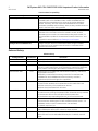
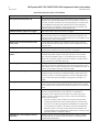
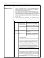
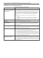
CPU Functional Compatibility
CPU Functional Compatibility
Subject
Description
Proficy* Machine Edition Logic
Developer Version Requirements
Support for EGD on Embedded Ethernet
Interface
8.50 SIM7 or later
CPU Backward Compatibility
Legacy CPU310 Projects are not supported on the CPE305.
C Toolkit Compatibility
C Toolkit version 7.00 or later
The C Toolkit for PACSystems is distributed with Proficy Machine Edition
Logic Developer. Updates can be downloaded from
http://www.ge-ip.com/support.
Note: All C blocks must be recompiled using the new toolkit before
downloading to a release 7.00 or later CPU.
The Series 90 Toolkit (IC641SWP709/719) is not compatible with
PACSystems.
Backplanes, power supplies and
system modules
As listed in the PACSystems RX3i System Manual, GFK-2314.
Power Sync and Measurement module, IC694PSM001
Series 90-30 Main Rack Compatibility
Series 90-30 Main Racks cannot be used in a PACSystems RX3i system.
Series 90-30 CPUs do not operate in PACSystems RX3i Racks.
Isolated 24V power
In applications that use the IC69xALG220/221/222, consult PACSystems
RX3i Hardware and Installation Manual, GFK-2314 for details of wiring the
24V power.
* Indicates a trademark of General Electric Company and/or its subsidiaries. All other trademarks are the property of their respective
owners.
Copyright © 2011-2014 by General Electric Company. All Rights Reserved
PACSystems RX3i CPU IC695CPE305-ACAN Important Product Information
2
GFK-2714P
November 2014
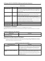
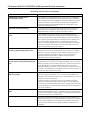
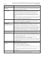
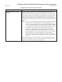
CPU Functional Compatibility
Subject
COMMREQ to PBM300
Description
In Release 3.0, the behavior of the COMMREQ fault output on a
COMMREQ sent to the PROFIBUS master module IC695PBM300 was
changed to be compatible with the Series 90-30 CPU366 PROFIBUS
Master. Previously, the fault output was enabled when the module
received a COMMREQ and it was busy. Now, the busy condition does not
result in the fault output being enabled.
Recommended IC200ALG240 revision
When a VersaMax* system Genius* Network Interface Unit (IC200GBI001)
operates with a Genius Bus Controller located in an RX3i, and the
VersaMax system contains an IC200ALG240 Analog Input Module, it is
recommended to update the IC200ALG240 firmware to Revision 1.10 or
later.
Upgrade kits are available at http://www.ge-ip.com/support.
Configuration of IC694MDL754
Always configure 16 bits of module status when using this module.
Configuring 0 bits of module status will result in invalid data in the
module’s ESCP status bits.
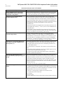
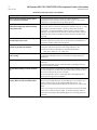
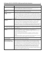
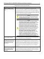
Release History
Release History
Catalog Number
FW Version
Comments
IC695CPE305-ACAN
8.30
Adds support for EGD Class 1 on Embedded Ethernet Interface.
IC695CPE305-ACAM
8.20
Adds support for OPC UA.
IC695CPE305-ACAL
8.15
Replaces the module’s plastic housing with a metal case, improving noise
immunity, reducing emissions, and increasing the mechanical robustness
of the product. No change to the module’s firmware or functionality.
IC695CPE305-ABAL
8.15
Adds support for IC695RMX228 (128 MB Reflective Memory Module with
Single Mode Transceiver.)
Adds ability to read reflective memory status bits for IC695CMX128,
IC695RMX128, and IC695RMX228 (reflective memory modules).
Adds enhanced Ethernet diagnostics capabilities.
IC695CPE305-ABAK
8.05
IC695CPE305-ABAJ
7.80
IC695CPE305-ABAH
7.75
Adds support for the new IC695ECM850 (IEC 61850 Ethernet
Communication Module), which operates as an IEC 61850 Client and
provides connectivity to IEC 61850 Server devices.
Resolves three issues detailed in IPI below.
Resolves the following issues:
• Unable to enter existing CPU password after Enhanced Security enabled.
• The PNC0001 fails to reconnect after remote IO power loss.
• The PBM300 stops responding after SUS_IO instruction executed.
Corrects issues with the OEM lock functionality and with Ethernet
communications. Adds support for RX3i CMX/RMX modules version –CG
(hardware version Cx with firmware version 2.00 and later).
For details, see GFK-2714.
IC695CPE305-ABAG
7.70
Adds support for the following new modules: IC694MDL758, IC695CNM001
and IC694PSM001. Refer to GFK-2714G for issues resolved.
IC695CPE305-ABAF
7.30
Adds support for Modbus/TCP Server, Modbus/TCP Client, SRTP Server, and
SRTP Channels from the embedded Ethernet port. For details, see GFK2224L.
PACSystems RX3i CPU IC695CPE305-ACAN Important Product Information
GFK-2714P
3
November 2014
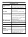
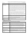
Release History
Catalog Number
FW Version
Comments
IC695CPE305-ABAE
7.16
Adds the ability to write DTR and read DSR, DCD, and RI on CPE310 Serial
Port 1. This functionality has been implemented (for all CPUs with RS-232
Serial ports) using COMREQ 4304 (Write Port Control) and COMREQ 4303
(Read Port Status).
IC695CPE305-ABAD
7.15
Adds native support for the new Power Sync and Measurement module
(IC694PSM001) and resolves several issues. Also introduces new features
to augment security in the CPU firmware and Proficy Machine Edition
software. For details, see GFK-2713D.
IC695CPE305-ABAC
7.14
Corrects an issue where executing a Run Mode Store, displaying the
Proficy Machine Edition Show Status window, or requesting data using the
PACSAnalyzer tool could cause discrete output modules to unexpectedly
change state momentarily (up to one PLC scan).
Corrects an issue that was introduced in release 7.13, which prevented
configuration of Modbus TCP on Ethernet modules.
IC695CPE305-ABAC
7.13
Corrects issues with Logic Write to Flash (Service Request 57).
IC695CPE305-ABAB
7.11
Resolves the issues detailed in GFK-2713A.
IC695CPE305-AAAA
7.10
Initial release.
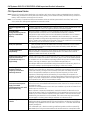
New Features in This Release
Firmware Release 8.30 provides support for EGD class 1 on Embedded Ethernet Interface.
Note: Refer to GFK-2224M, Ethernet Communications Manual, the Chapter on Ethernet Global Data for more details
Problems Resolved by This Release
Resolved Issue
Description
None, firmware-only upgrade which adds
support for EGD Class 1.
N/A
Restrictions and Open Issues in This Release
Note: Ethernet functionality described below only applies to Rx3i CPUs that provide an embedded Ethernet interface.
Additionally, because the CPE310 does not utilize a battery, items related to battery backed memory and/or the
battery itself have been removed from this section.
Restrictions and Open Issues in This Release
Restriction/Open Issue
Description
Serial I/O Half Duplex Mode Failures at
Low Baud Rates
When the CPE305 or CPE310 serial port is configured for Serial I/O
protocol with 2-wire half-duplex serial port mode with baud rates less
than 19.2kBaud, the last transmitted character may end up as the
first character in the receive message buffer upon switching from
transmitting to receiving.
Rare Power-Up Problem on CPE305 and
CPE310
When the CPE305 or CPE310 has logic and configuration source set to
flash, in rare instances the controller will power up with all LEDs
blinking in unison and the controller will be unreachable. An additional
power down and then power up cycle will allow the controller to
completely power up.
4
PACSystems RX3i CPU IC695CPE305-ACAN Important Product Information
GFK-2714P
November 2014
Restrictions and Open Issues in This Release
Restriction/Open Issue
Description
Missing “Addition of IOC” event when
ECM850 module restarts due to reset
pushbutton or SVC_REQ 24
When ECM850 module RESET is triggered using SVC_REQ 24 or Reset
pushbutton, CPU does not report “Addition of IOC” fault message in
Controller fault table after successful reset of module.
Flash part issue on CPE305/CPE310
modules shipped in 2012
When the CPE305 or CPE310 powers down with an Energy Pack
connected, all user memory is written out to the NVS flash device. In
2012, GE Intelligent Platforms received a batch of flash memory chips
that exhibited longer write times, which exceeded the capabilities of
the Energy Pack. This will resulted in the CPE310 not retaining memory
during a power-cycle event and logging a “User memory not
preserved” fault.
The parts that exhibit the extended write times went obsolete in 2012.
Units shipped after January 1st, 2013 or prior to 2012 do not have the
substandard part.
Units shipped in 2012 that exhibit the symptoms of the issue (“User
memory not preserved” fault after power cycle with a working Energy
Pack) can be replaced via the warranty return policy.
Ethernet COMMREQs not always delivered
on the first logic sweep
In certain instances where User Logic is of sufficient size and a
COMMREQ is issued on first logic sweep, the COMMREQ may be
aborted before its transmission is attempted. The condition is much
more observable on COMMREQs issued from the CPU’s embedded
Ethernet port. To avoid the possibility of encountering this condition,
users should avoid issuing COMMREQs on first logic sweep.
PMM335 loss is occasionally detected on
power down of the CPU. (Module is not
lost on power-up.)
The PMM335 PACMotion Multi-axis Motion Controller monitors power
loss, independently of the CPU. The CPU is fast enough that it can
occasionally detect and log the loss of the PMM335 just before the
CPU itself powers down.
No corrective action is required. This situation can be verified in two
ways:
(1) by inspecting the timestamp in the loss-of-module report one can
correlate it with the power-down event, and
(2) by performing a PME Show Status Details report to see that the
PMM335 is present after power up.
Ethernet rack-based module fails to
exchange EGD data properly during power
cycling
Very rarely, after experiencing multiple rapid power cycles, the CPU
may fail to establish communication with one or more modules in the
backplane at power up. When this occurs, several pairs of "Loss of, or
missing option module" and "Reset of option module" faults with
identical timestamps will be logged in the controller fault table. If the
module is an Ethernet module, an event 30H is recorded in its station
manager event log.
To recover from this issue, cycle power again.
Loss of Power Supplies after firmware
update
A Loss of Power Supplies after firmware update may occur. This does
not happen with all firmware updates and will not occur if the system
is power cycled after the firmware upgrade has completed. The faults
displayed when this issue occurs are as follows:
0.0 Loss of, or missing option module 01-12-2009 11:25:38
Error Code Group Action Task Num
36 4 3:Fatal 9
Fault Extra Data:
01 58 02 4f 80 08 0a 07 00 00 00 00 00 00 00 00 00 00 00 00 00 00 00
00
PACSystems RX3i CPU IC695CPE305-ACAN Important Product Information
GFK-2714P
5
November 2014
Restrictions and Open Issues in This Release
Restriction/Open Issue
Description
Hot swapping some analog modules
slowly result in modules not being
recognized
Occasionally during a hot insertion (hot swap) of IC695 Non-Isolated
Analog Input Modules, input channels may take up to 2 seconds to
reflect actual input values after the Module OK bit is enabled in the
module status word. This has only been seen when the hot insertion
has been done slowly (i.e. approximately 1.5 seconds to insert the
module)
Simultaneous clears, loads and stores not
supported
Currently, PACSystems CPUs do not support multiple programmers
changing CPU contents at the same time. The programming software
may generate an error during the operation. Simultaneous loads from
a single controller are allowed.
Hardware configuration Not Equal after
changing target name
If the user stores a hardware configuration to flash that sets
“Logic/Config Power up Source” to “Always Flash” or “Conditional
Flash” and then subsequently changes the name of the target in the
programming software, the hardware configuration will go Not Equal
and will not Verify as equal.
Controller and IO Fault Tables may need
to be cleared twice to clear faulted state
Both Controller and IO fault tables may need to be cleared to take the
CPU out of Stop/Fault mode. If one of the tables contains a recurring
fault, the order in which the tables are cleared may be significant. If
the CPU is still in Stop/Fault mode after both tables are cleared, try
clearing the fault tables again.
Setting force on/off by storing initial value
Once a force on or force off has been stored to the RX3i, you cannot
switch from force on to force off or vice-versa directly by downloading
initial values. To turn off the force, perform a download, and then
change the force on or off by another download.
Number of active programs returned as
zero
The SNP request Return Controller Type and ID currently returns the
number of active programs as zero.
Serial I/O failure at 115K during heavy
interrupt load
Rare data corruption errors have been seen on serial communications
when running at 115K under heavy interrupt load on the RX3i. Under
heavy load applications, users should restrict serial communications
to 57K or lower.
SNP ID not always provided
Unlike the Series 90-30, the RX3i CPU’s SNP ID will not appear in the
Machine Edition programmer Show Status display. Service Request 11
will always return zeroes.
Second programmer can change logic
while in Test & Edit mode
While currently active in a Test and Edit session using Machine Edition
on one PC, Machine Edition running on another PC is not prevented
from storing new logic to the RX3i.
Must have logic if powering-up from flash
If the application will configure the CPU to retrieve the contents of
flash memory at power-up, be sure to include logic along with
hardware configuration when saving to flash memory.
Two loss of module faults for Universal
Analog Module
Occasionally, the hot removal of the Universal Analog Input Module
(IC695ALG600) results in two “Loss of I/O Module” faults instead of
one.
Power up of Series 90-30 HSC module may
take as long as 20 seconds
As power is applied to a 90-30 High-Speed Counter, the "module
ready" bit in the status bits returned each sweep from the module
may not be set for as long as 20 seconds after the first PLC sweep,
even though there is no "loss of module" indication. I/O data
exchanged with the module is not meaningful until this bit is set by
the module. Refer to pages 4-3 to 4-5 of GFK-0293.
PACSystems RX3i CPU IC695CPE305-ACAN Important Product Information
6
GFK-2714P
November 2014
Restrictions and Open Issues in This Release
Restriction/Open Issue
Description
Informational fault at power-up
Intermittently during power-up, an Informational non-critical CPU
software fault may be generated with fault extra data of 01 91 01 D6.
This fault will have no effect on the normal operation of the RX3i. But,
if the hardware watchdog timer expires after this fault and before
power has been cycled again, then the outputs of I/O modules may
hold their last state, rather than defaulting to zero.
Extended memory types for IO triggers
%R, %W and %M cannot be used as IO triggers.
SNP Update Datagram message
If an Update Datagram message requests 6 or less bits or bytes of
data, the RX3i will return a Completion Ack without Text Buffer. The
protocol specifies that the returned data will be in the Completion Ack
message, but it may not be present.
GBC30 may not resume operation after
power cycle
In rare instances, a GBC30 in an expansion rack may not resume
normal operation after a power cycle of either the expansion rack or
the main rack.
Configuration of third-party modules
Do not specify a length of 0 in the configuration of a third-party
module. The module will not work properly in the system.
Power supply status after CPU firmware
update
The RX3i will report a “Loss of or missing option module” fault for the
IC695PSD140 power supply following an update of CPU firmware.
Also, the slot will appear empty in the programmer’s online status
detail view. The power supply continues to operate normally. Power
cycle to restore normal status reporting.
Power supply status after power cycling
Rarely, turning a power supply on or off may not result in an add or
loss fault. Also, the slot will appear empty in the programmer’s online
status detail view. The power supply continues to operate normally. To
restore normal status reporting, cycle the power.
Don’t use multiple targets
In a system in which the hardware configuration is stored from one
target and logic is stored from a different target, powering-up from
flash will not work. The observed behavior is that, following a power
up from flash, PME reports hardware configuration and logic "not
equal".
Missing “Loss of terminal block” fault
The IC695ALG600/608/616 analog input modules do not produce a
“Loss of terminal block” fault when hardware configuration is stored
or the module is hot-inserted, and the terminal block is not locked into
place.
Sequence Store Failure
When downloading projects with very large hardware configuration
or which use large amounts of user memory, it is possible to
encounter a “PLC Sequence Store Failure” error when writing the
project to flash. To avoid this error, either or both of the following
actions may be helpful:
1. Perform an explicit clear of flash prior to performing the write.
2. Increase the operation timeout used by ME prior to performing
the write. This is done by expanding the Additional Configuration
in the Inspector window for the target controller, and adjusting
Request Timeout. The timeout may need to be increased to as
much as 60000 msec, depending on the amount of memory used
and the condition of the flash memory.
IC694MDL754: must configure module
status bits
Always configure 16 bits of module status when using this module.
Configuring 0 bits of module status will result in invalid data in the
module’s ESCP status bits.
PACSystems RX3i CPU IC695CPE305-ACAN Important Product Information
GFK-2714P
7
November 2014
Restrictions and Open Issues in This Release
Restriction/Open Issue
Description
IC695ALG600 Lead Resistance
Compensation setting
A configuration store operation will fail if a channel is configured for
3-wire RTD and Lead Resistance Compensation is set to Disabled. A
Loss of Module fault will be logged in the I/O Fault table at the end of
the store operation. To recover the lost module, the configuration
must be changed to enable Lead Resistance Compensation and
module must be power cycled.
WinLoader may stop operating
On computers running Windows 2000 and using some versions of
Symantec Antivirus protection, WinLoader will lock up if used in
Advanced mode. To recover, cycle the computer's power.
Logic and HWC not equal after power
cycle
If the Hardware Config from Target 1, with Logic/Configuration
Power-up Source and Data Source both set to “Always from Flash,” is
stored in Flash, and then Logic and Hardware Config from Target 2,
with Logic/Configuration Power-up Source both set to “Always from
RAM,” are stored to RAM and there is a good Energy Pack, when
power is cycled the programmer may show that Logic and Hardware
Config are not equal. The remedy is to clear Flash and re-store the
Logic and Hardware Config from Target 2.
WinLoader does not detect PC COM port in
use when upgrading PACSystems CPU
WinLoader does not detect whether a PC's COM port is in use when
attempting to connect to a PACSystems CPU to perform a firmware
upgrade. If the port is already in use it displays the status "trying to
connect" followed by "waiting for target." To proceed with the
upgrade, press the "abort" button and disconnect the other
application that is using the COM port.
WinLoader does not display error when it
cannot connect serially with PACSystems
CPU
WinLoader does not display an error message if it cannot connect to
a PACSystems CPU to perform a firmware upgrade. This occurs if the
cable is physically not connected to the CPU or if the CPU's serial port
is not configured for the same baud as WinLoader. In this case
Winloader displays the status "trying to connect" followed by "waiting
for target." To proceed with the upgrade, press the "abort" button and
correct the cable or baud rate setting.
SRTP connections remain open after IP
address changed
The Ethernet Interface does not terminate all open SRTP connections
before changing its IP address. Thus, once the local IP address has
changed, the privileged connection may not be available until the TCP
keep-alive timeout has expired.
If quicker recovery of the SRTP connection is needed, modify the
“wkal_idle” Advanced User Parameter to reduce the TCP keep alive
timer down to the desired maximum time for holding open the broken
connection. Refer to TCP/IP Ethernet Communications for PACSystems,
GFK-2224, for details.
REPP does not save results of aborted
PING
The station manager REPP command does not retain the results of a
PING that is aborted due to error. The PING results are reported when
the PING is aborted, but subsequent REPP commands give the results
of the last successfully terminated PING.
Multiple log events
The Ethernet Interface sometimes generates multiple exception log
events and Controller Fault Table entries when a single error condition
occurs. Under repetitive error conditions, the exception log and/or
Controller Fault Table can be completely filled with repetitive error
messages.
8
PACSystems RX3i CPU IC695CPE305-ACAN Important Product Information
GFK-2714P
November 2014
Restrictions and Open Issues in This Release
Restriction/Open Issue
Description
Clear of large hardware configurations
may cause log event 08/20
A Log event 08/20 may occur when very large hardware
configurations are cleared and transfers are active on other Server
connections. This log event can be safely ignored.
PLC response timeout errors (8/08) in
Ethernet exception log under extremely
heavy SRTP traffic
Under extremely heavy SRTP traffic conditions, the Ethernet Interface
may log an event in the Ethernet exception log (Event 8, Entry 2 = 08H)
indicating an overload condition. This error terminates the SRTP
connection. If this event appears, either the traffic load should be
reduced, or the application should use an alternate communications
method to verify that critical data transfers were not lost due to the
overload.
SRTP channel transfers may take up to 20
seconds after power cycle
When SRTP communications are interrupted by a power cycle, the
Ethernet interface may require up to 20 seconds to re-establish TCP
connection used for SRTP communications.
TCP connection may timeout early if the
timeout is set above 10 minutes
If the TCP connection timeout is set higher than 10 minutes, the
connection may time out before the configured value. The
connection timeout is derived from three AUP parameters:
wkal_idle + (wkal_cnt + 1) * wkal_intvl
Although the parm v Station Manager command works correctly, the
v subsystem code (SRTP server) is not shown as supported by the
online help.
Station Manager PARM command help
text is wrong
Blink code upon power-up
In rare occasions a blink code of 9-1-1-15 may be reported upon
power up.
To resume operation the unit must be power cycled again with the
Energy Pack disconnected.
All CPE LEDs blinking in unison at powerup
In very rare occasions a CPE305 may power up erroneously indicating
an over temperature condition (all CPU status lights blinking on and
off in unison) and fail to go into run mode.
To resume operation the unit must be power cycled again (with or
without the Energy Pack connected.)
Watchdog Timer Trip on Logic-Initiated
Read or Write of User Nonvolatile RAM
In rare instances, a logic-initiated read or write of User Nonvolatile
RAM via Service Request 56 or Service Request 57 on a CPE310 can
result in the expiration of the Software Watchdog Timer. The
expiration of the Software Watchdog forces the CPE into a Stop Halt
state.
If this occurs the user must remove the Energy Pack and cycle power
to the CPU to clear the failure mode. To resume operation the unit
must then have project downloaded again from the programmer or
via RDSD.
PACSystems RX3i CPU IC695CPE305-ACAN Important Product Information
GFK-2714P
9
November 2014
CPU Operational Notes
Note: Ethernet functionality described below only applies to Rx3i CPUs that provide an embedded Ethernet interface.
Additionally, because the CPE310 does not utilize a battery, items related to battery backed memory and/or the
battery itself have been removed from this section.
Note: For a summary of operational differences between Series 90 and PACSystems RX3i controllers, refer to GFK2722, Series 90 to PACSystems Applications Conversion Guide.
Operational Note
Description
Firmware upgrades using
Slot 1
Firmware upgrades for modules in Slot 1 will only work for CPUs. Modules other than
the CPU need to be in Slot 2 or higher to perform a firmware upgrade.
Some PROFINET
configurations may be too
large for IC695CPE305
memory
While the CPE305 is capable of utilizing hardware configurations with the maximum
allowed PROFINET IO Device count of 255 PROFINET IO Devices, hardware
configurations approaching the maximum allowed IO Submodule count of 2048 IO
Submodules may nearly exhaust the available 5 MB of User Memory. Customers
requiring hardware configurations approaching the maximum allowed IO Submodule
count of 2048 IO Submodules should consider using a CPU model with more available
User Memory, such as the CPE310, CPU315, or CPU320
Serial port operation
C Toolkit Application
Compatibility
Beginning with Rel 7.00 of the C Toolkit, writes to %S memory will fail to compile. In
previous releases a compilation warning was issued. This affects use of the GE
supplied C Toolkit macros Sw(), Si(), and Sd().
Multiple calls to SVC_REQ 57
(Logic Driven Write to
Nonvolatile Storage) in a
single sweep)
Multiple calls to SVC_REQ 57 could cause the CPU to trip the watchdog timer and go
to STOP-HALT mode. The number of calls to SVC_REQ 57 that can be made depends
on variables such as the software watchdog timeout value, how much data is being
written, how long the sweep is, age of nonvolatile storage (flash), etc.
GE Intelligent Platforms recommends limiting the number of calls to SVC_REQ 57 to
one call per sweep to avoid the potential of going to STOP-HALT mode.
The Logic Driven Read/Write to Flash service requests are not intended for high
frequency use. Depending on the amount of data being accessed and the condition
of the flash memory, writing to flash could take more than one sweep interval to
finish. If the application attempts to write to flash too frequently, the CPU could
experience a watchdog timeout while waiting for a preceding write operation to
complete. To avoid the potential for causing a watchdog timeout (resulting in the CPU
going to Stop-Halt), the application should be designed such that one Logic Driven
Write operation (SVC_REQ 57) is executed per sweep.
For firmware version 6.70 and later, the RUN LED for remote/expansion racks will
reflect the current IO enable/disable state (even when there are no output modules in
the expansion rack).
RUN LED for remote/expansion rack with input modules only works as follows for all
versions prior to version 6.70:
When a remote or expansion baseplate is used with the RX3i, the RUN LED on the
Series 90-30 power supply for that baseplate is illuminated when the system is in Run
mode only if the rack contains at least one output module. If the rack contains input
modules only, the RUN LED is not illuminated. This is due to the way input modules
are managed in the PACSystems design and does not indicate an error.
In Release 5.00 or later, if an attempt is made to download a C block containing
undefined symbols, the download will fail. Machine Edition will display the following
message in the Feedback Zone: Error 8097: Controller Error – Controller aborted the
request [0x05][0xFF]
Prior to Release 5.00, C blocks containing undefined symbols could be successfully
downloaded, but if they were executed the CPU would transition to Stop/Halt mode.
Use of SVC_REQ 56 and 57
should be limited in
frequency to avoid CPU
watchdog timeouts
RUN LED is not illuminated
on the Series 90-30 power
supply for an RX3i
remote/expansion rack with
input modules only
Undefined Symbols in
C Blocks
Cable IC693CBL316 must be used for RS-232 serial connections to the CPE305.
The RS-232 port does not supply the 5V power offered by earlier RX3i and
Series 90-30 CPUs.
PACSystems RX3i CPU IC695CPE305-ACAN Important Product Information
10
GFK-2714P
Operational Note
Length of serial I/O buffer
LD-PLC operations
November 2014
Description
(Release 5.70 or later) The "Set Up Input Buffer Function" will always allocate a buffer
containing 2097 bytes. This is one byte more than previous PACSystems releases.
Machine Edition LD-PLC no longer supports a function that connects to the PLC,
downloads, and then disconnects from the PLC. The connect and download functions
are now separate. To perform a download to the PLC, you must first connect to
the PLC.
PACSystems RX3i CPU IC695CPE305-ACAN Important Product Information
GFK-2714P
November 2014
Operational Note
Slot numbering, power
supply placement, CPU
placement and reference
11
Description
1.
2.
3.
The A/C Power-Supply (IC695PSA040) for the RX3i is a doublewide module whose
connector is left justified as viewed when installed in a rack. It cannot be located
in Slot 11 of a 12-slot rack nor Slot 15 of a 16-slot rack. No latch mechanism is
provided for the last (right-most) slot in a rack, therefore it is not possible to
place the power-supply in the second to last slot.
When migrating a Series 90-30 CPU system to a PACSystems RX3i CPU, be
aware that to maintain the Slot 1 location of the CPU, only a singlewide powersupply may be used in Slot 0. Either DC power supply can be used (IC695PSD040
or IC695PSD140). Therefore, if the application using an existing Series 90-30
system must maintain a Slot 1 CPU and uses an AC power-supply, the RX3i
system must have the RX3i AC power-supply located in a slot to the right of the
RX3i CPU in Slot 1.
In deciding to place the CPU in slots other than Slot 1, the user should be aware
of the possible application migration issues that could arise. The following lists
the areas that could be affected when migrating an application from one CPU
slot to another.
Item Affected
User Logic
Service Request #15
(Read Last-Logged Fault
Table Entry)
Service Request #20
(Read Fault Tables)
How Affected
Location of CPU faults will not be the
standard 0.1 location, but will reflect the
slot the CPU is located in. User logic that
decodes fault table entries retrieved by
these service requests may need updating.
Communications
Request (COMMREQ)
COMMREQs directed to the CPU (e.g. those
directed to the serial ports of the CPU) will
need to be updated with the correct CPU
slot reference.
H/W
Configuration
CPU Slot location
Slot location of the CPU must be updated in
the HW Configuration to reflect the CPU’s
true location.
Fault Tables
Faults logged for the
CPU
External
Devices
The location of faults logged for the CPU in
the fault table will not be the standard 0.1
(rack.slot) location, but will reflect the CPU’s
actual slot.
Note: CPE releases prior to 7.30 can communicate only with a
programmer. Additional protocols and communication with other
devices are not supported.
Series 90 PLCs
Remote Series 90 PLCs that use SRTP Channels COMMREQs expect the
CPU to be in slot 1. In order to support communications with Series 90
SRTP clients such as Series 90 PLCs using SRTP Channels, the RX3i
internally redirects incoming SRTP requests destined for {rack 0, slot 1}
to {rack 0, slot 2}, provided that the CPU is located in rack 0 slot 2 (and
the remote client has not issued an SRTP Destination service on the
connection to discover the rack and slot of the CPU). This special
redirection permits Series 90-30 applications that expect the power
supply to be located leftmost and the CPU to be located to the right of
the power supply to function. Attempts to establish channels with CPUs
in slots other than 1 or 2 will fail if initiated from Series 90 PLCs.
HMI and External Communication Devices
All external communication devices that interact with the CPU should
be checked for compatibility with CPU slot locations other than slot 1.
Problems may arise with, but are not limited to, initial connection
sequences and fault reporting. Machine Edition View customers should
select “GE SRTP” as their communications driver – it can communicate
with a CPU in any slot.
Host Communications Toolkit (HCT)
Applications that utilize the Host Communications Toolkit may
require updated drivers.
PACSystems RX3i CPU IC695CPE305-ACAN Important Product Information
12
GFK-2714P
November 2014
Operational Note
Description
Duplicate station address
for Modbus will conflict with
other nodes
The default serial protocol for the RX3i is Modbus RTU. The default Station Address
is 1. If the PLC is added to a multi-drop network, care must be taken that the PLC is
configured with a unique Station Address. Nodes with duplicate Station Addresses on
the same network will not work correctly.
Timer operation
Care should be taken when timers (ONDTR, TMR, and OFDTR) are used in program
blocks that are NOT called every sweep. The timers accumulate time across calls to
the sub-block unless they are reset. This means that they function like timers
operating in a program with a much slower sweep than the timers in the main
program block. For program blocks that are inactive for large periods of time, the
timers should be programmed in such a manner as to account for this catch up
feature.
Related to this are timers that are skipped because of the use of the JUMP instruction.
Timers that are skipped will NOT catch up and will therefore not accumulate time in
the same manner as if they were executed every sweep.
Constant sweep
Constant Sweep time, when used, should be set at least 10 milliseconds greater than
the normal sweep time to avoid any over-sweep conditions when monitoring or
performing on-line changes with the programmer. Window completion faults will
occur if the constant sweep setting is not high enough.
Large number of
COMMREQs sent to module
in one sweep causes faults
A large number of COMMREQs (typically greater than 8) sent to a given module in the
same sweep may cause Module Software faults to be logged in the Controller fault
table. The fault group is MOD_OTHR_SOFTWR (16t, 10h) and the error code is
COMMREQ_MB_FULL_START (2). When this occurs, the “FT” output of the function
block will also be set. To prevent this situation, COMMREQs issued to a given module
should be spread across multiple sweeps so that only a limited number (typically 8 or
less) of COMMREQs are sent to a given module in each sweep. In addition, the FT
output parameter should be checked for errors. If the FT output is set (meaning an
error has been detected), the COMMREQ could be re-issued by the application logic.
C Block standard math
functions do not set errno
In C Blocks, standard math functions (e.g. sqrt, pow, asin, acos) do not set errno to the
correct value and do not return the correct value if an invalid input is provided.
Upgrading firmware
Upgrading the CPU firmware with the WinLoader utility may fail when multiple IO
modules are in the main rack, due to the time it takes to power cycle the rack
system. If the upgrade process fails, move the CPU to a rack without IO modules
and restart the upgrade process.
Winloader initial connect baud rate is fixed at 19200 baud. Note that the
firmware download will occur at 115.2K baud by default.
Note that if you have hyperterm open on a port, and then try to use Winloader on
the same port, Winloader will often say “Waiting for Target” until the hyperterm
session is closed.
Hot swap
Hot swap of CPUs is not supported in this release.
Serial port configuration
COMMREQs
With the following combination of circumstances, it is possible to render serial
communications with the CPU impossible:
User configuration disables the Run/Stop switch
User configures the power up mode to Run or Last
Logic is stored in FLASH and user configures CPU to load from FLASH on power
up
User application issues COMMREQs that set the protocol on both of the serial
ports to something that does not permit communications to the PME
programmer.
Run Mode Store of EGD
Rx3i rack-based Ethernet modules (IC695ETM001) must be running firmware version
6.00 or greater to utilize the Run Mode Store of EGD feature.
PACSystems RX3i CPU IC695CPE305-ACAN Important Product Information
GFK-2714P
Operational Note
13
November 2014
Description
LAN must be tree, not ring
The hub or switch connections in an Ethernet network must form a tree and not a
ring; otherwise duplication of packets and network overload may result. In this
situation, the RX3i Ethernet modules will continually reset.
Reporting of duplicate IP
address
The PACSystems RX3i does not log an exception or a fault in the Controller Fault Table
when it detects a duplicate IP address on the network.
SRTP connections remain
open after IP address
changed
The Ethernet Interface does not terminate all open SRTP connections before
changing its IP address. Once the local IP address has changed, any existing open
TCP connections are unable to normally terminate. This can leave SRTP connections
open until their underlying TCP connections time out. If quicker recovery of the SRTP
connection is needed, modify the “wkal_idle” Advanced User Parameter to reduce the
TCP keep alive timer down to the desired maximum time for holding open the broken
connection. Refer to TCP/IP Ethernet Communications for PACSystems, GFK-2224, for
details.
Lengthy CPE backplane
operations
Some exceptionally lengthy CPE backplane operations, such as MC_CamTableSelect,
Data Log, and Read Event Queue functions, will take longer to complete compared to
other RX3i CPU models, and may delay backplane operations to IC695 modules.
For example, when an MC_CamTableSelect function block is executed on the
PMM335 module, the CPU’s acknowledgement of the PMM355 module interrupt may
be delayed. In this situation, you may see the following fault in the I/O Fault Table,
even when the interrupt has not been dropped: Error initiating an interrupt to the CPU.
Incorrect COMMREQ status
for invalid program name
The program name for PACSystems is always "LDPROG1". When another program
name is used in a COMMREQ accessing %L memory, an Invalid Block Name (05D5)
error is generated.
FANUC I/O Master and Slave
operation
Scan sets on the master do not work properly for the first operation of the scan set
after entering RUN mode. They do work properly for subsequent scans.
After downloading a new hardware configuration and logic, a power cycle may be
required to resume FANUC I/O operation.
Use PLCs of similar performance in FANUC I/O networks. If a master or slave is
located in an RX3i system, the other PLCs should be RX3i CPUs or Series 90-30
CPU374s.
Repeated power up/down cycles of an expansion rack containing FANUC I/O slaves
may result in failure of the slaves’ operation, with the RDY LED off.
Lost count at power-up for
Serial IO Processor
The serial IO Processor (IC693APU305) will lose the first count after every power up or
every time the module receives a configuration.
COMMREQ status words
declared in bit memory
types must be byte-aligned
In previous releases, the CPU allowed configuration of COMMREQ Status Words in bit
memory types on a non-byte-aligned boundary. Even though the given reference
was not byte-aligned, the firmware would adjust it the next-lowest byte boundary
before updating status bits, overwriting the bits between the alignment boundary
and specified location. To ensure that the application operates as expected, release
3.50 requires configuration of COMMREQ Status Words in bit memory types to be
byte-aligned. For example if the user specified status bit location of %I3, the CPU
aligns the status bit location at %I1. Release 3.50 firmware requires the user to
specify the appropriate aligned address (%I1) to ensure that the utilized location is
appropriate for their application. Note that the actual reference location utilized is not
changed, but now is explicitly stated for the user.
PACSystems RX3i CPU IC695CPE305-ACAN Important Product Information
14
GFK-2714P
November 2014
Operational Note
Description
STOP and RUN mode
transition priority
The PACSystems CPU receives requests to change between stop and run mode from
many different sources. These include (but are not limited to) Proficy Machine Edition,
HMIs, the user application, and the RUN/STOP switch. Since there are many potential
sources for a mode change request, it is possible to receive a new mode change
request while another is already in progress. When this occurs, the CPU evaluates the
priority of the new mode change request with the mode change that is in progress. If
the new mode change request has an equal or higher priority than the one already in
progress, the CPU transitions to the new mode instead of the one in progress. If,
however, the new mode change request has a lower priority than the one in progress,
the new mode request is discarded and the CPU completes the mode change that is
in progress. The sweep mode priorities are (listed from highest to lowest priority) STOP
HALT, STOP FAULT, STOP, and RUN.
Note: The IO ENABLED/DISABLED state is not part of the mode priority evaluation.
For example, a CPU is in RUN IO ENABLED mode and a SVC_REQ 13 function block is
executed to place the CPU into STOP IO DISABLED mode. Before the transition to
STOP IO DISABLED is completed, the RUN/STOP switch is changed from RUN IO
ENABLED to RUN IO DISABLED. In this case, the CPU ignores the new request from the
RUN/STOP switch to go to RUN IO DISABLED mode because it is already processing a
request to go to STOP IO DISABLED mode and STOP mode has a higher priority than
RUN mode.
Nuisance faults sometimes
logged for missing power
supply
If a power supply is missing or has some fault that makes it appear to be missing, the
CPU may improperly report (upon download of configuration) more than one fault.
Such additional faults may be safely ignored and will not occur in a properly
configured rack (with no mismatches or missing modules),
Uploaded controller
supplemental files lose date
and time
Controller supplemental files uploaded from the CPU are time stamped as 8/1/1980
12:08AM regardless of PC or PLC time.
Embedded Ethernet Interface
Embedded Ethernet Interface Restrictions and Open Issues in this Release
Restriction/Open Issue
Description
Ethernet disconnect during
word-for-word change
If the Ethernet connection is broken during a word–for-word change, the
programmer may not allow a subsequent word-for-word change after
reconnecting due to the fact that it thinks another programmer is currently
attached. If this occurs, you should go offline and then back online again.
Possible PME inability to connect
Infrequently, an attempt to connect a programmer to an RX3i via Ethernet will
be unsuccessful. The normal connection retry dialog will not be displayed.
Rebooting the computer that is running the programmer will resolve the
behavior.
Spurious Ethernet fault
In rare instances, after power cycle, the Ethernet Interface may log the following
fault, Event = 28h, Entry 2 = 000Eh. This fault can be safely ignored.
Intermittent Ethernet log event
8H/15H after power cycle
When starting after a power cycle, the Ethernet Interface may intermittently log
an exception (entry 8H, Entry 2 = 15H, Entry 3 = 0000H, Entry 4 = 00aaH). This
exception is benign and may be ignored.
Station Manager PING
commands
When initiating ICMP echo requests from the PLC via Station Manager’s PING
command, the operation occasionally fails and an exception is logged (Event eH,
Entry 2 = 6H).
PACSystems RX3i CPU IC695CPE305-ACAN Important Product Information
GFK-2714P
15
November 2014
Embedded Ethernet Interface Operational Notes
Embedded Ethernet Interface Operational Notes
Operational Note
Description
Configuration of IP address is
required before using Ethernet
communications
Note: BOOTP and the SetIP tool in PME are not supported.
The embedded Ethernet Interface cannot operate on a network until a valid IP
address is configured. (The default IP address is 192.168.0.100.) The Ethernet
addressing information must be configured prior to actual network operation, or
to recover from inadvertent changes to the Ethernet addressing data at the
Ethernet Interface. Use one of the following methods to initially assign an IP
address:
Download a CPE configuration from the Programmer using a serial
connection.
Download a CPE configuration from the Programmer using the Ethernet
connection of an ETM001 in the same rack with a known IP address
configuration.
Programmer version
requirements
Proficy Machine Edition Logic Developer PLC 7.00 SIM3 or later must be used to
configure the embedded Ethernet port of a CPE305.
Ethernet Event Log not preserved
across power cycle
The Ethernet event log on the CPE305 is not maintained across a power-cycle.
However, Ethernet log events will be reported in the Controller Fault Table as
with other Rx3i CPUs. An Energy Pack can be used to preserve these entries
when power is lost.
Station Manager commands
A subset of the documented Station Manager Commands will be supported for
the CPE305. Refer to TCP/IP Ethernet Communications for PACSystems Station
Manager Manual, GFK-2225J or later for details.
AUP parameter restrictions
Changing IP address of Ethernet
interface while connected
The Advanced User Parameter “wsnd_buf” should not be changed by the
user. Changing the value of this parameter may cause the Ethernet
Interface to drop its connection and the LAN LED to turn off.
When explicitly configuring speed or duplex mode for a PACSystems RX3i
port using Advanced User Parameters (AUP), do not request a store to flash
as a part of the download when communicating over the CPE's embedded
Ethernet port. In this situation you first must store to the RX3i and then
initiate a separate request to write to flash.
Storing a hardware configuration with a new IP address to the RX3i while
connected via Ethernet will succeed, then immediately disconnect because the
RX3i is now using a different IP address than the Programmer. You must enter a
new IP address in the Target Properties in the Machine Edition Inspector window
before reconnecting.
PACSystems RX3i CPU IC695CPE305-ACAN Important Product Information
16
GFK-2714P
November 2014
Embedded Ethernet Interface Operational Notes
Operational Note
Proper IP addressing is always
essential
Description
The PACSystems Ethernet Interface must be configured with the correct IP
Address for proper operation in a TCP/IP Ethernet network. Use of incorrect IP
addresses can disrupt network operation for the PACSystems and other nodes
on the network. Refer to TCP/IP Ethernet Communications for PACSystems, GFK2224 for important information on IP addressing. When storing a new HW
configuration to the RX3i, be sure that the HW configuration contains the proper
Ethernet addressing data (IP Address, Subnet Mask, and Gateway IP Address) for
the RX3i.
Note: Machine Edition programming software maintains the target IP address
(used to connect the programmer to the target) independent of the
contents of the HW Configuration for that target). The target IP address
is set in the Target Properties in the Machine Edition Inspector window.
Storing a HW Configuration whose Ethernet addressing data contains
an IP Address that is different from the RX3i target IP address will
change the IP address used by the target RX3i as soon as the Store
operation is completed; this will break the Programmer connection.
Before attempting to reconnect the Programmer, you must change the
target IP address in the Target Properties in the Machine Edition
Inspector window to use the new IP address. To regain communication
at the former IP address, use the manual corrective action described
above.
Storing a HW Configuration containing incorrect Ethernet addressing data to
the PACSystems RX3i will result in loss of the Programmer connection and will
require manual corrective action as described above.
PACSystems RX3i CPU IC695CPE305-ACAN Important Product Information
GFK-2714P
17
November 2014
Embedded Ethernet Interface Operational Notes
Operational Note
10Base-T / 100Base-TX autonegotiating full-duplex Ethernet
ports
Description
The PACSystems RX3i CPU with embedded Ethernet provides a direct
connection to one 10Base-T /100Base-TX CAT5 (twisted pair) Ethernet LAN cable
from one network port. By comparison, Rx3i peripheral Ethernet modules
(IC695ETM001) provide direct connection to one or two 10Base-T /100Base-TX
CAT5 (twisted pair) Ethernet LAN cables from two network ports. In either case,
the Ethernet-enabled device has only one IP address that may be used by one
or two ports. Cables may be shielded or unshielded.
Caution
The hub or switch connections in an Ethernet network must
form a tree and not a ring; otherwise duplication of packets
and network overload may result.
Caution
The IEEE 802.3 standard strongly discourages the manual
configuration of duplex mode for a port (as would be possible
using Advanced User Parameters). Before manually
configuring duplex mode for a PACSystems RX3i port using
Advanced User Parameters (AUP), be sure that you know the
characteristics of the link partner and are aware of the
consequences of your selection. Setting both the speed and
duplex AUPs on a PACSystems RX3i port will disable the port’s
auto-negotiation function. If its link partner is not similarly
manually configured, this can result in the link partner
concluding an incorrect duplex mode. In the words of the
IEEE standard: “Connecting incompatible DTE/MAU
combinations such as full duplex mode DTE to a half-duplex
mode MAU, or a full-duplex station (DTE or MAU) to a
repeater or other half duplex network, can lead to severe
network performance degradation, increased collisions, late
collisions, CRC errors, and undetected data corruption.”
Use AUPs to specify non-default
Station Manager password
End-users can utilize an AUP file to set their own non-default password for
Station Manager operations. GE Intelligent Platforms recommends that our
customers use this functionality in their applications.
Send Information Report
(COMMREQ 2010) requests may
fail at minimum intervals less
than 200 ms from embedded
Ethernet port.
Send Information Report COMMREQ requests with a minimum interval between
host accesses of 200 milliseconds or less may fail if issued from the CPU’s
embedded Ethernet port. A COMMREQ Status Word value of 0290H, “Period
expired before transfer completed; still waiting on transfer” indicates this
condition occurred. To work around this issue, the user can set the minimum
interval between host accesses to a value greater than 200 milliseconds if
issuing a Send Information Report COMMREQ from the CPU’s embedded
Ethernet port.
Modbus/TCP Client Channels
require at least a 10 millisecond
delay between bulk channel
close and bulk channel open
processing
On CPUs with embedded Ethernet ports, a delay of at least 10 milliseconds must
occur between logic-driven attempts to close sixteen Modbus/TCP Channels
simultaneously and a then re-open 16 Modbus/TCP Channels. This delay is
necessary to provide external Modbus/TCP Servers sufficient time to close all
channels before the Client issues channel open requests.
PACSystems RX3i CPU IC695CPE305-ACAN Important Product Information
18
GFK-2714P
November 2014
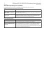
Removable Data Storage Devices (RDSDs)
For full details on RDSD operation, refer to the PACSystems CPU Reference Manual, GFK-2222R or later.
RDSD Restrictions and Open Issues in this Release
Restriction/Open Issue
Description
Default RDSD Write to Flash
value is ‘N’ when no Options.txt
file is created
The default RDSD Write_Flash value is ‘N’. Storing a project from the RDSD to the
CPE305 will result in the files not being written to user flash if no Options.txt file
is included on the RDSD device.
RDSD upload / unintended OEM
protection lock
When an OEM key is set in a controller, and the controller is unlocked, if an RDSD
upload is performed, in rare occasions OEM protection will be unintentionally
locked after the upload completes. To recover, enter OEM password to unlock
the project, then clear the user memory and flash memory.
RDSD Operational Notes
Operational Note
Description
RDSD / Programmer Interaction
When using RDSD, all Proficy Machine Edition Logic Developer PLC connections
must be in the Offline state for the RDSD to function properly.
RDSD OEM / Password Protection
of Former Uploads Incorrectly
Maintained
When deleting an OEM key from a project, you must remove the Energy Pack
and cycle power before writing to the RDSD. If this procedure is not followed
there are rare occasions where the OEM key that had been deleted may be
restored on the RDSD device and therefore could be unexpectedly downloaded
to the CPU on a subsequent RDSD download.
PACSystems RX3i CPU IC695CPE305-ACAN Important Product Information
GFK-2714P
19
November 2014
Energy Pack Operational Notes
For details on the Energy Pack, refer to the datasheet GFK-2724.
The %S0014 (PLC_BAT) system status reference indicates the Energy Pack status as follows:
0
Energy Pack is connected and functioning.
1
Note:
Energy Pack is not connected or has failed.
When the Energy Pack is powered up for the first time, or is in a system that has been powered down
long enough to completely discharge the Energy Pack, it may require a few seconds for it charge to its
operating level. The CPU’s STATUS LED will blink green during this time.
Because the Time of Day (TOD) clock is powered by the Real Time Clock battery, removal of the Energy
Pack does not cause the CPU to lose the TOD value.
Note:
Power-Up Characteristics
The Conditional Power-up From Flash feature works the same as in previous Rx3i CPUs: that is if the configuration is
configured for “Conditional – Flash” and the Energy Pack is disconnected or has failed, the contents of flash will be
loaded into RAM at power up. The CPU’s logic and configuration source and operating mode at power-up are in
accordance with the tables on pages 4-14 and 4-15 of GFK-2222, where “memory not preserved” means that the
Energy Pack is not connected or not working. The contents of those tables apply as follows:
•
All entries in the “Logic/Configuration Source and CPU Operating Mode at power-up” table which address
“Logic/Configuration Power-up Source in User Memory” apply to Logic/Configuration as if there were a battery.
•
The condition of “Memory not preserved (i.e., no battery or memory corrupted)” is created on a CPE305 by
power cycle with the Energy Pack removed.
•
The condition of “No configuration in User Memory, memory preserved” is created on a CPE305 by clearing
configuration (or never downloading configuration), and then cycling power with the Energy Pack connected.
•
The conditions for Logic/Configuration source of “Always Flash,” “Conditional Flash” and “Always RAM” are
created by setting the appropriate configuration setting in the CPE305 and cycling power with the Energy Pack
connected.
•
User memory is preserved only if the Energy Pack is connected (and charged) at power-down. Similarly, user
memory is preserved only if the Energy Pack is present at power-up.
•
The user memory is preserved on a CPE305 by an Energy Pack connection at the instant of power-down and
the instant of power-up. Removing or reconnecting the Energy Pack while the CPE305 is not powered has no
effect on the preservation of user memory.
Energy Pack Replacement
If an Energy Pack fails, you can replace it with a new unit while the CPU is in operation. When an Energy Pack is
replaced, the new Energy Pack must charge. If a loss of power occurs while the Energy Pack is disconnected or before it
is fully charged, a memory loss may occur.