1
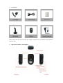
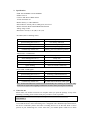
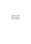
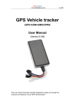
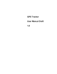
WIRELESS ALARM MONITORING
User Manual V1.2
Please read this user manual fully before attempting installation. Pictures are for indication and
illustration purposes only.
1. Accessories
Please make sure that all accessories are complete. Pictures are for indication and illustration
purposes only.
2. Appearance and keys introduction
3. Specification
GSM: 900/1800MHz or 850/1900MHz
GPRS: Class 12
Camera: 30W Pixel CMOS camera
T-card: maximum 4G
Built-in battery: 3.7vDC/800mAh
LED indicator: Armed-yellow, GSM-green, Power-red
Built-in antenna: Built-in GSM Dual-band antenna
Voltage range: 5vDC
Dimensions: 82.5(L) x 44.3(W) x 28.7 (H)
Red LED (Power/ Working status)
Status
Implication
Quick flashing(interval 0.1s)
Low battery indication
Slow flashing(interval 1s)
Normal operating
Continuously in bright state
Battery charging
Continuously in dark state
Battery power loss/Internal problem
Yellow LED(Arm/Disarm)
Status
Implication
Slow flashing(interval 1s)
Delay arm
Continuously in bright state
Arming
Continuously in dark state
Disarming
Quick flashing
Arm (10 seconds countdown)
Green LED(GSM signal)
Status
Implication
Quick flashing(interval 0.1s)
Searching (GSM Initialization)
Slow flashing(interval 1s)
GSM normally on
Continuously in bright state
GSM conversation/GPRS activation
Continuously in dark state
No SIM card installed/No GSM signal
Note: All the LED indicators would turn off automatically after working for 5 minutes. They
would turn on again when toggling Arm/Disarm switch or short pressing the On/Off key.
4. Notice for use
Please make sure all the accessories are complete when you open the package. If any of the
following is lacking, please contact with your provider as soon as possible.
Device terminal 1 Lithium battery 1 Charger 1 USB cable 1 Bracket 1
User manual 1
This device could help resolve your worries if you are often not at home. What you need to do
is to install the device in the monitoring area. Configured with a human-body infrared sensor,
the device would take pictures and video recording and save it in SD card when it senses
persons in your monitoring area. At the same time, your mobile phone could receive alarm
MMS from the device. You can also check the pictures on Internet service platform. Please
refer to the following chapters for further using method.
5. Operation manual
5.1 Installation of SIM card and SD card
Insert and remove SIM card
Turn off the device; remove battery and other external power supplies.
Insert and slide the SIM card correctly by following the arrow direction.
To remove the SIM card, please turn off the terminal; remove battery and other external
power supplies; hold the notch of SIM card and lift it slightly up to take card out.
Remark: 1. Please use SIM card with GSM network.
2. Please confirm that the SIM card has opened GPRS service.
3. Please confirm that the SIM card has opened Caller ID and MMS function.
Insert and remove SD card
Remove battery and other external power supplies.
Insert and slide the SIM card with the metal part facing down by following below arrow
direction at battery slot until SIM card is completely inserted in right position.
To remove the SD card, please turn off the device and remove external power supplies.
The SD card would pop up by slightly pressing.
Remark: when inserted and removed SIM or SD card, the device must be power off, or the
cards would be easily damaged.
Note: Please insert SD card before use. The device could not operating normally if the SD
card is removed or working.
5.2 Switch On /Off
After the battery is inserted, long press the On/Off key. It’s switched on when the red and
green indicators start flashing.
Note: If SOS number was set before, the device would send message “The system starts up”
to the SOS numbers two minutes after switching on.
5.3 Installation of the device
Fix the base with the bracket and keep the base rabbet upward.
Put the device on the base with the logo side facing forward and straightly to ensure the
photos and videos are taken in right direction. Then fix the bracket on the wall or other
solid object. (An electric outlet is available around.)
Connect power for use.
5.4 Battery Charging
Make sure the charger is connected with power.
The device could be normally used while charging. Continually bright state of the red
LED light indicates the terminal is charging. Slow flashing indicates power is enough.
Quick flashing indicates low power and charging is needed timely.
The charger could continue to supply power even when the battery is charged.
Remark: Battery charging should be operated under 0℃~40℃ with chargers provided by the
manufacturer. Any unauthorized charger may result in danger and breach of
approval and warranty terms of this device.
6 Function settings
6.1 Parameter setting
6.1.1 Add or modify SOS numbers
Only those SOS numbers set before are authorized to remotely control the device.
SOS number could be added by SMS from any mobile phone:
SOS, A, phone number 1, phone number 2, phone number 3#
“A” means adding SOS number
For example,
SOS, A, 13500000001, 13500000002, 13500000003#
Each SOS number can be set with a specific phone number, if only need to set one SOS
number, leave it blank if the corresponding SOS number is not needed.
For example,
SOS, A, 13500000001#---The first SOS number
SOS, A, ,13500000002#---The second SOS number
SOS, A, ,,13500000003#---The third SOS number
When SOS numbers setting succeed, the device would send message to the relevant
mobile phones.
Example of the message: SOS1: 13500000001
SOS2: 13500000002
SOS3: 13500000003
6.1.2 Delete SOS numbers by SMS
Delete by SMS from SOS phones:
SOS,D, number order1, number order2, number order3#
“D” means deleting SOS number
SOS,D,1#----deleting the first phone number
SOS,D,2#----deleting the second phone number
SOS,D,3#----deleting the third phone number
If you’d like to delete several numbers at one time, the message is:
SOS,D,1,3#---- deleting the first and third phone number
If you don’t remember the phone number order, the message could be:
SOS,D, phone number#---- deleting the phone number for SOS
For example:
SOS,D, 13527852360#---- deleting the phone number, 13527852360, for SOS
When SOS numbers are deleted successfully, the device would send message to the
relevant mobile phones.
Example of the message reply: SOS1: 13500000001
SOS2:
SOS3: 13500000003
The second phone number, SOS2, is deleted.
6.1.3
Add/Delete SOS numbers by service platform
Besides SMS, service platform is also available to add/delete SOS numbers. You can log
on the service platform provided by distributors or service providers to set SOS numbers.
6.1.4
Language setting
Send SMS to the device from the SOS phone: LANG,L#
Set “L” as 1, the setting language will be English; set “L” as 0, the setting language will
be Chinese.
Message reply when setting is completed:
a) Message reply when the language is set as English: The current language is English.
b) Message reply when the language is set as Chinese: 语言设置成功!
6.1.5
APN settings
Send SMS command to the device from the SOS phone to set device APN:
a) APN, network name#
For example: APN, cmnet#
b) APN, network name, user name, user account#
For example: APN, cmnet, user, 123456#
When setting succeeds, SMS is replied as “OK”
6.1.6
Sever command setting
Send SMS command to the device from the SOS phone in the following two ways:
a) DNS: SERVER, mode 1, domain name, port, 0#
For example: SERVER, 1, www.ydpat.com, 8011, 0#
b) IP: SERVER, module0, IP, port, 0#
For example: SERVER, 0, 211.154.135.113.8011,0#
Note: Currently only TCP protocol is supported. UDP protocol is not supported.
6.1.7
MMS setting
Send SMS command to the device from the SOS phone in the following two ways:
a) MMS, MMS center address, IP, port, Access point name(APN), user name, user
account, type of connection#(0 means HTTP, 1means WAP)
For example: MMS, http://kks.com,211.154.135.113.8011.cmwap,yang,3333,1#
b) MMS, MMS center address, IP, Port, Access point name (APN)#
For example: MMS, http://kks.com,211.154.135.113.8011.cmwap#
Devices will automatic restart after setting
6.1.8
Query parameter setting
Query the current GPRS and MMS parameters
Send SMS command, GPRSSET#, to the device from the SOS phone:
Example of the message replied:
GPRS APN: cmnet
GPRS name:
GPRS pwd:
MMS URL:
MMS IP: 211.154.135.113
MMS port: 8011
MMA APN: cmwap
MMS name:
MMS pwd:
MMS type:
SERVICE SET:
url: www.ydpat.com
mod:
addr:
port:
protol_type:
6.2 Arm/Disarm
6.2.1
Arm/Disarm by toggling the switch
Toggle the Arm/Disarm switch:
If the device is in disarm status, toggle the ARM switch once to enter delay arming status
with the yellow LED indicator flashing. After 5 minutes it enter arming status with the
yellow LED indicator continually lighting.
If the device is in arm status, toggle the ARM switch once to enter disarming status with
the yellow LED indicator off.
6.2.2
Arm/Disarm by SMS
Arm by SMS
Send SMS command: “On#” to the device from the SOS phone:
If arm setting succeeds or it’s in arming status, SMS is replied as: “Arm setting success!”
Disarm by SMS
Send SMS command: “OFF#” to the device from the SOS phone:
If disarm setting succeeds or it’s in disarming status, SMS is replied as: “Disarm setting
success!”
6.2.3
Arm/Disarm by dialing
When the device is in disarming status, dial the device number from SOS phone and hang
up in 10 seconds. When receiving the call, the device would enter arming status
automatically and reply SMS “Remote arm setting success!”, if the SOS phone doesn’t
not hang up in 10 seconds, the device would enter voice monitoring status.
When the device is in arming status, dial the device number from SOS phone and hang up
in 10 seconds. When receiving the call, the device would enter disarming status
automatically and reply SMS “Remote disarm setting success!”, if the SOS phone doesn’t
not hang up in 10 seconds, the alarm would enter voice monitoring status.
6.2.4
Arm/Disarm by service platform
Log in the service platform via IMEI number or account. Click the “Arm”/”Disarm” icon
on the upper-right side of the page. The device would instantly start “Arm”/”Disarm”
operation when it receives command.
Note: When log on the service platform via IMEI number in the first time, the system
would automatically allot an account for log on use later.
6.2.5
Timing Arm/Disarm
If you don’t need to monitor for 24 hours, you could send SMS command to the device
from the SOS phone to set arming time period:
SMS command for opening timing arm: Time on#
SMS command for closing timing arm: Time off#
SMS command for setting time period:
TIME, PERIOD1, PERIOD2, PERIOD3#
Format of Time period: HH:MM-HH:MM;
Example of SMS command:
TIME, 00:00-08:00#---set the first time period
TIME, 00:00-08:00, 12:00-13:00#---set the first and second time period
00:00-00:00 means null time period.
When setting succeeds, the SMS would reply contents including arming status, timing
arm status, arming time period, current time and SOS number.
Note: 1. The device would synchronize time once each day automatically with the server
via GPRS, thus manually setting time is not needed.
2. When entering arming time period, the device would automatically enter arming
status from disarming status before.
6.3
Check device settings by SMS:
The preset SOS numbers can send SMS command: “SET#” to the device to check the
settings of it.
The replied message format as below:
SOS1: 13500000001----The first SOS number is set.
SOS2: 13500000002----The second SOS number is set.
SOS3: 13500000003----The third SOS number is set.
Timing arm status: close/open
Arming time period: 00:00-08:00, 12:00-13:00, 18:00-20:00---Arming time periods are
set.
Current time is: 2011-6-1; 16:57:29---current time
IMEI is: xxxxxxxxxxxxxxxx---IMEI number of the device
Account:xxxxxx----user account of the platform
MMS alarm: On/Off---MMS alarm status
Picture resolution: 320x240 or 640x480
6.4 MMS alarm On/Off
MMS alarm On: Send SMS command: “MMSON#” to the device from the SOS phone. When
MMS alarm is On, the device would reply SMS of the MMS alarm status.
Example of the SMS: MMS alarm: On
MMS alarm Off: Send SMS command: “MMSOFF#” to the device from the SOS phone.
When MMS alarm is Off, the device would reply SMS of the MMS alarm status.
Example of the SMS: MMS alarm: Off
6.5 Photos taking
6.5.1 Via SMS
Send SMS command, “PHOTO#” or “333” to the device from the SOS phone. If the
device is on, it would take photos and send MMS of these photos to the above SOS
phone.
6.5.2
Via service platform
Log on the service platform and click the icon “ Take photos” on the upper-right side of
the page. If the device is on, it would take photos and send these pictures to the platform.
Note: 1. All letters and characters of SMS command should be input in English. No blank
space is permitted and the format should be completed.
2. No case sensitive.
3. Only preset SOS numbers can make remote arming, disarming and tacking
photos.
6.6 Infrared alarm
Under arming status, when the infrared sensor detects human-body: the device would take a
set of photos. The first photo would be sent to the specific SOS number via MMS with
message content “Emergency alarm”, and the device would record a one-minute video
automatically and sent the video and a set of pictures to the platform.
Both the photos and video would be saved in the corresponding catalogue PHOTO and
VIDEO in SD card. If the storage capacity is not enough, the device would automatically
delete the earliest photos and videos. Users may check the photos and videos on the computer
by connecting device with USB cable.
6.7 Power cut-off alarm
When the electricity supply is cut off, the device would send SMS: “Attention please!
Power is cut off!” to the SOS numbers. At the meantime, the device will upload power
cut off alarm data and time to the server via GPRS.
6.8 Low battery alarm
When the device is detected with low battery, it would send alarm SMS “Attention!
Battery too low, please charge.” to the SOS numbers. At the meantime, the device will
upload low battery alarm data and time to the server via GPRS.
6.9 Power off alarm
When the battery is too low to support operation, the device would send alarm SMS “The
system is power off”, which inform user of charging it timely and turn off subsequently.
6.10 SD card failure alarm
When the SD card is not inserted or the inserted way is not right, the device would send
alarm SMS “SD card detection failure, please make sure that whether the card is inserted or
storage space is enough” to the SOS numbers. When received this SMS, please insert the SD
card again in the right way.
6.11 Check photos and videos in SD card
Take off the device and charger, turn it off and connect it with a computer via USB cable.
Photos in the catalogue “PHOTO” and videos in the catalogue “VIDEO” to view, copy or
delete.
6.12 Voice monitoring
When the specific SOS phone dials the device, ringing for 10 seconds, it will enter voice
monitoring status. At this time, caller can monitor the sound in the area.
Note: 1. The SIM card put into the device should be equipped with caller identification.
2. To realize this function, please set special numbers beforehand.
3. If infrared alarm is activated during monitoring, monitoring function would be
interrupted for emergency alarm.
6.13 Service platform
User could log in service platform: http://www.cootrack.com to make arming, disarming,
taking pictures function.
6.13.3 Check information
Instantly uploaded alarm photos could be checked in the alarm photo column on the home
page. Instantly uploaded power cut off alarm data and low battery information could be
checked in the abnormal device column.
The relevant account, IMEI number, device status online or not, arming status could be
checked on the home page.
6.13.4 Reset
User with SOS number phone can send “RESET#” to the device, which would reply “The
system would restart in 30 seconds”. This command is used when the device is operating
abnormally.
6.13.5 Restore to factory setting
User with SOS number phone can send “FACTORY#” to the device, which would reply “It
succeeds. The system would restart in 30 seconds”. This command is used when the device is
operating abnormally due to parameter change.
6.13.6 Set photo resolution
User with SOS number phone can send “SIZE,0#” or “SIZE,1#” to the device to set camera
resolution. “1” means the camera resolution is 640x480; “0” means the camera resolution is
320x240.
Note: 1. With 640x480 resolutions, the camera would take only two pictures when infrared
alarm is activated. The uploading time is relatively slow.
2. With 320x240 resolutions, the camera would take three pictures when infrared alarm
is activated.
7 Appendix
7.1 Battery safety
Please use the battery provided by the manufacturer of the device. Any use of other
accessories would lead to void warranty service. The terminal manufacturer is not liable
for any damage resulted from using accessories from other channels.
New battery should be fully charged (12 hours) and discharged for two or three times to
achieve the best performance.
Battery can be charged and discharged for hundreds of times and finally get useless.
When calling time and standby time is decreased obviously, you need to change new
battery.
Touching any metal object (key in pocket) would easily cause battery short-circuit.
Do not forcibly bend and open battery.
Keep the battery away from water and fire.
Battery should be charged at room temperature. If temperature is lower than 0℃ or
higher than 45℃, the battery may not be charged
7.2 Trouble shooting
If there is trouble during using the device, please read the solution as follow or contact provider.
Common
problems
Causes
Solution
Fail to switch on
Power off
Charge battery
The called number is not the SOS
number
Set up SOS number
SIM card without caller ID display
function
Active function of caller ID display
Fail to monitor
Fail to connect
network
Fail to
charge
Bad installation of SIM card
check SIM card installation
Filth on the SIM card iron
surface.
Clean it
useless SIM
contact internet operator
Beyond GSM service area
Use it in effective GSM service
offer area
bad signal
Try again in a better signal area
The voltage is unsuitable
Connect with power with suitable
voltage
Bad connection
Check connection with charger