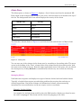
1
NETCONDUCTOR USER’S
MANUAL
Release 2.2
299-434-405
First Edition (January 2007)
This edition applies to the Nuera Communications, Inc. NetConductor. The licensed product described in this document and all licensed materials that are available for it are provided by Nuera under terms of the agreement for
Nuera licensed products. Nuera periodically makes additions, deletions, or changes to the information in this document. Before you use this document, consult Nuera or your distributor for the most recent Nuera edition.
The author and publisher have made reasonable efforts to ensure the accuracy and timeliness of the information in
this book. However, neither the author nor the publisher shall have any liability with respect to loss or damage
caused or alleged to be caused by reliance on any information in this book.
Nuera may have patents or pending patent applications covering material in this document. Furnishing this document does not of itself constitute a grant of any license or immunity under any patents, patent applications, trademarks, copyrights, or other rights of Nuera, or of any third party, or any right to refer to Nuera in any advertising or
other marketing activities. Nuera assumes no responsibility for any infringement of patents or other rights of third
parties that may result from use of the material in this document or for the manufacture, use, lease, or sale of
machines or software programs described herein, outside of any responsibilities assumed in the original or subsequent purchase or lease agreements.
This document may contain information about, or make reference to, Nuera products, programming, or services that
are not available in your country. This information must not be construed to mean that Nuera intends to make available such products, programs, or services in your country.
A form for your comments is provided at the back of this document. If the form has been removed, address your comments to: Nuera Communications, Inc., Professional Services, 10445 Pacific Center Court, San Diego, CA 92121.
Nuera may use or distribute any of the information you supply in any way it believes appropriate without incurring
any obligation to you.
No part of this publication may be reproduced in any manner without the written permission of Nuera, Inc. For information, write to: Nuera Communications, Inc., Legal Office, 10445 Pacific Center Court, CA 92121.
© 2007 by Nuera Communications, Inc.
All rights reserved
2
Warranty
Nuera's standard warranty is one year from the date of shipment and is verified by serial number of the
system. Any defective component will be replaced or repaired at no charge during this period. If any equipment fails within the first 90 days of shipment, an advance replacement will be sent or on-site repair performed at Nuera's discretion, at no charge. After that period, and for the reminder of the warranty,
defective modules will be repaired at Nuera and then returned to the customer.
Once the warranty has expired, the components can either be returned to Nuera for repair, or an advance
replacement can be provided. The repair and advance replacement pricing are described in the Nuera Global Pricelist.
In order to exercise your rights to repair under this warranty, you must first contact Nuera to obtain a
repair authorization (RA) number. If you must return the unit to Nuera for repair while the unit is under
warranty, Nuera will pay the cost of shipping it to and from Nuera.
Software License Agreement
Each software Product, including any documentation relating to or describing such Software, provided by
Nuera (hereinafter collectively called “Software”) is furnished to you under a nonexclusive,
nontransferable license solely for your own use only on the single processor on which the Software is first
installed. The Software may not be copied, in whole or in part, except for archival purposes, to replace a
defective copy, or for program error verification.
You may not reverse engineer, decompile, or disassemble the Software, except to the extent such foregoing
restriction is expressly prohibited by applicable law.
The term of each paid-up license shall expire at such time as you discontinue use of the applicable
Software on the single processor specified above but otherwise shall be without restriction as to time.
The Software (including any images, applets, photographs, animations, video, audio, music, and text
incorporated into the Software) is owned by Nuera or its suppliers and is protected by United States
copyright laws and international treaty provisions. Therefore, you must treat the Software like any other
copyrighted material (for example, a book or musical recording) except that you may either (a) make one
copy of the Software solely for backup or archival purposes, or (b) transfer the Software to a single hard
disk provided you keep the original solely for backup or archival purposes. You may not copy the printed
materials accompanying the Software.
3
ORCA User Library
All books that support the ORCA product line are provided on a compact disc (CD) in Adobe Acrobat format. Included on the CD is the appropriate version of Adobe Acrobat Reader.
This section lists the titles of all the books in the ORCA library. To order any of these books, contact your
distributor or Nuera directly. To make comments or suggestions regarding any of these books, direct your
correspondence to [email protected].
Number
Book
299-225-4nn
ORCA SSC Softswitch User’s Guide
This book presents conceptual information about the use and functionality of the ORCA
SSC Softswitch. It also provides information about installing and configuring SSC for use
with other equipment.
299-193-5nn
ORCA GX-Series Software Manual
This book is designed for the system integrator/system administrator who needs to configure ORCA GX gateways at an end-user site. Its purpose is to guide this individual through
the configuration steps required to get the ORCA GX gateway correctly configured using
network management software.
299-297-5nn
ORCA RDT-8g Software Manual
This book is designed for the system integrator/system administrator who needs to configure ORCA RDT-8g gateways at an end-user site. Its purpose is to guide this individual
through the configuration steps required to get the ORCA RDT-8g gateway correctly configured using network management software.
299-298-5nn
ORCA RDT-8v Software Manual
This book is designed for the system integrator/system administrator who needs to configure ORCA RDT-8v gateways at an end-user site. Its purpose is to guide this individual
through the configuration steps required to get the ORCA RDT-8v gateway correctly configured using network management software.
299-252-5nn
ORCA BTX-Series Software Manual
This book is designed for the system integrator/system administrator who needs to configure ORCA BTX gateways at an end-user site. Its purpose is to guide this individual through
the configuration steps required to get the ORCA BTX gateway correctly configured using
network management software.
299-335-1nn
ORCA Gateway Hardware Manual
This book presents conceptual information about the use, functionality, and specifications
of the ORCA 21-slot and 8-slot gateways, including installation steps and information.
299-433-1nn
ORCA-4K Hardware Manual
This book presents conceptual information about the use, functionality, and specifications
of the ORCA 4K gateway, including installation steps and information.
4
Number
Book
299-432-5nn
ORCA BTX-4K Application Manual
This book is designed for the system integrator/system administrator who needs to configure ORCA BTX-4K gateways at an end-user site. Its purpose is to guide this individual
through the configuration steps required to get the ORCA BTX-4K gateway correctly configured using network management software.
299-434-4nn
NetConductor User’s Guide
This book presents conceptual information about the use, functionality, and specifications
of the NetConductor application, including installation steps and information.
Additional ORCA books are available in PDF format from Nuera’s website,
http://www.nuera.com. For information regarding pricing and availability, contact a sales representative
at:
Nuera Communications, Inc.
10445 Pacific Center Court
San Diego, CA 92121
858-625-2400
Trademarks Used in This Manual
The following list contains trademarks that are used in this manual. In the United States, these trademarks are registered trademarks; in World Trade countries, these trademarks are not registered.
Trademark
Trademark Owner
ANSI
American National Standards Institute
Cisco
Cisco Systems, Inc.
IBM
International Business Machines, Inc.
Microsoft
Microsoft Corporation, Inc.
ORCA
Nuera Communications, Inc.
UNIX
The Open Group
VT100
Compaq Digital Equipment Corporation
Windows XP
Microsoft Corporation, Inc.
5
6
Trademark
Trademark Owner
Red Hat Linux
Red Hat
MySQL
MySQL AB
TABLE OF CONTENTS
About This Book . . . . . . . . . . . . . . . . . . . . . . . . . . . . . . . . . . . . . . . . . . . . . . . . . . . . . . 13
Who Should Use This Book . . . . . . . . . . . . . . . . . . . . . . . . . . . . . . . . . . . . . . . 13
Conventions Used in This Book . . . . . . . . . . . . . . . . . . . . . . . . . . . . . . . . . . . . 13
Notes, Cautions, and Warnings . . . . . . . . . . . . . . . . . . . . . . . . . . . . . . 13
How Numbers Are Used . . . . . . . . . . . . . . . . . . . . . . . . . . . . . . . . . . . . 14
Replaceable Input Values. . . . . . . . . . . . . . . . . . . . . . . . . . . . . . . . . . . 14
Getting Help . . . . . . . . . . . . . . . . . . . . . . . . . . . . . . . . . . . . . . . . . . . . . . . . . . . 15
Checklist . . . . . . . . . . . . . . . . . . . . . . . . . . . . . . . . . . . . . . . . . . . . . . . . 15
Contacts. . . . . . . . . . . . . . . . . . . . . . . . . . . . . . . . . . . . . . . . . . . . . . . . . 16
Chapter 1. Introduction . . . . . . . . . . . . . . . . . . . . . . . . . . . . . . . . . . . . . . . . . . . . . . . . 17
The Server. . . . . . . . . . . . . . . . . . . . . . . . . . . . . . . . . . . . . . . . . . . . . . . . . . . . . 18
The Client . . . . . . . . . . . . . . . . . . . . . . . . . . . . . . . . . . . . . . . . . . . . . . . . . . . . . 19
Chapter 2. Installation & Upgrades . . . . . . . . . . . . . . . . . . . . . . . . . . . . . . . . . . . . . . 21
Network Requirements . . . . . . . . . . . . . . . . . . . . . . . . . . . . . . . . . . . . . . . . . . 21
Server Prerequisites . . . . . . . . . . . . . . . . . . . . . . . . . . . . . . . . . . . . . . . . . . . . . 21
Hardware. . . . . . . . . . . . . . . . . . . . . . . . . . . . . . . . . . . . . . . . . . . . . . . . 22
Software. . . . . . . . . . . . . . . . . . . . . . . . . . . . . . . . . . . . . . . . . . . . . . . . . 22
Installing MySQL . . . . . . . . . . . . . . . . . . . . . . . . . . . . . . . . . . . . . . . . . . . . . . . 23
Installing and Upgrading NetConductor . . . . . . . . . . . . . . . . . . . . . . . . . . . . 24
Installing NetConductor. . . . . . . . . . . . . . . . . . . . . . . . . . . . . . . . . . . . 24
Upgrading NetConductor . . . . . . . . . . . . . . . . . . . . . . . . . . . . . . . . . . . 24
Upgrading Management Keys . . . . . . . . . . . . . . . . . . . . . . . . . . . . . . . 25
Enabling HTTP over SSL (HTTPS) . . . . . . . . . . . . . . . . . . . . . . . . . . . . . . . . . 26
Enabling Secure Firmware Download (BTX-4K) . . . . . . . . . . . . . . . . . . . . . . 29
Configuring SNMP Version . . . . . . . . . . . . . . . . . . . . . . . . . . . . . . . . . . . . . . . 31
Defining NetConductor SNMP Version (per NE) . . . . . . . . . . . . . . . . 31
Defining SNMP Version for an NE . . . . . . . . . . . . . . . . . . . . . . . . . . . 31
Authentication Services . . . . . . . . . . . . . . . . . . . . . . . . . . . . . . . . . . . . . . . . . . 32
Authentication Services and NetConductor . . . . . . . . . . . . . . . . . . . . 32
Installing a High Availability (HA) Server . . . . . . . . . . . . . . . . . . . . . . . . . . . 33
Prerequisites . . . . . . . . . . . . . . . . . . . . . . . . . . . . . . . . . . . . . . . . . . . . . 33
Server Preparation . . . . . . . . . . . . . . . . . . . . . . . . . . . . . . . . . . . . . . . . 34
Heartbeat Installation . . . . . . . . . . . . . . . . . . . . . . . . . . . . . . . . . . . . . 36
Heatbeat Configuration . . . . . . . . . . . . . . . . . . . . . . . . . . . . . . . . . . . . 36
NetConductor User’s Manual
7
Starting and Checking the Heartbeat . . . . . . . . . . . . . . . . . . . . . . . .
Replicate the MySQL Database . . . . . . . . . . . . . . . . . . . . . . . . . . . . .
Set Up NetConductor Monitoring . . . . . . . . . . . . . . . . . . . . . . . . . . . .
Setup MySQL Monitoring . . . . . . . . . . . . . . . . . . . . . . . . . . . . . . . . . .
Changing MySQL Passwords . . . . . . . . . . . . . . . . . . . . . . . . . . . . . . . . . . . . .
Installing the Craft Interface . . . . . . . . . . . . . . . . . . . . . . . . . . . . . . . . . . . . .
38
39
42
42
43
44
Chapter 3. NetConductor Basics. . . . . . . . . . . . . . . . . . . . . . . . . . . . . . . . . . . . . . . . .
Accessing NetConductor . . . . . . . . . . . . . . . . . . . . . . . . . . . . . . . . . . . . . . . . .
Via the NetConductor Server . . . . . . . . . . . . . . . . . . . . . . . . . . . . . . .
Via the NetConductor Craft Interface . . . . . . . . . . . . . . . . . . . . . . . .
Login . . . . . . . . . . . . . . . . . . . . . . . . . . . . . . . . . . . . . . . . . . . . . . . . . . .
The User Interface . . . . . . . . . . . . . . . . . . . . . . . . . . . . . . . . . . . . . . . . . . . . . .
Links Pane . . . . . . . . . . . . . . . . . . . . . . . . . . . . . . . . . . . . . . . . . . . . . .
Navigation Pane. . . . . . . . . . . . . . . . . . . . . . . . . . . . . . . . . . . . . . . . . .
Information Pane . . . . . . . . . . . . . . . . . . . . . . . . . . . . . . . . . . . . . . . . .
Alarm Pane. . . . . . . . . . . . . . . . . . . . . . . . . . . . . . . . . . . . . . . . . . . . . .
Dual NIC Installation (Optional) . . . . . . . . . . . . . . . . . . . . . . . . . . . . . . . . . .
47
47
47
49
49
50
50
51
51
53
54
Chapter 4. Using NetConductor . . . . . . . . . . . . . . . . . . . . . . . . . . . . . . . . . . . . . . . . .
Using Links - Inventory. . . . . . . . . . . . . . . . . . . . . . . . . . . . . . . . . . . . . . . . . .
Using the Hierarchy. . . . . . . . . . . . . . . . . . . . . . . . . . . . . . . . . . . . . . .
Creating a Network Element . . . . . . . . . . . . . . . . . . . . . . . . . . . . . . .
Using Links - Security . . . . . . . . . . . . . . . . . . . . . . . . . . . . . . . . . . . . . . . . . . .
Roles . . . . . . . . . . . . . . . . . . . . . . . . . . . . . . . . . . . . . . . . . . . . . . . . . . .
Users . . . . . . . . . . . . . . . . . . . . . . . . . . . . . . . . . . . . . . . . . . . . . . . . . . .
Session . . . . . . . . . . . . . . . . . . . . . . . . . . . . . . . . . . . . . . . . . . . . . . . . .
Using Links - Advanced. . . . . . . . . . . . . . . . . . . . . . . . . . . . . . . . . . . . . . . . . .
Shutdown the Server . . . . . . . . . . . . . . . . . . . . . . . . . . . . . . . . . . . . . .
Viewing Logs . . . . . . . . . . . . . . . . . . . . . . . . . . . . . . . . . . . . . . . . . . . .
Using Links - Backup Restore. . . . . . . . . . . . . . . . . . . . . . . . . . . . . . . . . . . . .
Using Links - Tasks . . . . . . . . . . . . . . . . . . . . . . . . . . . . . . . . . . . . . . . . . . . . .
Server License . . . . . . . . . . . . . . . . . . . . . . . . . . . . . . . . . . . . . . . . . . .
Import XML . . . . . . . . . . . . . . . . . . . . . . . . . . . . . . . . . . . . . . . . . . . . .
Update Firmware . . . . . . . . . . . . . . . . . . . . . . . . . . . . . . . . . . . . . . . . .
NE Licenses . . . . . . . . . . . . . . . . . . . . . . . . . . . . . . . . . . . . . . . . . . . . .
Using Links - Performance . . . . . . . . . . . . . . . . . . . . . . . . . . . . . . . . . . . . . . .
Creating a New Schedule . . . . . . . . . . . . . . . . . . . . . . . . . . . . . . . . . .
Creating a New Filter for Your Schedule . . . . . . . . . . . . . . . . . . . . . .
55
55
55
56
58
58
61
62
63
63
63
66
67
67
67
68
68
70
71
71
Chapter 5. Troubleshooting. . . . . . . . . . . . . . . . . . . . . . . . . . . . . . . . . . . . . . . . . . . . .
Setup and Configuration . . . . . . . . . . . . . . . . . . . . . . . . . . . . . . . . . . . . . . . . .
Licensing Problems . . . . . . . . . . . . . . . . . . . . . . . . . . . . . . . . . . . . . . .
Startup Problems . . . . . . . . . . . . . . . . . . . . . . . . . . . . . . . . . . . . . . . . .
73
73
73
73
Chapter 6. Periodic Maintenance . . . . . . . . . . . . . . . . . . . . . . . . . . . . . . . . . . . . . . . . 77
Chapter 7. Alarm Forwarding. . . . . . . . . . . . . . . . . . . . . . . . . . . . . . . . . . . . . . . . . . . 79
Introduction . . . . . . . . . . . . . . . . . . . . . . . . . . . . . . . . . . . . . . . . . . . . . . . . . . . 79
Configuring Alarm Forwarding . . . . . . . . . . . . . . . . . . . . . . . . . . . . . . . . . . . 79
NetConductor User’s Manual
8
Active Alarm Report . . . . . . . . . . . . . . . . . . . . . . . . . . . . . . . . . . . . . . . . . . . .
Alarm XML Syntax . . . . . . . . . . . . . . . . . . . . . . . . . . . . . . . . . . . . . . . . . . . . .
XML Content . . . . . . . . . . . . . . . . . . . . . . . . . . . . . . . . . . . . . . . . . . . .
Basic Structure. . . . . . . . . . . . . . . . . . . . . . . . . . . . . . . . . . . . . . . . . . .
Examples and their NetConductor Alarm Equivalents . . . . . . . . . . .
List of RDT-8v Alarms. . . . . . . . . . . . . . . . . . . . . . . . . . . . . . . . . . . . . . . . . . .
81
83
83
83
84
85
Bibliography. . . . . . . . . . . . . . . . . . . . . . . . . . . . . . . . . . . . . . . . . . . . . . . . . . . . . . . . . 95
MicroMuse, Inc. . . . . . . . . . . . . . . . . . . . . . . . . . . . . . . . . . . . . . . . . . . . . . . . . 95
9
10
LIST OF FIGURES
Figure 1. Geographically-Distributed Network Elements . . . . . . . . . . . . . . . . . . . . . 17
Figure 2. Simple Network Layout . . . . . . . . . . . . . . . . . . . . . . . . . . . . . . . . . . . . . . . . 19
Figure 3. Server License Screen . . . . . . . . . . . . . . . . . . . . . . . . . . . . . . . . . . . . . . . . . 26
Figure 4. Create New NE, Step 1 . . . . . . . . . . . . . . . . . . . . . . . . . . . . . . . . . . . . . . . . 31
Figure 5. NetConductor HA Block Diagram . . . . . . . . . . . . . . . . . . . . . . . . . . . . . . . . 34
Figure 6. HTTPS Security Alert . . . . . . . . . . . . . . . . . . . . . . . . . . . . . . . . . . . . . . . . . 48
Figure 7. HTTPS Security Messages. . . . . . . . . . . . . . . . . . . . . . . . . . . . . . . . . . . . . . 48
Figure 8. Configuring IE to Disable Security Alerts . . . . . . . . . . . . . . . . . . . . . . . . . 49
Figure 9. NetConductor Login window . . . . . . . . . . . . . . . . . . . . . . . . . . . . . . . . . . . . 49
Figure 10. The NetConductor Interface . . . . . . . . . . . . . . . . . . . . . . . . . . . . . . . . . . . 50
Figure 11. Navigation pane . . . . . . . . . . . . . . . . . . . . . . . . . . . . . . . . . . . . . . . . . . . . . 51
Figure 12. Information pane . . . . . . . . . . . . . . . . . . . . . . . . . . . . . . . . . . . . . . . . . . . . 52
Figure 13. Edit Window for VPM-1 . . . . . . . . . . . . . . . . . . . . . . . . . . . . . . . . . . . . . . . 52
Figure 14. Alarm pane . . . . . . . . . . . . . . . . . . . . . . . . . . . . . . . . . . . . . . . . . . . . . . . . . 53
Figure 15. Dual NIC Installation . . . . . . . . . . . . . . . . . . . . . . . . . . . . . . . . . . . . . . . . 54
Figure 16. NetConductor Links . . . . . . . . . . . . . . . . . . . . . . . . . . . . . . . . . . . . . . . . . . 55
Figure 17. List of Network Elements . . . . . . . . . . . . . . . . . . . . . . . . . . . . . . . . . . . . . 55
Figure 18. Expanded Hierarchy - Hardware . . . . . . . . . . . . . . . . . . . . . . . . . . . . . . . 56
Figure 19. Create New NE, Step 1 . . . . . . . . . . . . . . . . . . . . . . . . . . . . . . . . . . . . . . . 57
Figure 20. Security Hierarchy . . . . . . . . . . . . . . . . . . . . . . . . . . . . . . . . . . . . . . . . . . . 58
Figure 21. Roles Table . . . . . . . . . . . . . . . . . . . . . . . . . . . . . . . . . . . . . . . . . . . . . . . . . 58
Figure 22. Role Permission Table . . . . . . . . . . . . . . . . . . . . . . . . . . . . . . . . . . . . . . . . 59
Figure 23. Create New Role . . . . . . . . . . . . . . . . . . . . . . . . . . . . . . . . . . . . . . . . . . . . . 59
Figure 24. Assigning Permissions . . . . . . . . . . . . . . . . . . . . . . . . . . . . . . . . . . . . . . . . 60
Figure 25. Users Table . . . . . . . . . . . . . . . . . . . . . . . . . . . . . . . . . . . . . . . . . . . . . . . . . 61
Figure 26. Create New User window . . . . . . . . . . . . . . . . . . . . . . . . . . . . . . . . . . . . . 62
Figure 27. Session screen. . . . . . . . . . . . . . . . . . . . . . . . . . . . . . . . . . . . . . . . . . . . . . . 63
Figure 28. Advanced Link Information pane . . . . . . . . . . . . . . . . . . . . . . . . . . . . . . . 63
Figure 29. Viewing Entry Details . . . . . . . . . . . . . . . . . . . . . . . . . . . . . . . . . . . . . . . . 64
Figure 30. Fault Log. . . . . . . . . . . . . . . . . . . . . . . . . . . . . . . . . . . . . . . . . . . . . . . . . . . 64
Figure 31. NE Event Log . . . . . . . . . . . . . . . . . . . . . . . . . . . . . . . . . . . . . . . . . . . . . . . 65
Figure 32. NE Request Log . . . . . . . . . . . . . . . . . . . . . . . . . . . . . . . . . . . . . . . . . . . . . 65
Figure 33. Server Log. . . . . . . . . . . . . . . . . . . . . . . . . . . . . . . . . . . . . . . . . . . . . . . . . . 66
Figure 34. Backup Restore Information pane. . . . . . . . . . . . . . . . . . . . . . . . . . . . . . . 66
Figure 35. Reports Navigation Pane . . . . . . . . . . . . . . . . . . . . . . . . . . . . . . . . . . . . . . 67
Figure 36. Server License Screen . . . . . . . . . . . . . . . . . . . . . . . . . . . . . . . . . . . . . . . . 67
NetConductor User’s Manual
11
Figure 37. Import XML Screen . . . . . . . . . . . . . . . . . . . . . . . . . . . . . . . . . . . . . . . . . . 68
Figure 38. Update Firmware Screen. . . . . . . . . . . . . . . . . . . . . . . . . . . . . . . . . . . . . . 68
Figure 39. Hardware (BTX-4K Shown). . . . . . . . . . . . . . . . . . . . . . . . . . . . . . . . . . . . 69
Figure 40. License Report . . . . . . . . . . . . . . . . . . . . . . . . . . . . . . . . . . . . . . . . . . . . . . 69
Figure 41. License Report . . . . . . . . . . . . . . . . . . . . . . . . . . . . . . . . . . . . . . . . . . . . . . 70
Figure 42. Performance Schedules Table . . . . . . . . . . . . . . . . . . . . . . . . . . . . . . . . . . 70
Figure 43. Create New Performance Schedule. . . . . . . . . . . . . . . . . . . . . . . . . . . . . . 71
Figure 44. Select Schedule for New Filter . . . . . . . . . . . . . . . . . . . . . . . . . . . . . . . . . 71
Figure 45. Create New Filter . . . . . . . . . . . . . . . . . . . . . . . . . . . . . . . . . . . . . . . . . . . 72
Figure 46. Alarm Forwarding Diagram (your drawing shows SNMP2c only???). . . 79
Figure 47. Active Alarm Report . . . . . . . . . . . . . . . . . . . . . . . . . . . . . . . . . . . . . . . . . 81
Figure 48. NetConductor Specific Alarm (Client View) . . . . . . . . . . . . . . . . . . . . . . . 84
Figure 49. Network Element Specific Alarm (Client View). . . . . . . . . . . . . . . . . . . . 85
12
ABOUT THIS BOOK
This book presents information on the system design and operation of the NetConductor
software. The purpose of this information is to help you install, use, and maintain the
NetConductor software in order to manage one or more Nuera ORCA gateways.
WHO SHOULD USE THIS BOOK
This book is for product distributors, systems integrators, systems analysts, and network
administrators who design, install, configure, and maintain wide area networks (WANs) and
large-scale communications applications. It contains conceptual and practical information about
how to use the NetConductor software to manage the Nuera ORCA gateways within your
network.
CONVENTIONS USED IN THIS BOOK
This book uses specific conventions to show the following types of information:
•
Number usage
•
Replaceable input values
•
Messages
Read the following sections to learn more about how this information is shown in the rest of the
book.
Notes, Cautions, and Warnings
Notes show useful information and/or contain information
requiring attention.
Cautions show information requiring extra attention.
NetConductor User’s Manual
13
Warnings are information that, if not followed, could result
in injury or equipment damage.
How Numbers Are Used
When numbers are shown in this book, they can appear as descriptive values or as data to be
manipulated internally. Decimal values are used frequently; however, alternate number bases
are useful when internal data is shown.
Large Decimal Numbers
Numbers greater than 9999 display in SI metric style, where whole numbers that contain more
than four digits are broken into groups of three digits that are separated by spaces. For example,
the number sixteen thousand three hundred eighty three is shown as 16 383. This avoids
confusion between American and European punctuation conventions. However, a number that is
internally manipulated by a computer is shown without punctuation or spaces. For example,
notice how the value 65 535 appears in the following instruction without a space or a thousands
separator within the number:
Specify 65535 as a maximum value
Numbers with Different Bases
All numbers shown in this book are decimal values unless the number base is binary or
hexadecimal. In these cases, an identifier precedes a binary or hexadecimal number. For
example:
•
the value of binary 1010
•
the value of hex 4F
Replaceable Input Values
In some cases, you can insert user-defined values into commands or you can specify local paths
and filenames. These variable values are shown in italic typeface.
For example, you might be asked to specify the name of your server in this path:
A:\LOGIN\LOGIN servername
The italic typeface shows that you need to replace servername with your local server name.
NetConductor User’s Manual
14
When you are prompted for variable input that is represented by lower-case letters, follow these
conventions:
When You See This Substitute This Value
b
Any binary digit
h
Any hexadecimal digit
n
Any decimal digit
x
Any alphabetic value, such as:
x:\DOS
where you substitute the correct drive letter
for x
Multiple letters
A series of digits, such as:
FIRST 2 HEX BYTES: hhhh
where you substitute four hexadecimal
digits for hhhh
When you are prompted for variable input with embedded decimal points, replace the variable
digits and let the decimal points remain to separate 32-bit dotted-decimal address segments. For
example, you might be prompted to supply a 32-bit, dotted-decimal address in this format:
nnn.nnn.nnn.nnn
where nnn is a decimal value from 0 through 255. Leading zeros are not required.
GETTING HELP
If, after installing and configuring your Nuera equipment, you cannot establish communications
to or from the unit, carefully review the information in this book and in the other ORCA books
prior to calling Technical Assistance Center (TAC).
Before going any further, check with your System Administrator for proper operation of the
server machine, including your Linux operating system, MySQL database, and NetConductor
software. It may be necessary to reboot the Linux server.
Checklist
If, after carefully reviewing the information in this book and in the other ORCA books, your
problem persists, contact your product representative or a service representative at Nuera’s
NetConductor User’s Manual
15
Technical Assistance Center. So we can serve you better, make a list of the following items before
calling:
•
A detailed description of your problem.
•
A complete listing of your system components and configuration, including the serial number
of your unit and the software version number it is running.
•
A narrative of the actions you performed prior to the problem.
•
A list of all system messages posted by your unit.
Contacts
Address:
Nuera Communications, Inc.
10445 Pacific Center Court
San Diego, CA 92121 USA
[email protected]
www.nuera.com/support/
Telephone:
1-858-625-9220, extension 1391
1-800-966-8372, extension 1391
NetConductor User’s Manual
16
1
INTRODUCTION
The Nuera NetConductor is a secure Element Management System (EMS) that provides a
comprehensive set of tools for monitoring and controlling the Nuera VoIP network infrastructure
products BTX-4K, BTX-8 and BTX-21, and RDT-8v. NetConductor is typically deployed in a
multi-network element, multi-user, client/server architecture to manage large networks.
NetConductor is also accessible with a Craft Interface license which does not require a
NetConductor server. It allows access to only one network element (NE) simultaneously from a
client machine and does not include the functionality provided by the NetConductor server.
Figure 1 shows the network topology of a typical network using the Nuera NetConductor. With a
client machine anywhere in the world, users can access the EMS server running NetConductor
to remotely manage gateways regardless of their physical location.
Figure 1. Geographically-Distributed Network Elements
NetConductor User’s Manual
17
Introduction
NetConductor provides fault, configuration, performance and security management tools for
network technicians and engineers. Its security and multi-user capabilities enable NetConductor
to support a wide variety of network management strategies and organizational structures. In
addition, the NetConductor client/server architecture provides the scalability to offer the
accuracy, responsiveness and throughput required to manage carrier-class networks.
The NetConductor server software operates on a Linux server, while NetConductor clients
provide a graphical user interface that leverages standard web browsers running on various
desktop platforms. NetConductor provides a comprehensive set of tools to monitor and
troubleshoot faults, as well as performance management tools to poll MIB values and store
polled data.
All management data is stored in a relational database on the NetConductor server. Serverbased access control limits the scope of functionality provided to users, each identified with a
username and password. Client access can also be secured using HTTPS. In addition,
NetConductor tracks and logs all user actions. Nuera delivers NetConductor as software-only.
You are responsible for procuring the server hardware and operating system (Red Hat
Enterprise Linux).
The Server
The NetConductor server is the heart of the Nuera system. A single server can manage multiple
geographically distributed NEs. It provides basic system management services like inventory,
fault, and performance, as well as standard functions including logging, security, storage, event
distribution, and license management. The NetConductor server provides a connection between
the core server logic and your Network Elements (NEs). Then, through HTTPS, NetConductor
completes the system with an outbound connection to web clients anywhere on the network.
Figure 2 shows the layout of a simple network. The EMS server running NetConductor connects
the managed hardware (in this case, three BTX-4Ks) to web clients over a secure HTTP protocol.
The NetConductor server runs as a single process. As an option, it is possible to configure a
second server in a high availability (HA) configuration. In this configuration, the HA server will
become active should the first become disabled.
NetConductor User’s Manual
18
Introduction
Figure 2. Simple Network Layout
The Client
NetConductor allows simultaneous server access from multiple client machines, all with a
consistent view of the configuration and status of the network elements. Using standard web
browsers, NetConductor allows you to manage the network and its corresponding NEs. This can
include statistical analysis, testing and troubleshooting of the NEs. From NetConductor you can:
•
View the network and manage NEs
•
Perform general problem solving
•
Manage security
•
Set properties for the current NetConductor session
NetConductor User’s Manual
19
Introduction
NetConductor User’s Manual
20
Installation & Upgrades
2
INSTALLATION & UPGRADES
This chapter explains how to install the Nuera NetConductor server. For information on the
installation of the NetConductor Craft Interface, see the last section, “Installing the Craft
Interface” on page 44.
Network Requirements
The NetConductor server must be located on the same side of a NAT firewall. NetConductor also
uses the following ports:
Table 1: NetConductor Server Ports
Port Number
Usage
22
SSH access to Linux command line
49
TACACS usage (if configured)
69
TFTP for embedded firmware download to NEs
161
SNMP control of NE configurations
162
SNMP traps from NEs
1812
RADIUS usage (if configured)
5960
HTTP access for client web browser
8443
HTTPs access for client web browser
Server Prerequisites
NetConductor runs on an Intel-based server with a Linux operating system. Contact your local
Network Administrator for information on adding a server computer and the Linux operating
system to your corporate network.
Before installation, verify that your system meets the following software and hardware
requirements:
NetConductor User’s Manual
21
Installation & Upgrades
Hardware
Table 2: Hardware Recommendations
Number of Gateways
Processor
System Memory
10
1 Intel Xeon, 3.0 GHz
2 GB
20
2 Intel Xeon, 3.0 GHz
8 GB
100
4 Intel Xeon, 3.0 GHz
16 GB
200
8 Intel Xeon, 3.0 GHz
32 GB
with:
•
80 GB hard drive
•
24X CD-ROM drive
•
100-BaseT Ethernet Interface
•
(optional) Second 100-BaseT Ethernet Interface (for dual-NIC / protected network applica-
tions)
A UPS (uninterruptable power supply) is recommended for increased system availability.
The actual number of NEs managed by one server depends on the license you purchased.
Software
•
Red Hat Enterprise Linux ES version 3 or 4
•
Nuera NetConductor CD or web download with files:
•
MySQL-client-4.0.20-0.i386.rpm
•
MySQL-server-4.020-0.i386.rpm
•
Various NetConductor related .rpm files.
•
Release Notes
•
User Manual
NetConductor User’s Manual
22
Installation & Upgrades
Client computer requirements
•
Microsoft Internet Explorer 5.x or Netscape Navigator 6.0 or newer. Earlier versions of these
browsers may cause web display problems.
Pop-up blockers can interfere with normal behavior of the NetConductor web client. If screens are not displayed, try disabling or uninstalling your popup blocker
application.
Installing MySQL
If you already have MySQL installed:
1. Verify that the installed version of MySQL is 4.0.20 by entering:
rpm -qa | grep -i mysql
2. This will return a list of all the MySQL packages on your server. If you have an older version
of My SQL, delete all MySQL packages by entering:
rpm -e --nodeps oldversion
If you are using Red Hat Linux 4.0, disable secure Linux before installing MySQL and reboot:
1. Open /etc/sysconfig/selinux and set “SELINUX=disabled”
2. Reboot the server.
shutdown -r
To install MySQL 4.0.20:
Follow the procedures detailed here to correctly install MySQL 4.0.20.
1. Connect to your server and log in as “root.”
2. Create a directory on your server where the NetConductor code and MySQL will reside by
typing:
mkdir path/to/directory
3. Copy the MySQL and NetConductor files to this directory.
4. At /root/path/to/directory, install MySQL by typing:
rpm -i MySQL-server-4.0.20-0.i386.rpm
rpm -i MySQL-client-4.0.20-0.i386.rpm
NetConductor User’s Manual
23
Installation & Upgrades
Installing and Upgrading NetConductor
This section covers installing NetConductor for the first time, upgrading your version of
NetConductor, and upgrading management keys.
Installing NetConductor
To install NetConductor:
1. Connect to your server and log in as “root”.
2. On your server, go to the directory where you want to install NetConductor by typing:
cd path/to/directory/
3. Copy the NetConductor rpm files from the packaged CD or Nuera website to this directory
4. Enter the following command to install NetConductor:
% rpm -i nuera-netc-<build>.i386.rpm nuera-ne-support-<build>.i386.rpm
(where <build> is the version number)
5. Next you need to install the NE packs. NE packs allow NetConductor to communicate and
present information from a NE type (BTX-4K or BTX-21 for example).
% rpm -i nuera-<NE Pack>.i386.rpm (where <NE Pack> is the NE pack type and version)
6. If you are upgrading NetConductor and have backed up the user security table from the database, then you can now recreate these values by typing:
% mysql -u root ems < mybackup.sql
7. Finally you must start the NetConductor process on the server by entering:
% netc start
Upgrading NetConductor
The license file and database schema has changed from release 1.x to 2.x:
•
If you are upgrading from 1.x to 2.x you must follow the following procedure.
•
If you are upgrading from release 2.x to 2.n you may skip this section and proceed to
“Installing NetConductor” on page 24.
Upgrading NetConductor is performed in two parts. You must first uninstall NetConductor and
then install the new version. For more information on upgrading your NetConductor please
contact Nuera support.
NetConductor User’s Manual
24
Installation & Upgrades
To Upgrade NetConductor:
1. To start the NetConductor upgrade process you must shut it down. From your browser, login
to NetConductor as Administrator. In the toolbar at the top of the NetConductor window,
click on the Advanced link. Click the Shutdown button to stop NetConductor.
2. With NetConductor stopped, you can now proceed with the software upgrade. You must
delete the database used by NetConductor as the database schema has changed. You can
manually save the security table containing Network Elements (NEs), usernames, passwords, roles, and permissions to a file to prevent them from being lost. Otherwise they will
have to be recreated manually after the upgrade. Saving the data is done by using the executing the following MySQL command (note that table names are case sensitive):
% mysqldump -u root ems --add-drop-table ROLE ROLEPERMISSIONS USERENTRY
USERROLENAMES > mybackup.sql
3. Use the following MySQL commands to delete the database:
% mysql -u root
mysql> drop database ems;
mysql> quit
4. Before installing the new version of Netconductor, you must first remove any existing versions of the software. To identify the currently installed NetConductor package, type:
% rpm -qa | grep netc
With the version identified, use the following command to erase the named package exactly
as returned from the previous command, for example:
% rpm -e netc-1.0.4.4-1
5. NetConductor has now been uninstalled. Install the new version of NetConductor by following the procedure in “Installing NetConductor” on page 24.
Upgrading Management Keys
Initially, NetConductor is shipped without a license to manage any NEs. The initial purchase of
NetConductor includes three licenses. Use the following steps to obtain these first or subsequent
license keys.
To Upgrade Management Keys:
1. Email Nuera Sales with the information required to generate a new license by sending the
NetConductor User’s Manual
25
Installation & Upgrades
information found in the NetConductor EMS reports screen as shown in Figure 3.
Figure 3. Server License Screen
2. Nuera will then email you back with an updated license file:
NetconductorLicenseDef_enc.lic
3. Copy this file to the /config directory.
•
For NetConductor this will be the opt/netc/config directory.
•
For the NetConductor Craft Interface this will be the \Craft\config directory.
You must stop and restart NetConductor before an upgrade will take effect.
•
To start NetConductor, enter the command “netc start”.
•
To stop NetConductor, enter the command “netc stop”.
•
To verify NetConductor is running, enter teh command “ps -ef | grep
netc | grep -v grep”.
Enabling HTTP over SSL (HTTPS)
HTTPS is a web protocol that is built into browsers that encrypts and decrypts user page
requests as well as the pages that are returned by the server. The following procedure will
configure the NetConductor server to operate using HTTPS. Once configured, NetConductor will
redirect all HTTP traffic to HTTPS.
Generate Keystore File
1. The existing keystore file must be removed. Please type the following commands:
# cd /opt/netc/netpilot/conf
# rm .keystore
NetConductor User’s Manual
26
Installation & Upgrades
2. Use the keytool command with the following arguments to generate a new keystore file.
The .keystore file can not be moved to a different directory once it is generated.
# /opt/netc/JRE/bin/keytool -genkey -alias tomcat -keyalg RSA -keystore
.keystore
Enter keystore password: mypassword
What is your first and last name?
[Unknown]: John Public
What is the name of your organizational unit?
[Unknown]: TAC
What is the name of your organization?
[Unknown]: Nuera
What is the name of your City or Locality?
[Unknown]: San Diego
What is the name of your State or Province?
[Unknown]: California
What is the two-letter country code for this unit?
[Unknown]: US
Is CN=John Public, OU=TAC, O=Nuera, L=San Diego, ST=California, C=US
correct?
[no]: yes
Enter key password for <tomcat>
(RETURN if same as keystore password): <return>
The password used above (“mypassword”) must be the same password used to
modify the server.xml file as described later???
Modify web.xml file
1. Using the vi editor open the web.xml file for editing. The file is found here:
cd /opt/netc/netpilot/webapps/root/WEB-INF/
vi web.xml
2. Uncomment the one entry that begins with “<security-constraint>”.
NetConductor User’s Manual
27
Installation & Upgrades
3. Verify the resulting “<security-constraint> section appears as follows:
<security-constraint>
<web-resource-collection>
<web-resource-name>SecureLoginAndSecurityAdmin</web-resource-name>
<description>Security constraint for pages
that accept/manage username and passwords.
</description>
<url-pattern>/default/*</url-pattern>
<url-pattern>/login/*</url-pattern>
<url-pattern>/security/*</url-pattern>
<url-pattern>/gatekeeper/security/*</url-pattern>
<url-pattern>/ne/create/*</url-pattern>
<url-pattern>/ne/assoc/create*</url-pattern>
<url-pattern>/servlet/*</url-pattern>
<url-pattern>/default</url-pattern>
<url-pattern>/login</url-pattern>
<url-pattern>/logout</url-pattern>
<url-pattern>/secServlet/*</url-pattern>
<url-pattern>/physical/*</url-pattern>
<url-pattern>/perf/*</url-pattern>
<url-pattern>/BackupRestore/*</url-pattern>
<url-pattern>/fault/*</url-pattern>
</web-resource-collection>
<user-data-constraint>
<description>SSL required when transport-guarantee is CONFIDENTIAL
</description>
<transport-guarantee>CONFIDENTIAL</transport-guarantee>
</user-data-constraint>
</security-constraint>
Modify the server.xml File
NetConductor User’s Manual
28
Installation & Upgrades
1. Using the vi editor, open the server.xml file for editing and uncomment the two entries that
begin with “Connector className”:
# vi /opt/netc/netpilot/conf/server.xml
2. Look for the line that begins with “keystoreFile”. The path to the .keystore file must be
changed to reflect the actual location. According to this example, this line will become:
keystoreFile=”/opt/netc/netpilot/conf/.keystore”
3. Add the following line after the keystoreFile entry from step 2. Make sure the password is the
same as was used in earlier. According to this example, the password is “mypassword”.
keystorePass=”mypassword”
4. Verify the resulting entries in this section of the server.xml file should look like the following:
<Connector className="org.apache.coyote.tomcat4.CoyoteConnector"
port="5960" minProcessors="5" maxProcessors="75"
enableLookups="true" redirectPort="8443"
acceptCount="100" debug="0" connectionTimeout="20000"
useURIValidationHack="false" disableUploadTimeout="true" />
<Connector className="org.apache.coyote.tomcat4.CoyoteConnector"
port="8443" minProcessors="5" maxProcessors="75"
enableLookups="true"
acceptCount="100" debug="0" scheme="https" secure="true"
useURIValidationHack="false" disableUploadTimeout="true">
<Factory className="org.apache.coyote.tomcat4.CoyoteServerSocketFactory"
keystoreFile="/opt/netc/netpilot/conf/.keystore"
keystorePass="mypassword"
clientAuth="false" protocol="TLS" />
Reboot the Server
1. Reboot the NetConductor server to allow all the changes to take effect.
Enabling Secure Firmware Download (BTX-4K)
You must be operating NetConductor R1.1.3.1 or greater to use this feature. Secure firmware
downloads are supported by the BTX-4K gateway only.
Firmware can be downloaded to the BTX-4K from the NetConductor server via TFTP within a
secured IPSec tunnel. The secure download feature is disabled by default. Four steps are
NetConductor User’s Manual
29
Installation & Upgrades
required to configure the NetConductor server to enable a secure firmware download to the BTX4K from the NetConductor server.
In order to successfully secure the firmware download, there must be at least one
available (empty) entry for the IKEPre Shared Key Config parameter. There are 51
IKEPre Shared Key Config parameters, one for each of the 51 IPSec templates
found in the Globals/IPsec screen of the BTX-4K inventory screen.
Configure NetConductor to Enable Secure Firmware Download
1. The “emsadmin” userid must have “sudo” privileges. Run the command visudo which
brings up a file for editing. In the section labeled “User privilege specification”, please add the
following text (all in one line):
emsadmin ALL=NOPASSWD : /bin/sed /etc/racoon/psk.txt, /sbin/setkey
2. The “racoon” daemon must be running and the Raccoon IKE daemon configuration file /etc/
racoon/racoon.conf must be changed to match the following:
# Racoon IKE daemon configuration file.
# See ‘man racoon.conf’ for a description of the
# format and entries.
path include "/etc/racoon";
path pre_shared_key "/etc/racoon/psk.txt";
path certificate "/etc/racoon/certs";
# phase 1
remote anonymous {
exchange_mode main;
lifetime time 24 hour;
proposal {
encryption_algorithm 3des;
hash_algorithm sha1;
authentication_method pre_shared_key;
dh_group 1;
}
}
# phase 2
sainfo anonymous {
lifetime time 8 hour
encryption_algorithm 3des, blowfish 448, rijndael;
authentication_algorithm hmac_sha1, hmac_md5 ;
compression_algorithm deflate;
}
3. The “racoon” daemon is started by the following command:
racoon
NetConductor User’s Manual
30
Installation & Upgrades
4. The server is now configured to support secure TFTP downloads. All that remains is to configure NetConductor to enable secure downloads.
•
Login to the Linux command line.
•
Go to the directory /opt/netc/config where all configuration files for NetConductor are
stored.
•
Using vi, bring up the ems.xml file for editing.
•
Search for the line containing the word RequireSecureDownload
•
Towards the end of the line, change the word false to true to enable secure download.
•
Save the file.
•
Shutdown and restart NetConductor in order for the change to take effect.
Configuring SNMP Version
NetConductor and Nuera gateways (NEs) can use SNMPv2 or SNMPv3 however the SNMP
version being used for communication between NetConductor and a NE must match. The
following two sections detail how to configure the SNMP version on either NetConductor or the
NE.
Defining NetConductor SNMP Version (per NE)
NetConductor can be configured to use either SNMPv2 or SNMPv3 on a per-NE basis. To view or
edit the current SNMP version setting of an NE in NetConductor’s inventory
1. Select Inventory from the Link pane at the top of the main window.
2. From the information pane, click the NE of interest. The screen shown in Figure 4 will
appear indicating the current SNMP version NetConductor is expecting from the NE.
Figure 4. Create New NE, Step 1
Defining SNMP Version for an NE
NEs always processes SNMPv3 packets. If NetConductor is configured to expect SNMPv2
information you must ensure the NE is configured to process SNMPv2 packets. This is done via
NetConductor User’s Manual
31
Installation & Upgrades
the gateway’s console port. See the appropriate Hardware Manual for more information about
configuring your gateway through the console port.
Release 1.0 of the BTX-4K sends Traps in SNMPv2 format only. See the ORCA-4K
Hardware Manual for more information about configuring your gateway through the
craft port.
Authentication Services
RADIUS, Remote Authentication Dial-In User Service, and TACACS, Terminal Access
Controller Access Control System, are Internet Engineering Task Force (IETF) standard
security protocols that run between client devices on a network and against a server. These
services are authentication mechanisms used to verify the identity of a device seeking remote
access to a privileged database. They provides independent authentication, authorization, and
accounting services. These services support a challenge/response system and password
encryption, as well as the standard user authentication.
Authentication Services and NetConductor
NetConductor may use RADIUS or TACACS for user authentication. Passwords entered in the
NetConductor Create New User window are irrelevant when either RADIUS or TACACS+ is
enabled (that is, RemoteServer is specified in ems.xml). This password is stored in the MySQL
database, but is not used during authentication. The password stored in the authentication
server is the password used for authentication.
When using authentication services, a password should still be entered in the Create
New User dialog. This will allow access if authentication service are later disabled.
NetConductor roles and permissions assigned to a user are used once an authentication
server grants access to NetConductor.
Enabling Authentication Servers
The following code fragments from the /opt/netc/config/ems.xml file specify the network address
and shared secret of these two authentication servers. Note that the shared secret is stored in
plain text on the EMS server.
RADIUS code fragment:
NetConductor User’s Manual
32
Installation & Upgrades
<!-- RADIUS authentication client configuration -->
<properties name="RADIUSExtension">
<property name="lumos.scontainerx.sec.radius_auth.RemoteServer" value="2.3.4.5" />
<property name="lumos.scontainerx.sec.radius_auth.SharedSecret" value="axltest" />
</properties>
TACACS+ code fragment:
<!-- TACACS+ authentication client configuration -->
<!-- <properties name="TacacsExtension">
<property name="lumos.scontainerx.sec.tacacs_auth.RemoteServer" value="172.16.5.8" />
<property name="lumos.scontainerx.sec.tacacs_auth.SharedSecret" value="brizzle" />
</properties> -->
Disabling Authentication Services
The RADIUS or TACACS+ extension can be disabled by not specifying a RemoteServer property
in ems.xml and restarting the NetConductor server. In this case, the NetConductor server
reverts back to using the local database for authentication, in which case the passwords stored in
the MySQL database become relevant.
Installing a High Availability (HA) Server
The following sections detail how to optionally configure a second server in a High Availability
(HA) installation. If the first server becomes disabled, the second will seamlessly become active
and your network of NEs will continue to be accessible. A summary of the steps required to
configure an HA server is shown below.
1. “Server Preparation” on page 34
2. “Heartbeat Installation” on page 36
3. “Heatbeat Configuration” on page 36
4. “Starting and Checking the Heartbeat” on page 38
5. “Replicate the MySQL Database” on page 39
6. “Set Up NetConductor Monitoring” on page 42
7. “Setup MySQL Monitoring” on page 42
Prerequisites
Before starting it is necessary to connect and configure your network as shown in Figure 5. The
required equipment is as listed:
•
Two servers with NetConductor installed
•
Each server should have the same version of MySQL.
•
NetConductor on each server should have licenses for the same number of NEs
NetConductor User’s Manual
33
Installation & Upgrades
•
One Floating IP Address
•
CAT5 crossover cable (to connect the two servers)
For convenience, it is recommended that each NetConductor server is connected to its
own monitor, keyboard, and mouse.
Figure 5. NetConductor HA Block Diagram
The servers EMS 1 and EMS 2 are interconnected via a crossover CAT-5 cable (eth 1) which is
used for both the heartbeat channel and for replication.
The address 192.168.64.115 is a floating Virtual IP address. This is the service IP set up and
controlled by the heartbeat application. The primary EMS 1 server will listen through this IP
and is transferred to standby EMS 2 server in case failure in EMS 1 server.
Besides the floating Virtual IP address each server has its own IP address, which can be used to
administer the servers. They are 192.168.64.100 and 192.168.64.102.
Server Preparation
Before installing and configuring Heartbeat application it is necessary to connect the servers to
one another. Login as root and perform the following steps:
1. Stop NetConductor in both the servers:
#netc stop
NetConductor User’s Manual
34
Installation & Upgrades
2. Using the Linux UI, make sure Firewall is disabled. If the firewall is enabled, MySQL will
not work.
3. Open /opt/netc/config/ems.xml and uncomment the HA_VirtualIP property and enter the
correct virtual IP address. Perform this step on both servers.
!<--<property name="HA_VirtualIP" type="String" value="192.168.64.115>
<description>
Virtual IP Address of the HA framework.
</description>
</property>
4. Since the Heartbeat application will be responsible for starting and stopping NetConductor,
it is necessary to prevent the netc service from starting at boot time. Again, execute the following command in both servers:
#chkconfig --level 0123456 netc off
5. The /etc/hosts file on both the servers must have entries for the other server. Execute the
following command to get the host names of the EMS 1 and EMS 2 servers.
#uname -n
6. Next edit the /etc/hosts file for EMS 1 and add the information for EMS1 and EMS 2 entry in
it.
#vi /etc/hosts
After editing, the hosts file of EMS1 should have the following entries:
192.168.64.100 EMS1 localhost.localdomain localhost
192.168.64.102 EMS2
The hostname values for EMS1 and EMS2 are determined by typing uname -n from
EMS1 or EMS2.
Repeat the same steps on the EMS 2 server and add an entry for EMS 1 host name.
192.168.64.102 EMS2 localhost.localdomain localhost
192.168.64.100 EMS1
NetConductor User’s Manual
35
Installation & Upgrades
7. Enable ETH1 interface on both the EMS 1 and EMS 2 servers. First open the ifcfg-eth1 file
for editing:
#vi /etc/sysconfig/network-scripts/ifcfg-eth1
Set ONBOOT to yes and enter the appropriate IP address in IPADDR. A sample ifcfg-eth1 file
is provided below:
ONBOOT=yes
IPADDR=192.168.1.1 (For ems2 use 192.168.1.2)
8. Next start the eth1 interface on both servers:
#ifconfig eth1 up
9. After making changes to the ifcfg-eth1 file on both servers, connect them using the cross-over
Ethernet cable and reboot both the machines by typing reboot. After they reboot make each
server can successfully ping the eth0 and eth1 IP address of the other server. Also, make sure
each server can ping the other using hostname (instead of IP address). If not, review the prior
steps and resolve the problem prior to proceeding.
Heartbeat Installation
In this section you will use the rpm command to install the heartbeat packages in both EMS
servers.
#rpm -ihv \
heartbeat-1.2.3.cvs.20050128-1.rh.el.um.1.i386.rpm \
heartbeat-pils-1.2.3.cvs.20050128-1.rh.el.um.1.i386.rpm \
heartbeat-stonith-1.2.3.cvs.20050128-1.rh.el.um.1.i386.rpm
Execute the following command in both EMS servers to start the heartbeat application at bootup.
# chkconfig --level 2345 heartbeat on
Heatbeat Configuration
There are 3 files that need's to be configured for the heartbeat application work properly. They
are:
•
authkeys
NetConductor User’s Manual
36
Installation & Upgrades
•
haresources
•
ha.cf
Sample files (for editing) are provided in the NetConductor installation. Execute the following
commands from the root directory to copy the sample files to the /etc/ha.d directory.
#cd
#cp /opt/netc/config/hascripts/authkeys /etc/ha.d/
#cp /opt/netc/config/hascripts/haresources /etc/ha.d/
#cp /opt/netc/config/hascripts/ha.cf /etc/ha.d/
authkeys File Changes
First, make changes to authkeys file. The sample authkeys file uses "ultramonkey" as the key.
Change it to any string if you don't want to use the default. The authkeys file must be identical
in both EMS 1 and EMS 2.
Change the permission to 600 (read-write) for this file.
#chmod 600 /etc/ha.d/authkeys
Edit the authkeys file and change the default key string “ultramonkey”.
#vi /etc/ha.d/authkeys
haresources File Changes
Next change the haresources file. Edit the file and replace "ssdlx03" with the host name of the
EMS 1 server and replace 192.168.64.115 with the virtual IP address. The hasresources file
must be identical in both EMS 1 and EMS 2.
ha.cf File Changes
The entries in this file are configured slightly different for EMS 1 and EMS 2.
Common Changes to Both Servers
Open the ha.cf file and search for "Node name in the cluster". Enter the node name (returned by
uname -n) of EMS 1 and EMS 2.
node EMS1 (where node = same value returned by uname -n on EMS 1)
NetConductor User’s Manual
37
Installation & Upgrades
node EMS2 (where node = same value returned by uname -n on EMS 2)
Next search for “reliable IP address” and replace the IP address with a reliable IP address (for
example the IP address of your router).
ping xxx.xxx.xxx.xxx
Changes in EMS 1
In the ha.cf file in EMS 1 you need to specify the IP address of the EMS 2 eth1 interface.
Search for "ucast eth1" and replace the IP address with the IP address of the eth1 interface on
the EMS 2 server. In our example the eth1 IP address on EMS 2 is 192.168.1.2.
Changes in EMS 2
Search for "ucast eth1" and replace the IP address with the IP address of the eth1 interface on
the EMS 1 server. In our example the eth1 IP address on EMS 2 is 192.168.1.1.
Starting and Checking the Heartbeat
Starting the Heartbeat
Execute the following command on both servers to start the heartbeat application on the
corresponding server.
#service heartbeat start
Checking and Troubleshooting the Heartbeat
After starting the heartbeat application, make sure that the virtual IP has been assigned
properly. Enter the following command in EMS 1 to ensure this is the case:
#ifconfig
The above command will display the list of network interfaces with details like its IP Addresses,
Netmask etc. In the list, make sure that the Virtual IP has been assigned to the interface.
If there are any mistakes in the configuration, the heartbeat won't start. The problem should be
easily identified by the error messages displayed when you are trying to start the heartbeat
application. If you continue to have difficulty with the heartbeat application, try to follow the log
file as soon as you start the application using the following command from different terminal:
#tail -f /var/log/ha-log
NetConductor User’s Manual
38
Installation & Upgrades
Replicate the MySQL Database
The following procedure configures the servers for daisy-chain replication of the MySQL
database. First, database replication will be configured from EMS 1 (master) to EMS 2 (slave).
Second, the process will be repeated from EMS 2 (master) to EMS 1 (slave).
Replicating from EMS 1 to EMS 2
This is a two phase process. In the first phase, configuration changes are made to make EMS 1
the master. In the second phase EMS 2 is configured as a slave to EMS 1.
Configure EMS 1 as Master
1. Optional Step - This step can be ignored if this is a fresh installation on EMS 1 and EMS 2.
If EMS1 has been running for some time and EMS 2 is added, then you need to make a copy
of the existing data in EMS 1. This copy will be updated in EMS 2 in a later step. Execute
the following command to make of copy of the data:
#mysqldump --user=root --password=
--master-data
--extended-insert --all-databases \
> /tmp/backup.sql
Next, copy this backup.sql to /tmp directory in EMS 2 using FTP.
2. Stop MySQL in EMS 1.
#/etc/init.d/mysql stop
3. If my.cnf is already present in the /etc directory make sure the "log-bin" property is uncommented and server-id = 1 under "mysqld" section. If the my.cnf file is not present then
copy it from /usr/share/mysql directory.
#etc> cp /usr/share/mysql/my-large.cnf
/etc/my.cnf
4. Start mysql in EMS 1:
#/etc/init.d/mysql start
5. Create a new replication user on EMS 1 with only REPLICATION SLAVE permission. This
will enable slaves to connect to this server using this name:
# mysql
mysql> GRANT REPLICATION SLAVE ON *.* TO 'netcrepl'@'%' IDENTIFIED BY 'pwd';
where: “netcrepl” is username and “pwd” is the password.
Configure EMS 2 as Slave
1. Stop the MySQL in EMS 2.
NetConductor User’s Manual
39
Installation & Upgrades
#/etc/init.d/mysql stop
2. If my.cnf is already present in the /etc directory make sure the "log-bin" property is uncommented and server-id = 2 under the ”'mysqld” section. If my.cnf doesn't exist then copy it
from /usr/share/mysql directory and change the "log-bin" property to uncommented and
make sure server-id = 2 under the”'mysqld” section
#etc> cp /usr/share/mysql/my-large.cnf
/etc/my.cnf
3. Start the mysql in EMS 2:
#/etc/init.d/mysql start
4. Optional Step - This step is required if Step 1 of “Configure EMS 1 as Master” on page 39
was performed.
Load the backup.sql file that was transferred from EMS 1 to EMS 2 using FTP.
#mysql -u root -p < /tmp/backup.sql
5. Execute the following statement in the mysql prompt:
#mysql
mysql> CHANGE MASTER TO MASTER_HOST='192.168.1.1', MASTER_USER='netcrepl', MASTER_PASSWORD='pwd';
where: '192.168.1.1' is the eth1 IP address on EMS 1 and "netcrepl" & "pwd" is the replication
username and password. The username and password must be the same as those used in the
GRANT statement in the previous section.
6. In this step, the slave will connect to the master and update its database with changes made
since the backup. Execute the following statement in the mysql prompt:
#mysql>START SLAVE;
Testing EMS 1 to EMS 2 Replication
To test the replication from EMS 1 to EMS 2 you will create a database in EMS 1 and verify if
its replicated in EMS 2.
1. Execute the following command in mysql prompt of EMS 1:
mysql>create database replication_test;
mysql>show databases;
You should see replication_test in the database list.
2. Now execute the following command in EMS 2 to determine if the database has been replicated:
40
Installation & Upgrades
mysql>show databases;
You should see replication_test in the list.
Replicating from EMS 2 to EMS 1
You have successfully configured replication from EMS 1 to EMS 2. This section will configure
replication from EMS 2 to EMS 1.
Configure EMS 2 as Master
1. Create the my.cnf file in /etc directory. If my.cnf is already present in the /etc directory
make sure the "log-bin" property is uncommented and server-id = 2 under "mysqld" section. If the my.cnf file is not present then copy it from /usr/share/mysql directory.
#etc>cp /usr/share/mysql/my-large.cnf
/etc/my.cnf
2. Create a new replication user on EMS 2 with only REPLICATION SLAVE permission. This
will enable slaves to connect to this server using this name.
# mysql
mysql> GRANT REPLICATION SLAVE ON *.* TO 'netcrepl'@'%' IDENTIFIED BY 'pwd';
where: "netcrepl" & "pwd" is the replication username and password. The username and
password must be the same as those used in the GRANT statement in the previous section.
Configure EMS 1 as Slave
1. Execute the following statement in the mysql prompt of EMS 1:
mysql> CHANGE MASTER TO MASTER_HOST='192.168.1.2', MASTER_USER='netcrepl', MASTER_PASSWORD='pwd';
Where: '192.168.1.2' is the eth1 IP address on EMS 1 and "netcrepl" & "pwd" is the replication
username and password. The username and password must be the same as those used in the
GRANT statement in the previous section.
2. Execute the following statement in the mysql prompt of EMS 1:
mysql>START SLAVE;
Testing EMS 2 to EMS 1 Replication
To test the replication from EMS 2 to EMS 1 you will create a database in EMS 2 and verify if
its replicated in EMS 1.
1. Execute the following command in mysql prompt of EMS 2:
mysql>create database again_test;
41
Installation & Upgrades
mysql>show databases;
You should see again_test in the database list.
2. Now execute the following in EMS1.
mysql>show databases;
You should see database again_test in the list.
Set Up NetConductor Monitoring
The following steps configure a script that will monitor when the NetConductor server on EMS 1
goes down. In this case the script will stop the heartbeat process on EMS 1, causing EMS 2 to
take over.
The NetConductor operating on EMS2 will continue to function until NetConductor
resumes operation on EMS1.
1. Copy the NetcMonitor script from the hascripts directory to the /etc directory in EMS 1.
#cp /opt/netc/config/hascripts/NetcMonitor /etc/
2. Give appropriate permissions to this script by typing the following command:
#cd /etc
#chown root:root NetcMonitor
#chmod 700 NetcMonitor
3. Next, automate this script to run every n minutes by putting it into the crontab. Execute the
following from the command prompt:
#crontab -e
Add the following entry in the crontab. In the entry below the script is configured to run every 3
minutes.
*/3 * * * * /etc/NetcMonitor
Setup MySQL Monitoring
The following steps configure a script that will monitor if the MySQL process stops. If it does, the
script will trigger a failover. Perform each step on both EMS 1 and EMS 2.
42
Installation & Upgrades
1. Copy the MySQLMonitor script from the hascripts directory to the /etc directory.
#cp /opt/netc/config/hascripts/MySQLMonitor /etc/
2. Give appropriate permissions to this script by typing the following command:
#cd /etc
#chown root:root MySQLMonitor
#chmod 700 MySQLMonitor
3. Next, automate this script to run every n minutes by putting it into the crontab of the EMS
server. Execute the following from the command prompt:
#crontab -e
Add the following entry in the crontab. In the entry below the script is configured to run every 3
minutes.
*/3 * * * * /etc/MySQLMonitor
Changing MySQL Passwords
The following sections detail how to change MySQL passwords. These steps should be followed
after both NetConductor and MySQL have been installed successfully on the primary and HA
server.
Throughout the following procedures, replace “ENTER ROOT PASSWORD HERE” with your
desired root password.
Changing the MySQL Password
The following procedure changes the MySQL password. In the case of a HA configuration, it
must be duplicated on both servers.
1. Stop MySQL:
#/etc/init.d/mysql stop
2. Restart MySQL with the following options:
#/etc/init.d/mysql start --skip-grant-tables --user=root
3. Connect to the mysqld server with the following command:
shell>mysql -u root
4. Issue the following statements in the MySQL client:
43
Installation & Upgrades
mysql> UPDATE mysql.user SET Password=PASSWORD(‘ENTER ROOT PASSWORD HERE’ WHERE User=’root’;
mysql> FLUSH PRIVILEGES
5. Start MySQL:
#/etc/init.d/mysql start
Activate changes on the NetConductor server
The following steps implement the changes on the NetConductor server. In the case of a HA
configuration, it must be duplicated on both servers.
1. Stop NetConductor
#netc stop
2. Open /opt/netc/config/mysql_ext_assembly.xml and enter the root password in the following line:
<property name=’passwd’ value=’ENTER ROOT PASSWORD HERE’ />
3. Next, give permissions for the root user to ems and the perfems database. By executing the
following commands:
Note that during the NetConductor installation permissions are given to these databases based on a root user with no password
mysql –e “grant all on ems.* to ‘root’@’%’ identified by ‘ENTER ROOT PASSWORD HERE’
mysql –e “grant all on perfems.* to ‘root’@’%’ identified by ‘ENTER ROOT PASSWORD HERE’
4. Restart NetConductor
#netc start
Installing the Craft Interface
The following procedure details the installation of the NetConductor Craft Interface on a PC.
Installing the Craft Interface
1. Obtain the craft.zip file from the Nuera CDROM.
2. Unzip the file to any location on the PC hard drive. Ensure the zipped directory structures
remain intact.
3. Open a command shell, navigate to the craft directory created during the unzip process.
44
Installation & Upgrades
4. Execute the command bin\sh_craft.
The command window must remain open with the bin\sh_craft command running for the
Craft Interface to function.
5. To access NetConductor via your web browser, see "Via the NetConductor Craft Interface" on
page 49.
45
Installation & Upgrades
46
3
NETCONDUCTOR BASICS
This chapter introduces the navigational elements of the NetConductor interface.
Accessing NetConductor
Via the NetConductor Server
Enter the IP address, including the port number, of the NetConductor server into the address
bar of your browser.
HTTP (default)
By default, the NetConductor server is configured to use the HTTP protocol for communication
between the server and client. To access NetConductor using HTTP you must type the following
location in your web browser: http://<IP Address>:<port number>. (See your network
administrator for the IP address and corresponding port number of your NetConductor server.
The default port number for HTTP is 5960.)
HTTPS (HTTP over SSL)
The NetConductor server may be configured to use the HTTPS (HTTP over SSL) protocol for
secure communication between the server and client. For instruction on configuring the
NetConductor server for HTTPS see “Enabling HTTP over SSL (HTTPS)” on page 26. To access
NetConductor using HTTPS you must type the following location in your web browser: https://
<IP Address>:<port number>. (See your network administrator for the IP address and
corresponding port number of your NetConductor server. The default port number for HTTPS is
8443.)
NetConductor User’s Manual
47
NetConductor Basics
The first time you attempt to login to the NetConductor server from a certain PC the message
box shown in Figure 6 will appear. Select Yes to proceed.
Figure 6. HTTPS Security Alert
Depending on your web-browser configuration, you may see various pop-up boxes like those
shown in Figure 7 providing you with information about security changes in your connection to
the server. These are normal and you may proceed by selecting Yes/OK.
Figure 7. HTTPS Security Messages
NetConductor User’s Manual
48
NetConductor Basics
To turn these messages off in Internet Explorer make the configuration change shown in Figure
8.
Figure 8. Configuring IE to Disable Security Alerts
Via the NetConductor Craft Interface
First make sure you have installed and activated the Craft Interface (See “Installing the Craft
Interface” on page 44.) Next, enter the following in the address bar of your browser: http://
localhost:5960.
Login
Upon connection with the NetConductor server, your browser will display a splash screen with
the Nuera logo and a Login button. Click this button, then enter your username and password
(and server name, if applicable) in the window that displays, as shown in Figure 9.
Figure 9. NetConductor Login window
NetConductor User’s Manual
49
NetConductor Basics
The User Interface
The main screen of the NetConductor web client is divided into four separate frames, or panes.
As shown in Figure 10, the NetConductor interface includes a Links pane, Navigation pane,
Information pane, and Alarm pane.
Figure 10. The NetConductor Interface
Links Pane
The links at the top of the page allow you to access a variety of NetConductor functionality. From
these links, you can view and configure network elements, access user profiles or server core
functions, as well as logout. Specifically, these links are:
•
Inventory - Configure and manage your Network Elements.
•
Security - Access user profile management and historical log information.
•
Advanced - Access server core functions intended for the system administrator.
•
Backup Restore - Backup and restore the configuration of a selected Network Element.
•
Reports - Review a variety of summary information generated for each Network Element.
NetConductor User’s Manual
50
NetConductor Basics
•
Performance - Create and manage performance schedules for a selection of network entities.
Navigation Pane
The Navigation pane is the starting point for configuring and managing your Network Elements.
Use the hierarchy in this pane, as shown in Figure 11, to easily locate and select specific network
components.
Figure 11. Navigation pane
This figure shows the hierarchy of configurable components for a specific Network Element (NE)
called 192.168.99.122. This hierarchy has been further expanded to show the configurable
Hardware modules for this NE. From this view, you can click on any of these components to
display the corresponding settings in the Information pane.
Information Pane
The Information pane displays statistical and configuration data specific to the item you selected
in the Navigation pane. For instance, by selecting Hardware in the Navigation pane, you can
display a list of corresponding modules in the Information pane, as shown in Figure 12.
NetConductor User’s Manual
51
NetConductor Basics
Figure 12. Information pane
The Information pane shown in Figure 12 displays information about the two installed modules.
Using the links above the list of components, you can edit, monitor, and delete components as
necessary. Notice that you can select and edit multiple components simultaneously by selecting
one or more check boxes and then selecting edit, monitor, or delete.
After selecting the edit or monitor links or the component link directly, the Information screen
will change to show the specific settings for the selected component. See Figure 13 for an
example of this screen for a BTX-4K VPM.
Figure 13. Edit Window for VPM-1
From this monitoring window, you can manually repoll the server to retrieve the latest status
and statistical data, or use the tabs at the top of the window to automatically repoll every 10 or
60 seconds. This can be useful when monitoring or troubleshooting a specific network
component.
NetConductor User’s Manual
52
NetConductor Basics
Alarm Pane
The Alarm pane, as shown in Figure 14, displays a list of alarms sent from the monitored NE.
Each alarm is time stamped upon receipt by the server, with the most recent alarms at the top of
the list. The background color of the alarm displays the severity of the alarm:
Alarm Color
Severity
Red
Critical
Orange
Major
Yellow
Minor
White
Informational
Light Purple
Disconnected
The first three alarms shown in Figure 14 are Critical alarms and the last is a Major alarm.
Figure 14. Alarm pane
You can sort any of the columns in the alarm pane by ascending or descending order. The green
arrow in the heading of the “Time” column shows that column sorted in descending order, with
the most recent alarm at the top. From the upper right hand corner of the pane, you can refresh
the alarm pane by clicking Refresh or automatically refresh every ten seconds by selecting
Auto.
Managing Alarms
NetConductor recognizes and displays two types of alarms: latched and non-latched alarms.
Typically a latched alarm reports an underlying problem that requires the resolving an
underlying problem. Non-latched alarms are informational alarms, often announcing
instantaneous event notification, and do not require action or resolution.
Example - Lacthed Alarm
An example of a latched alarm would be when the DS3 interface displays an alarm because
the cable is unplugged. This alarm could be cleared by plugging in the cable.
53
NetConductor Basics
Example - Non-Latched Alarm
An example of a non-latched alarm is the notification “User attempt to login failed. User:
EMSuser. Details: Bad password or user name.”
The type of alarm often determines your response. After viewing a non-latched alarm like a
failed login, you may simply want to delete the alarm. You can do this by selecting the alarm,
then clicking Delete in the upper left of the pane. For a latched alarm that requires a definitive
resolution, e.g. plugging in the cable on your DS3 interface, you can choose to acknowledge (Ack)
the alarm before going to the gateway to fix the problem manually. By Acking the alarm in this
way, you signify to other network operators that you have acknowledged the alarm and are
attempting to resolve the problem. An alarm may be unacknowledged by selecting UnAck. This
feature can save you and your team from duplicating complicated troubleshooting efforts.
You can also delete a latched alarm from NetConductor, but the alarm will reappear upon
repolling the Network Element if you have not resolved the underlying problem.
Dual NIC Installation (Optional)
In the event that it is desireable to segregate the gateway and OSS networks it is possible to use
a NetConductor server with two NIC cards. In this configuration, users will be able to
communicate with NetConductor using either the eth0 or eth 1 IP addresses. All NE related
communication, including traps, will continue occur over eth0.
Figure 15. Dual NIC Installation
54
4
USING NETCONDUCTOR
This chapter explains NetConductor functionality in greater detail. The links at the top of the
NetConductor interface, as shown in Figure 16, are the starting point for access to NetConductor
functionality. From these links, you can add and configure new Network Elements (NEs), access
user profiles and server core functions, monitor system performance, or shut down the server.
Figure 16. NetConductor Links
Using Links - Inventory
The Inventory link provides access to configuration and statistical information for all of your
managed systems. In the NetConductor framework, Nuera VoIP infrastructure products (i.e.
gateways) are referred to as Network Elements, or NEs. Use the settings and actions available
through Inventory to add a new NE, configure an NE, or view statistical and configuration
information for existing NEs.
Using the Hierarchy
A list of NEs appear in a hierarchical list of NEs and components in the NetConductor
Navigation pane, as shown in Figure 17.
Figure 17. List of Network Elements
NetConductor User’s Manual
55
Using NetConductor
You can view the functional subcategories specific to your new NE by clicking on a component to
expand the hierarchy. For example, the Hardware subcategory, as shown in Figure 18, includes
components such as cards and fans trays.
Figure 18. Expanded Hierarchy - Hardware
For more detailed information about configuring and maintaining your ORCA gateway, see the
appropriate Application Manual for your product. For a list of user documents see "ORCA User
Library" on page 4.
Creating a Network Element
An NE is a software representation of a gateway monitored and controlled by the NetConductor
EMS. Before you can begin monitoring your gateway, you must first add an NE to NetConductor.
To add a new Network Element (NE):
When using the Craft Interface to access NetConductor, the Inventory can not exceed 1
NE due to license restrictions.
1. Select Inventory from the Link pane at the top of the main window to display a list of NEs
in the Information pane.
2. From the Information pane, click New to change the pane to show the screen shown in Fig-
NetConductor User’s Manual
56
Using NetConductor
ure 19.
Figure 19. Create New NE, Step 1
3. The Host parameter allows you define the network location of the NE. Configure the Host
parameter with the IP hostname or valid IP address for the NE.
4. Configure the Port field to 161.
5. Chose the Type from the drop-down box. The Type is dependent on the type of NE and
active software version.
6. The Alias parameter allows you to give the new NE a name. The Alias field has no networking properties.
7. The protocol drop-down box allows you to match the SNMP version being transmitted by
the NE. Available selections are SNMPv2 and SNMPv3.
•
If you select SNMPv2 you will be prompted to enter the community string.
•
If you select SNMPv3 you will be prompted to enter the User Name and Passphrase of
the NE.
Remember that these values must match those you configured via the craft port. For more
information about configuring the gateway through the craft port, see the appropriate
ORCA Hardware Manual. For a list of manuals see "ORCA User Library" on page 4.
8. Click Apply to finish adding the NE.
NetConductor will take a few seconds to verify the settings and synchronize with the gateway. The newly added gateway will then appear in the Navigation pane hierarchy. Once
you add a new network element, the server will start polling it. In the NetConductor information pane, the poll state of your new network element should read
“NE_POLL_IN_PROGRESS”. When this status returns to “Idle”, the server has gathered
all the information for the new Network Element.
NetConductor User’s Manual
57
Using NetConductor
Using Links - Security
The Security link allows you to configure user profiles which provide levels of access to the
server as well as the ability to monitor users’ activity on the server. The expanded Security
hierarchy as shown in Figure 20 contains three selections, Roles, Users, and Session.
Figure 20. Security Hierarchy
The core security model of NetConductor is based on an architecture of users, roles and
permissions. Each user may be assigned one or more roles, while a role is assigned various
permissions depending on the desired level of access and anticipated usage of NetConductor.
Roles
A role is a set of access permissions for users in the same category or group. For example, you
may decide to define an Administrator role with complete access to the system, an Engineering
role with more limited access and a third role, Field Technicians, with a different set of access
permissions. In this way, all users in the same role have the same permissions. By selecting
Roles from the navigation pane, the role table shown in Figure 21 will appear in the Information
screen showing all configured roles. From this table roles may be created (New) or Deleted.
Figure 21. Roles Table
Roles can only be created/modified by users with administrator permissions.
There are two built-in roles provided with a newly installed NetConductor system: adminRole
and readOnlyRole. The adminRole role allows complete system functionality, i.e. full read
and write access to NetConductor and every NE. The second built-in role, readOnlyRole, allows
non-intrusive monitoring access to NetConductor and NEs. By selecting the readOnlyRole
NetConductor User’s Manual
58
Using NetConductor
from the Navigation pane a table will appear (shown in Figure 22) that shows the configured
permissions for the role. From this table, permissions may be created (new), edited, or deleted.
Figure 22. Role Permission Table
Creating a Role
The following procedure will detail the steps required to create a new role. If you plan on a user
using a role other than the default roles readOnlyRole and adminRole, the new role must be
created before the new user.
To create a role:
1. Select Security from the links at the top of the NetConductor interface.
2. Make the following selections in the Navigation pane: Security > Roles.
3. In the Information pane, click the New link button to display the Create New Role window,
as shown in Figure 23.
Figure 23. Create New Role
4. Enter the RoleName for this role, e.g. UserManualExample, and press apply.
5. After pressing Apply, the Roles table will appear in the Information pane (see Figure 21).
Creating Permissions (for a Role)
Select the UserManualExample role that was just created. Since there are no default
permissions assigned to new roles, the information screen will blank. Select the New link to add
your first permission as shown in Figure 24.
NetConductor User’s Manual
59
Using NetConductor
Figure 24. Assigning Permissions
•
The Service selection allows you to define the specific ability for which you are assigning
a permission. The following table covers each service selection.
Table 3: Service Definitions
Service
All
Admin
BackupRestore
Fault
Inventory
Log
Performance
NEManager
Task
Server
•
Definition
All services listed below.
Grants the ability to manage users, permissions, and roles
Grants the ability to save the configuration of a NE and to restore it.
Grants the ability to read, write, acknowledge, and clear alarms in the Alarm pane.
Grants the ability to configure resources
within the NEs.
Grants the ability to view log files within
the system.
Grant the ability to create new schedules
Grants the ability to create and delete NEs
connected to NetConductor.
Grants the ability to create reports and/or
perform update tasks
Grants the ability to modify settings found
in the Advanced link.
The NetworkElement drop-down box allows you to specify which NEs this permission
applies to. The default is All.
•
The Permission selection allows you to define the permission level for the selected Service. The Provision permission allows full access while the View permission does not
allow changes or actions.
6. Click Apply to apply the new permission to the role. The Information screen will update to
show the added permission to the role. (Refer to Figure 22 for an example of a populated perNetConductor User’s Manual
60
Using NetConductor
mission table.)
Users
From the Users page, you can create (New), Delete, and Edit users. Upon installation,
NetConductor includes a single user, admin, assigned to the adminRole role. By selecting
Users in the Navigation pane the Users table will appear, as shown in Figure 25. The users
table displays a list of user accounts and corresponding details for each account. From this
window, you can perform administrative or system access functions on existing accounts, create
new user accounts or delete users who no longer access the system.
Figure 25. Users Table
Creating a User
After creating roles (and assigning them permissions) for your system, you must create user
accounts to grant individual access to the system
To add a new user to the system:
1. Click the New link on the Users table to view the Create New User screen, as shown in Fig-
NetConductor User’s Manual
61
Using NetConductor
ure 26. From this screen, you can configure new user accounts.
Figure 26. Create New User window
2. Enter the Username of the new user.
3. Enter the Password for the Username account.
4. The Password Change Required drop down box can be set to yes or no. When set to yes,
the user will be required to change their password upon their first login.
When editing a user account, only the Password Change Required field is different from
what is shown in the Create New User screen. Instead, it will be replaced by the Account
Access parameter. The three choices are: Unlock Account, Lock Account, Change Password on Next Login. A user with a locked account can not access NetConductor.
5. The Max PasswordAge parameter defines in days how long a user will be able to use the
configured password until they are required to change it. (For security purposes.)
6. The Max User Inactivity Period field is used to determine how long in hours a logged in
user may be inactive until NetConductor automatically logs the user out. The default setting
is 24 hours.
7. Finally, one or more roles must be assigned to the user profile. Permissions from multiple
roles are dealt with by giving the user the maximum permission available from the various
roles.
Session
The Session screen, shown in Figure 27, displays a list of users currently logged into the
NetConductor server. If necessary, you can terminate user sessions from this window. Users may
have multiple sessions, each of which can be limited by an inactivity timer (default = 24 hours),
NetConductor User’s Manual
62
Using NetConductor
that limits how long a user may be connected to NetConductor without any activity. This timer is
configured by the Linux server administrator who has superuser rights.
Figure 27. Session screen
Using Links - Advanced
From the Advanced link, you can activate a remote shutdown of the NetConductor application
server and view various logs.
After selecting the Advanced link, the majority of selections in the Navigation Pane are for
advanced troubleshooting with the aid of Nuera support.
Shutdown the Server
To shut down the NetConductor server process, click the Shutdown Server button on the
information pane, as shown in Figure 28. To restart NetConductor you must log onto the server
and issue the “netc start” command.
Figure 28. Advanced Link Information pane
Viewing Logs
Logs can often be the most helpful piece of the puzzle when managing and troubleshooting your
NEs. The logs on the NetConductor server act as an audit trail of all communications and
request data passed between the NetConductor server and the corresponding NEs.
NetConductor creates four log files: Fault, NE Event, NE Request, and Server. The Logs
folder in the Advanced > Logs navigation pane gives you access to all logs recorded for the
NetConductor system. As shown in Figure 29, when a log is shown in the Information screen you
NetConductor User’s Manual
63
Using NetConductor
can click on the Time Stamp of interest to view additional details on a particular entry.
Selecting a column heading will sort the column in descending or ascending order. You can also
filter one or more fields by typing in the string you wish to include in the filter and pressing
enter.
Figure 29. Viewing Entry Details
Fault
The Fault Log shows all faults received from all Network Elements managed by the
NetConductor server. Both the NetConductor server and Network Elements generate SNMP
trap messages to indicate conditions such as status, event, and fault. Only trap messages
classified as faults are stored in the Fault Log. Figure 30 shows an example of the Fault Log.
Figure 30. Fault Log
NetConductor User’s Manual
64
Using NetConductor
NE Events
The NE Event Log shows all the SNMP trap messages generated by the Network Elements on
the network. Each log entry is an SNMP message at the protocol level. Figure 31 shows an
example of the NE Event Log.
Figure 31. NE Event Log
NE Request
The NE Request Log shows a history of all SNMP messages sent by the NetConductor server to
the Network Elements. Each log entry is an SNMP message at the protocol level. Figure 32
shows an example of the NE Event Log.
Figure 32. NE Request Log
Server
The Server Log shows a history of user actions on the NetConductor server. User actions include
user login, password authentication failure, and so on. These logs are useful for determining
NetConductor User’s Manual
65
Using NetConductor
usage trends and identifying potential security breaches. Figure 33 shows an example of the NE
Event Log.
Figure 33. Server Log
Using Links - Backup Restore
You can backup or restore the inventory (configuration) of any NE using the Backup Restore link
at the top of the NetConductor interface. This displays a list of NEs in the information pane, as
shown in Figure 34. Simply select the NE to backup and click Backup. After you have backed up
a Network Element, restoring it is as simple as selecting it from the list and clicking Restore.
Figure 34. Backup Restore Information pane
The Restore operation may result in a service outage. The backup inventory (configuration) overwrites the current inventory in cases of a mismatch.
NetConductor User’s Manual
66
Using NetConductor
Using Links - Tasks
The Tasks link provides you access to the licensing report for
NetConductor as well as the license report and hardware report for each
NE.
Figure 35. Reports Navigation Pane
Server License
By selecting Reports > Server License from the Navigation pane, the information will show
the Server License screen as shown in Figure 36. A procedure for upgrading your installation of
NetConductor see "Upgrading NetConductor" on page 24.
Figure 36. Server License Screen
Import XML
Currently, this feature is supported for the RDT-8v gateway. As shown in FIGURE, you can
create new subscribers using the XML interface or by importing an XML file. The procedure
listed here details how to import a subscriber using an XML import. For more information about
the required XML syntax and the XML interface, see the RDT-8v Application Manual.
To import subscribers from an XML file:
1. After selecting Import XML from the Tasks menu, click on the Browse button and select
the appropriate XML file.
2. Click Apply to import the subscriber file to the NetConductor server.
NetConductor User’s Manual
67
Using NetConductor
Figure 37. Import XML Screen
Update Firmware
The update firmware screen (shown in Figure 38) allows you to upload network element
firmware (operating code) from your PC to the NetConductor server in preparation for upgrading
your network elements.
Figure 38. Update Firmware Screen
Updating Firmware
1. Enter the path and filename on your PC of the firmware file you wish to upload to the NetConductor server.
2. You must identify the Network Element Type so the file is stored appropriately.
Failure to correctly identify the firmware being uploaded will result in network element
upgrades failing.
3. Select Finish to start the upload.
NE Licenses
As mentioned earlier, two reports are available for each NE, Hardware and License. First select
the NE for which you want to view a report. Next, chose the report you wish to view.
NetConductor User’s Manual
68
Using NetConductor
Hardware
As shown in Figure 39, the hardware selection
displays key information regarding the hardware
that comprises the NE. This information is used by
Nuera support for troubleshooting and license
upgrades. It can also be used by you for inventory
control and installation investation.
Figure 39. Hardware (BTX-4K Shown)
License (ORCA-4K only)
The License screen shows the license status of the NE. A key parameters is Current Capacity
Licensed. This information is used by Nuera support for troubleshooting and license upgrades.
For more information regarding capacity and vocoder license upgrades see the appropriate
hardware manual. For a list of user documents see "ORCA User Library" on page 4.
Figure 40. License Report
NetConductor User’s Manual
69
Using NetConductor
Update License (ORCA-4K only)
The Update License screen (shown in Figure 41) allows you to upload license files from your
PC to the selected network element.
Figure 41. License Report
Updating Licenses
1. Select the VPM slot to which the new license file will be uploaded.
2. Enter the path and filename on your PC of the license file you wish to upload to the NetConductor server.
3. Select Finish to start the upload.
Using Links - Performance
From the Performance link in the links pane of the NetConductor interface, you can create and
manage performance service schedules to collect statistical data of your Network Elements for
offline analysis. Figure 42 shows a list of Performance Schedules in the NetConductor
Information pane.
Figure 42. Performance Schedules Table
Each of these schedules collects performance statistics on specified network entities and stores
the results as raw data in the database.
NetConductor User’s Manual
70
Using NetConductor
Creating a New Schedule
The following procedure will guide you through creating a new schedule.
To Create a New Schedule
1. From the Performance Schedules table shown in Figure 42, you can create a new schedule by
selecting New. The Create New Schedule screen shown in Figure 43 will appear.
Figure 43. Create New Performance Schedule
2. Enter a Name for your schedule.
3. Next, enter a State, start or stop for you schedule. The State parameter allows you to control if NetConductor executes the schedule based on the configured StartTime and EndTime settings (configured next).
4. Using the format shown (yyyy-mm-dd hh:mm:ss), enter the desired StartTime and EndTime for the schedule.
5. Click the Apply link and your new schedule will appear in the schedule table (Figure 42).
Creating a New Filter for Your Schedule
Filters allow you to identify what information is collected during your configured schedule. If you
do not configure a filter for your schedule, no information will be collected. For each filter a
separate log is created. The following procedure will guide you through creating a new schedule.
To Create a New Filter for Your Schedule
1. As shown in Figure 44 to create a new filter you should select the schedule you wish to add a
filter to from the Navigation pane.
Figure 44. Select Schedule for New Filter
2. Select New from the Information window. The Information window shown in Figure 45 will
NetConductor User’s Manual
71
Using NetConductor
appear.
Figure 45. Create New Filter
3. Depending on the Type selection, the window will change to allow you to configure all the
Entity IDs needed to identify the entity. For example, if you want to create a filter for a DS0,
you will have to identify which DS3 and DS1 the DS0 belongs to. Additionally, filters do not
report information about entities belonging to it. For example, a DS3 filter will not report any
data on its DS1s or DS0s.
NetConductor User’s Manual
72
5
TROUBLESHOOTING
This chapter addresses the most common problem scenarios.
Setup and Configuration
This section discusses any configuration issues you might see the first time you run
NetConductor.
Licensing Problems
Licensing information resides in the NetCooltn.properties file in the
NetConductorTN_install_dir/config directory. You can edit this file to use a different
license file.
Icons are missing
If not all of the View icons display in the application, this generally means either:
•
You are pointing to the wrong license file. If your NetCooltn.properties file is not pointing to the correct location of the file that contains your license keys, you need to change this
location or uncomment the line.
•
Or, you aren't licensed for that particular service. If the file that contains your license keys
(typically NetConductorLicenseDef_enc.lic) doesn't have the key corresponding to that
icon or service, you won't be able to use that service in your application.
Startup Problems
NetConductor does not Start
Problem: NetConductor does not start (login window does not appear).
NetConductor User’s Manual
73
Troubleshooting
The following procedure will attempt to start NetConductor in verbose mode to better identify
potential problems.
1. Change directory to “/opt/netc”
cd /opt/netc
2. Execute “./bin/ems” command and review the output for hints or clues as to what could be
causing the problem. For help interpreting the output, contact TAC.
./bin/ems
Cannot login to NetConductor
Problem: The login to NetConductor fails from the web.
There are several different possible causes for this failure, including user error or a database
problem. Check the following:
1. Verify that you have correctly spelled your username and password.
2. Verify that the NetConductor database is running. Enter:
ps -ef |grep mysqld | grep -v grep
3. Open /opt/netc/log/ems.log and check for error messages, such as SQL exceptions. For example, you may see something like this:
14:41:03 ERROR MySQLManager
x=java.sql.SQLException: Cannot connect to MySQL server on localhost:3306. Is there a MySQL server running
on the machine/port you are trying to connect to? (java.net.ConnectException)
***ERROR***:
Cannot create Database Connections!
If you see a message like this, then a MySQL server is running, but it isn't accepting connections on the default port.
4. If you've checked the three previous items and MySQL is running on the correct port, but you
still can't log in, you should check the database tables. It is possible these tables were created, but for some reason the security data was not added to the database, or the database
doesn't exist. To check these possibilities:
•
Open a command window.
•
Change directory to /usr/bin and enter:
mysql -uroot -p
•
Press enter at password prompt and enter:
use ems;
•
Then enter:
NetConductor User’s Manual
74
Troubleshooting
select name from USERENTRY;
•
You should see results similar to this:
mysql> select name from USERENTRY;
+----------+
| name
|
+----------+
| admin
|
| operator |
+----------+
2 rows in set (0.00 sec)
DNS setup problems
Problem: A nameserver error displays when starting or connecting to NetConductor.
DNS must be set up correctly for NetConductor applications to execute properly. If DNS is
incorrectly configured, NetConductor may be unable to start or operate properly.
Work with your system administrator to ensure DNS is configured correctly for your machine.
Verify that your DNS server includes both DNS (hostname->IP) and reverse DNS (IP>hostname) entries for the machines on which you are running NetConductor applications. To do
this, use nslookup:
1. Run nslookup.
2. Enter these commands.
set type=a
[enter hostname]
[Shows no errors -> DNS entry exists]
set type=ptr
[enter ip address]
[Shows no errors -> reverse DNS entry exists]
3. Verify that the results are similar to the following:
glow% nslookup
Default Server: flash.company.com
Address: 10.0.0.99
> set type=a
> arun.company.com
Server: flash.company.com
Address: 10.0.0.99
Name:
arun.company.com
Address: 10.0.0.46
NetConductor User’s Manual
75
Troubleshooting
> set type=ptr
> 10.0.0.46
Server: flash.company.com
Address: 10.0.0.99
46.0.0.10.in-addr.arpa name = arun.company.com
0.0.10.in-addr.arpa
nameserver = flash.company.com
flash.commpany.com internet address = 10.0.0.99
NetConductor User’s Manual
76
6
PERIODIC MAINTENANCE
The NetConductor server system is a web server application with a database running on a Linux
machine. Please consult your network system administrator concerning standard corporate
procedures to maintain such a system on your network. Nuera recommends that you periodically
backup your database to ensure data integrity in the event of a system failure.
NetConductor User’s Manual
77
Periodic Maintenance
78
ALARM FORWARDING
The NetConductor EMS Alarm Forwarding feature converts all NetConductor alarms to an XML
format for TCP transmission to an alarm manager. This feature is currently supported for the
RDT-8v gatway. This appendix will discuss the Alarm Forwarding feature as well as list the
alarms and their meaning.
Figure 46. Alarm Forwarding Diagram (your drawing shows SNMP2c only???)
Introduction
NetConductor alarms can be caused by alarm conditions in a Network Element (NE) or in
NetConductor itself. Alarms are generated for NetConductor and displayed on the client web
browser as a result of an error condition on NetConductor itself or due to an alarm trap sent by
an NE. When Alarm Forwarding is configured these alarm traps are converted to XML and
There are cases where one trap results in multiple alarm conditions being sent to the alarm
manger.
transmitted via TCP to the alarm manager. NetConductor will open a TCP connection to the
alarm manager and then send the alarm. NetConductor will then close the TCP connection. It is
up to the alarm manager to identify the end of the XML alarm (identified by </Fault>) and close
its TCP connection.
Configuring Alarm Forwarding
In order for NetConductor to forward the alarm to the alarm manger the IP Address and Port of
the alarm manager must be specified in the ems.xml file found on the NetConductor server. The
steps required to modify the Alarm Forwarding configuration differ slightly if you have a single
NetConductor User’s Manual
79
Alarm Forwarding
NetConductor or High Availability (HA) installation. Note that by configuring NetConductor for
Alarm Forwarding this feature is implicitly activated.
Modify the Alarm Forwarding Configuration (Single NetConductor Installation)
Login as root and perform the following steps:
1. Stop NetConductor:
#netc stop
2. Change to the following directory:
cd /opt/netc/conf/ems.xml
3. In the <system_properties> section modify the following properties with the address and
port of the target alarm manager:
<propery name="AlarmManagerURL" value="172.16.5.155">
<propery name="AlarmManagerPort" value="1234">
If the “AlarmMangerURL” or “AlarmManagerPort” properties are not specified in the
ems.xml file, the Alarm Forwarding feature is disabled.
4. Restart NetConductor
#netc start
Modify the Alarm Forwarding Configuration (HA NetConductor Installation)
Login to the standby NetConductor server as root and perform the following steps:
1. Change to the following directory:
cd /opt/netc/conf/ems.xml
2. In the <system_properties> section modify the following properties with the address and
port of the target alarm manager:
<propery name="AlarmManagerURL" value="172.16.5.155">
<propery name="AlarmManagerPort" value="1234">
If the “AlarmMangerURL” or “AlarmManagerPort” properties are not specified in the
ems.xml file, the Alarm Forwarding feature is disabled.
3. Stop NeteConductor in the active server.
#netc stop
NetConductor User’s Manual
80
Alarm Forwarding
4. What was the active server has now been stopped. What was the standby server is now
active. Repeat steps 1 and 2 above for what is now the standby server. NetConductor functionality to client PCs will continue un-interrupted.
Active Alarm Report
The alarm manager can request NetConductor to send all the active alarms. FIGURE below
depicts the flow.
Figure 47. Active Alarm Report
Steps for Active Alarm Reports
1. The alarm manager builds an HTTP request and includes authentication information and
the XML file. The request is in the form of a POST (as opposed to a GET) to http://netconductorsIPAddress:port/xml/ with the following criteria:
•
The content type must be multipart (HTTP requirement).
•
The parameters “user” and “pass” are the username and password for the security check
•
The XML file uses the parameter name “file”
•
If the Nuera Perl script is used an example would be:
Perl sendfile.pl -url http://localhost:5960/xml/ -file batch.xml -u admin -p password
•
(optional) After receiving the response, handle the response information (including status
and/or error messages) as desired.
If you are using a Microsoft Windows client to send the Perl script, make sure ActivePerl is
installed.
If you are using a Linux client to send the Perl script, make sure you have the following
packages installed (some or all may already be installed):
• Getopt::Long
• LWP::UserAgent
• HTTP::Request
• HTTP::Request::Common
NetConductor User’s Manual
81
Alarm Forwarding
2. NetConductor authenticates the HTTP request.
If authentication fails NetConductor will report an error and will not perform any processing on the XML file.
3. If the authentication is successful, NetConductor checks if the XML is valid. An example
XML request is shown below:
<Fault>
<Request>
<Filter>
<NetworkElement>All</NetworkElement> {All is the only value supported in
this version}
<AlarmType>ACTIVE</AlarmType> {Active is the only value supported in this
version}
</Filter>
</Request>
</Fault>
<NE> and <AlarmType> are currently the only values supported.
4. After XML validation, NetConductor will send an HTTP OK response. If validation fails, NetConductor will return a validation error in the HTTP response.
5. NetConductor will convert all the “ACTIVE” (Raised and Acknowledged) alarms to an XML
format.
6. As alarms are converted, they will be sent to the Alarm Manager via TCP in the same manner that a real-time alarm is forwarded. Note that the request that was received by NetConductor is also added to the response. This aids the correlation of multiple requests (with
different filter conditions) from the alarm manager. See the following example of output:
<Fault>
<Request>
<Filter>
<NetworkElement>All </NetworkElement>
<AlarmType>ACTIVE</AlarmType>
</Filter>
</Request>
<AlarmList>
<Alarm>
(alarm data #1 will appear here...)
</Alarm>
<Alarm>
(alarm data #n will appear here...)
NetConductor User’s Manual
82
Alarm Forwarding
</Alarm>
</AlarmList>
</Fault>
Alarm XML Syntax
This section discusses the basic XML output structure as well as the various tags that are used.
XML Content
Table 4: XML Content Description
XML
Description
<EntityType>
Specifies the entity for which the alarm has been generated.
<EntityID>
Depends on the Entity Type
<Alarm Details>
Parent tag for the following:
<Alarm Type>
Raised, Cleared, or Acknowledged
<Condition>
Depends on Entity Type
<Description>
Description of the Alarm
<Date>
YYYY-MM-DD
<Time>
HH:MM:SS
<Type>
Depends on Entity Type and Alarm Condition
<Severity>
Major, Minor, Critical
Basic Structure
An sample subscriber alarm is shown below. Note that the Alarm tag indicates the beginning
<Alarm> and end </Alarm> of an alarm. There can be one or more sets of these tags per file.
<Fault>
<AlarmList>
<Alarm>
<EntityType>SUBS</EntityType>
<EntityID>
<NetworkElement>172.16.128.225</NetworkElement>
<IB>1</IB>
<SUBS>200</SUBS>
</EntityID>
<AlarmDetails>
NetConductor User’s Manual
83
Alarm Forwarding
<AlarmType>Cleared</AlarmType>
<Condition>OFFLINE</Condition>
<Description>offline</Description>
<Type>Communication</Type>
<Date>2006-06-09</Date>
<Time>13:33:03</Time>
<Severity>Minor</Severity>
</AlarmDetails>
</Alarm>
</AlarmList>
</Fault>
Examples and their NetConductor Alarm Equivalents
NetConductor Specific Alarm
If the NetConductor screen shows what is in Figure 48, the corresponding generated alarm
would be sent to the Alarm Manager:
<Fault>
<AlarmList>
<Alarm>
<EntityType>NetConductor</EntityType>
<EntityID>
<NetConductor>172.16.5.161</NetConductor>
</EntityID>
<AlarmDetails>
<AlarmType>Raised</AlarmType>
<Condition>Initialization Problem</Condition>
<Description>[NUERA_NETC] version check disabled.</Description>
<Type>Processing Error</Type>
<Date>2006-06-14</Date>
<Time>17:14:06</Time>
<Severity>Major</Severity>
</AlarmDetails>
</Alarm>
</AlarmList>
</Fault>
Figure 48. NetConductor Specific Alarm (Client View)
NetConductor User’s Manual
84
Alarm Forwarding
Network Element Alarm
If the NetConductor screen shows what is in FIGURE, the corresponding generated alarm would
be sent to the Alarm Manager:
<Fault>
<AlarmList>
<Alarm>
<EntityType>IB</EntityType>
<EntityID>
<NetworkElement>172.16.128.225/161</NetworkElement>
<IB>1</IB>
</EntityID>
<AlarmDetails>
<AlarmType>Raised</AlarmType>
<Condition>PSTNDataLinkDown</Condition>
<Description>The PSTN data link has failed.</Description>
<Type>Communication</Type>
<Date>2006-06-14</Date>
<Time>17:14:26</Time>
<Severity>Critical</Severity>
</AlarmDetails>
</Alarm>
</AlarmList>
</Fault>
Figure 49. Network Element Specific Alarm (Client View)
List of RDT-8v Alarms
The following table is a complete listing of RDT-8v Alarms.
NetConductor Alarms
<EntityType>
<EntityID>
<NetConductor>
</EntityID>
NetConductor
</EntityType>
172.16.5.161
</NetConductor>
<Condition>
<Description>
<Type>
<Severity>
License file error
Error while reading the contents of license file
Processing Error
Critical
</Condition>
</Description>
</Type>
</Severity>
85
Alarm Forwarding
<Condition>
<Description>
<Type>
<Severity>
License Expired
License for running NetConductor has expired
Processing Error
Critical
</Condition>
</Description>
</Type>
</Severity>
<Condition>
</Condition>
<Description>
<Type>
<Severity>
Login Failed
User attempt to login failed. User: testuser. Details: Bad
username or password.
Processing Error
Critical
<Condition>
<Description>
<Type>
<Severity>
Reach max RDT8V
Reached max number of NEs of type RDT8V
Processing Error
Critical
</Condition>
</Description>
</Type>
</Severity>
<Condition>
<Description>
<Type>
<Severity>
KA_INTERVAL invalid
KA_INTERVAL in ems.xml has invalid value
Processing Error
Major
</Condition>
</Description>
</Type>
</Severity>
<Condition>
alarmManagerURL invalid
alarmManagerURL in ems.xml has invalid value or the server is
not running
Processing Error
Major
</Condition>
<Description>
<Type>
<Severity>
</Description>
</Type>
</Severity>
</Description>
</Type>
</Severity>
NetworkElement Entity
<EntityType>
<EntityID>
<NetworkElement
</EntityID>
NetworkElement
</EntityType>
172.16.128.225
</NetworkElement
NetworkElement Alarms
<Condition>
<Description>
<Type>
<Severity>
Error during trapRegistration
NetConductor can't be registered as trap target
Processing Error
Major
</Condition>
</Description>
</Type>
</Severity>
<Condition>
RequestTimeout
A request was sent to an NE but no response was received and
the timeout expired
Processing Error
Major
</Condition>
<Description>
<Type>
<Severity>
86
</Description>
</Type>
</Severity>
Alarm Forwarding
<Condition>
<Description>
<Type>
<Severity>
KeepAlive Failed
Could not contact Network Element
Processing Error
Major
</Condition>
</Description>
</Type>
</Severity>
<Condition>
<Description>
<Type>
<Severity>
Error during Firmware Provision
TFTP to <ip address> <filename> has timed out.
Processing Error
Major
</Condition>
</Description>
</Type>
</Severity>
<Condition>
<Description>
<Type>
<Severity>
Error during Firmware Provision
Timed out waiting for card in slot-<#> to reset.
Processing Error
Major
</Condition>
</Description>
</Type>
</Severity>
<Condition>
<Description>
<Type>
<Severity>
Error during Firmware Provision
File not found: <filename> <zipfile> might be corrupted.
Processing Error
Major
</Condition>
</Description>
</Type>
</Severity>
Interface Bundle Entity
<EntityType>
<EntityID>
<IB>
</EntityID>
IB
</EntityType>
(1-4)
</IB>
Interface Bundle Alarms
<Condition>
<Description>
<Type>
<Severity>
PSTN data link down
The PSTN data link has failed
Communications
Critical
</Condition>
</Description>
</Type>
</Severity>
<Condition>
<Description>
<Type>
<Severity>
Control data link down
The Control data link has failed
Communications
Critical
</Condition>
</Description>
</Type>
</Severity>
<Condition>
<Description>
<Type>
<Severity>
Protection data link down
The Protection data link has failed
Communications
Critical
</Condition>
</Description>
</Type>
</Severity>
<Condition>
<Description>
<Type>
BCC data link down
The BCC data link has failed
Communications
</Condition>
</Description>
</Type>
87
Alarm Forwarding
<Severity>
Critical
</Severity>
<Condition>
<Description>
<Type>
<Severity>
Link Control data link down
The Link Control data link has failed
Communications
Critical
</Condition>
</Description>
</Type>
</Severity>
<Condition>
<Description>
<Type>
<Severity>
Bad variant Id
The correct Variant ID has not been exchanged with the LE
Communications
Critical
</Condition>
</Description>
</Type>
</Severity>
<Condition>
<Description>
<Type>
<Severity>
Interface start failure
The interface has failed to start correctly
Communications
Critical
</Condition>
</Description>
</Type>
</Severity>
<Condition>
<Description>
<Type>
<Severity>
Interface configuration failure
The V5 stack has rejected the interface provision data
Communications
Critical
</Condition>
</Description>
</Type>
</Severity>
<Condition>
</Condition>
<Description>
<Type>
<Severity>
PSTN restart failure
The PSTN protocol restart has not been exchanged with the LE.
This is not relevant on V5.2 edition 2 interfaces
Communications
Critical
</Description>
</Type>
</Severity>
<Condition>
<Description>
<Type>
<Severity>
Protection switchover failure
A Protection switch has failed
Communications
Major
</Condition>
</Description>
</Type>
</Severity>
<Condition>
</Condition>
<Description>
<Type>
<Severity>
Port alignment failure
The port alignment process has not successfully completed with
the requested port alignment method. NOTE: The interface may
still function with this alarm present. The alignment method will
drop down to a method that both the RDT and the LE support
Communications
Minor
<Condition>
<Description>
<Type>
<Severity>
Link Id check failure
The link ID check has failed on one of the E1s in an IB
Communications
Minor
</Condition>
</Description>
</Type>
</Severity>
<Condition>
Bad interface Id
</Condition>
88
</Description>
</Type>
</Severity>
Alarm Forwarding
<Description>
<Type>
<Severity>
The correct Interface ID has not been exchanged with the LE
Communications
Critical
</Description>
</Type>
</Severity>
<Condition>
Redundancy failure
</Condition>
<Description>
<Type>
<Severity>
There has been a problem mirroring call data to the standby CM
Communications
Major
</Description>
</Type>
</Severity>
<Condition>
Interface C-Channel not protected
</Condition>
<Description>
<Type>
<Severity>
The LAPV connection on the standby physical c-channel is down </Description>
Communications
</Type>
Major
</Severity>
<Condition>
Redundancy not possible
The V5 interfaces cannot be protected by the standby CM due to
incompatible code versions
Communications
Major
</Description>
</Type>
</Severity>
SUBS
</EntityType>
(1-4)
(0-32767)
</IB>
</SUBS>
<Condition>
<Description>
<Type>
<Severity>
DNS Failure
dns-failure
Communications
Critical
</Condition>
</Description>
</Type>
</Severity>
<Condition>
<Description>
<Type>
<Severity>
MGCP Failure
mgcp-failure
Communications
Critical
</Condition>
</Description>
</Type>
</Severity>
<Condition>
<Description>
<Type>
<Severity>
OFFLINE
offline
Communications
Minor
</Condition>
</Description>
</Type>
</Severity>
<Condition>
SwitchBlocked
</Condition>
<Description>
<Type>
<Severity>
</Condition>
Subscriber Entity
<EntityType>
<EntityID>
<IB>
<SUBS>
</EntityID>
Subscriber Alarms
89
Alarm Forwarding
<Description>
<Type>
<Severity>
blocked-by-switch
Communications
Minor
</Description>
</Type>
</Severity>
Dsx
</EntityType>
(slot-3b, slot-4b, slot-5b, or slot-6b)
(d1, d2, d3, or d4)
</Upmx>
</Dsx>
<Condition>
<Description>
<Type>
<Severity>
RecdT1RedE1Los
Receiving T1 red/E1 loss of signal
Equipment
Critical
</Condition>
</Description>
</Type>
</Severity>
<Condition>
<Description>
<Type>
<Severity>
RecdLoc
Receiving loss of carrier alarm
Equipment
Critical
</Condition>
</Description>
</Type>
</Severity>
<Condition>
<Description>
<Type>
<Severity>
RecdT1Yellow
Receiving T1 yellow/E1 remote alarm
Equipment
Critical
</Condition>
</Description>
</Type>
</Severity>
<Condition>
<Description>
<Type>
<Severity>
RecdT1BlueE1UnframedOnes
Receiving T1 blue/E1 unframed all ones alarm
Equipment
Critical
</Condition>
</Description>
</Type>
</Severity>
Cm
</EntityType>
</Cm>
DSX Entity
<EntityType>
<EntityID>
<Upmx>
<Dsx>
</EntityID>
DSX Alarms
Card Entities
Card EntityTypes:
Cm, Cmx, Hub,
Hubx, Upm, Upmx
Each EntityType
can have any of
the conditions in
this section.
<EntityType>
<EntityID>
<Cm>
90
(slot-2f or slot-8f)
Alarm Forwarding
</EntityID>
<EntityType>
<EntityID>
<Cmx>
</EntityID>
Cmx
</EntityType>
(slot-2b or slot-8b)
</Cm>
<EntityType>
<EntityID>
<Hub>
</EntityID>
Hub
</EntityType>
(slot-1f or slot-7f)
</Hub>
<EntityType>
<EntityID>
<Hubx>
</EntityID>
Hubx
</EntityType>
(slot-1b or slot-7b)
</Hubx>
<EntityType>
<EntityID>
<Upm>
</EntityID>
Upm
</EntityType>
(slot-3f, slot-4f, slot-5f, or slot-6f)
</Upm>
<EntityType>
<EntityID>
<Upmx>
</EntityID>
Upmx
</EntityType>
(slot-3b, slot-4b, slot-5b, or slot-6b)
</Upmx>
<Condition>
<Description>
<Type>
<Severity>
hardwarePresence
not-present
Equipment
Critical
</Condition>
</Description>
</Type>
</Severity>
<Condition>
<Description>
<Type>
<Severity>
currentState
(out-of-service or non-functional)
Equipment
Critical
</Condition>
</Description>
</Type>
</Severity>
<Condition>
<Description>
<Type>
<Severity>
boardMismatch
The logical type does not match the physical type
Equipment
Critical
</Condition>
</Description>
</Type>
</Severity>
<Condition>
<Description>
configState
not-configured
</Condition>
</Description>
Card Alarms
91
Alarm Forwarding
<Type>
<Severity>
Equipment
Critical
</Type>
</Severity>
NetRefGlobals
</EntityType>
1
</NetRefGlobals>
bad-master-clock
bad-master-clock
Equipment
Critical
</Condition>
</Description>
</Type>
</Severity>
Netref Entity
<EntityType>
<EntityID>
<NetRefGlobals>
</EntityID>
Netref Alarms
<Condition>
<Description>
<Type>
<Severity>
SystemGlobals Entity
<EntityType>
<EntityID>
<System_Globals>
</EntityID>
System_Globals
</EntityType>
1
</System_Globals>
SystemGlobals Alarms
<Condition>
<Description>
<Type>
<Severity>
server-timeout
server-timeout
Equipment
Critical
</Condition>
</Description>
</Type>
</Severity>
Fan
</EntityType>
1
</Fan>
bad
bad
Equipment
Critical
</Condition>
</Description>
</Type>
</Severity>
Fan Entity
<EntityType>
<EntityID>
<Fan>
</EntityID>
Fan Alarm
<Condition>
<Description>
<Type>
<Severity>
Power_Supply Entity
<EntityType>
<EntityID>
92
Power_Supply
</EntityType>
Alarm Forwarding
<Power_Supply>
</EntityID>
1
</Power_Supply>
Power_Supply Alarm
<Condition>
<Description>
<Type>
<Severity>
bad
bad
Equipment
Critical
</Condition>
</Description>
</Type>
</Severity>
93
Alarm Forwarding
94
BIBLIOGRAPHY
This section provides a brief, annotated bibliography of publications that provide information
relevant to the understanding of the design and management of the ORCA communications
platform.
MicroMuse, Inc.
All information in the NetConductor User’s Guide is Copyright © 2001 – 2004 Micromuse Inc. It
is reused in this manual subject to the specific terms of Nuera’s License agreement with
MicroMuse to reproduce, rewrite, and distribute NetConductor online help and documentation to
support the runtime operation of NetConductor-based products.
NetConductor User’s Manual
95
96
NetConductor User’s Manual
299-434-405
READER’S COMMENT FORM
This book is part of a library that serves as a reference for
network communications managers and systems integrators
who want to incorporate advanced voice compression technology
and data transmission over IP networks for remote access to
host sites or to other remote sites. If you have any comments
regarding this book (including its content, organization, and
format), use this form to communicate them directly to Nuera.
You can also send your comments by e-mail to Nuera at
[email protected]. If you have received any revision pages to
update this book, please identify them in your correspondence.
Your comments will be reviewed and appropriate action taken,
as necessary. Nuera may use or distribute the information you
supply without incurring any obligation to you.
If you would like additional information regarding the ORCA
product series, or any other Nuera product, please contact our
marketing department at the following address:
Nuera Communications, Inc.
10445 Pacific Center Court
San Diego, California 92121
U.S.A. 1-(800) 966-8372
U.S.A. 1-(858) 625-2400
Fold along dotted lines and tape. Please do not staple
Place
Postage
Here
Nuera Communications, Inc.
Information Development
10445 Pacific Center Court
San Diego, CA 92121
USA
Fold along dotted lines and tape. Please do not staple
100
299-434-405
Nuera Communications, Inc.
9890 Towne Centre Drive, San Diego, CA 92121 858-625-2400; FAX 858-625-2422