1
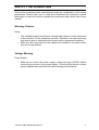
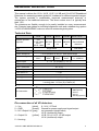
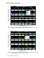
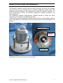
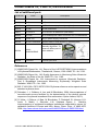
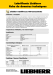
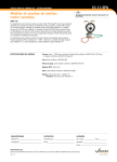
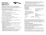
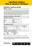
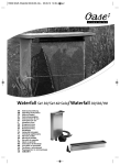
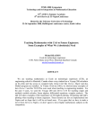
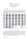
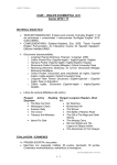
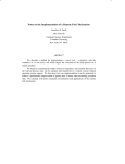
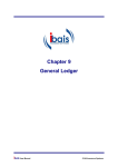
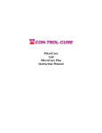
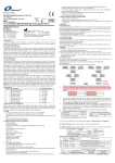
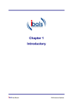
J1034-UV-A/B/E DETECTOR USER’S MANUAL CM S I ng. Dr. Schreder Gm bH Lofererstraße 32, A-6322 Kirchbichl Tel.: +43 / (0)5332 / 77056-00 Fax.: +43 / (0)5332 / 77056-14 E-Mail: [email protected] Web.: www.schreder-cms.com CMS Ing. Dr. Schreder GmbH J1034 Version 1.0.0 First printed January 2011, this revision October 2015 Copyright 2011-2016 by CMS Ing. Dr. Schreder GmbH. All rights reserved Purchasers may make one copy of the software disk for backup purposes. The software may not be copied or distributed in any other way. No part of this manual may be reproduced or transmitted in any form or by any means, electronic, optical or mechanical, including photocopying and recording, or by any information storage and retrieval system, without permission in writing from CMS Ing. Dr. Schreder GmbH. TABLE OF CONTENTS TABLE OF CONTENTS .........................................................................................................I USER INFORMATION...........................................................................................................1 W ARRANTY ..........................................................................................................................1 CONTACT INFORMATION ........................................................................................................1 SAFETY INFORMATION.......................................................................................................2 W ARNING /CAUTION .............................................................................................................2 VOLTAGE W ARNING ..............................................................................................................2 GENERAL DESCRIPTION ....................................................................................................3 TECHNICAL DATA .................................................................................................................3 PIN CONNECTION OF ALL UV DETECTORS ................................................................................3 RELATIVE SPECTRAL RESPONSE ............................................................................................4 MOUNTING AND ALIGNMENT.............................................................................................5 COMPONENTS, PARTS, REFERENCE................................................................................6 LIST OF ADDITIONAL PARTS ....................................................................................................6 REFERENCES .......................................................................................................................6 J1034-UV-A/B/E DETECTOR Manual i USER INFORMATION Thank you for using the UV broadband detector. Make sure to read this instruction manual thoroughly and to understand the contents before starting to operate the instrument. Keep this manual at safe and handy place for whenever it is needed. For any questions, please contact us at the CMS office given below. CMS reserve the right to make changes to specifications without prior notice. Warranty For warranty terms and conditions, contact CMS or your distributor for further details. CMS guarantees that the product delivered to customer has been verified, checked and tested to ensure that the product meets the appropriate specifications. The product warranty is valid only if the product has been installed and used according to the directives provided in this instruction manual. CMS shall in no event be liable for incidental or consequential damages arising from the faulty and incorrect use of the product. In case of any manufacturing defect, the product will be repaired or replaced under warranty. However, the warranty does not apply if: • • Any modification or repair was done by any person or organization other than CMS service personnel. The damage or defect is caused by not respecting the instructions of use as given on the product brochure or the instruction manual. Contact Information CMS Ing. Dr. Schreder GmbH Lofererstraße 32 6322 Kirchbichl Austria Tel.: Fax: +43 (0)5332 / 77056-00 +43 (0)5332 / 77056-14 E-Mail: [email protected] Web: www.schreder-cms.com J1034-UV-A/B/E DETECTOR Manual 1 SAFETY INFORMATION This product is designed and manufactured under the consideration of the safety precautions. Please make sure to read and understand this instruction manual thoroughly in order to be able to operate the instrument safely and in the correct manner. Warning /Caution Setup • • The installation base should have enough load capacity for the instrument to be mounted. Fix the equipment securely. Otherwise, the instrument may drop due to gale or earthquake which may lead to unexpected accidents. Make sure the instrument and the cables are installed in a location where they will not get soaked. Voltage Warning Power Supply • Make sure to check the power supply voltage and type (AC/DC) before connecting the device to the power supply. Connecting the device to other power supplies than specified will lead to damage and accidents J1034-UV-A/B/E DETECTOR Manual 2 GENERAL DESCRIPTION This manual outlines the UV-A, UV-B, UV-E, UV-AB and UV-A/UV-E Broadband Detectors for measuring precise global UV irradiance for different spectral ranges. The system provides a considerably improved measurement accuracy in comparison to the traditional detectors. The direct cosine error f2 is typically less than 1.5%. The detectors are flexible enough to be easily installed on every measurement site. Detector base plates for individual alignment work and a shadow ring system ‘ J1033-SCHADOWRING’make an effective meteorological system. Technical Data Relative spectral response UV-E UV-B UV-A UV-AB ISO 17166:1999/ CIE S 007/E: 1998 265-315 nm 310-400 nm 280-400 nm Type Measure range See individual detectors Single band Cosine error f2 Cosine Response UV-A / UV-E Dual band <1.5% < 2.5% between 0°and 70° solar zenith angle 0 – 0.6 0-5 0 - 100 0 – 100 0 – 0.5W/m² W/m² W/m² W/m² W/m² 0 - 100W/m² Signal output 0 - 5 V (on request: 0 - 2.5 V) Temperature range -40 °C ÷ +60 °C Temp. coefficient 0.1 % / K Power Supply 9 - 24 V / 0.75mA Time switch on < 1 sec Linearity < 1% Housing Anodised aluminium, Quartz glass dome Dimension 80 mm (diameter D) x 88mm (height H) Leveling plate: 115 mm (D) x 88mm (H) Weight < 1 kg 1: Vcc (white) 2: GND (brown) 3: UV-EAE 4: UV-AAE 5: Housing (screen) Pin connection Pin connection of all UV detectors 1 – Vcc [white] 2 – GND [brown] 3 – N.C./Output UV [gray] 4 – Output UV [yellow] 9 - 24 V / 0.75mA Ground for power supply and signal output not connected (single band) UV-E (dual band) output UV-B, UV-A, UV-E, UV-AB output UV-A (dual band) output 5 – Housing J1034-UV-A/B/E DETECTOR Manual 3 Relative Spectral Response 0 RELATIVE SPECTRAL RESPONSE 10 -1 10 ERY UV-E UV-B UV-A UV-AB -2 10 -3 10 -4 10 260 280 300 320 340 WAVELENGTH [nm] 360 380 400 Figure 1 Relative Spectral Response of the single band detectors. Erythemal weighting function ERY defined @ ISO 17166:1999/ CIE S 007/E: 1998. 0 RELATIVE SPECTRAL RESPONSE 10 -1 10 ERY UV-E AE UV-A AE -2 10 -3 10 -4 10 260 280 300 320 340 WAVELENGTH [nm] 360 380 400 Figure 2 Relative Spectral Response of the dual band detector. Erythemal weighting function ERY defined @ ISO 17166:1999/ CIE S 007/E: 1998. J1034-UV-A/B/E DETECTOR Manual 4 MOUNTING AND ALIGNMENT The Detector should be aligned with the help of the spirit level and the montage screw and fixing screw. The sprit level is mounted inside the levelling plate. The following picture illustrates the components to align the detector correctly. To avoid measurement errors, the detector should be carefully levelled in the horizontal plane. The additional available Detectorbase (105303) allows a robust and quick alignment of the detector do individual grounds. Use the tilting screws to align the detector and control the correct settings with the help of the spirit level. After that use the montage screws to fix the detector to the ground. TILTING SCREW MONTAGE SCREW SPIRIT LEVEL Figure 3 UV detector mounted on Detectorbase (Art.No.: 105103) This part fits ideally to the J1033-Shadowring, which can be seen on the next page. J1034-UV-A/B/E DETECTOR Manual 5 COMPONENTS, PARTS, REFERENCE List of additional parts Order No Parts Description 103401 UV-A UV-A radiometer 103404 UV-B UV-B radiometer 103406 UV-E UV-E radiometer (erythemally weighted) 103410 UV-AB UV-AB radiometer 103411 UV-A/UV-E UV-A and UV-E radiometer (dual band) 103402 UV-10m 10 m weatherproof Cable connection for UV radiometers 105102 Power 12V Plug in power supply 12VDC/2A 105103 DETECTORBASE Detector base to hold detector in selected place 103304 J1033SHADOWRING 100229 Circlevel1 Shadow ring for manually alignment. To measure diffuse part of solar radiation Circular spirit level References [1] WMO/GAW Report No. 141: Report of the LAP/COST/WMO Intercomparison of Erythemal Radiometers, Thessaloniki, Greece, 1999. WMO TD – No. 1051. [2] WMO/GAW Report No. 146: Quality Assurance in Monitoring Solar Ultraviolet Radiation: the State of the Art. WMO TD – No. 1180. [3] WMO/GAW Report No. 164: Instruments to measure Ultraviolet Radiation, Part 2: Broadband Instruments Measuring Erythemally Weighted Solar Radiation. WMO TD – No. 1289. [4] ISO 17166:1999 / CIE S 007/E-1998: Erythema reference action spectrum and standard erythema dose. [5] Schreder, J., J. Gröbner, A. Los, and M. Blumthaler, 2004: Intercomparison of monochromatic source facilities for the determination of the relative spectral response of erythemal broadband filter radiometers. Optics Letters, 29(13). [6] G. Hülse, J. Gröbner, A. Bais, M. Blumthaler, P. Disterhoft, B. Johnsen, K.O. Lantz, C. Meleti, J. Schreder, J.M. Vilaplana Guerro, L. Ylianttila: Intercomparison of erythemal broadband radiometers calibrated by seven UV calibration facilities in Europe and USA. Atmos. Chem. Phys., 8, 4865-4875, 2008. http://www.atmos-chem-phys.net/8/4865/2008/acp-8-4865-2008.html. J1034-UV-A/B/E DETECTOR Manual 6