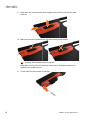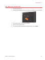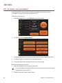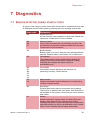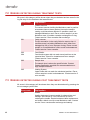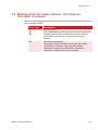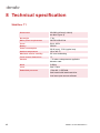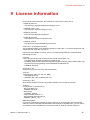
1
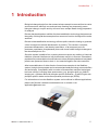
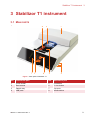
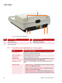
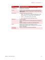
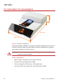
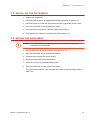
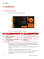
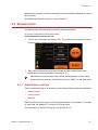
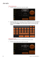
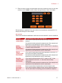
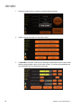
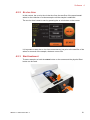
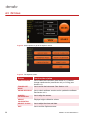
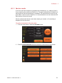
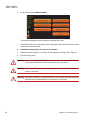
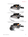
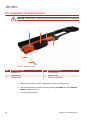
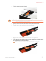
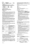
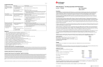
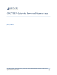
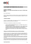
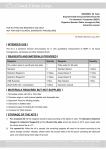
User Manual
Content
1
Introduction . . . . . . . . . . . . . . . . . . . . . . . . . . . . . . 5
2
Safety information . . . . . . . . . . . . . . . . . . . . . . . . . 6
2.1
2.2
DISCLAIMER . . . . . . . . . . . . . . . . . . . . . . . . . . . . . . . 6
IMPORTANT USER INFORMATION . . . . . . . . . . . . . . . . 6
2.2.1 Intended use . . . . . . . . . . . . . . . . . . . . . . . . . . . . . 6
2.2.2 Warning, caution and note definitions. . . . . . . . . . 6
2.2.3 Recycling . . . . . . . . . . . . . . . . . . . . . . . . . . . . . . . 7
2.3
3
LIST OF WARNINGS AND CAUTIONS . . . . . . . . . . . . . . 8
Stabilizor T1 instrument . . . . . . . . . . . . . . . . . . . . 9
3.1
MAIN PARTS . . . . . . . . . . . . . . . . . . . . . . . . . . . . . . . 9
3.1.1 Functions and descriptions of main parts . . . . . . 10
3.2
3.3
3.4
4
INSTRUMENT SITE REQUIREMENTS . . . . . . . . . . . . . 12
INSTALLING THE INSTRUMENT . . . . . . . . . . . . . . . . . 13
MOVING THE INSTRUMENT . . . . . . . . . . . . . . . . . . . . 13
Software . . . . . . . . . . . . . . . . . . . . . . . . . . . . . . . . 14
4.1
4.2
GENERAL FUNCTION . . . . . . . . . . . . . . . . . . . . . . . . 14
RUNNING MODE . . . . . . . . . . . . . . . . . . . . . . . . . . . 15
4.2.1
4.2.2
4.2.3
4.2.4
4.2.5
4.3
Stabilization settings . . . . . . . . . . . . . . . . . . . . . . 15
Ex vivo time. . . . . . . . . . . . . . . . . . . . . . . . . . . . . 20
Start treatment . . . . . . . . . . . . . . . . . . . . . . . . . . 20
Sample treatment . . . . . . . . . . . . . . . . . . . . . . . . 21
Log files. . . . . . . . . . . . . . . . . . . . . . . . . . . . . . . . 22
OPTIONS . . . . . . . . . . . . . . . . . . . . . . . . . . . . . . . . 23
4.3.1 Service mode . . . . . . . . . . . . . . . . . . . . . . . . . . . 24
4.3.2 Transport mode. . . . . . . . . . . . . . . . . . . . . . . . . . 25
4.3.3 Software upgrade . . . . . . . . . . . . . . . . . . . . . . . . 26
5
Heat-stabilizing tissue samples . . . . . . . . . . . . . 27
5.1
PREPARATIONS . . . . . . . . . . . . . . . . . . . . . . . . . . . 27
5.1.1 Starting the instrument . . . . . . . . . . . . . . . . . . . . 27
5.1.2 Preparing the Maintainor card. . . . . . . . . . . . . . . 27
Stabilizor T1 DPM 0008 Edition 3
3
5.1.3 Preparing the Instrument. . . . . . . . . . . . . . . . . . 28
5.2
SAMPLE COLLECTION AND HEAT STABILIZATION . . . . 28
5.2.1 Sample collection . . . . . . . . . . . . . . . . . . . . . . . 28
5.2.2 Sample stabilization . . . . . . . . . . . . . . . . . . . . . 29
5.3
5.4
6
Maintenance . . . . . . . . . . . . . . . . . . . . . . . . . . . . . 32
6.1
6.2
6.3
6.4
6.5
7
MAINTENANCE AND SERVICE . . . . . . . . . . . . . . . . .
CHANGING THE O-RING . . . . . . . . . . . . . . . . . . . . .
CHANGING THE NEEDLE DEVICE . . . . . . . . . . . . . . .
REPLACE THE BATTERY . . . . . . . . . . . . . . . . . . . . .
CLEANING THE INSTRUMENT . . . . . . . . . . . . . . . . .
32
32
35
38
39
Diagnostics . . . . . . . . . . . . . . . . . . . . . . . . . . . . . . 40
7.1
7.2
7.3
7.4
8
LOG FILES . . . . . . . . . . . . . . . . . . . . . . . . . . . . . . . 30
EXTRACTION OF PROTEINS FROM HEAT-STABILIZED
TISSUE SAMPLES . . . . . . . . . . . . . . . . . . . . . . . . . . 30
ERRORS DETECTED DURING STARTUP TESTS . . . . . 40
ERRORS DETECTED DURING TREATMENT TESTS . . . 41
ERRORS DETECTED DURING POST TREATMENT TESTS 41
ERRORS DETECTED DURING PERIODIC TEST WHEN NO
TREATMENT IS RUNNING . . . . . . . . . . . . . . . . . . . . . 42
Technical specification . . . . . . . . . . . . . . . . . . . . 43
Stabilizor T1 . . . . . . . . . . . . . . . . . . . . . . . . . . . . . . . . . 43
9
License information . . . . . . . . . . . . . . . . . . . . . . . 44
10
Ordering information . . . . . . . . . . . . . . . . . . . . . . 46
NOTES . . . . . . . . . . . . . . . . . . . . . . . . . . . . . . . . . . . . . . . . . . . 46
4
Stabilizor T1 DPM 0008 Edition 3
Introduction 1
1 Introduction
Biological changes begin from the moment a tissue sample is removed from its native
environment and, although conventional snap freezing may temporarily pause
biological change, enzyme activity will return as a sample thaws during preparation
for analysis.
Denator has developed an additive-free heat-stabilization technology that preserves
the quality of biological tissue samples from moment of excision throughout the entire
workflow.
Denator's heat-stabilization technology utilizes rapid conductive heating to generate
a fast, homogenous thermal denaturation of proteins. This results in complete,
permanent denaturation, and thereby inactivation, of all enzymes (such as
proteases, peptidases, phosphatases) that could cause further biological changes to
the tissue sample ex vivo.
Since the system is additive-free, meaning does not require any addition of chemical
inhibitors, potential interference with downstream analysis is removed. Biomarkers,
peptides and posttranslational modifications such as phosphorylated and acetylated
proteins are preserved close to their in vivo state throughout the entire workflow.
After heat stabilization of either fresh or frozen tissue samples in the Stabilizor
system, biological components can be extracted and analyzed using common buffers
and techniques. Compatibility with a number of downstream analytical techniques
has been verified, including mass spectrometry (e.g. phospho-shot gun, MALDI
Imaging etc.), Western Blot with phospho-specific antibodies, 1D and 2D gels with
phospho-specific stains and reversed phased protein arrays (RPPA).
For information on how the Stabilizor system can be utilized in different applications,
please visit Denator’s website www.denator.com or contact us at
[email protected].
Stabilizor T1 DPM 0008 Edition 3
5
2 Safety information
2.1 DISCLAIMER
Denator will use reasonable efforts to include accurate and up-to-date information in
this document. Denator makes no warranties or representations of any kind as to the
accuracy, completeness or usefulness of the information. The information shall not
be considered to constitute a warranty or representation of any kind, legal or other,
or a quality specification. Neither Denator nor any party involved in creating,
producing or delivering this document shall be liable for any damages arising out of
use of this document, or any errors or omissions in the content thereof.
Stabilizor™ and Maintainor™ are trademarks of Denator AB. All other trademarks
are the property of their respective owners. Products and technologies from Denator
are patent pending. All infringements are prohibited and may be prosecuted. Please
contact Denator AB for further details. Products are for research use only.
© Denator AB 2013
2.2 IMPORTANT USER INFORMATION
2.2.1 Intended use
Stabilizor T1 and all associated products from Denator AB are for research use only.
Do not use in diagnostic procedures for clinical purposes.
2.2.2 Warning, caution and note definitions
Warning: A warning indicates that there is a risk of personal injury if the instructions
are not followed. It is very important to address all safety issues stated in
Warnings.
Caution: A caution indicates that there is a risk of damaging the instrument if the
instructions not are followed. It is important to address all issues stated in
Cautions in order to keep your equipment in good condition.
A note indicates important information for improving your results or facilitating
your work.
6
Stabilizor T1 DPM 0008 Edition 3
Safety information 2
2.2.3 Recycling
All electrical and electronic equipment must not be disposed as unsorted municipal
waste and must be collected separately.
Please contact an authorized representative of the manufacturer for information
concerning the decommissioning of equipment.
Stabilizor T1 DPM 0008 Edition 3
7
2.3 LIST OF WARNINGS AND CAUTIONS
Warning: This is a Class A product. In a domestic environment, it might cause radio
interference, in which case the user might be required to take appropriate
measures.
Warning: No user serviceable parts inside. All repairs should be done by personnel
authorized by Denator. Do not open any covers or replace parts unless
specifically stated in the instructions.
Warning: Do not block the rear panel of the instrument. The power switch must
always be easily accessible.
Warning: Hot parts inside! Do not remove the top cover unless the instrument has
been turned off and allowed to cool down for 30 min.
Warning: Hazardous voltage! Stabilizor T1 contains mains voltage of up to 240 VAC.
Disconnect power cord before removing the top cover.
Warning: Laser inside! The instrument must always be turned off before the top
cover is removed.
Warning: Sharp needle. To avoid injury, take care when handling the needle device.
Warning: Ensure that all instrument site requirements are fulfilled before starting the
instrument.
Caution: Handle the needle device carefully to avoid bending the needle.
Caution: The instrument can be damaged if the instructions for moving the
instrument are not followed.
Caution: Do not put the Maintainor card into liquid nitrogen! The Maintainor card
withstands temperatures down to -80 °C.
8
Stabilizor T1 DPM 0008 Edition 3
Stabilizor T1 instrument 3
3 Stabilizor T1 instrument
3.1 MAIN PARTS
8
1 2
5
6
7
3
4
Figure 1. Main parts of Stabilizor T1
No. Instrument part
No. Instrument part
1
Touch screen
5
Illumination
2
Start buttons
6
Ex vivo button
3
Sample tray
7
Top cover
4
USB ports
8
Needle device
Stabilizor T1 DPM 0008 Edition 3
9
11
12 13
10
9
Figure 2. Main parts of Stabilizor T1.
No. Instrument part
No. Instrument part
9
Power switch
12
Ethernet connection
10
Power connection
13
Accessory connection
11
Top cover screws
3.1.1 Functions and descriptions of main parts
Part
Touch screen
Function/description
Displays the control software and command buttons, see
Section 4 for detailed information.
10
Ex vivo button
Resets/Restarts the ex vivo timer.
Start button
Starts the stabilization process.
Sample tray
Holds the Maintainor card and moves the Maintainor card into
and out of the heating block compartment.
Maintainor card
Container for the sample during the heating process and
after.
Needle parts
•
Needle device – Penetrates the vacuum seal to remove
air from the Maintainor card.
•
Needle holder and Needle guide – Holds the needle
device in the correct position.
•
Needle shuttle lever – Moves the needle device into
and out from the vacuum channel of the Maintainor card.
Stabilizor T1 DPM 0008 Edition 3
Stabilizor T1 instrument 3
Part
Function/description
Heating
compartment
Chamber for the heating blocks with a controlled
temperature environment.
O-ring
Contact vacuum seal placed on the lower heating block for
optimal contact between the Maintainor card and the lower
heating block.
Illumination
Indicates treatment process status:
USB port
•
Blue – The instrument is ready and a Maintainor card
can be placed in or removed from the sample tray.
•
Green – The sample cycle is processed.
•
Red – The instrument is initializing or busy.
3 ports available.
Used for USB flash drive to collect and store the treatment
log file.
Software updates are installed via a USB flash drive.
Laser
Measure the thickness of the sample to ensure
reproducibility by adjusting the stabilization time to optimize
sample stabilization.
Accessory
connection
Used for connection of external accessories.
Stabilizor T1 DPM 0008 Edition 3
11
143 mm
3.2 INSTRUMENT SITE REQUIREMENTS
465 mm
306 mm
Figure 3. Dimensions of Stabilizor T1
For proper operation, Stabilizor T1 requires an ambient temperature of 10 to 40 °C
and 80% maximum relative humidity. Make sure there is adequate air circulation
around the instrument. For indoor use only.
Warning: Do not block the rear panel of the instrument. The power switch must
always be easily accessible.
Power requirements
•
Mains voltage: 100-240 VAc (auto range), 50-60 Hz.
12
•
Connect only to grounded power outlets!
•
Power consumption: 350 W (max), 70 W (typical use).
•
Use a slow 20×5 mm ceramic fuse T4A H that holds for 250V.
Stabilizor T1 DPM 0008 Edition 3
Stabilizor T1 instrument 3
3.3 INSTALLING THE INSTRUMENT
3.4
1
Unpack the instrument.
2
Place the instrument on an appropriate surface according to Section 3.2.
3
Insert the power cord into the instrument and into a grounded power outlet.
4
Turn the instrument on using the power switch.
5
The instrument will perform a self test. Wait until it is done.
6
The instrument is ready for use when the initial screen is lit.
MOVING THE INSTRUMENT
Caution: The instrument can be damaged if the instructions for moving the
instrument is not followed.
1
Set the instrument to transport mode, see Section 4.3.2.
2
Turn the instrument off using the power switch.
3
Remove the cord from the power socket.
4
Move the instrument to the new location.
5
Insert the cord into a grounded power outlet.
6
Turn the instrument on using the power switch.
The instrument performs a self test and then stops in running mode, ready to
start a run.
Stabilizor T1 DPM 0008 Edition 3
13
4 Software
4.1 GENERAL FUNCTION
Stabilizor T1 is controlled via the touch screen.
7
1
2
8
3
9
4
5
6
10
11
Figure 4. The touch screen of Stabilizor T1, main screen
No. Description
No. Description
1
Current date and time
7
Buttons with editable text
2
Heating block temperatures
(set, upper and lower)
8
Ex vivo button with ex vivo time
3
Selected method
9
Method selection button
4
External USB flash drive connected
10
Start button
5
Error message symbol
11
Options button
6
Ex vivo time
To edit card name or card number, press the button to display a key pad view. To
select method, press the method selection button to display a new view with selection
buttons. For detailed information, see Section 4.2.1.
The ex vivo button display the current ex vivo time. Press the button to reset the ex
vivo time.
Press the error message symbol to display the error message.
To the left, there is current information: time, date, heating block temperature and
selected method. All sample data is saved and can be viewed later, see
Section 4.2.5.
14
Stabilizor T1 DPM 0008 Edition 3
Software 4
Maintenance requests and failure messages are automatically displayed on screen
when needed.
See additional information Section 4.3 and Section 6.
4.2 RUNNING MODE
In running mode, the instrument is ready for stabilizing samples.
To set the instrument in Running mode
If the instrument is not turned on:
1
Turn on the instrument (see Section 3.3). The instrument automatically enters
Running mode, displaying the main screen.
2
Wait until the startup sequence has finished and the heating blocks have
reached the correct temperature (normally 95 °C).
Stabilization cannot be performed until the set temperature of the heating
blocks has been reached, as indicated by the text “WAIT” on the start button.
4.2.1 Stabilization settings
There are three settings to be entered for each sample before starting a stabilization:
•
Sample name
•
Card number
•
Method
Data is entered on the screen, via the key pad available in the software. To be able
to enter data, the Stabilizor T1 must be in running mode.
The information is saved in the log file (see Section 4.2.5).
Stabilizor T1 DPM 0008 Edition 3
15
Enter sample name
1 Press the sample name text to open the keypad.
2
Enter the sample name. If required, press the 123# selection button to be able to
enter digits and symbols. Press OK to save the name and return to the main
screen or press NUMBER to save name and go directly to entering the card
number.
Enter card number
All Maintainor cards have room for customer IDs and/or bar codes.
1
16
Press the card number text to open the key pad.
Stabilizor T1 DPM 0008 Edition 3
Software 4
2
Enter the card number and press OK to save the number and return to the main
screen or press NAME to save number and go directly to enter card name.
Once a sample is stabilized, the card number is automatically increased with 1 to
simplify the settings for next sample.
Set method
There are five different stabilization methods and one method for vacuum treatment.
Method
Recommended use and description
QUICK FRESH To be used for fresh tissue that does not need to keep its
(COMPRESS) structure.
The method includes automatic measurement of the sample and
adjustment of the stabilization time for inactivation.
QUICK
FROZEN
(COMPRESS)
To be used for all tissue below +20 °C, down to -80 °C, that does
not need to keep its structure.
FRESH
(STRUCTURE
PRESERVE)
To be used for fresh tissue that should maintain its structure, i.e.
that must be minimally compressed.
FROZEN
(STRUCTURE
PRESERVE)
To be used for all tissue below +20 °C, down to -80 °C, that
should maintain its structure, i.e. that must be minimally
compressed.
The method includes automatic measurement of the sample and
adjustment of the stabilization time for inactivation.
The method includes automatic measurement of the sample and
adjustment of the stabilization time for inactivation.
The method includes automatic measurement of the sample and
adjustment of the stabilization time for inactivation.
CUSTOM
Manual mode where all parameters can be set by the user.
CUSTOM >
VACUUM
PACK
To be used for setting a sample under vacuum without heating.
Stabilizor T1 DPM 0008 Edition 3
(Can be used before re-freezing previous stabilized samples)
17
18
1
Press the method text to open the method selection dialog.
2
Select method and return to the main screen.
3
If CUSTOM is selected, continue with setting the parameters on the new screen
before pressing OK to return to the main screen. In custom all parameters are
set individually and no algorithms is present.
Stabilizor T1 DPM 0008 Edition 3
Software 4
4.2.2 Ex vivo time
In this context, the ex vivo time is the time from the sacrifice of the experimental
animal or the collection of a tissue sample until the sample is stabilized.
The ex vivo time is reset to zero by pressing the ex vivo button on the screen.
It is important to start the ex vivo time measurement just prior to the sacrifice of the
animal or removal of the sample, whatever occurs first.
4.2.3 Start treatment
To start a sample run both the START button on the screen and the physical Start
button can be used.
Stabilizor T1 DPM 0008 Edition 3
19
4.2.4 Sample treatment
During sample treatment the progress is shown on the screen.
Press CARD INFO to update card name and card number for the sample in process
during sample treatment.
20
Stabilizor T1 DPM 0008 Edition 3
Software 4
4.2.5 Log files
A log file including information on the samples are automatically saved to an external
USB flash drive if inserted.
If no external USB flash drive is inserted into the instrument, the log file is saved on
the internal USB flash drive until one is inserted. A large number of stabilization runs
can be saved on the internal USB flash drive.
To minimize the risk of accidental loss of log-data due to any unexpected
failure, always have an external USB flash drive inserted into the instrument.
The log file, marked with the date (e.g. 2012-06-17.xls), is saved into a folder called
Denator, created by the software. All runs during a day are saved into the same log
file.
The log file includes the following data for each sample: Time, Sample name,
Maintainor ID(s), Ex vivo time, Run time, SET Temperature, Actual Temperature,
Vacuum, Sample height, Method used and Comments.
The log files are saved as Microsoft Excel spreadsheet (xls).
Stabilizor T1 DPM 0008 Edition 3
21
4.3 OPTIONS
Figure 5. Press Options to get to the Options screen.
Figure 6. The Options screen.
Button
Function/description
SERVICE MODE
Use to clean the instrument (see Section 4.3.1) and/or
change needle device (see Section 6.3) or O-ring (see
Section 6.2).
Use to move the instrument. See Section 4.3.2.
TRANSPORT
MODE
22
HW/SW REVISION
Use to check software version and to update the software.
See Section 4.3.3.
SCREEN
CALIBRATION
Use to align the screen.
HEIGHT
CALIBRATION
Displays height calibration values.
ADJUST CLOCK
Use to adjust the time and date.
EXIT
Use to exit the Options screen.
Stabilizor T1 DPM 0008 Edition 3
Software 4
4.3.1 Service mode
In service mode the instrument is prepared for maintenance, e.g. change of the Oring or replacing the needle (see Section 6). The upper heating block is raised to an
extra high level and the sample tray is released. The instrument will not move any
parts when in service mode. However, it is recommended to turn the instrument off
after setting it into service mode.
Service mode should also be used when cleaning is needed, or if something is
dropped into the instrument.
To set the instrument in Service mode
1 From the main screen, press the OPTIONS button.
2
Press the SERVICE MODE button and follow the instructions on the screen.
Stabilizor T1 DPM 0008 Edition 3
23
4.3.2 Transport mode
When the instrument needs to be moved, Transport mode should be used.
It is recommended that transport mode is used during longer storage periods
to avoid damage to the sample tray and needle.
To set the instrument in Transport mode
1 Place a closed, empty Maintainor Tissue card on the sample tray.
2
From the main screen, press the OPTIONS button.
3
Press the TRANSPORT MODE button.
4
Follow the instructions on the screen.
5
Move the instrument according to Section 3.4.
Storage
Stabilizor T1 should be stored in +10 to +40 °C and max 80% relative humidity.
24
Stabilizor T1 DPM 0008 Edition 3
Software 4
4.3.3 Software upgrade
Software upgrades will be distributed by Denator.
Caution: Do NOT turn off the instrument during the upgrade as this may cause
irreversible malfunction.
1
Remove any inserted USB flash drives before starting the upgrade.
2
Copy the program file [DST0001_SPxxxx.jar] to root level of a USB flash drive.
Make sure the file is named [DST0001_SPxxxx.jar]. No un-zipping of the file is
needed and no .zip extension should be added. 3
Insert the USB flash drive with the upgraded software.
4
Wait until the USB symbol appears on the screen
seconds).
5
Press the OPTIONS button.
6
Press the HW/SW REVISION button. Document the current version of software.
7
Press the UPDATE button.
8
Let the installation run. Do NOT turn off the instrument during the update.
9
The installation is successfully completed when the text “Restart the instrumentupdate complete” appears on the screen.
(approximately 10
10 Restart the instrument using the power switch.
Stabilizor T1 DPM 0008 Edition 3
25
5 Heat-stabilizing tissue samples
5.1 PREPARATIONS
5.1.1 Starting the instrument
Warning: Ensure that all instrument site requirements, including a grounded power
outlet, are fulfilled before starting the instrument (see Section 3.2).
1
Insert a USB flash drive (for the log file) in a USB port.
2
Turn the instrument on using the power switch.
3
The system check is automatically performed. During the system check the
illumination is first red, while the sample tray is moved in and out, and then
changes to blue. The heating blocks are heated to the set temperature.
The sample tray can move unexpectedly.
The system check and heating of the heating blocks will take 3 - 5 minutes,
depending on available voltage. The main screen is displayed when the system
check is finished.
5.1.2 Preparing the Maintainor card
1
Figure 7. Maintainor card
1
26
Prepare the Maintainor card by writing the sample ID and card ID at (1) shown
in Figure 7.
Stabilizor T1 DPM 0008 Edition 3
Heat-stabilizing tissue samples 5
5.1.3 Preparing the Instrument
Enter settings for the run according to Section 4.2.1.
5.2 SAMPLE COLLECTION AND HEAT STABILIZATION
5.2.1 Sample collection
1
Open the Maintainor card fully one time to avoid unwanted closing of the card
when loading the sample. Place the card depending on the sample type.
•
Fresh sample: Place the Maintainor card directly in the Stabilizor T1 before
collecting the sample. This will give the shortest ex vivo time
•
Frozen sample: Place the Maintainor card on ice to keep the sample cold
before the stabilization.
Caution: Do not put the Maintainor card into liquid nitrogen! The Maintainor card
withstands temperatures down to -80 °C.
2
Start the measurement of the ex vivo time just prior to sampling by pressing the
ex vivo button on the screen and immediately continue with step 3.
3
Collect a sample of appropriate size.
Stabilizor T1 DPM 0008 Edition 3
27
4
Put the sample in the center of the sample chamber of the Maintainor card.
5
Close the Maintainor card by pressing the lid down. Ensure that the lid has
sealed completely by gently pressing down the cover lid encircling the sample
chamber using one or two fingers.
Caution: Do not press the inner edge of the cavity. The upper plastic can be
damaged leading to leakage of air during the heating process.
5.2.2 Sample stabilization
Immediately start the heat-stabilization process:
6
28
If not already done, place the Maintainor card in the sample tray.
Stabilizor T1 DPM 0008 Edition 3
Heat-stabilizing tissue samples 5
7
Start the run by pressing the start button above the screen, or by pressing
START on the screen.
8
During stabilization, air is evacuated from the card, the sample is moved
automatically into the heating compartment and treated according to set
parameters.
9
When the sample tray returns to the starting position, and the illumination turns
green, remove the Maintainor card from the tray.
10 Check that there is vacuum in the sample compartment (no vacuum indicates
need of needle device change or remounting of the needle device).
11 When the heat stabilization process is done, store the Maintainor card with the
heat-stabilized sample at -80 °C for long term storage or prepare sample for
analysis.
Caution: Do not put the Maintainor card into liquid nitrogen! The Maintainor card
can only withstand temperatures down to -80 °C.
12 The next sample, if prepared, can be heat stabilized as soon as the processed
Maintainor card has been removed.
5.3 LOG FILES
Log files are automatically saved on the USB flash drive, see Section 4.2.5.
5.4 EXTRACTION OF PROTEINS FROM HEAT-STABILIZED
TISSUE SAMPLES
To ensure the most efficient extraction of proteins from heat-stabilized tissue
samples, the following must be observed:
1
Use a denaturing buffer (>8M Urea, >1% SDS, >6M GuHCl)
Buffers based on >8M urea, >6M GuHCl or >1% SDS have proven to be effective.
When using SDS buffers, it is recommended to maximize their effectiveness by
Stabilizor T1 DPM 0008 Edition 3
29
adding heated buffer (>90 °C) to the sample, preferably followed by a second
homogenization step using ultrasonication. Other components such as detergents
and buffering agents can be added as long as the concentrations of the denaturing
agents are not affected.
2
Use a buffer-to-sample ratio greater than 10 (>10 μl buffer/mg sample)
For maximum extraction efficiency it is important to add at least 10 times the amount
of sample, i.e. 10 μl of buffer for each mg of sample.
3
Ensure thorough homogenization using ultrasonication, grinding or ball mill
Although heat-stabilized samples will usually homogenize easily, it is very important
to ensure that the initial homogenization step is extremely thorough to facilitate the
resolubilization of proteins. Softer tissue types, such as brain, can be homogenized
using a microtip sonication rod, whereas a micropestle grinding or ball mill should be
used for firmer tissue types such as liver or heart.
Specific protocols for heat stabilization, homogenization and extraction prior to LCMS
or 2D-GE analysis are supplied with the Stabilizor Peptide Extraction Kit and
Stabilizor 2D-GE Extraction Kit respectively.
Additional recommendations for other analytical downstream analysis can be
retrieved at www.denator.com or via [email protected].
30
Stabilizor T1 DPM 0008 Edition 3
Maintenance 6
6 Maintenance
6.1 MAINTENANCE AND SERVICE
Service of Stabilizor T1 should be performed by service engineers from Denator.
Contact information to Denator is provided on the back cover.
The following maintenance can be performed by the customer.
•
Changing the O-ring including cleaning heat blocks (see Section 6.2)
•
Changing the needle device (see Section 6.3)
•
Cleaning the instrument (see Section 6.5)
The Stabilizor T1 should always be put into service mode (see Section 4.3.1) before
performing any maintenance or cleaning.
6.2 CHANGING THE O-RING
For optimal contact, and thereby heat transfer, between the lower heating block and
the Maintainor card during stabilization, the space between the two parts, sealed by
an O-ring, is evacuated during the stabilization.
1
With the Stabilizor T1 instrument turned on, press OPTIONS in the main screen.
Stabilizor T1 DPM 0008 Edition 3
31
2
In next view, press SERVICE MODE.
The upper heating block will be lifted to an extra high level.
3
Turn off the instrument using the Power switch (as instructed on the screen) and
disconnect the mains cord.
4
Allow the heating block to cool for 30 minutes.
5
Remove the two screws on the back of the instrument using a Torx T20 tool.
6
Lift off the top cover.
Warning: Hazardous voltage! Stabilizor T1 contains mains voltage of up to 240 V ac.
Disconnect the power cord before removing the top cover.
Warning: Laser inside! The instrument must always be turned off when the top
cover is removed.
Warning: Hot parts inside! Do not remove the top cover unless the instrument has
been turned off and allowed to cool down for 30 minutes.
32
Stabilizor T1 DPM 0008 Edition 3
Maintenance 6
7
Remove the white O-ring.
8
Clean the heating blocks with a tissue moistened with 70% EtOH.
9
Put on a new O-ring. Make sure that the O-ring is not twisted and that it is fitted
securely in the groove.
Stabilizor T1 DPM 0008 Edition 3
33
6.3 CHANGING THE NEEDLE DEVICE
Warning: Sharp needle. Take care when handling the needle device to avoid injury.
4
3
2
1
5
6
Figure 8. Needle overview
No. Instrument part
No. Instrument part
1
4
Needle guide
Tube interlock
2
Needle holder
5
Vacuum tube
3
Needle device
6
Vacuum connection
34
1
Make sure that there is NOT a Maintainor card in the sample tray.
2
Set the instrument to Service mode by pressing OPTIONS and then SERVICE
MODE, see Section 4.3.1.
3
Turn off the instrument.
Stabilizor T1 DPM 0008 Edition 3
Maintenance 6
4
Push the sample tray gently forward.
Caution: It is only possible to move the sample tray if the instrument was set to
Service mode before it was turned off.
5
Remove the tube from the tube interlock and the vacuum connection.
6
Carefully remove the needle device in the tube direction.
7
Dispose of the needle device in accordance with local regulations.
8
Fit the top of the new needle into the hole of the needle guide and gently insert
the needle device into the needle holder.
Make sure that the needle is inside the hole of the needle guide.
Stabilizor T1 DPM 0008 Edition 3
35
9
Hold down the needle device while snapping the vacuum tube into the tube
interlock.
10 Make sure that the needle device is flush with the needle holder.
Correctly fitted needle device to the left.
Otherwise re-fit the tube into the tube interlock so a downward pressure is
applied to the needle device.
11 Fit the tube into the vacuum connection.
36
Stabilizor T1 DPM 0008 Edition 3
Maintenance 6
6.4 REPLACE THE BATTERY
1
Turn the instrument off.
2
Remove the rubbergasket which gives access to the battery on the internal PC.
3
Exchange the battery with a similar (CR2032).
4
Attach the rubber gasket again.
5
Turn the instrument on and adjust the date and time under OPTIONS.
Stabilizor T1 DPM 0008 Edition 3
37
6.5 CLEANING THE INSTRUMENT
If the instrument or area under the sample tray needs to be cleaned, set the
instrument in service mode, see also Section 4.3.1.
With the instrument on
1 With the instrument on, press OPTIONS in the main screen.
2
In next view, press SERVICE MODE.
3
Wipe the area under the sample tray with a tissue moistened with 70% EtOH.
4
If required, clean the outside of the instrument as well.
5
Follow the instructions on screen to return to running mode.
With the instrument turned off
1 Move the sample tray out of the way manually.
It is only possible to move the sample tray if the instrument was set to Service
mode before it was turned off.
2
38
Clean the area as in step 3 and 4 above.
Stabilizor T1 DPM 0008 Edition 3
Diagnostics 7
7 Diagnostics
7.1 ERRORS DETECTED DURING STARTUP TESTS
All errors in this category will be shown after the self test is completed and can also
be displayed from the status panel by pressing the error message symbol later.
Error code
Explanation
100
Contact Vacuum
Air flow from the lower heatblock is obstructed. Restart the
instrument. Contact service if error remains.
101
102
117
Vacuum system
Cavity vacuum sensors are not performing correctly. Set
the instrument in transport mode and restart the instrument.
Contact service if error remains.
104
Backup battery
Battery power is too low to keep the clock settings between
startups. Replace battery, see Section 6.4 for instructions.
105
Old software
The software has not been updated during the last 10
months. Check the current version under [OPTIONS]
[HW/SW] and compare with latest version at
www.denator.com.
106
107
108
113
115
116
Card shuttle
Card shuttle sensors failed and are therefore not
performing correctly. Contact service.
110
114
Measurement
Height measurement system failed and is not performing
correctly. Contact service.
109
Start button
Physical Start button was not recognized during startup.
The function is disabled until next restart. Note that Start is
still available on the screen. Contact service if error remains
after restart.
111
Needle
Needle obstructed. Inspect needle for obstructions and
damage. See Section 6.3 for instructions on how to
exchange the needle. Restart instrument after replacement,
and make a blank run with a new Maintainor card. Contact
service if error remains after exchange and startup.
Stabilizor T1 DPM 0008 Edition 3
39
7.2 ERRORS DETECTED DURING TREATMENT TESTS
All errors in this category will be shown when they are detected and are saved in the
log file entry for the treatment that was affected.
Error code
Explanation
200
Contact vacuum
The contact vacuum holding the Maintainor card in position
at treatment has not been reached, hence the sample
heating could have been affected. A possible cause is a
damaged Maintainor card. Rerun current sample in a new
Maintainor card. If problem remains exchange the O-ring.
Contact service if error remains after exchange.
201
Cavity vacuum
The air evacuation in the cavity failed or was too low. A
possible cause is a leaking Maintainor card, either from
damaged top foil or from unproper closing. Rerun current
sample in a new Maintainor card to avoid undertreatment.
Contact service if error remains.
202
204
Card Shuttle
Card shuttle system did not reach travel positions at the
expected time. Check for obstacles and rerun sample.
Contact service if error remains.
203
Sample size
The sample size is above the specified size. Contact
Denator application specialist for recommendations on
large sample treatment.
205
Heating System
Upper heater did not reach the calculated position. Rerun
current sample to avoid undertreatment. Contact service if
error remains.
7.3 ERRORS DETECTED DURING POST TREATMENT TESTS
All errors in this category will be shown when they are detected and by pressing the
error message symbol later.
40
Error code
Explanation
300
Needle
Needle obstructed. Inspect needle for obstructions and
damage. See Section 6.3 for instructions on how to
exchange the needle. Restart instrument after replacement,
and make a blank run with a new Maintainor card. Contact
service if error remains after exchange and startup.
Stabilizor T1 DPM 0008 Edition 3
Diagnostics 7
7.4 ERRORS DETECTED DURING PERIODIC TEST WHEN NO
TREATMENT IS RUNNING
All errors in this category can also be displayed from the status panel by pressing the
error message symbol.
Error code
Explanation
400
401
402
Heating system
One of the heating system sensors has reported values out
of specification and is not performing correctly. Restart
instrument to reset sensors. Contact service if error
remains.
403
Instrument temperature
Temperature inside instrument is too high. Shut off the
instrument to cool down. Check that the ambient
temperature is within the specification. Restart the
instrument. Contact service if error remains.
Stabilizor T1 DPM 0008 Edition 3
41
8 Technical specification
Stabilizor T1
Stabilizor T1
Dimensions
465×306×143 mm (L×W×H)
(see also Figure 3)
Net weight
6.7 kg
Mains power requirements
100-240 V/50-60 Hz
Fuses
T4A H, 250V
Battery
CR2032
Power consumption
350 W (max), 70 W (typical use)
Ambient temperature
+10 to +40 °C
Maximum relative humidity
80% non-condensing
Touch screen dimensions
4.3”
Vacuum
2 - 30 mbar underpressure applied to
Maintainor card
Noise
45 dB(A)
Laser
Class 1 laser
Embedded processor
1 GHz x86, 1 GB RAM
Flash based solid state hard drive
Linux base open source software
42
Stabilizor T1 DPM 0008 Edition 3
License information 9
9 License information
License texts referenced below, are included on built in memory stick and at:
LICENCE_GPL2.txt
- http://www.gnu.org/licenses/old-licenses/gpl-2.0.html
LICENCE_LGPL2.1.txt
- http://www.gnu.org/licenses/lgpl-2.1.html
LICENCE_GPL3.txt
- http://www.gnu.org/licenses/gpl.html
LICENCE_RXTX.txt
- http://users.frii.com/jarvi/rxtx/license.html
LICENCE_JAVA.txt
- http://java.sun.com/javase/6/jdk-6u3-license.txt
Component - IO Controller Firmware
The contained firmware of this product uses GPL 2.0 and LGPL 2.1 licenced components and
is itself licenced under GPL 2.0 licence.
Full licence text available on built-in memory card and at http://www.gnu.org/licenses/oldlicenses/gpl-2.0.html
Licences:
* Interrupt UART library with receive/transmit circular buffers (GPL 2.0)
- http://homepage.hispeed.ch/peterfleury/uartlibrary.zip
- LICENCE_GPL2.txt* I2C interface using AVR Two-Wire Interface (TWI) hardware (GPL 2.0)
- http://www.procyonengineering.com/embedded/avr/avrlib/avrlib.zip
- LICENCE_GPL2.txt
Component - OS
The OS of this product uses GPL licensed software.
Licences:
* OS Puppylinux (GPL 2.0, GPL 3.0, BSD)
- http://puppylinux.org/
- LICENCE_GPL2.txt, LICENCE_GPL3.txt
Component - GUI
Some linked components of GUI uses LGPL software, but is closed source itself.
Licences:
* RXTX (LGPL 2.1 & Extensions)
- http://rxtx.qbang.org
- LICENCE_RXTX.txt
* JAVA (Java)
- LICENCE_JAVA.txt
* Java Excel API (LGPL 2.1+)
- http://jexcelapi.sourceforge.net/
- LICENCE_LGPL2_1.txt
WRITTEN OFFER:
For binaries received from Denator on physical device or physical media, that are licensed
under any version of the GNU General Public License (GPL) or the GNU LGPL, you can receive
a complete machine readable copy of the source code by sending a written request to:
Stabilizor T1 DPM 0008 Edition 3
43
Denator
Biotech Center
Arvid Wallgrens Backe 20
SE-413 46 Gothenburg, Sweden
Your request should include (i) the name and version number of the product containing the
covered binary, (ii) your name, (iii) your company (if applicale) and (iv) your return mailing and
email addres (if available).
We may charge you a nominal fee to cover the cost of the media distribution.
Your request must be sent withing (3) years of the release date of the product, or binaries, in
question.
44
Stabilizor T1 DPM 0008 Edition 3
Ordering information 10
10 Ordering information
Product
Order number
Stabilizor T1 Instrument
DST0001
Maintainor Tissue card
DMT0001
Stabilizor T1 Maintenance Kit
DST0016
Stabilizor Peptide Extraction Kit (Tissue)
DKT0001
Stabilizor 2D-GE Extraction Kit (Tissue)
DKT0002
NOTES
__________________________________________________________________
__________________________________________________________________
__________________________________________________________________
__________________________________________________________________
__________________________________________________________________
__________________________________________________________________
__________________________________________________________________
__________________________________________________________________
__________________________________________________________________
__________________________________________________________________
__________________________________________________________________
__________________________________________________________________
__________________________________________________________________
__________________________________________________________________
__________________________________________________________________
__________________________________________________________________
__________________________________________________________________
__________________________________________________________________
__________________________________________________________________
__________________________________________________________________
Stabilizor T1 DPM 0008 Edition 3
45
46
Stabilizor T1 DPM 0008 Edition 3
Stabilizor T1 User Manual
Denator AB
DPM 0008 Edition 3
Contact
© February 2013 Denator AB
First published September 2008.
Arvid Wallgrens Backe 20
SE 413 46 Gothenburg, Sweden
Stabilizor and Maintainor are trademarks
of Denator AB
Phone:
Fax:
E-mail:
All third party trademarks are the property
of their respective owners.
Website:
+46 (0)31 412 841
+46 (0)31 412 840
[email protected]
[email protected]
www.denator.com
Support
E-mail:
[email protected]
[email protected]