1
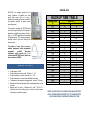
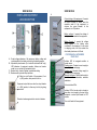
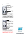
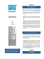
SIRE SM 4024 BRIEF INTRODUCTION ® SIRE is a registered trademark of the corporation Respaldo Inteligente S.A. de C.V which has being developing advanced electric systems of power conversion since 2000. SIRE offers a wide variety of solutions regarding alternate current (AC) and direct current (CC). USER MANUAL ® SIRE SM 4024 SIRE products include current inverters, battery chargers, power backup systems, load controllers, monitoring systems and battery control. SIRE products are smarter and more efficient than equipments of traditional power conversion. Our products are developed based on programmable microcontrollers than can be used in several applications, power backup systems for home, companies in case of power supply failures; mobile power systems on boats, commercial vehicles, heavy load trucks, emergency vehicles and automobiles. All our products are supported by an excellent infrastructure of aftersales service. ESSENTIAL TECHNICAL CONCEPTS An inverter is an independent power system that provides power in any time and any place due to the fact that it converts DC (Direct Current) power which is stored in batteries into AC (Alternate Current) for domestic use. A charging inverter is the one that switches two operation modes, usually the charging mode that automatically and in a clear way occurs when there is enough current power in our home, office or any other place; if power supply is missing (not enough current power), the charging loader switches in a clear way the inverter phase, thus keeping electric power in our home, office or any other place without switching being noticeable, that is to say, all appliances will continue working despite the outage. We recommend to read this manual before starting to use the equipment SIRE SM 4024 SIRE SM -4024 SIRE SM -4024 SM 4024 is a charging inverter that, at output, produces a modified sine wave signal (sine wave), that is to say, a waveform not exactly as the one provided by the domestic electrical an power system (pure sine wave). This waveform provided by SM 4024 does not provoke any side effect in the majority of appliances and lighting in general, that is to say, it is a 100% equipment recommended for lighting backup, PC's, cooling equipment, electrical motors and tools working with electric power. For backup of some kind of servers, medical equipment, audio professional equipment, certified laboratory equipment, switch boards, etc., it is recommended SPXXXX series, which are also a creation of SIRE®. GENERAL FEATURES Output power: 4 KVA. Output voltage in inverter mode: 120 volts + / - 5%. Output frequency in inverter mode: 60Hz + / - 5%. Output waveform in inverter mode: Modified sine wave. Transference time between charging mode - inverter: ?15 mseg. Backup time: See the following table, considering battery rack at full load. Battery rack: 24 volts in 4 batteries of 6 volts / 235 A C/U. (Supports up to three battery racks, in case you wish increase the quantity, contact the vendor). BACKUP TIME TABLE Equipment load (A) 2.00 3.00 4.00 5.00 6.00 7.00 8.00 9.00 10.00 11.00 12.00 13.00 14.00 15.00 16.00 17.00 18.00 19.00 20.00 21.00 22.00 23.00 24.00 25.00 Rack Life Hrs. 16 11 8 6 5 4 4 3 3 3 2 2 2 2 2 1 1 1 1 1 1 1 1 1 Minutes 39 6 19 40 33 45 10 42 20 2 46 34 23 13 5 58 51 45 40 35 31 27 23 20 THESE VALUES ARE CALCULATED FOR A SINGLE BATTERY RACK. THE EQUIPMENT SUPPORTS UP TO THREE BATTERY RACKS WHICH WOULD INCREASE THE BACKUP TIME SIRE SM 4024 PANELS AND EQUIPMENT LEDS DESCRIPTION SIRE SM 4024 A Output voltage of the equipment: It records the output voltage no matter what the operation mode of the equipment is, anytime the output Breaker of the equipment is in ON position. Battery voltage: It records the voltage of battery racks connected to the equipment. Battery Current: It records the voltage being supplied to the battery racks connected to the equipment, it only works in charging mode, until the moment the other battery banks are at full load. B A- Output voltage indicators of the equipment, battery voltage and current applied to the battery rack during the loading process. B- Adjustment potentiometer (for technical authorized staff only), LED indicators of equipment operation, failures and inverter mode, turn on and turn off equipment button. C- Breaker block, Inverter, Bypass, master/slave setting. D- Breakers with input and output switches. E- Main turn on/off switch of the equipment, if not in (ON) position, front panel will not run. Equipment output that runs when the output breaker is in (ON) position, it allows any kind of plug being connected. Protection breaker against short circuits in batteries. FOR TECHNICAL AUTHORIZED STAFF ONLY Indicator LED of energized condition in inverter mode: Flashing green: Constant current supply to the battery for its recharging. Flashing red: Constant voltage supply to the battery for its recharging. Alternate red/green: Floating load supply to the batteries for maintenance, maximum load status. Failure indicator LEDs. Indicator LED in Inverter mode is turned on when there is not supply to the input of the equipment or when Input Breaker in OFF position. Turn on/off switch of the equipment. SIRE SM 4024 C Inverter mode breaker: Turn on (ON): Equipment in normal operation position, it switches to inverter mode if there is power outage. Turn off (OFF): It turns power off at the output of the equipment even if there is supply at the input line. Bypass mode breaker: IF ACTIVATED, IT DISCONNECTS INVERTER BREAKER Turn on (ON): Disable operation mode as equipment inverter, it has at the output the same as at the input of the equipment, if there is a lack of supply, the output will also fail. This BYPASS breaker is used to activate the cancellation of the inverter in case the inverter fails and thus waiting for the technical and specialized staff to come. D Input breaker: Turn on (ON): Normal operation mode, the system acknowledges the actual status of the inverter supply; if there is power it will work in charging mode, if there is not power, the system will switch to inverter mode. Turn off (OFF): It is used to simulate an input outage. During this status, the equipment switch will go through inverter mode if the option is enabled in the respective breaker. Output breaker: Turn on (ON): It energizes the circuit connected to the output of the equipment. Turn off (OFF): Is turns power off at the output of the equipment. TO AVOID ELECTRICAL RISKS BY PERFORMING ANY ACTION WITHIN THE SUPPORTED CIRCUIT, PROCEED TO SWITCH THE OUTPUT BREAKER TO THE OFF POSITION.