1
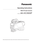
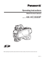
Operating Instructions Multi-Format Camera Model No. AK-HC3500P Before operating this product, please read the instructions carefully and save this manual for future use. VQTB0273-1 For your safety FCC Note: This equipment has been tested and found to comply with the limits for a class A digital device, pursuant to Part 15 of the FCC Rules. These limits are designed to provide reasonable protection against harmful interference when the equipment is operated in a commercial environment. This equipment generates, uses, and can radiate radio frequency energy, and if not installed and used in accordance with the instruction manual, may cause harmful interference to radio communications. Operation of this equipment in a residential area is likely to cause harmful interference in which case the user will be required to correct the interference at his own expense. CAUTION RISK OF ELECTRIC SHOCK DO NOT OPEN CAUTION: TO REDUCE THE RISK OF ELECTRIC SHOCK, DO NOT REMOVE COVER (OR BACK). NO USER SERVICEABLE PARTS INSIDE. REFER TO SERVICING TO QUALIFIED SERVICE PERSONNEL. The lightning flash with arrowhead symbol, within an equilateral triangle, is intended to alert the user to the presence of uninsulated “dangerous voltage” within the product’s enclosure that may be of sufficient magnitude to constitute a risk of electric shock to persons. Warning: To assure continued FCC emission limit compliance, the user must use only shielded interface cables when connecting to external units. Also, any unauthorized changes or modifications to this equipment could void the user’s authority to operate it. The exclamation point within an equilateral triangle is intended to alert the user to the presence of important operating and maintenance (service) instructions in the literature accompanying the appliance. For CANADA This class A digital apparatus complies with Canadian ICES-003. Cet appareil numérique de la classe A est conforme à la norme NMB-003 du Canada. CAUTION: Invisible Laser radiation is emitted from the Optical fiber connector when this product is turned on. Don’t look into directly into the Optical fiber connector of this product. WARNING: •TO REDUCE THE RISK OF FIRE OR SHOCK HAZARD, DO NOT EXPOSE THIS EQUIPMENT TO RAIN OR MOISTURE. CAUTION: This product uses a semiconductor laser system and is a laser class 1 product complies with Radiation Perfor mance Standards, 21CFR SUBCHAPTER J. Use of controls or adjustments or performance of procedures other than those specified herein may result in hazardous radiation exposure. Don’t make any modifications. Don’t repair by yourself. Refer servicing to qualified personnel. •TO REDUCE THE RISK OF FIRE OR SHOCK HAZARD, KEEP THIS EQUIPMENT AWAY FROM ALL LIQUIDS. USE AND STORE ONLY IN LOCATIONS WHICH ARE NOT EXPOSED TO THE RISK OF DRIPPING OR SPLASHING LIQUIDS, AND DO NOT PLACE ANY LIQUID CONTAINERS ON TOP OF THE EQUIPMENT. CAUTION: TO REDUCE THE RISK OF FIRE OR SHOCK HAZARD AND ANNOYING INTERFERENCE, USE THE RECOMMENDED ACCESSORIES ONLY. This product contains a CR Coin Cell Lithium Battery which contains Perchlorate Material — special handling may apply. See www.dtsc.ca.gov/hazardouswaste/perchlorate. indicates safety information. For your safety IMPORTANT SAFETY INSTRUCTIONS Read these operating instructions carefully before using the unit. Follow the safety instructions on the unit and the applicable safety instructions listed below. Keep these operating instructions handy for future reference. 1)Read these instructions. 10)Protect the power cord form being walked on or pinched particularly at plugs, convenience receptacles, and the point where they exit from the apparatus. 2)Keep these instructions. 3)Heed all warnings. 11)Only use attachments/accessories specified by the manufacturer. 4)Follow all instructions. 5)Do not use this apparatus near water. 12)Use only with the cart, stand, tripod, bracket, or table specified by the manufacturer, or sold with the apparatus. When a cart is used, use caution when moving the cart/apparatus combination to avoid injury from tip-over. 6)Clean only with dry cloth. 7)Do not block any ventilation openings. Install in accordance with the manufacturer’s instructions. 8)Do not install near any heat sources such as radiators, heat registers, stoves, or other apparatus (including amplifiers) that produce heat. 13)Unplug this apparatus during lightning storms or when unused for long periods of time. 9)Do not defeat the safety purpose of the polarized or grounding-type plug. A polarized plug has two blades with one wider than the other. A groundingtype plug has two blades and a third grounding prong. The wide blade or the third prong are provided for your safety. If the provided plug does not fit into your outlet, consult an electrician for replacement of the obsolete outlet. 14)Refer all servicing to qualified service personnel. Servicing is required when the apparatus has been damaged in any way, such as power-supply cord or plug is damaged, liquid has been spilled or objects have fallen into the apparatus, the apparatus has been exposed to rain or moisture, does not operate normally, or has been dropped. Contents For your safety . ......................................................... 2 System connections 1 (with Multi-Format Camera) . .. 20 Overview ................................................................... 4 System connections 2 (with Buildup Unit) . ................ 21 Accessories ............................................................... 4 System connections 3 (with MSU) . ........................... 22 Features .................................................................... 4 Status displays on viewfinder screen ...................... 23 Precautions for use . .................................................. 5 Checking and setting the calendar .......................... 24 Controls and their functions . ..................................... 6 Camera warning displays ........................................ 24 Mounting the lens .................................................... 12 Menu operations . .................................................... 25 Adjusting the lens flange back . ............................... 13 Setting menu configuration . .................................... 27 Performing the viewfinder adjustments ................... 14 Table of adjustment setting ranges . ........................ 32 Connecting a microphone ....................................... 16 SD memory card operations . .................................. 39 Mounting the camera on a tripod . ........................... 17 AK-HC3500 connector pin assignment ................... 40 Component system configuration ............................ 18 External dimension drawings .................................. 41 Specifications .......................................................... 42 Overview This unit is a new-generation multi-format HD camera that supports the 1080i format. It uses a new-generation 2/3-inch 2.2-megapixel IT-CCD [1920 (H) 1080 (V)] imaging device. This newly developed CCD employs leading-edge processes and embodies a fresh look taken at the on-chip lens and CCD structure to improve the sensitivity, smear and dynamic range by a significant margin over previous CCDs. Furthermore, Panasonic’s horizontal single-line readout CCD and high‑precision signal processing combine to achieve pixel shifting and a dramatic reduction in moire within the band. Another salient feature is the newly developed digital signal processor LSI chip which is mounted in the camera head and supports 14-bit A/D conversion: This chip processes the gamma, knee, detail, matrix and other process signals, delivers the kind of multi-functionality, high quality and high stability that digital technology alone can provide, and improves the operating ease. The 14-bit A/D converter is instrumental in creating a stable wide dynamic circuit with a high signal-to-noise ratio from the dark area all the way to the highlights. Using the dynamic range stretch (DRS) function which adjusts the gamma correction optimally in real time, both the dark areas and light areas can now be reproduced with startling clarity. The camera head with its new design features an overall smaller size and lower profile that neatly taken into consideration the performance of buildup operations, and the fact that it is now possible to connect it with the buildup unit without the need to hook up any cables has resulted in a significant improvement in both operability and applicability. The amount of heat generated by the camera has also been slashed as a result of adopting a low-power-consumption design for the new circuits and a heat-dissipation design for the new chassis. When this Multi-Format Camera is connected to a CCU (AK‑HCU931, optional accessory), not only can HD signals be input and output but SD signals (D1, VBS) can be output and RET/PROMPT signals can be input as well. The iris, pedestal, gain and other camera adjustments can be carried out by remote control using a unit such as the ROP (AK-HRP931) or MSU (AK-MSU935) available as optional accessories. Accessories Operating Instructions ......................................................... 1 Camera No. plate (1 to 12) ............................................ 1 set Camera hangers* ................................................................ 2 Screws* (M3 8 mm) ......................................................... 4 Mount cap . .......................................................................... 1 * These accessory parts are used when mounting the buildup unit (AK-HBU3500). Keep them in a safe place to ensure that you will not lose or misplace them. Features Newly developed 1080I, 2.2 million-pixel CCDs incorporated Standard sensitivity of F10 and high sensitivity on a par with SD. Smear has been cut to approx. 130 dB and the number of white marks has been drastically reduced by process improvements. H‑CCD drive is accomplished at a frequency of 74 MHz to attain a high response and high resolution. Designed to achieve low noise levels of below NC15 Power consumption can be reduced since the fan mode can be switched according to the situation in which the camera system is being applied. As a result, the heat‑dissipation design has also been optimized. Fuller complement of control circuits and auto setup (ASU) function Users can select the standard mode or simplified mode. Digital signal processing LSI with high picture quality featured in the camera unit After the process circuits, the signals undergo 14‑bit, 74 MHz high-picture-quality digital processing, yielding a high reliability, more functions and enhanced operating ease as a result. Peripheral components Ease of operation can be further improved by configuring a system where the Multi-Format Camera is used in combination with the remote operation panel (ROP) and master setup unit (MSU). Data trunk function Two RS-422 and two RS-232C circuits are provided as a standard feature. They obviate the need for the cables used with virtual control, pan-tilt head and lens control, etc. Multi-functional enhancer In addition to the many functions such as skin DTL, there is a choice of 30 boost frequencies. Precautions for use DON’TS DO’S Do not attempt to disassemble the camera or other units. In order to prevent electric shock, do not remove screws or covers. There are no user-serviceable parts inside. Refer any servicing to qualified service personnel. Do not abuse the camera. Avoid striking, shaking, etc. The camera contains sensitive components which could be damaged by improper handling or storage. Protect the precision made lens by placing the lens cap over when the camera is not in use. If the lens is not installed, protect the surface of the prism by placing the body cap into the lens mount hole. Handle the camera with care. Do not let the lens remain uncapped when the camera is not use. If the lens is not installed, do not leave the lens mount hole uncovered. Use a mild blower or lens cleaning tissue designed for coated lenses, to clean the surface of the lens or prism in the event that it should become dirty. Do not touch the surface of the lens or prism. Use a dry cloth to clean the camera if it is dirty. In case the dirt is hard to remove, use mild detergent and wipe gently. Do not use strong of abrasive detergents when cleaning the camera body. Do not aim the camera toward the sun, no matter whether it is turned on or not. Taking images of sunlight and other such conditions for prolonged periods of time may damage the CCD. Use caution when operating the camera in the vicinity of spot lights or bright lights, as well as light reflecting objects and surfaces. Take immediate action if ever the camera should become wet. Turn the power off and have the unit checked by an authorized service facility. Do not operate the camera outdoors during a lightning storm. Do not use the camera in an extreme environment where high temperatures or high humidity exist. Follow normal safety precaution to avoid personal injury. Use the camera in an environment where the temperature is within 14 °F to +113 °F (–10 °C to +45 °C), and the relative humidity is less than 85 % (no condensation). Do not leave the camera turned on when not in use. Do not unnecessarily turn the camera power on and off repeatedly. Do not block the ventilation slots. Always turn the power off when the camera is not going to be used. Operate the camera only when there is adequate ventilation. Do not cover the port otherwise block ventilation during operation. Internal heat buildup can cause a fire. Cooling fan There is internally provided a cooling fan. Since the cooling fan is a consumable part, replace it after about 50,000 hours of operation. (Be sure to ask the dealer for the replacement.) When using the unit in windy or snowy conditions or at the beach or at the waterfront, cover it with the rain cover (optional accessory) or protect it in some other way in order to prevent it from getting wet and stop water from seeping inside. Use the camera in places with minimal moisture and dust. Avoid using the camera in places with high concentrations of moisture or dust since these conditions will tend to cause damage to the internal parts. In addition, ensure that the connectors which are not in use are covered with their protective caps. Peripheral equipment software The versions of the software used for the peripheral units (such as the CCU, ROP and MSU) connected to the AK‑HC3500 may need to be updated. For further details, contact your dealer. Controls and their functions Controls and their functions Controls and their functions Camera power switch [POWER] Lens mount (Bayonet type) This is used to select the camera power input (power supplied from the CCU or from an external connector) and turn the power ON and OFF. This is where the lens is mounted. Lens clamp lever The lens is inserted into the lens mount , and this lever is then turned to clamp the lens in place. Power LED This lights up green when power is supplied to the camera. When the camera’s power switch is set to OFF, this lights up red if the CCU is connected, and it goes off if the CCU is not connected (if the power was turned ON by the CCU). Lens cable, mic cable clamps These are used to clamp the lens cable and mic cable in place. DCamera hangers (supplied) When the buildup unit (AK-HBU3500) is used, install these hangers to the camera with supplied screws (M3 8 mm). For details, refer to the Operating Instructions for AK‑HBU3500. Power circuit breaker [BREAKER] This shuts off the power in the event of an overcurrent while the DC 12 V power supply is used. To reset the circuit breaker, eliminate what caused it to trip, and then press the circuit breaker button. ETripod mount INCOM connectors 1, 2 [INCOM1, INCOM2] Before securing the Multi-Format Camera to a tripod, attach the tripod adapter (SHAN-TM700) which is available as an optional accessory. The INCOM or headset plugs are connected here. INCOM1 MIC ON/OFF switch [MIC1 TALK] This is the INCOM1 MIC ON/OFF selector switch. FShoulder pad This is used when the Multi-Format Camera is to be carried on the shoulder. It can be adjusted to position it more toward the front or more toward the back. INCOM1 level control [INCOM1 LEVEL] This is used to adjust the INCOM1 receiving volume level. INCOM2 MIC ON/OFF switch [MIC2 TALK] GSlide lock release lever This is the INCOM2 MIC ON/OFF selector switch. This is held down while it is used to adjust the front/back position of the shoulder pad F. Use it to adjust the position of the shoulder pad so that the camera can be operated more easily while it is being carried on the shoulder. INCOM2 level control [INCOM2 LEVEL] This is used to adjust the INCOM2 receiving volume level. 9INCOM1 PGM1 level control [INCOM1 PGM1] This is used to adjust the INCOM1 and PGM1 mixing level. HShoulder strap fitting This enables the shoulder belt to be attached. INCOM1 PGM2 level control [INCOM1 PGM2] IOptical cable clamp This is used to adjust the INCOM1 and PGM2 mixing level. This enables the optical cable to be clamped. JCamera No. plate holder INCOM2 PGM1 level control [INCOM2 PGM1] This enables the accessory camera No. plate to be attached. This is used to adjust the INCOM2 and PGM1 mixing level. KOptical fiber connector (EDW.3K made by LEMO) INCOM2 PGM2 level control [INCOM2 PGM2] This is used to adjust the INCOM2 and PGM2 mixing level. This is used to connect with the CCU (camera control unit) using the optical fiber cable. When it is not in use, cover it with its protective cap. Controls and their functions RET-A selector switch [RET A] Camera HD-SDI output1 connector (BNC) [HD-SDI1] This switch is used to select the return images to be switched by RET-A. The return images which have been set on the ROP menu are allocated to this switch. The camera HD-SDI images are output from this connector. Camera HD-SDI output2 connector (BNC) [HD-SDI2] RET-B selector switch [RET B] This switch is used to select the return images to be switched by RET-B. The return images which have been set on the ROP menu are allocated to this switch. Camera images, VF images or RET images can be selected on the camera menu to output HD-SDI signals from this connector. Optional video connector (BNC) [AUX] CALL LED This is an auxiliary input/output connector. The HD analog Y input or Prompt2 output (when the CCU has a Prompt2 input) can be selected. When a down-converter (optional accessory) has been installed in the camera, this connector can be used as a VBS or D1 output connector. This lights up green when the CALL switch is pressed from the ROP, MSU or CCU. CALL switch [CALL] This lights the CALL LED on the ROP or MSU and sounds the buzzer (when ON has been selected as the buzzer setting). Genlock sync input/PROMPT output connector [PROMPT/GL] OPT LED When the GL/PROMPT selector switch is set to GL, the reference signal (tri-level SYNC or B.B.) which is used to genlock the camera is input to this connector; Genlock sync signals are input to this connector when the CCU is not connected. When it is set to Prompt, the Prompt images input from the CCU are output from this connector. This indicates the camera’s optical signal reception status. It normally lights up green. When any problem has occurred, it lights up red. When a problem has occurred, clean the optical fiber connector. If the problem is not cleared up, immediately turn off the power, and contact your dealer. GL/PROMPT selector switch Back tally LED selector switch This is used to select the genlock input or the input/output (genlock input and PROMPT output) signals of the PROMPT output connector. This is used to set the back tally LED to ON or OFF. Back tally LED This lights when the tally signal is supplied. This lights up red when the R tally signal is supplied, green when the G tally signal is supplied, and red when both the R and G tally signals are supplied. Remote connector [REMOTE] The remote operation panel (ROP, optional accessory) is connected to this connector. The [SYSTEM], [FUNC] and [SD DTL] menus of the ROP cannot be controlled. Neither can the [HEAD POWER], [CHARA], [BAR], [MONO], [SD DTL OFF] and [MONITOR (R/G/B/SEQ/ ENC)] switches be controlled. RET switching control connector [RET CONT] The cable of the RET switching box (optional accessory) is connected here for controlling the ON/OFF of RET1, 2, 3 and INCOM1, 2 MIC. External power supply input connector [DC IN] External I/O [EXT I/O] The input of the external DC power supply is connected to this connector. (DC 10.8 V to 17 V) This signal interface connector is designed to support future interfacing with external devices. MIC1 selector switch [LINE/FRONT MIC/MIC] This is used to switch the input signal to LINE, FRONT MIC or rear MIC. Controls and their functions Rear MIC1 connector [MIC1] Filter local LED [LOCAL] An audio component or microphone is connected to this connector. The gain setting can be selected on the camera menu. While this LED is lighted, the optical filter can be adjusted manually. Monitor output selector switch [MONI SEL] Rear MIC2 connector [MIC2] This is used to select the viewfinder image and the HD SDI2 image (Y, NAM, R, G, B) in the VF OUT status. An audio component or microphone is connected to this connector. The gain setting can be selected on the camera menu. ND filter selector knob This is used to adjust the optical filter manually when LOCAL has been selected as the filter setting. DC output connector [DC OUT] The R or G tally signal is output from this connector (open collector). A DC 12 V power supply (up to 1.0 A) can also be supplied. If the current exceeds the rating, the power is turned off forcibly. 1: CAP, 2: Through, 3: 1/4, 4: 1/16, 5: 1/64 Do not turn this knob while the filter local LED is off. CC filter selector knob This is used to adjust the optical filter manually when LOCAL has been selected as the filter setting. Earphone jack [EARPHONE] A: 3200K, B: 4300K, C: 6300K, D: Cross, E: DF0 When an earphone (optional accessory) is connected to this jack, the INCOM1 receiving signals can be heard. Do not turn this knob while the filter local LED is off. Data trunk connector [TRUNK] Gain selector switch [GAIN] The trunk data [RS-422 2 or RS-232C 2] of the CCU is input to and output from this connector. The camera menu is used to select the setting. This is used to select the gain for the camera images. (LOW, MID, HIGH) It is not effective when the CCU is connected to the camera. The gain setting can be selected on the camera menu. MIC1 power selector switch This is used to select what kind of power is to be supplied to MIC1. (The switch is set to phantom 48 V, AB 12 V or OFF.) Camera output selector switch [OUTPUT] This is used to select the video output (CAM, BAR or TEST). It is not effective when the CCU is connected to the camera. MIC2 power selector switch This is used to select what kind of power is to be supplied to MIC2. (The switch is set to phantom 48 V, AB 12 V or OFF.) White balance memory selector switch [W.BAL] This is used to select the white balance memory. Data can be recorded in A or B. The factory settings are established when the switch is set to PRST. It is not effective when the CCU is connected to the camera. Grip PTT switch [PTT] This selector switch is used to set the INCOM1 MIC to ON or OFF. The camera menu is used to select the setting. Grip RET switch [RET] Assignable switch [USER 1, 2, 3] This is used as return image selector switch. The camera menu is used to select the setting. The ON/OFF function settings established ahead of time can be allocated to these switches using the camera menu. Optical filter selector switch [FILTER LOCAL] When this switch is pressed and the filter local LED lights, the optical filter can be adjusted manually. When it is pressed again, the optical filter can be controlled by the ROP. 10 Controls and their functions SD memory card connector [SD CARD] VF connector [VF] The SD memory card (optional accessory) is inserted here. For the recording items, refer to the “Table of the adjustment setting ranges”. (See pages 32 to 33.) The 2˝ viewfinder cable is connected to this connector. Rear VF connector This D-sub connector is used for Viewfinder interface. Back light switch [LIGHT] SD memory cards whose operation has been authenticated (recommended) Cards made by Panasonic with a memory size of 2 GB or less (SD-HC memory cards are not supported) This light switch is used to make it easier to read the characters on the camera’s back panel. The brightness can be adjusted using the camera menu. SD Logo is a trademark. MIC1 Talk LED [TALK] This LED lights up green when the INCOM1 MIC is operational. It blinks when the MIC has been forcibly set to OFF by a remote control operation. Menu switch [MENU] When this switch is pressed, the camera’s user menu is output; when it is pressed again, the menu screen display is cleared. MIC2 Talk LED [TALK] JOG dial button This LED lights up green when the INCOM2 MIC is operational. It blinks when the MIC has been forcibly set to OFF by a remote control operation. Turning the JOG dial while the menu screen is displayed moves the cursor to the setting items. The menu settings are established by operating this dial button. For details on the menu operations, refer to the section on the menu operations. MIC2 selector switch [LINE/MIC] This switch is used to select LINE or MIC for the input signals. Electronic shutter selector switch [SHUTTER] This is set to ON when the electronic shutter is to be used. When it is set to the SEL position, the shutter speed is switched in the preset range. It is not effective when the CCU is connected to the camera. Buildup unit I/F This signal interface connector is used to connect the Buildup unit. Tally output connector [TALLY OUT] AWB/ABB start switch [AUTO W/B BAL] The R or G tally signal is output from this connector (open collector). A DC 12 V power supply (up to 1.0 A) can also be supplied. If the current exceeds the rating, the power is turned off forcibly. This is used for conducting automatic white balance adjustments (AWB) or automatic black balance adjustments (ABB). It is not effective when the CCU is connected to the camera. Lens connector [LENS] The lens cable is connected to this connector. Front MIC1 connector [MIC1] A microphone (optional accessory) is connected here. When using the microphone, set the MIC1 selector switch to front MIC. (See page 16.) The power supply for the microphone can be connected from this connector. What kind power is to be supplied is set using the MIC1 power selector switch. 11 Mounting the lens 1 4Insert the cable into the cable clamp and connect it to Raise the lens clamp lever, and remove the mount cap. the lens connector. Lens connector Mount cap Lens clamp lever Notes For details on handling the lens, refer to the instructions that accompany the lens. Depending on the lens mounted, it may be necessary to perform the following lens and camera adjustments. 1.Flange back adjustment for the lens 2.Auto iris operation speed adjustment for the lens 3.White shading adjustment for the lens (performed using the controls on the camera) 2Align the guide pin on the lens with the groove at the top center of the lens mount, and mount the lens. Groove Guide pin 3 Lower the lens clamp lever to clamp the lens in place. Lens clamp lever 12 Adjusting the lens flange back Adjust the flange back (distance from the surface where the lens is mounted to the surface where the images are formed) if the subject fails to be precisely focused at both the telephoto and wide-angle settings when zoom operations are to be performed. Once adjusted, the flange back does not need to be adjusted again unless the lens is replaced. Adjustment method Note For details on the adjustment method and positions of the lens parts, refer also to the instructions that accompany the lens. About 9.9 ft. (3 m) 1Mount the lens on the camera. Do not forget to connect 5Set the zoom ring to the telephoto position either by 2Set the lens iris to manual, and open the iris. 6Shoot the flange back adjustment chart, and turn the the lens cable at this time. manual or electrical means. distance ring to adjust the focus. 3Set the lighting in such a way that the appropriate video 7Set the zoom ring to the wide-angle position, and turn output level is obtained at a distance of about 9.9 ft. (3 m) from the flange back adjustment chart. If the video level is too high, use a filter or shutter. the F.f ring to adjust the focus. Take care not to move the distance ring. 4Loosen the screw that secures the F.f (flange focus) 8Repeat steps 5 to 7 until the chart is focused properly ring. at both the telephoto and wide-angle positions. Note 9Tighten up the screw that secures the F.f ring. Depending on the lens concerned, this ring may be marked as the “F.b” (flange back) ring. 13 Performing the viewfinder adjustments (The viewfinder is an optional accessory.) Attaching the viewfinder Detaching the viewfinder 1Check that the camera’s POWER switch is at the OFF 1Check that the camera’s POWER switch is at the OFF 2Pull up the knob on the mounting plate and slide the 2Loosen the stopper screw, pull up the knob on the position. position. plate to attach the viewfinder. mounting plate and slide the viewfinder along and off the plate. Pull up the knob Stopper screw Pull up the knob 3 Tighten the stopper screw securely. Stopper screw 3 4 Connect the plug to the VF connector. Note When connecting the plug to the VF connector, ensure that it is fully and securely inserted. 14 Disconnect the plug from the VF connector. Performing the viewfinder adjustments (The viewfinder is an optional accessory.) Left or right position adjustment 1 Forward or backward position adjustment Loosen the stopper screw. 1Rotate the viewfinder forward/backward position fixing Stopper screw lever towards the outside to release it from the locked position. Viewfinder forward/backward position fixing lever Viewfinder Viewfinder 2Move the viewfinder to the left or right to adjust its position. 2Move the viewfinder forward or backward to adjust its position. 3 Tighten the stopper screw. Stopper screw 3Rotate the viewfinder forward/backward position fixing lever in the opposite direction until it locks. Viewfinder forward/backward position fixing lever 15 Connecting a microphone When the microphone is mounted on the viewfinder (optional accessory) for use A microphone such as the AJ-MC700 microphone kit (optional accessory) can be mounted on the viewfinder. 1 4If the audio channel whose signals are to be recorded Open the microphone holder. so requires, set the MIC1 selector switch to FRONT MIC. Microphone holder 2 MIC1 selector switch Mount the microphone and tighten up the clamp screw. Clamp screw 3Connect the microphone cable to the front MIC1 connector on the camera. Front MIC1 connector 16 Mounting the camera on a tripod Use the tripod attachment, available as an optional accessory, to mount the camera on a tripod. 1 Detaching the camera from the tripod attachment While pushing the red lever, move the black lever in the direction of the arrow, and slide the camera toward the back. Mount the tripod attachment on the tripod. Tripod attachment Note Select the appropriate holes from among the holes on the bottom of tripod attachment depending on where the center of gravity of the camera and tripod attachment falls. If the holes selected are not appropriate, the center of gravity will not be supported, as a result of which the camera may drop off or fall over, which in turn may possibly cause injury. Check that the diameter of the holes selected for mounting matches the diameter of the screw holes of the tripod platform. If these diameters do not correspond, the tripod attachment will not be secured properly, as a result of which the camera may drop off or fall over, which in turn may possibly cause injury. Red lever Black lever <Note> If the pin of the tripod attachment fails to return to its original position after the camera has been detached, push the red lever again and simultaneously move the black lever in the direction of the arrow to return the pin to its original position. Bear in mind that the camera cannot be mounted if the pin still remains at the center. Tripod attachment Note Concerning the steps for ensuring that the camera does not slip or drop out of position When installing the camera on a crane or at some other position high above the floor or ground, first check that the crane can bear the weight of the entire system including the camera, lens and connecting cables, and then use the specified tools to install the camera securely. Be absolutely sure to ensure that the camera will not drop from its position by looping an anti-drop wire around its handle and securing the end of the wire at a point above the camera, as shown in the figure below. Tripod platform 2Mount the camera on the tripod attachment. Slide the camera toward the front along the groove until a click is heard. Now check that the camera is secured properly. Anti-drop wire 17 Component system configuration An example of the standard system consisting of the Multi-Format Camera (AK-HC3500) and peripheral components is described below and shown on the following page. The MSU (AK-MSU935) is not required unless a multiple number of cameras are to be controlled. The basic system configuration includes the lens, Multi-Format Camera, viewfinder, camera control unit (CCU) and remote operation panel (ROP). System block diagram Large lens Master Setup Unit AK-MSU935 Buildup Unit AK-HBU3500 Camera Control Unit AK-HCU931 Microphone Kit AJ-MC700 8˝ LCD Viewfinder AK-HVF931A ROP cable 2˝ Electronic HD Viewfinder AJ-HVF21 Multi-Format Camera AK-HC3500 Handy lens Remote Operation Panel AK-HRP931 SD memory card Tripod Attachment SHAN-TM700 18 Component system configuration Outline of peripheral components Component connections Camera Control Unit (CCU: AK-HCU931) Refer to pages 20 to 22 for the component connections. After all the components have been connected (the monitor system may be connected afterward), set the CCU’s main power switch to the ON position. Then turn on the camera’s power switch. This is the Multi-Format Camera’s camera control unit. It is connected to the Multi-Format Camera using an optical fiber cable. HD/SD video input and output can be supported by inserting the HD/SD output unit. Remote Operation Panel (ROP: AK-HRP931) The ROP is connected to the CCU using the ROP cable, and enables the camera, CCU and lens to be operated by remote control. Master Setup Unit (MSU: AK-MSU935) When a multiple number of cameras and CCUs are used, the MSU can operate up to 12 units either separately or simultaneously by remote control. It can be operated together with the ROP. 2˝ Electronic HD Viewfinder (2˝ VF: AJ-HVF21) This is the viewfinder for the Multi-Format Camera. 8˝ LCD Viewfinder (8˝ LCD VF: AK-HVF931A) This is the LCD viewfinder for the Multi-Format Camera. It can be used at the same time as the 2˝ viewfinder. It can still be operated when the system is built up. Buildup Unit (AK-HBU3500) A large-sized lens can be mounted on the multi‑format camera to enable the same operations as for a large‑sized camera can be undertaken. 19 System connections 1 (with Multi-Format Camera) 2˝ Electronic HD Viewfinder AJ-HVF21 Optical cable Camera Control Unit AK-HCU931 Lens Multi-Format Camera AK-HC3500 ROP cable Remote Operation Panel AK-HRP931 Before proceeding with the connections, set the CCU power switch to the OFF position. Connect the optical cable to the Multi-Format Camera and CCU. Connect the ROP cable to the CCU and ROP. When the camera power switch is set to ON after the CCU main power switch has been set to ON, the camera can be controlled using the ROP. Upon completion of shooting, set the CCU camera power switch and main power switch to OFF. 20 System connections 2 (with Buildup Unit) Large lens Buildup Unit AK-HBU3500 8 LCD Viewfinder AK-HVF931A Optical cable Camera Control Unit AK-HCU931 Multi-Format Camera AK-HC3500 ROP cable Remote Operation Panel AK-HRP931 21 System connections 3 (with MSU) Master Setup Unit AK-MSU935 Optical cable Camera Control Unit 1 AK-HCU931 Multi-Format Camera 1 AK-HC3500 Remote Operation Panel 1 AK-HRP931 Optical cable Camera Control Unit 11 AK-HCU931 Multi-Format Camera 11 AK-HC3500 Remote Operation Panel 11 AK-HRP931 Optical cable Multi-Format Camera 12 AK-HC3500 Camera Control Unit 12 AK-HCU931 Remote Operation Panel 12 AK-HRP931 Large lens Buildup Unit AK-HBU3500 A multiple number of cameras (up to 12 units) can be controlled in one location using the MSU. The cameras can be controlled by both the ROPs and MSU. 22 Status displays on viewfinder screen Filter display: This indicates the type of filter selected. Besides the images, Multi-Format Camera settings and messages indicating operating statuses appear on the viewfinder screen. The camera menu VF DISPLAY screen and the items which have been set to ON using the switches related to the viewfinder display appear at the top and bottom of the screen. When a setting has been changed or an adjustment made, a message with details of the setting, the status of the adjustment process or the adjustment result can be displayed for about 3 seconds. White balance memory display: This indicates the automatic adjustment memory selected for the white balance. A: The WHITE BAL switch is set to “A”. B: The WHITE BAL switch is set to “B”. P: The WHITE BAL switch is set to “PRST”. Gain display: This indicates the video amplifier’s gain setting (in dB) which has been selected by the gain selector switch. Display items and where the items appear Audio CH1 and CH2 displays: The audio levels are displayed here (separately for audio CH1 and audio CH2). Extender display Shutter speed/mode display RET SEL display Voltage display Filter display White balance memory display Gain display Audio CH1 and CH2 displays Iris f-number display Camera warning or message display Focus position display Zoom position display MONI SEL display Optical level display 5600K display Field frequency display Iris f-number display: The approximate value of the iris setting (f-number) is displayed here. <Note> This display appears when a lens which has an f-number output is being used. Camera warning or message display: A message indicating the occurrence of an error, the camera settings, the progress made in the adjustments, and the adjustment results appear here for about 3 seconds. Focus position display: The focus position is indicated here in the form of a number. <Note> This display appears only when a lens which has a focus position output is being used. Zoom position display: The zoom position is indicated here in the form of a number. <Note> This display appears only when a lens which has a zoom position output is being used. MONI SEL display: This indicates the video mode of the monitor output. Optical level display: This indicates the light sensing level of the optical fiber cable. Extender display: This appears when the lens extender is being used. Shutter speed/mode display: This indicates the shutter speed or shutter mode setting. 5600K display: This indicates the setting of the electronic color compensation. RET SEL display: This indicates the return mode selected by the RET switch. Field frequency display: This indicates the field frequency at which the camera is operating. Either 50i or 59.94i is displayed. Voltage display: This indicates the voltage of the DC IN currently in use. 23 Checking and setting the calendar The calendar is checked and set on the [Date/Time] page located on the Maintenance menu. Checking the current settings 1. Check the current year/month/day, day of the week and time displayed on [Present]. 2. Select [Adjust], press the jog dial, and when [YES?] is selected and entered, the seconds are reset to “00.” Adjusting the time 1. At [12H/24H], select whether the 12-hour or 24-hour system is going to be used. 2. At [Date], set the year, month, day and day of the week. 3. At [Time], set the hours, minutes and seconds. 4.At [Set Exe], when [YES?] is selected and entered, the adjusted year/month/day, day of the week and time are displayed in [Present]. 5. At [Reset], when [YES?] is selected and entered, the following is displayed: 00/01/01 MON 00:00:00 Notes The calendar function will not operate properly when an irregular year/month/day, day of the week or time is set. The manufacturer disclaims all responsibility for any trouble which may be caused by the calendar function. Camera warning displays Warning displays appear when errors have occurred in the camera’s auto functions. Set [Status (AUTO)] to ON at [VF Display2] under [Operation]. When AWB is executed: 1 AWB LOW LIGHT Auto white balance cannot be executed because the light quantity is insufficient. Set the light quantity to the appropriate level. 2 AWB HIGH LIGHT Auto white balance cannot be executed because the light quantity is excessive. Set the light quantity to the appropriate level. 3 AWB R/Bch NG Out Range The white balance convergence for the red or blue channel cannot be achieved. Shoot a uniformly white object on the screen, and execute AWB. When ABB is executed: 1 Not Finished Auto black balance cannot be completed successfully. The lens iris may not be open or the ND filter may not be set to CAP. 2 R/B Out Range The black balance convergence for the red or blue channel cannot be achieved. Check whether there are any abnormalities in the image. When ASU is executed: 1 LENS CTL NG Out Range The lens iris cannot be controlled. Review the lens settings. 2 --- R/Bch NG Trouble has occurred in the red or blue channel in the process which is being executed. Using a regular chart, check the correct position vis-à-vis the chart and angle of view, check the color temperature setting of the light source, and check whether any other areas are not amenable to control. 24 Menu operations Entering the menu data Basic setting menu operations After accessing the item menus, enter the respective data. Displaying the menus 1Turn the JOG dial to select the menu item to be set. User menu 1Press the MENU switch. The camera’s USER menu screen now appears on the viewfinder or monitor. 2When the JOG dial is pressed, the setting of the item indicated by the arrow flashes. 2 Turn the JOG dial to select the menu item. 3After having selected the item, press the JOG dial to access that item’s menu. 3 Turn the JOG dial to change the setting. 4 When the JOG dial is pressed, the data is entered. Note Bear in mind that if, in step 3, the MENU switch is set to OFF while the setting is flashing, the setting prior to the flashing will remain unchanged. 25 Menu operations Entering the menu data (continued) When the setting flashes one character at a time, press the JOG dial to move the flashing toward the right. 1When the JOG dial is pressed, flashing moves toward the right. 2 Turn the JOG dial to change the setting. 3 When the JOG dial is now pressed, the data is entered. 26 Setting menu configuration Hierarchical menus USER MENU 27 Setting menu configuration Hierarchical menus USER MENU 28 Setting menu configuration Hierarchical menus USER MENU 29 Setting menu configuration Hierarchical menus USER MENU 30 Setting menu configuration Hierarchical menus USER MENU 31 Table of adjustment setting ranges Operation Menu VF Setting1 VF Setting2 Item Side Modu SW OFF, ON OFF Side Modu LVL 0 to 31 31 Zone Mark OFF, 4:3, 13:9, 14:9, 15:9, 16:9 OFF Safety Mark1 Safety Area1 Safety Mark2 Safety Area2 Center Mark Center Mark SEL Line Width Marker Level VF DTL 16:9, 15:9, 14:9, 13:9, 4:3, OFF 80 %, 90 %, 93 %, 100 % 16:9, 15:9, 14:9, 13:9, 4:3, OFF 80 %, 90 %, 93 %, 100 % OFF, ON 1 to 4 1 to 3 100 %, 75 %, 50 % 0 to 23 12.4M, 12.5M, 12.7M, 12.9M, 13.0M, 13.3M, 13.6M, 13.9M, 14.2M, 14.6M, 15.0M, 15.5M, 16.1M, 16.7M, 17.3M, 18.0M, 18.6M, 18.8M, 19.0M, 19.2M, 19.5M, 19.9M, 20.3M, 20.9M, 21.5M, 22.4M, 23.6M, 25.4M, 28.6M, 37.1M 0 to 5 0 to 63 2.0M, 2.3M, 2.7M, 3.4M, 4.5M, 6.8M, 13M 0 to 5 0 to 63 2.0M, 2.3M, 2.7M, 3.4M, 4.5M, 6.8M, 13M 0 to 5 0 to 63 OFF, ON ADJ, 1, 2, 1+2 0 to 255 0 to 255 0 to 255 0 to 255 BOX, CROSS MEM1, MEM2 NO?, YES? OFF, ON OFF, ON OFF, ON OFF, ON OFF, ON OFF, ON OFF, ON OFF, ON OFF, ON OFF, ON OFF, ON OFF, ON OFF, ON OFF, ON OFF, ON OFF, ON OFF, ON OFF, ON OFF, ON, AUTO LOW, NORM OFF, ON OFF, ON — OFF 93 % OFF 80 % OFF 1 2 100 % 10 Items recorded on SD memory cards No switching from the SD memory card to the camera settings possible while the buildup unit is connected. No switching from the SD memory card to the camera settings possible while the buildup unit is connected. No switching from the SD memory card to the camera settings possible while the buildup unit is connected. 12.4M 0 0 6.8M 0 0 6.8M 0 0 OFF ADJ 127 127 127 127 BOX MEM1 NO? OFF OFF OFF OFF OFF OFF OFF OFF OFF OFF OFF OFF OFF OFF OFF OFF OFF OFF ON NORM OFF OFF — HD Peak FREQ Cursor VF Display1 VF Display2 Setting1 HD Offset Gain HD Crisp D1 Peak FREQ D1 Offset Gain D1 Crisp VBS Peak FREQ VBS Offset Gain VBS Crisp Cursor Cursor Memory H Position V Position Width Height BOX/CROSS Store Memory EXECUTE F Number Zoom Focus Extender MONI OUT Filter M Gain Shutter 5600K Audio Level OPT Level RET Select Status Status(AUTO) Field Rate Voltage WFM (*1) White CH FAN Power FAN Mode CALL+R_TALLY CALL+T_TALLY PinP Mode Adjustment setting range Initial value *1: W aveforms are displayed as a single line at the center of the screen. They appear at the bottom right when the aspect ratio is set to 16:9, but when an aspect ratio of 4:3 is set on the viewfinder or when the side panel mode is selected by the down-converter, the waveform display will be cut off in part. 32 Table of adjustment setting ranges Menu Setting1 Setting2 Setting3 Setting4 !LED 7"VF INCOM Set.1 INCOM Set.2 MIC Gain Item HD-SDI2 OUT HD-SDI2 Power AUX I/O TRUNK1 TRUNK2 5600K HND GRIP RET HND GRIP PTT HND Lens VTR HND Lens RET STD Lens RET1 STD Lens RET2 EXT RET 1 EXT RET 2 EXT RET 3 RET1 ID RET2 ID RET3 ID RET4 ID Gain SW LOW Gain SW MID Gain SW HIGH ID Character User SW1 User SW2 User SW3 User B/U Back Light RET Mode Lens I/F B/U Lens Rear ROP VR Gamma Off Shutter Extender MONI OUT FAN Off Master Gain Black Gamma VF FAN Speed Peak Slice Peak FREQ INC1 MIC Type INC1 MIC Gain INC1 MIC Power INC1 Side Tone INC1 PGM MIX INC1 ENG/PROD INC1 to CCU INC2 MIC Type INC2 MIC Gain INC2 MIC Power INC2 Side Tone INC2 PGM MIX INC2 ENG/PROD CRANE MIC Gain CRANE Side Tone CRANE ENG/PROD CRANE to CCU MIC1 Gain MIC1 AMP MIC2 Gain MIC2 AMP Adjustment setting range MAIN, VF, RET ACTIVE, SAVE RET Y IN, PMT2 OUT, VBS OUT, D1 OUT RS422, RS232C RS422, RS232C OFF, ON A, B, PTT PTT, A, B VTR, A, B, PTT A, B A, B A, B A, B A, B A, B Enables a name (5 characters) to be set. Enables a name (5 characters) to be set. Enables a name (5 characters) to be set. Enables a name (5 characters) to be set. –6 dB to 36 dB (in 3 dB increments) –6 dB to 36 dB (in 3 dB increments) –6 dB to 36 dB (in 3 dB increments) Enables a name (10 characters) to be set. A, B, PTT, DISP, MARK OFF (*2) A, B, PTT, DISP, MARK OFF A, B, PTT, DISP, MARK OFF A, B, PTT, DISP, MARK OFF, LENS EXT 1 to 70 NORM, TOGGLE, SEQ. Analog, Serial PORTABLE, BOX CAM, CCU OFF, ON OFF, ON OFF, ON OFF, ON OFF, ON OFF, ON OFF, ON NORM, LOW OFF, LOW, MID, HIGH 8 MHz, 15 MHz DYN, ECM, CBN –12 dB to +12 dB (in 3 dB increments) OFF, ON OFF, –36 dB to 0 dB (in 3 dB increments) OFF, ON ENG, PROD OFF, ON DYN, ECM, CBN –12 dB to +12 dB (in 3 dB increments) OFF, ON OFF, –36 dB to 0 dB (in 3 dB increments) OFF, ON ENG, PROD –12 dB to +12 dB (in 3 dB increments) OFF, –36 dB to 0 dB (in 3 dB increments) ENG, PROD OFF, ON 20 dB, 40 dB, 60 dB –20 dB to 20 dB (in 1 dB increments) 20 dB, 40 dB, 60 dB –20 dB to 20 dB (in 1 dB increments) Initial value VF ACTIVE RET Y IN RS422 RS422 OFF A PTT B A A B A B B RET1 RET2 RET3 RET4 0 dB 6 dB 12 dB — A PTT PTT PTT 20 NORM Analog BOX CAM OFF OFF OFF OFF OFF OFF OFF NORM OFF 8 MHz DYN 0 dB OFF OFF ON ENG ON DYN 0 dB OFF OFF ON ENG 0 dB OFF ENG ON 20 dB 0 dB 20 dB 0 dB Items recorded on SD memory cards *2: DISP: At the DISP setting, the character display is forcibly set to OFF while the user switch is pressed. MARK OFF:At the MARK OFF setting, ZONE, SAFETY, CURSOR, CENTER and WFM are forcibly set to OFF while the user switch is pressed. 33 Table of adjustment setting ranges Painting Menu Setting SW BlackShading Black/Gain White SHD Gamma Knee/W.Clip Item Flare Black Gamma Gamma Knee White Clip Matrix Preset Matrix DTL Skin Tone DTL DRS SW (*3) Correct H SAW R/G/B H PARA R/G/B V SAW R/G/B V PARA R/G/B AUTO V.SAW PED M PED R PED B Flare Flare R Flare G Flare B Gain R Gain G Gain B Correct H SAW R/G/B H PARA R/G/B V SAW R/G/B V PARA R/G/B Gamma Gamma M Gamma R Gamma B Black Gamma Black Gamma M Black Gamma R Black Gamma B DRS SW Effect Depth Initial Gain Knee Knee Point M Knee Point R Knee Point B Knee Slope M Knee Slope R Knee Slope B White Clip White Clip M White Clip R White Clip B Adjustment setting range OFF, ON OFF, ON OFF, ON OFF, ON OFF, ON OFF, ON NORM, EBU, NTSC OFF, ON OFF, ON OFF, ON OFF, ON –100 to +100 –100 to +100 –100 to +100 –100 to +100 — –99 to +99 –800 to +800 –800 to +800 OFF, ON –100 to +100 –100 to +100 –100 to +100 –800 to +800 –800 to +800 –800 to +800 OFF, ON –100 to +100 –100 to +100 –100 to +100 –100 to +100 OFF, ON 0.600 to 0.300 –75 to +75 –75 to +75 OFF, ON –32 to +32 –20 to +20 –20 to +20 OFF, ON 1 to 5 4.0, 4.5, 5.0 OFF, ON 110 % to 80 % –20 to +20 –20 to +20 0 to 199 –31 to +31 –31 to +31 OFF, ON 109 % to 80 % –15 % to +15 % –15 % to +15 % *3: The image will be disturbed for an instant when the DRS function setting is changed. 34 Initial value ON OFF ON OFF OFF OFF NORM ON OFF OFF ON 0 0 0 0 — 0 0 0 ON 0 0 0 0 0 0 ON 0 0 0 0 ON 0.450 0 0 OFF 0 0 0 OFF 5 4.5 OFF 95 % 0 0 100 0 0 OFF 109 % 0 0 Table of adjustment setting ranges Menu Linear Matrix Color Correct1 Color Correct2 Detail1 Detail2 Item Matrix Linear 12axes R-G R-B G-R G-B B-R B-G Matrix Linear 12axes G Satu G Phase G_Cy Satu G_Cy Phase Cy Satu Cy Phase Cy_B Satu Cy_B Phase B Satu B Phase B_Mg Satu B_Mg Phase Matrix Linear 12axes Mg Satu Mg Phase Mg_R Satu Mg_R Phase R Satu R Phase R_Ye Satu R_Ye Phase Ye Satu Ye Phase Ye_G Satu Ye_G Phase V DTL H DTL Crisp Peak FREQ Level Dep. Dark DTL Corner DTL DTL_Source DTL_Clip+ DTL_Clip– DTL_Knee+ DTL_Knee– Knee DTL Adjustment setting range OFF, ON OFF, A, B OFF, A, B –31 to +31 –31 to +31 –31 to +31 –31 to +31 –31 to +31 –31 to +31 OFF, ON OFF, A, B OFF, A, B –128 to +127 –128 to +127 –128 to +127 –128 to +127 –128 to +127 –128 to +127 –128 to +127 –128 to +127 –128 to +127 –128 to +127 –128 to +127 –128 to +127 OFF, ON OFF, A, B OFF, A, B –128 to +127 –128 to +127 –128 to +127 –128 to +127 –128 to +127 –128 to +127 –128 to +127 –128 to +127 –128 to +127 –128 to +127 –128 to +127 –128 to +127 0 to 63 0 to 63 0 to 63 12.4 MHz to 37.1 MHz 0 % to 30 % 0 to 7 0 to 31 2G+B+R, R, B, R+B, G, R+G, G+B, R+G+B 0 to 63 0 to 63 0 to 15 0 to 15 0 to 39 35 Initial value OFF A A 0 0 0 0 0 0 OFF A A 0 0 0 0 0 0 0 0 0 0 0 0 OFF A A 0 0 0 0 0 0 0 0 0 0 0 0 22 22 10 23.6 MHz 0% 0 0 R+G 0 0 0 0 0 Table of adjustment setting ranges Menu Skin Tone Detail1 Skin Tone Detail2 Item Skin Tone DTL Skin Tone Get Skin Tone Get MEM Select Cursor H Cursor V Cursor ZEBRA Effect MEM Skin Tone DTL MEM A Skin Tone Crisp Phase Width Saturation MEM B Skin Tone Crisp Phase Width Saturation Adjustment setting range OFF, ON EXECUTE (execution items) CANCEL (execution items) A, B OFF, ON 1 to 1920 1 to 540 OFF, A, B, A+B A, B, A+B OFF, ON — –63 to 0 to +63 0 to 359 0 to 255 0 to 255 — –63 to 0 to +63 0 to 359 0 to 255 0 to 255 36 Initial value OFF EXECUTE CANCEL A OFF 960 270 OFF A+B OFF — 0 0 0 0 — 0 0 0 0 Table of adjustment setting ranges Maintenance Menu Date / Time (*4) SD Card Scene File Item Adjustment setting range (Display item) NO?, YES? 24H, 12H Year Month Day Day of week Hours Minutes Seconds NO?, YES? NO?, YES? FORMAT, LOAD, STORE 1 to 8 NO?, YES? LOAD, STORE OFF, 1 to 8 (when LOAD is selected) 1 to 8 (when STORE is selected) NO?, YES? LOAD, STORE OFF, 01 to 16 (when LOAD is selected) 01 to 16 (when STORE is selected) Enables a name (8 characters) to be set. NO?, YES? –100 to +100 –100 to +100 –100 to +100 –100 to +100 –100 to +100 –100 to +100 –100 to +100 –100 to +100 –100 to +100 –100 to +100 NO?, YES? NO?, YES? — OFF, ON 1 to 8 (*6) 0 to 100 0 to 100 NORMAL, (3/4), (2/4), (1/4) 1 to 25 NORMAL, ON –40 to +40 Present Adjust 12H, 24H Date YY Date MM Date DD Date aaa Time HH Time NN Time SS Set Exe Reset Mode File No. EXECUTE Mode File No Lens File EXECUTE Mode File No Lens Edit Option (*5) Iris Cont. File Name EXECUTE Gain R Gain G Gain B Flare R Flare G Flare B W H SAW R/G/B W H PARA R/G/B W V SAW R/G/B W V PARA R/G/B Store? Cancel? — Auto Iris Window Select Iris Level Peak Ratio A.Iris Range A.Iris Speed LensExtComp.SW LensExtComp.LVL *4: If the date and time have not been set properly, the time may not be updated properly. The clock has an error which may cause it to gain or lose up to one minute per month. *5: The menu displayed differs depending on the type of option board installed. *6: The types of windows which can be selected are as shown in the figure below. 1 2 3 4 5 6 7 8 37 Initial value (Current date/time) NO? 12H (Current year) (Current month) (Current day) (Current day of week) (Current hours) (Current minutes) (Current seconds) NO? NO? LOAD 1 NO? LOAD 1 NO? LOAD 01 (Filename) NO? 0 0 0 0 0 0 0 0 0 0 NO? NO? — OFF 1 50 60 NORMAL 15 NORMAL 0 Table of adjustment setting ranges Menu CINE Gamma Item Cinema Gamma SW Cinema Gamma SEL Black STR LVL Dynamic LVL Knee Point Knee Slope ASU Tally Guard G/L Shutter Filter Setup Mode REF File M-PED Target ASU Execute Tally Guard H Phase Coarse H Phase Fine SD-HD Phase CRS SD-HD Phase Fine HD-SD Phase CRS HD-SD Phase Fine SD-HD V Phase SC Coarse SC Fine SC-H Coarse SC-H Fine Shutter SYNCHRO Mode Adjustment setting range OFF, ON VIDEO_REC, FILM_REC 0 to +30 200 %, 300 %, 400 %, 500 % +30 to +90 150 %, 200 %, 250 %, 300 %, 350 %, 400 %, 450 %, 500 %, 550 %, 600 % REF, CURRENT FULL (standard), EASY (simplified) Factory, User1, User2, User3 0.0 % to 7.5 % (execution items) OFF, ON –60 to +60 (during HD signal genlock) –120 to +120 (during SD signal genlock) –45 to +45 –4 to +4 –99 to +99 –8 to +8 –99 to +99 HD, SD 0 to 7 –255 to +255 0 to 7 –255 to +255 OFF, ON OFF, ON Fixed at SHUTTER When SHUTTER is ON, SYNCHRO is OFF 100/125/250/500/1000/2000 Initial value OFF VIDEO_REC +30 200 % +30 When SHUTTER is ON, SYNCHRO is ON 60.9 Hz to 99.8 Hz When SHUTTER is ON, SYNCHRO is ON: 60.9 When SHUTTER is OFF, SYNCHRO is ON 60.9 Hz to 99.8 Hz When SHUTTER is OFF, SYNCHRO is ON: 60.9 When SHUTTER is OFF, SYNCHRO is OFF 100/125/250/500/1000/2000 (Display item) (Display item) (Display item) (Display item) (Display item) (Display item) (Display item) (Display item) (Display item) (Display item) 50 i, 59.94 i When SHUTTER is OFF, SYNCHRO is OFF: 100 (Current value) (Current value) (Current value) (Current value) (Current value) (Current value) (Current value) (Current value) (Current value) (Current value) 59.94 i 150 % REF FULL Factory 5.0 % READY? OFF 0 0 0 0 0 0 SD 0 0 0 0 OFF OFF SHUTTER When SHUTTER is ON, SYNCHRO is OFF: 100 Speed ROM Version PLD Version Format CAM B, U (*7) TG SHD MEM RET VF AUX CAMSYS OPTION Present Format *7: This is displayed when the buildup unit is connected. 38 SD memory card operations These operations are performed on the SD Card page on the Maintenance menu. The VF display settings and camera function settings on the Operation menu can be recorded on the SD memory card. For details on what items are stored in the memory of the SD memory card, refer to “Table of the adjustment setting ranges.” Mode: SD memory card operation mode setting Select the SD memory card operation here. Setting range: FORMAT, LOAD, STORE FILE No.: File selection Select the number of the file to be loaded or stored here. Setting range: 1 to 8 The files on the SD memory card have filenames which range from “3500cm01.dat” for File No.1 to “3500cm08.dat” for File No.8. The SD memory card may not work properly if files have been edited using a personal computer or other device. EXECUTE The item set in “Mode” is executed here. When the arrow cursor () is moved to EXECUTE and the JOG dial button is pressed, “No?” appears. When the dial button is turned, “Yes?” appears. When the dial button is pressed while “Yes?” is displayed, the selected operation is executed. Conversely, when it is pressed while “No?” is displayed, the selected operation is canceled. 39 AK-HC3500 connector pin assignment CN# in the Instructions CN# in the Instructions K OPT FIBER EDW.3K.93C.TLC (LEMO) Pin# 01 02 1 2 3 4 HD SDI Pin# 1 2 BNC(75)J-H.FLJ-BPA(40) (Hirose) Signal SDI_OUT SDI_OUT_GND AUX AUX_GND Signal Signal PROMPT/GL_IN PROMPT_GND/GL_IN_GND Signal CAM_DATA(H) CAM_DATA(C) CAM_CONT(H) CAM_CONT(C) RCOP+12V UNREG_GND DC IN HA16RA-4P (Hirose) Pin# 1 2 3 4 EXT_GND EXT+12V Signal Signal PHONE_GND PHONE_OUT Signal CMD-OUT0(H) CMD-OUT0(C) CMD-IN0(H) CMD-IN0(C) CMD-OUT1(H) CMD-OUT1(C) CMD-IN(H) CMD-IN1(C) Signal LENS_RETSW LENS_VTRSW AGND ENF_SERVO IRIS_CONT LENS+12V IRIS_POSI H_IRIS_A-R EXTENDER ZOOM_POSI FOCUS_POS/L_RXD S_IRIS_A-R/L_TXD Signal FRONT_MIC_GND FRONT_MIC(H) FRONT_MIC(C) VF HR12-14RA-20SC (Hirose) Pin# 1 2 3 4 5 6 7 8 9 10 11 12 13 14 15 16 17 18 19 20 Signal VF+12V VF+12V UNREG_GND VF-PBOUT_GND VF-PBOUT_GND VF-YOUT VF-YOUT_GND VF_CLK VF_WR VF_DATA UNREG_GND ZEBRA_SW PEAKING TA_BOX_ACT VF-PROUT VF-PBOUT VF_SW3 FRONT_VR TA_TALLY F_GND 40 VF-YOUT VF-PBOUT VF-PROUT Signal I2C_DATA R_TALLY TA_TALLY LCD+12V 12V VF-YOUT_GND VF-PBOUT_GND VF-PROUT_GND AGND DGND UNREG_GND F_GND LCD_ACT PEAKING_CONT I2C_CLK G_TALLY VF_P_REQ Buildup unit I/F QR/P8-20S-C(01) (Hirose) Pin# 1 2 3 4 5 6 7 8 9 10 11 12 13 14 15 16 17 18 19 20 DGND FRONT MIC HA16PRM-3S(05) (Hirose) Pin# 1 2 3 Signal UNREG_GND R_TALLY_OUT (contact output) G_TALLY_OUT (contact output) SCRIPT+12V LENS HR10A-10R-12SC (Hirose) Pin# 1 2 3 4 5 6 7 8 9 10 11 12 UNREG_GND Signal TRUNK HR10A-10R-12SC (Hirose) Pin# 1 2 3 4 5 6 7 8 9 10 11 12 G_TALLY_VF R_TALLY_VF T_TALLY_VF CRANE_ACT EXT+12V MIC2_GND MIC2(H) MIC2(C) REAR VF CN D02-29S-N-F0 (JAE) Pin# 1 2 3 4 5 6 7 8 9 10 11 12 13 14 15 16 17 18 19 20 21 22 23 24 25 26 27 28 29 EARPHONE HSJ0927-0160209 (Hoshiden) Pin# 1 2 3 DC OUT HR10A-7R-4SC (Hirose) Pin# 1 2 3 4 MIC1_GND MIC1(H) MIC1(C) Signal MIC2 HA16PRM-3SB(05) (Hirose) Pin# 1 2 3 Signal BU_CRN_DATA_H BU_CRN_DATA_C BU_CRN_CONT_H BU_CRN_CONT_C DGND CRN_INC_R CRN_INC_R_GND CRN_INC_T CRN_INC_T_GND CRN_PGM1_LVL CRN_PGM2_LVL REMOTE HA10A-10R-10SC (Hirose) Pin# 1 2 3 4 5 6 7 8 9 10 PROMPT/GL BCJ-R/1 (Canare) Pin# 1 2 Signal INCOM1_MIC_ON INCOM2_MIC_ON AGND RET_CNT3 RET_CNT1 RET_CNT2 MIC1 HA16PRM-3SB(05) (Hirose) Pin# 1 2 3 AUX BNC(75)J-PL72J-BPA (Hirose) Pin# 1 2 Signal TALK_GND TALK RECEIVE_GND RECEIVE PGM EXT I/O HR10A-13R-20SC (Hirose) Pin# 1 2 3 4 5 6 7 8 9 10 11 12 13 14 15 16 17 18 19 20 RET CONT HR10A-7R-6SC (Hirose) Pin# 1 2 3 4 5 6 INCOM XLR5-31F77 Female (ITT Cannon) Pin# 1 2 3 4 5 Signal OPT-TX (Mark Band = IN) OPT-RX (Mark Band = OUT) STBYINCOM-T STBYINCOM-R AC220V(C) AC220V(H) CN# in the Instructions Signal VF_YOUT3 VF_YOUT3_GND VF_PBOUT3 VF_PBOUT3_GND VF_PROUT3 VF_PROUT3_GND BU_CRN_DATA_H BU_CRN_DATA_C BU_CRN_CONT_H BU_CRN_CONT_C OPT_AC(H) LNS_ID_CO LNS_IP–B I2C_DATA I2C_CLK LNS_FOCUS_POS LNS_L_TXD BU_ACT DGND OPT_AC(C) TALLY OUT HR10A-7R-4SC (Hirose) Pin# 1 2 3 4 Signal UNREG_GND R_TALLY_OUT (contact output) G_TALLY_OUT (contact output) SCRIPT+12V External dimension drawings 4-1/8 (105) 10-1/4 (260) Unit: inch (mm) 5-5/16 (135) 14-3/16 (360) 41 Specifications 3) HD-SDI1/HD-SDI2 output: HD signal = 0.8 Vp-p, 75 ohms (BNC) The HD-SDI2 signal output can be added to the regular images using the camera menu item setting and switched to the VF or RET image output. Power supply:DC 12 V (when external power is supplied) AC 150 V - 240 V (when CCU is connected) Power consumption:28 W (during external power supply operation, camera only) 34 W (when CCU is connected) 4)Prompt output: VBS signal = 1 Vp-p, 75 ohms (BNC) G/L input:Tri-level SYNC or black burst (BNC) Selected using a switch. 5)AUX BNC • HD RET input:HD analog signal = 1 Vp-p, 75 ohms (BNC) • Prompt2 output:VBS signal = 1 Vp-p, 75 ohms (BNC) (When the CCU has a Prompt2 input) • Down converter output (supported as an option): VBS or D1 signal = 1 Vp-p or 0.8 Vp-p, 75 ohms (BNC) Input or output can be selected using the camera menu item setting. 6)DC OUT: 12 V, MAX. 1A indicates safety information. Ambient temperature range: 14 °F to 113 °F (–10 °C to +45 °C) [Preheating required at temperatures below 32 °F (0 °C)] Storage temperature range: –4 °F to 140 °F (–20 °C to +60 °C) Operating ambient humidity: Less than 85 % Weight: Approx. 10.36 lbs. (4.7 kg) Dimensions: (W H D) 5-5/16˝ 10-1/4˝ 14-3/16˝ (135 260 360 mm) [excluding protrusions] Basic items 1) Pickup device: 2/3˝ 2.2 million pixel IT-CCD 3 2) System: GBR pickup system Control 1) Power selection: CCU, OFF, EXT 2) USER 1, 2, 3:Functions specified by menu items can be allocated to the switch. 3) RET A/B selection: For selecting the return signal 4) Monitor selection:Y/C, NAM, R, G, B 3) Color separation optical system: f/1.4 prism ND: CAP, Through, 1/4, 1/16, 1/64 5) Lens mount: Bayonet type LOW, MID, HIGH 9) Shutter speed selection: 1/100, 1/125, 1/250, 1/500, 1/1000, 1/2000 7) Sensitivity:f/10.0, 2000 lux, 3200K, white reflectance 89.9 % (Vertical frequency: 59.94 Hz) 10) AWB, ABB settings 11) Menu selection 12) CALL SW 8) Horizontal modulation: More than 50 % (27.5 MHz) 13) INCOM:MIC ON/OFF, receiving level or PGM level 60 dB typ. (Y: 30 MHz) 14) MIC setting: 10) Horizontal frequency: 33.716 kHz, 1125-line frame (Vertical frequency: 59.94 Hz) 28.125 kHz, 1125-line frame (Vertical frequency: 50 Hz) MIC power, MIC gain, MIC1 selection 15) Optical filter setting: REM, LOCAL selection and LOCAL setting 16) Back light SW (rear panel): ON/OFF 11) Vertical frequency: 59.94 Hz or 50 Hz, interlace * When the CCU is connected, the selection functions for 6) to 10) are not effective. Control is exercised from the ROP or MSU. Input/output signals 1) MIC input: –60 dBu to +4 dBu (XLR 3-pin female 2) Gain selected by camera menu 2) INCOM:Input: –60 dBu to –10 dBu Output:100 mW max. (XLR, 5-pin female 2) (Mixing is controlled separately for PGM1 and PGM2.) 6) Gain selection: 8) White balance mode: A, B, preset 6) Output standard: SMPTE 292M 9) S/N ratio: RET, PTT 7) Output selection: CAM, BAR, TEST 4) Optical filters:CC: 3200K, 4300K, 6300K, Cross, Diffusion 5) RET, PTT SW: Weight and dimensions shown are approximate. Specifications are subject to change without notice. 42 Memo 43 PANASONIC BROADCAST & TELEVISION SYSTEMS COMPANY UNIT COMPANY OF PANASONIC CORPORATION OF NORTH AMERICA Executive Office: One Panasonic Way 4E-7, Secaucus, NJ 07094 (201) 348-7000 EASTERN ZONE: One Panasonic Way 4E-7, Secaucus, NJ 07094 (201) 348-7621 Southeast Region: 1225 Northbrook Parkway, Ste 1-160, Suwanee, GA 30024 (770) 338-6835 Central Region: 1707 N Randall Road E1-C-1, Elgin, IL 60123 (847) 468-5200 WESTERN ZONE: 3330 Cahuenga Blvd W., Los Angeles, CA 90068 (323) 436-3500 Government Marketing Department: 52 West Gude Drive, Rockville, MD 20850 (301) 738-3840 Broadcast PARTS INFORMATION & ORDERING: 9:00 a.m. – 5:00 p.m. (PST) (800) 334-4881/24 Hr. Fax (800) 334-4880 Emergency after hour parts orders (800) 334-4881 TECHNICAL SUPPORT: Emergency 24 Hour Service (800) 222-0741 Panasonic Canada Inc. 5770 Ambler Drive, Mississauga, Ontario L4W 2T3 (905) 624-5010 Panasonic de Mexico S.A. de C.V. Av angel Urraza Num. 1209 Col. de Valle 03100 Mexico, D.F. (52) 1 951 2127 Panasonic Puerto Rico Inc. San Gabriel Industrial Park, 65th Infantry Ave., Km. 9.5, Carolina, Puerto Rico 00630 (787) 750-4300 © 2007 Matsushita Electric Industrial Co., Ltd. All rights reserved. Printed in Japan F1107S1018 D P