1
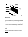
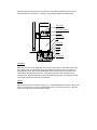
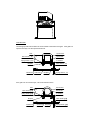
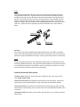
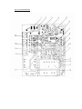
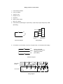
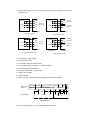
SKC-500U/E SLIDING GATE OPENER
OWNER’S MANUAL
OUTLINE
1. Safety Precautions
2. Features
3. Specifications
4. Necessary Tools
5. Site Preparation
6. Mechanical Installation
7. Electrical Installation
8. Operation
9. Trouble Shooting
10. Warranty
Gatekeeper Ltd.
P.O. Box 752
Laceys Spring, AL 35754
http://www.gatekeeperltd.com
© 2005-2007
GatekeeperLtd All Rights Reserved
IMPORTANT SAFTEY INFORMATION
Installing the SKC-500U/E Gate Opener requires installation of standard
110V or 240V electrical wiring. This work should only be performed by a
trained technician. Miswiring could cause personal injury or DEATH. To
prevent the risk of electrocution, be sure to turn off all power to the SKC 500U/E until installation is complete.
•
•
•
•
•
•
•
•
•
•
•
•
•
•
•
•
•
The gate opener should be installed by a qualified technician; otherwise, serious
personal injury or property damage may occur.
Before installation, the clutch should be unlocked.
The auto-reverse function mus t be checked during installation to ensure that the gate
can auto -reverse in the event of obstruction.
This auto-reverse function should be regularly inspected and adjusted, if necessary.
When opening or closing the gate, do not attempt to walk or drive through the gate.
Do not touch the gate while it is in operation.
Children should not be allowed to play near or operate automatic gates.
The automatic gate opener must be grounded.
Do not attempt to go through the gate while it is still in motion.
This operator is intended for vehicular use only.
Install the gate opener on the inside of the property, DO NOT install it on the outside
of the property where the public has access to it.
Be careful when in close proximity to moving parts where hands or fingers could be
pinched.
Additional safety equipment such as photoelectric sensors, safety edges, roller
guards and warning signs must be installed to prevent injury.
Do not allow control devices to be placed so that a person can access them by
reaching through the gate.
In the event of power failure, an emergency release key allows you to operate the
gate manually.
The opener should be switched off before repairing it or opening its cover.
Please erase and reset the code after installing the opener.
Class I: A vehicular gate opener (or system) intended solely for use in a single family home,
or an associated garage or parking area.
ADDITIONAL FEATURES
• Keypad / single button interface.
• Infrared safety beam interface.
• Supports up to 100 RF remotes, 2 included.
• User programmable and user erasable remote codes.
• RF hopping code technology prevents thieves from guessing your remote code.
• Auto -close feature is available for this opener.
• For your safety, the SKC-500U/E will stop and reverse if is encounters an obstruction on
closing and stop when it encounters an obstruction on opening, as required by UL-325
safety standards.
• Manual key release design for emergency purposes.
• Self-locking at any position.
• Single Phase Motor
Specifications
Power supply
500U AC110V, 60Hz / 500E AC 240V, 50Hz
Motor speed
500U 1470 r/min / 500E1400 r/min
Gate moving speed
10m/min
Required electrical circuit
10A
Output torque
14N.m
Auto close time
0 - 44 sec.
Remote control mode
Single Button
Environmental temperature
-10°C - +55°C
Main unit dimension
263 ×240×153mm
MCU logic voltage
DC5V
Relay coil voltage
DC12V
Net weight
21 Kg
Emergency release key in case of p ower
failure
Necessary Tools and Equipment
The following tools may be necessary to install the SKC -500U/E Gate opener. You will need
standard and Philips screw drivers, an electric drill, wire cutters and a wire stripper, a socket
set, and possibly access to a welder.
Site Preparation
Before you begin the opener installation, the gate should be mounted and moving freely,
there should be little resistance in the movement of the gate. The gate and post must be
suitable for being automated. Check that the structure is sufficiently strong and rigid, and that
its dimensions and weights conform to those listed in the specifications table of this document.
Make sure that the gate is plumb and level. The fence posts must be mounted in concrete.
The SKC -500U/E is powered by 240V/50Hz or 110V/60HzAC power depending on model ,
therefore if you have not already done so; wire a waterproof outlet near the gate following
proper safety standards for your area. If you are not experienced with this type of wiring or if
your area requires it, hire a professional electrician to perform this as well as wire in the SKC500U/E in the electrical section. It is a good idea and required in some areas to use a GFCI
outlet or GFCI breaker. Consult your local electrical code. The SKC -500U/E requires at
least a 10A service. Make sure your electrician takes into account the voltage drop involve d in
running many feet of wire to your installation location. If an insufficient gauge of wire is used,
there will be insufficient power at the site to operate the opener.
Parts List
(1) Sliding gate operator
(1) Operator Base
(1) Magnetic limit switch
(2) Remote control
(2) Master Links
(2) 10 ft. Chain
(2) Chain Bolts
(2) Chain Brackets
(4) “U” Bolts for 2_ (51mm) for square & round gate frame
(4) 2 ¾_ (70mm) #48 Bolts for mounting operator to the base and washers
(4) 2 ½_ (64mm) Bolts for mounting Magnet brackets and washers
(4) 3 ¾_Anchor bolts, Anchors, Washers and Nuts (In the same bag with Manual release key)
(4) 5/8_ (15mm) Socket Head Cap screws for mounting chain box
(2) Manual release key
(2) Magnet brackets
(2) Magnets
2
(1) 1m BVR 0.7mm antenna
(1) Owner’s manual
Mechanical Installation
Installation and Adjustment
The SKC -500U/E Chain-driven Gate Opener operates by forcing a straight piece of chain
through its chain box. This length of chain is extended between two chain brackets located at
opposite ends of the gate. The entire configuration is shown in the diagram above .
Concrete Pad
The base unit of the gate opener requires a concrete pad in order to maintain proper stability.
The concrete pad should be approximately 24” (600mm) x 12” (300mm) x 18” (460mm) deep
in order to provide for adequate operation. The pad should be 3” (70mm) above finish grade.
Be sure to locate the pad so that it will not interfere with the gate. In locations where ground
freeze is possible, extend the pad below the frost line.
Once the gate is mounted adequately, electrical power is available, and the concrete pad is
poured, you are ready to proceed.
Anchors
You can use the anchors that are provided with the opener, 3 ¾ anchor bolts (4), anchors,
washers, and nuts. These anchors must be set into the concrete when it is poured, or you
can use wedge anchors (1/4” x 4”).
Operator Base
Mount the gate opener base to the concrete pad. The distance between the gate and the
base should be no more than 2 ½ “ (64mm). Verify that the opener is leveled properly.
Gate operator
Socket head cap screw
Chain box
Operator base
Nut
Anchor bolt
Anchor
Conduit
Cable
Concrete pad
Chain Box
Make sure the ends of the guide chain are out of the chain holes on both sides of the chain
box. Remove the cover and insert the manual release key and turn counter-clockwise to
disengage the clutch. Remove the elastic band from the shaft and line up the key on the
shaft with the sprocket at the chain box. Insert the sprocket from the chain box into the
operator shaft. Place the operator on top of the base and use (4) 5/8 “ (15mm) socket head
cap screws to mount the chain box in to the base.
Opener
Mount the gate opener to the base using (4) 2 ¾ “ (70mm) #48 bolts and washers. Make sure
there is no more than 1/8” (2mm) of space between the cover and the chain box. Check the
opener and make sure it is lined up with the gate.
Chain Brackets
Use the appropriate bolts to attach the chain bracket to the frame of the gate. If the gate is of
square frame style, use the square bolts shown.
Gate
Square frame
Plain washer (¦ 6
µ)
Square bolt
Spring washer (¦ 6
µ)
"L" bracket
Nut (M6)
Master link
Plain washer (¦ 8
µ)
Chain bolt
Nut (M8)
Spring washer (¦ 8
µ)
If the gate is of round frame style, use the round bolts shown.
Round frame
Gate
Plain washer (§ 6
¶)
Round bolt
Spring washer (§ 6
¶)
"L" bracket
Nut (M6)
Master link
Plain washer (§ 8
¶)
Chain bolt
Nut (M8)
Spring washer (§ 8
¶)
Chain
Close the gate and attach a chain bolt to the pi ece of chain that comes with the chain box
using enclosure master links. Tighten the chain bolt to the bracket with washers and nuts.
Pull the chain through the chain wheel box to the other chain bracket at the opposite end of
the gate. Connect the other end of the chain and the chain bolt, and then tighten the chain
bolt to the chain bracket. Thread up the chain by adjusting the chain bolt. Cut the chain to
length if necessary. Make sure that the chain is perfectly aligned with the chain holes on the
chain box. Tighten the chain by tightening the chain bolts at either end. See illustration
below.
Chain bolt
Chain
Master link
Electrical
The control box should be equipped with a single -phase breaker (10A). Make sure that the
power is OFF before making any electrical connections. Remove the cover of the control box,
perform the wiring and replace the cover again. (See Fig.3 and wiring notes for control board)
Power
Using 18-3 gauge electrical wire, wire a standard grounded plug to your Gatekeep er control
board using standard electricians wiring practices. Wire the opposite end of this cable to the E,
N, L contacts (block 20) of the control board. Connect L to the power or brown line, N to the
neutral or blue line, and E to the ground line (yellow/green)
Activities Covered in this section
? Remote control: With each press of the button, the gate will open, stop, close or stop
cycle. (Single -button mode)
? Auto-reverse function: After adjusting the opening force and closing force, the gate will
reverse and go open if obstructed when closing, and will stop if jammed when opening.
? Auto-close function: This feature can be selected to make the gate stay open for several
seconds before it automatically closes. The auto-close time can be adjusted to between 0 and
44 seconds.
? Pedestrian mode: This feature can be used to open gate about 0.3~1.5 meters for people
pass through.
? Safe guard (Infrared photocell): If infrared beam is broken during closing, the gate will
reverse and go open immediately. This feature will not function if the gate is in fully opened
and closed positions or during opening.
? Loop detector: If loop detector detects vehicles during closing, the gate will stop
immediately and remain stopped until the vehicles pass through the loop. After vehicles pass
through the loop, the gate will continue to close.
If loop detector detects vehicles when the gate stops, the gate will remain stop until vehicles
pass through the loop. After vehicles pass through the loop, the gate will close.
The gate will keep opening if loop detector d etects vehicles during opening. After vehicles
pass through the loop, the gate will close.
? Limit switch: The switch is used to accurately stop the gate in the open and closed
positions.
If the gate stops at opened position when the limit switch is reached, the gate will not move if
it receives open signals.
If the gate stops at closed position when the limit switch is reached, the gate will not move if it
receives close signals.
Fig.3 control board scheme
Wiring notes for control board
1.
Power switch: ON/OFF
2.
Fuse: 5 A, Ø5x20
3.
Antenna: ANT
4.
Beeper: DC12V
5.
Dip-switch
6.
Memory Card: 93C66
7.
MCU: PIC 16C57C
8.
External button switch/Keypad: T (Not used), G (Not used), K (Open/stop/close), COM
(Grounding)
T
Not used
G
K
Signal
K
Com
COM
Button switch
keypad
Control board
terminal X10
NO
com
Schematic diagram
9.
Wiring diagram
Limit switch: CL (Close limit), CO (Com), OP (Open limit) , +12V (Output power supply)
CL
COM
OP
Factory preset: NO
NC mode can be used by
adjusting dip-switch.
(See Table1)
Schematic diagram
Motor wiring
terminal
Control board
RELEASE CLOSED
SWITCH
+12V
COM
OPEN
COM/U
COM
OP
V
U
C
Not used
Wiring diagram
W
MOTOR
REED SWITCHES
CL
V
W
C
E
10. Output power supply: +12V (DC +12V), COM (CO), DET (Loop detector), I.R. (Infrared
photocell N.C)
COM
COM
I.R
GND
COM
+12V
+12V
Infrared
COM
COM
Out
Terminal
X8, No.10
Out
I.R
AC24V Terminal
X5,No.11
AC24V
Control board
Infrared
Infrared with DC input
Out
DET
GND
COM
+12V
+12V
Loop detector
Control board
Infrared with AC input
COM
COM
Terminal
X8, No.10
COM
COM
Terminal
X8, No.10
Control board
Out
DET
AC24V Terminal
X5,No.11
AC24V
Loop detector
Loop detector with DC input
Terminal
X8, No.10
Control board
Loop detector with AC input
11. Output power supply: AC24V
12. Power Indicator: LED
13. Learn button: AN (For remote control)
14. Force Adjustor (VR1): Clockwise +, Counterclockwise –
15. Power Transformer: 240V/12Vx2
16. Sampling Transformer: 110V/8.8V 4W
17. Alarm Lamp: AC240V
18. Motor Capacitor
19. Motor: U (com), V (Positive direction), W (Opposite direction), E (Earth),
Motor wiring
terminal
Control board
RELEASE CLOSED
SWITCH
COM
OPEN
COM/U
COM
OP
W
MOTOR
REED SWITCHES
CL
V
V
U
C
Wiring diagram
20. Power Input: E (Earth), L (Live), N (Neutral) AC240V AC110V
W
C
E
Magnets for Limit Switch
Install the magnet and magnetic limit switch as shown in figure below . The magnet and limit
switch are used to control the position of the gate. When the magnet is installed, release the
gear clutch and push the sliding gate manually to pre-determine the position. Fit the magnet
bracket to the gate and then tighten the gear clutch. The shorter bracket is for open position
and longer bracket is for close position. Finally adjust the magnet to the proper position by
moving the gate with the motor. The magnet should be .39 - .59 “away from the magnetic
limit switch. If it is too far away, the switch will fail to work. The distance between the magnet
and the operator should be @ ½” (12mm) with the operator cover on. Adjust the position of
the magnetic limit switch until the positions of the opening and closing meet the requirement.
Important Note: Please note the two magnet brackets (fixed plate) are different: one is
higher and another is lower. Verify and if necessary exchange the two brackets
position. Also if necessary exchange the limit switch wires CL (close) and OP (open).
Another common problem is there are two reed switches inside the magnetic limit
switch: one is upper and another is lower. The magnet position can be installed in the
middle so it inducts both reed switches. Solution: adjust the magnet upper or lower.
10-15mm
Magnet
Magnetic limit
switch inside
Gate operator
Plain washer
Spring washer
214.5mm
Magnet bracket
Nut
Bolt
Nut
Gate
? Check the power supply, grounding and wiring before running the device.
? Release the disengagement mechanism with the release key to determine whether or not
the gate can be moved manually. If everything is in good working order, tighten the clutch with
the key.
? Switch the power on and run the device to ensure that the gate is sliding smoothly.
? Adjust the magnet position until the gate opened and closed properly at the limited
positions.
? The motor is only designed to work for less than 5 minutes. If is runs continually for an
extended period of time, a thermal protector will stop it because of the high temperature .
Tuning and operation
RF Remote
Fig.2 Remote control
Button 1
Button 4
l
l
l
l
l
l
Button 2
Button 3
To add extra remote controls (Learning): Press the button ‘ AN’ (See control board
scheme No.13) on the control board, then the beeper will ring about 1 second, then
press the remote control button which you want to use, the beeper will ring about 2
seconds, with the beeper ringing each time the indicator LED2 will flash. The learning
process is finished.
Up to 100 remote controls may be used.
To erase all existing remote controls, press and hold ‘ AN’ button about 14 sec until the
beeper stops ringing. This indicates that all the remote controls have been erased
completely.
The remote control works in a single channel mode. It has four buttons. See Fig.E-2. The
function of button 1, button 2, and button3 are the same. With each press of the remote
control button which has been programmed, the gate will close, stop, open or stop cycle.
Button 1, button 2 and button 3 are used to open or close the gate. Button 4 is available
to set pedestrian mode. Note: if you canceled the pedestrian mode, the function of button
4 is same as the other three buttons.**
Warning: Notify the users that the gate is never to be operated unless it is in full view.
Additional RF Remote controls can be obtained through your dealer. To find a dealer in
North American, go to
www.gatekeeperltd.com/dealers
**Requires multi-channel mode, not available on all models.
Verify open direction: If the gate does not move in the desired direction, then you will need
to reverse the motor operating direction. You can do this by exchanging wires ‘ V’ and ‘W’,
‘OP’ and ‘CL’ , then insert the wire connector terminal block.
Obstruction Sensor
The Obstruction Sensor continuously monitors the gate movement for any obstructions. If any
obstructions are detec ted when the gate is closing, the gate will stop and reverse back to the
open position. If any obstructions are detected when opening, the gate will stop. The factory
setting is set at MAXIMUM sensitivity. You may need to increase or decrease depending on
the weight and the condition of your gate.
Adjustment of the Auto-Reverse Function
? Tuning the auto -reverse safety function : rotate the ‘Force Adj. VR1’ knob (See control board
scheme No.14) with a screwdriver. The resistance may be increased or decreased by rotating
clockwise or counterclockwise. If you turn the overload variable resistors clockwise it will
increase sensitivity. If you turn the overload variable resistors counterclockwise, it will
decrease sensitivity. NOTE: if the gate fails to reverse in the event of obstruction, then the
opening force or closing force should be checked for conformity with requirements and
adjusted accordingly. The gate will reverse if obstructed when closing, and will stop if jammed
when opening.
Please exchange wires V and W if the auto-reverse direction is wrong. Exchange wires OP
and CL if the limit direction is wrong.
WARNING: Do not attempt to tune the gate by placing your hand, arm or other body part in
the path of the gate, as serious injury could result. Damage to the gate opener motors may
also occur by placing a heavy immovable object in the path during the testing phase. Instead,
place a light object in the path (e.g., a chair or trash can) which can be pushed out of the way
without causing damage to gate motors, if the setting is still too high. Note: This auto reverse
function should be regularly inspected and adjusted if necessary. Once the tuning is complete
you may replace the cover.
Table 1 Dip-switch
(See Fig.3 terminal 5)
Position
Dip Switch
1
ON
OFF
Limit switch mode is NC.
Limit switch mode is NO.
ON
Auto-close function and auto-close function of pedestrian mode are
available.
OFF
Both Auto-close function and auto-close function of pedestrian
mode are shut off.
ON
Programming / In this position the control board is in programming
condition, NOT USE condition.
OFF
Normal / In this position the control board can be normally used.
2
3
Functi on
? Set auto-close function (This feature can be selected to make the gate stay open for
some time before it automatically closes. The auto-close time can be adjusted to between 0
and 44 seconds.): please turn on the second and the third dip-switch (See Fig.3 terminal 5) to
ON position. Press the remote control button (button 1, button 2 or button 3) tha t has been
programmed to open the gate (see Verify open direction section). Stop the gate at any
position by pressing the same button, wait for some seconds according to your requirements
(the range is 1~44 sec.), this period of time is regarded as ‘auto -close time’. Close the gate by
pressing the same button. Press the button again to stop the gate or the gate will stop
automatically at its closed position if the magnetic limit switch is reached. After this setup is
complete, return dip-switch 3 to OFF pos ition immediately. Thus the auto-close function has
been set.
? Cancel auto-close function: Please turn on the second and the third dip-switch (see Fig.3
terminal 5) to ON position. Press the remote control button (button 1, button 2 or button 3)
that has been programmed to open the gate (see Verify open direction section). Stop the
gate at any position by pressing the same button, wait until the gate close automatically (45
sec.). Press the same button to stop the gate or the gate will stop automatically at its closed
position if the magnetic limit switch is reached. After this setup is complete, return dip-switch 3
to OFF position immediately. Thus the auto-close function has been canceled.
? Pedestrian mode : Pedestrian mode can be used to open gate about 0.3~1.5 meters for
people pass through.
? Set width of pedestrian mode : Please turn on the second and the third dip-switch (See
Fig.3 terminal 5) to ON position. Press button 4 to open the gate (see Verify open direction
section), Wait until the gate travels the distance according to your requirements (the distance
range is 0.3m~1.5m or wait for 3~10 sec.), it is regarded as ‘ the width of pedestrian mode’ .
Then press the same button/button 4 to stop the gate, wait for some seconds (1~ 44 sec.).
Close the gate by pressing the same button /button 4 . Press the same button again to stop the
gate or the gate will stop automatically at its closed position if the magnetic limit switch is
reached. After this setup is complete, return dip-switch 3 to OFF position immediately. Thus
the width of pedestrian mode has been set.
If you open the gate with button 4 , the gate will stop at the expected position that you have
set.
? Set auto-close function of pe destrian mode: Please turn on the second and the third dipswitch (See Fig.3 terminal 5) to ON position. Press button 4 to open the gate (see Verify
open direction section) , wait some seconds (3~10 sec.). Then press the same button/button
4 to stop the gate, wait some seconds according to your requirements (1~44 sec.), this period
of time is regarded as ‘auto-close time of pedestrian mode’. Close the gate by pressing the
same button/button 4. Press the same button again to stop the gate or the gate will sto p
automatically at its closed position if the magnetic limit switch is reached. After this setup is
complete, return dip-switch 3 to OFF position immediately. Thus the auto-close function of
pedestrian mode has been set.
Note: the new width of pedestrian mode has been re-programmed in the device and replaced
the original width you have set in Set width of pedestrian mode section.
If you open the gate with button 4, t he gate will stop at the new expected position that you
have set, after some seconds as what you have set, the gate will close automatically.
? Cancel width / auto -close function of pedestrian mode
? Cancel both width and auto-close function of pedestrian mode: Please turn on the
second and the third dip-switch (See Fig.3 terminal 5) to ON position. Press button 4 to open
the gate (see Verify open direction section). Wait for more than 15 sec.. Then press the
same button/button 4 to stop the gate. Wait until the gate close automatically (45 sec.). Press
the same button to s top the gate or the gate will stop automatically at its closed position if the
magnetic limit switch is reached. After this setup is complete, return dip-switch 3 to OFF
position immediately. Thus the width and auto-close function of pedestrian mode have been
canceled.
? Cancel width of pedestrian mode, keep auto-close function of pedestrian mode:
Please turn on the second and the third dip-switch (See control board terminal 5) to ON
position. Press button 4 to open the gate (see Verify open direction section). Wait for more
than 15 sec.. Then press the same button/button 4 to stop the gate. Wait some seconds
according to your requirements (1~44 sec.). Then press the same button/button 4 to close the
gate, press the same button again to stop the gate or the gate will stop automatically at its
closed position if the magnetic limit switch is reached . After this setup is complete, return dipswitch 3 to OFF position immediately. Thus the width of pedestrian mode has been canceled,
the auto-close function of pedestrian mode has been reserved.
Note: the new auto-close time of pedestrian mode has been re-programmed in the device and
replaced the original auto-close time of pedestrian mode that you have been set in Set autoclose function of pedestrian mode section.
? Keep width of pedestrian mode, cancel auto-close function of pedestrian mode:
Please turn on the second and the third dip-switch (See Fig.3 terminal 5) to ON position.
Press button 4 to open the gate (see Verify open direction section). Wait some seconds
(3~10 sec.), then press the same button/button 4 to stop the gate. Wait until the gate close
automatically (45 sec.). Press the same button again to stop the gate or the gate will stop
automatically at its closed position if the magnetic limit switch is reached. After this setup is
complete, return dip-switch 3 to OFF position immediately. Thus the width of pedestrian mode
has been reserved, the auto -close function of pedestrian mode has been canceled.
Note: the new width of pedestrian mode has been re -programmed in th e device and replaced
the original width.
If you open the gate with button 4 , the gate will stop at the expected position that you have
set, but the gate will not close automatically.
? Turn on the second dip-switch to OFF position (Factory preset: OFF position), both auto
close function and auto-close function of pedestrian mode were shut off.
Install the External Keypad/ Button Switch
The SKC-500U/E is equipped with an interface for an external switch or keypad. The
interface type is a NO (Normally Open) momentary switch to ground. To activate the opener,
the keypad or other device must short the ground and K terminal momentarily. This type of
switch is very common. To install attach one lead of your keypad to the K terminal and the
other to the GND terminal. The keypad will function in single channel mode just like the RF
remote.
The terminal ‘GND’ is the common terminal, the terminal ‘K’ is used to open/stop/close the
gate circularly, ‘G’ and ‘T’ are no connection.
Table 2
No.
Terminal
1
2
3
4
+12V
COM
I.R.
COM
5
K
6
G/T
Remark
Output +12V 100mA
Ground, I.R. COM
Infrared N.C.
External keypad/button switch: COM
External keypad/button switch: Open/Stop/Close
No connection
Safe guard (Infrared device)
If the infrared beam is broken during closing, the gates will reverse and open immediately.
During opening, the beeper will ring. The control box is not factory equipped with an infrared
device.
Install the infrared device
Connect signal wire of infrared device to ‘ IR’ (see Fig.E -3 terminal X8 , No.10), connect
common wire (i.e. ‘power supply –‘) of infrared device to ‘COM’ (terminal X8, No.10), and
connect ‘ power supply +’ of infrared device to ‘ +12V’ (terminal X8, No.10).
The infrared device can be obtained through your dealer. To find a dealer in North American,
go to www.gatekeeperltd.com/dealers
Maintenance and Electrical
Every six months check the following items for proper operation of the unit
l Check the chain lubricant an d add 1# grease regularly.
l Lubricate shafts and sprockets.
l Keep opener clean at all times. Check inside cover for insects.
l Check and tighten anchors bolts.
Table 3 Troubleshooting
Trouble
Motor only runs in one direction.
By pressing button 1(button 2 or button 3)
which has been programmed to open the
gate, press the same button again to stop the
gate in required position, but the gate will
auto-close immediately.
When you use button 4 of remote control to
open the gate, gate travels too short.
When you use button 4 of remote control to
open the gate, but the gate will auto-close
immediately.
The gate will not open or close.
Remote control does not work
When you open the gate by using button
1(button 2 or button 3) which has been
programmed, gate will stop in mid-travel or
reverse before reaching the fully limit
position.
Possible causes
Solutions
The wire connector terminal block
becomes loose.
Check wire connector terminal block make
sure it is plugged in terminal block 10 (X8).
The limit switch wire connector terminal
block becomes loose.
Check limit switch wire connector terminal
block make sure it is plugged in terminal
block 9 (X9).
Check the limit switch mode.
The electric component on the control
board such as Q2, Q91 or Q92 may be
damaged.
Replace the electric component Q 2, Q91 or
Q92 (BTA16/600) or replace the board.
The auto-close time is too short.
Reset the auto-close time. See Set autoclose function section.
The width of pedestrian mode is too
narrow.
Reset the width of pedestrian mode. See Set
width of pedestrian mode section.
The auto-close time of pedestrian mode
is too short.
Reset the auto-close time of pedestrian. See
Set auto-close function of pedestrian
mode section.
The limit switch wire connector terminal
block becomes loose.
Check the limit switch mode (see table 1 Dipswitch).
Connecting wires or terminal blocks are
too loose.
Check the connecting wires and terminal
blocks.
The electric component on the control
board such as Q2, Q91 or Q92 may be
damaged.
Replace the electric component Q 2, Q91 or
Q92 (BTA16/600) or replace the board.
Power switch is OFF
Make sure power switch is ON.
The indicator light of remote control does
not light.
Check the batteries on your remote control.
Remote control is not suitable for
receiver.
After making sure the codes are correct,
erase remote controls and then re -program
the codes in the device. See Adding extra
remote controls (learning) section.
Broken receive board
Replace receive board.
The Force Adj. (VR1) is adjusted too
Check the Force Adj. (VR1). Adjust VR1 to
small.
increase force.
Gate is obstructed.
Remove the obstruction.
Link a new antenna (1~1.2m BVR 0.75mm2
The remote control operating distance is too
see parts list) to the old antenna. Then fix the
Signals are shielded by the gate.
short.
antenna on the wall vertically, make sure the
total height from the top of antenna to the
ground is approx. 1.5m.
The gate opens, but stops and will not return
.
1. Please note the two magnet brackets
(fixed plate) are different: one is higher
and another is lower. Please try to
exchange the two brackets position.
2. Please try to exchange the limit switch
wires CL (close) and OP (open).
3. There are two reed switches inside the
magnetic limit switch: one is upper and
another is lower. Maybe the magnet position
was installed in the middle so it inducts both
reed switches. Solution: adjust the magnet
upper or lower
Gatekeeper Ltd. Limited Warranty
Gatekeeper Ltd. Warrants the SKC-500U/E Sliding Gate Opener to be free of defects in
materials and workmanship for a period of 1 year from the date of purchase subject to certain
limitations.
This warranty shall not apply in the following circumstances, misuse, vandalism, accident,
neglect, unauthorized repair or modification, acts of God (lightning, flood, insect damage etc.),
power surge, corrosive environments, incorrect installation or application, damage to
mechanism due to wrong type of gate, incorrect weight, gate not operating freely or not on
level ground etc.
The warranty set forth here shall be entirely exclusive and no other warranty, either written or
oral is expressed or implied, Gatekeeper Ltd specifically disclaims any and all implied
warranties of merchantability or fitness for a particular purpose. It is the pu rchaser’s sole and
exclusive responsibility to determine whether or not the equipment will be suitable for a
particular purpose. In no event shall Gatekeeper Ltd be held liable for direct, indirect,
incidental, special, or consequential damages r loss of profits whether based on contract, tort,
or any other legal theory during the course of the warranty or at any time thereafter. The
installer, purchaser and /or end user do agree to assume all responsibility for all liability in use
of this product, releasing Gatekeeper Ltd of all liability.
For service under this warranty, please contact your dealer. All parts, accessories, service
and support for Gatekeeper products is supplied through our network of dealers. Dealer
information can be obtained at
www.gatekeeperltd.com/dealers
Gatekeeper Ltd.
P.O.Box 752
Laceys Spring, AL 35754
[email protected]
For updated versions of the manual see:
http://www.gatekeeperltd.com
For Additional Remotes, Infrared Photo Cells or
Parts please contact your dealer. To locate a
dealer, please visit us at:
www.gatekeeperltd.com/dealers
© 2005-2007
GatekeeperLtd All Rights Reserved