1
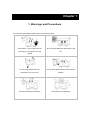
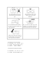
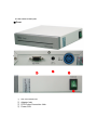
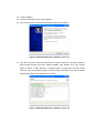
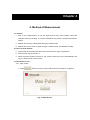
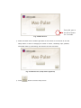
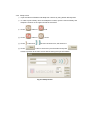
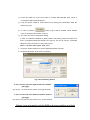
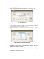
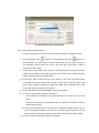
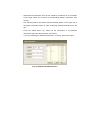
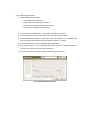
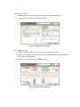
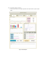
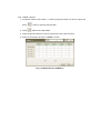
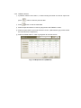
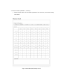
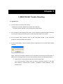
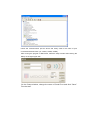
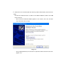
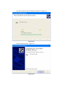
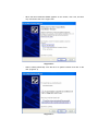
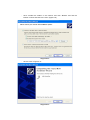
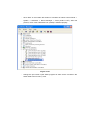
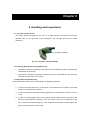
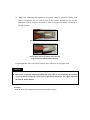
Max Pulse (For general use) User Manual Medicore., Co.,Ltd Table of Contents 1. Warnings and Precautions .......................................................................... 3 2. Product Characteristics and Contents............................................................ 6 2.1 Purpose of Using MAX PULSE ........................................................................................ 6 2.2 The Theoretical Concept of MAX PULSE ........................................................................ 6 2.3 Product contents .............................................................................................................. 7 2.4 The names of each part ................................................................................................... 8 2.5 The names of parts .................................................................................................... 9 3. Program installation ................................................................................ 10 3.1 Installation ................................................................................................................ 10 4. Method of Measurement ........................................................................... 14 4.1 Caution ........................................................................................................................... 14 4.2 Prior to measurement .................................................................................................... 14 4.3 Directions for use ..................................................................................................... 14 5. MAX PULSE Trouble Shooting ................................................................... 28 5.1 System Error ............................................................................................................ 28 6. Handling and Inspections ......................................................................... 36 6.1 The optical probe sensor ............................................................................................... 36 6.2 Checking Data Acquiring while Measuring .................................................................... 36 6.3 Equipment Troubleshooting ........................................................................................... 36 6.4 Carry ........................................................................................................................ 37 7. Maintenance and Cleanliness .................................................................... 38 7.1 Cleaning Directions ........................................................................................................ 38 7.2 Accessories Cleansing Directions ............................................................................. 39 8. SPECIFICATIONS ................................................................................... 40 8.1 Physical Specifications .................................................................................................. 40 8.2 Technical Specifications ................................................................................................ 40 8.3 Standards ....................................................................................................................... 41 8.4 Warranty .................................................................................................................. 41 Product Warranty ...................................................................................... 42 Chapter 1 1. Warnings and Precautions Do not use or keep MAX PULSE on the circumstances below. Humid place (do not the touch the Do not expose MAX PULSE directly to the power plug or equipment with wet sun. hands) Do not place MAX PULE in an Do not place MAX PULSE close to electric extremely hot or cold room. heaters. Avoid an extremely humid place Avoid shocks and vibrations. Do not place MAX PULSE close to Be cautious about a place, which chemical substances and explosive contains dirty dust and metal gas. substances. . Do not disassemble MAX PULSE. In Do not insert the power plug when this case, the product warranty may installation is not completed. Otherwise, it not be guaranteed. may lead the product to the malfunction. Tightly hold the plug when pulling out the power supply. Do not pull out the power supply during the operation Circumstances for use are as follows: l Temperature: 20℃ ~ 30℃(68℉ ~ 86℉) l Humidity: 80% RH max @40℃(104℉) l Pressure : 700hPa ~ 1060hPa Circumstances for storage are as follows: l Temperature: l Humidity: -20℃ ~ 60℃(-4℉ ~ 140℉) 95% RH max @50℃(122℉) l Pressure : 700hPa ~ 1060hPa These user instructions and directions may be changed based on software versions or the circumstances of a manufacturer without prior notice. Please feel free to contact our sales representatives or e mail us at www.medi-core.com. Caution l Do not install MAX PULSE close to electric generator, x-ray device, broadcast device, and electric shifting cable to avoid electrical noise; such electrical devices may lead to invalidity results. l Keep out of the reach from children and pets to prevent them from electric shocks. Chapter 2 2. Product Characteristics and Contents 2.1 Purpose of Using MAX PULSE HRV measures heart rate variability in a given time period and analyzes the variability to determine one’s overall health status and autonomic nerves system activities. Throughout the measurement, the levels of physical/mental stress and autonomic nerves balance are informed. The basic theoretical concept of the measurement is based on the fact that healthy adults show a wide range of the heart rate variability. In order for the measurement to be valid and reliable, time domain analysis, and frequency domain analysis are used. APG is a waveform recorded that expresses the beat of the major blood vessels and walls of the heart in accordance with the heart rate. Based on the cycle of the heart, the bore and funnel of blood vessels are changed to circulate them in peripheral nerve, which can be expressed as the waveform of arterial changes. Based on the fact that it is not impossible to measure the preliminary status of the heart by stimulating artery, a number of researches on the cardiac insufficiency have been done. By measuring the flexibilities of artery and conditions of peripheral nerve, APG provides information on the foreknowledge related to the aging level of blood vessels, atherosclerosis, and blood funnel disorders. 2.2 The Theoretical Concept of MAX PULSE MAX PULSE HRV numerically shows the level of the heart rate changes. A healthy person has the wide range of the heart rate variability. In contrast, a person who has unhealthy conditions shows a narrow variability of the heart rate. Two methods of measuring the heart rate variability are used in MAX PULSE. The time domain analysis is a statistical processing that calculates the standard deviation of the heart rate from the RR Intervals. The frequency domain analysis is a processing that quantifies the levels of each heart rate frequency. The frequency domain analysis particularly and separately provides information on sympathetic and parasympathetic nervous systems. 2.3 Product contents n Parts and items are provided as follows :. 2.3.1 Basic accessories ① Main Body : 1 pc ② Operation Manual :1 ③ 220V cable :1 ④ RS-232 to USB :1 ⑤ HRV Result sheet : 200 ⑥ APG Result sheet : 200 2.4 The names of each part © Front © Back ① ② ③ ④ ① ② ③ ④ RS-232 Serial Port Adapter Inlet PPG Probe Connection Hole Power S/W 2.5 The names of parts Type BF Power on Power off Caution HRV Heart Rate Variability Chapter 3 3. Program installation 3.1 Installation © Caution l Use MAX PULSE in inner temperature of 10℃~ 40℃ and humidity of 80%. l Check the power cable connection before its use. l Do not insert more than one power code in an electric connecter l Install MAX PULSE on a flat ground l Put the ground cable l Do not use the connector making electric codes. l Be cautious of shocks. l Be cautious of dust and flammable substances. 3.1.1 S/W installation l Insert the installation CD into PC CD-ROM. l CD is automatically processed and the popup below will be shown.. Figure 3-1 MAX PULSE Auto installation screen (1) l Click the next button. Click the cancel button in case of wanting to cancel the install. (if MAX PULSE program has been already installed, click (bottom left on the screen) startà program à MAX PULSE à Uninstall button to erase S/W and then install. However, if you uninstall the program without backing up database, you may lose all the previous data. Back up all data prior to uninstall) Figure 3-2 MAX PULSE Auto installation screen (2) l When installation is finished, the screen below will be shown. Click the finish button. ( in case of not wanting to run MAX PULSE program, make the check mark disappeared in “MAX PULSE 2.4.0 ” and the click the finish button) Fig 3-3 MAX PULSE Installation finished screen 3.1.2 Power connection l Insert one side of power code into the power terminal of MAX PULSE. l Check if the signal output and input terminals are properly connected. l Technical problems may be generated in case of an improper connection. 3.1.3 Accessory connection to equipment l Connect necessary accessories to the connection ports of the equipment. Caution l MAX PULSE can not be used with other medical devices at the same time. Otherwise, users may be in danger of getting electric shocks . Chapter 4 4. Method of Measurement 4.1 Caution ① Prior to the measurement, do not act anything that may cause sudden heart rate changes. Exercise, smoking, and certain medication may result in invalid measurement reports. ② Patients should be in relaxed state during the measurement. ③ Patients should not move or speak during the measurement, and breathe normally 4.2 Prior to measurement ① Power cable and optical probe are to be connected to the body of equipment. ② Power switch may be turned on. ③ When the power switch is turned on, the system should be running automatically and Fig. 4-1 will be shown on the screen. 4.3 Directions for use 4.3.1 Main screen ① Press button to see the screen that shows the information of patients Fig. 4-1 Main Screen Press this part at the left of mouse for 3 seconds. Fig. 4-2 Main Screen ② Press the button that is bottom right side on the screen for 3 seconds to see the setup button in case of changing the name of clinics, contacting input, patients, information back up, print setting, and volumes of voice comments. Fig. 4-3 Main Screen (setup button appeared) ③ Press button to see the setup screen. 4.3.2 Setup screen ① Input the names of facilities and telephone numbers by using bottom left keyboard. ② In order to print a facility name and telephone number, input the name of facility and telephone number on the upper left side of the screen. ③ Press button to ④ Press button to ⑤ Press ⑥ Press button and mute. sound. the more of these icons, the louder it is. button to save the input information and press button to go back to the main screen without saving the input information. Fig. 4-4 Setup Screen ⑦ Press the COM icon of the port name to choose RS-232(COM port), which is connected to Max Pulse equipment. ⑧ It can be chosen “West” or “East” reference by clicking the Combo Box under the Reference Type. ⑨ In case of pressing button, pop-up will be created, which enables users to set report print sheets. (Fig 4-5) ⑩ The value of X and Y coordinates setting In case of a difference between a sheet position and printing result, the values of X and Y coordinates should be altered in the pop-up. The unit of X and Y coordinate values is 0.1mm as shown on Title in the pop-up. (Unit: 1 = 0.1mm, basic value : X=0, Y=0 ) ⑪ Press the TestPrint button to check if adjusted position is proper. ⑫ Press the OK button to save the print setting. Fig. 4-5 Print Setting Screen X axis: The box will move right forward as numbers get bigger. (ex: input X =10, then the box moves 1mm right forward ) Y axis: The box will move down forward as numbers get bigger. (ex: input Y=10, then the box moves 1mm down forward) Please, reset and reprint until the BOX and sheet positions are fixed. ⑬ Press button to see the backup pop-up as shown on Fig. 4-6. Fig. 4-6 Backup Screen ⑭ If “Are you performing backup for the data?” is shown, push “Y” button to indicate a necessary position and then push OK button. (Fig. 4-7) ⑮ While initializing DB, the pop-up will appear, asking if you would back up the data. (Fig. 4-8) Fig. 4-7 Backup Screen (Input the saving route) ⑯ ‘The backup file will be saved in the selected folder, but the patient data will be deleted in case of pressing “Yes” button. ⑰ The patient’s data and backup file will be remained and generated, respectively in case of pressing ‘No’ button. After the backup is successfully finished, the backup finished pop-up will appear on the screen. Fig. 4-8 Backup Screen (Initializing)) 4.3.3 Examinees’ information screen ① Press the start button on the main screen to see the patients’ information screen. ② To input gender, press button for a male patient and press button for a female patient. The gender that is chosen will be shown on the screen and his or her information will be output as a list on the right side of the screen. (male is chosen as a basic value.) ③ Input gender, name, date of birth, and ID on the upper left side of the screen to see a patient’s information on the upper right side of the screen, which is identical to the patient whose information has been input. ④ Press name, date of birth, ID icons on the screen to be input. Input date of birth numerically and press the front side of year to input year of birth (ex 1979). The year of birth should be greater than 1800 and smaller than the present year. Input month and day with numbers of two places. ⑤ ID is automatically input as 00000000 if users do not need ID. ⑥ In case of newly inputting patients’ information: - Input a patient’s information on the upper left side of the screen (ID is not to be input.) - Press the next button to automatically save the patient’s information and see measurement screen. ♣ In case of newly inputting the information, do not select the patient from the list. In case of selecting the patient from the list, press the previous button to see the main screen and repress the start button to see the patient’s information screen. ⑦ In case of recalling a previous patient’s information: - Input a corresponding patient’s information on the upper left side of a patient information space. - A patient’s information will appear on the list, which is identical to the information that has been input. - Select desired information from the list. (although a patient’s all of information are not input, select one in case of a corresponding patient’s information from the list) - A selected patient’s information will automatically appear on the upper left of the patient information space in case of selecting desired information from the list. - If the selected patient’s information is identical to that of the patient for whom an examiner has looked, press the next button to see the measuring screen. - If the selected patient already has the measuring data, press the result button to the results on the screen. ⑧ In case of changing a previous patient’s information: - Input the patient’s information on the upper left side of the patient information space. - The patient’s information will appear on the list, which is identical to the information that has been input. - Select desired information from the list. (although a patient’s all of information are not input, select one in case of a corresponding patient’s information from the list) - The selected patient’s information will automatically appear on the upper left of the patient information space in case of selecting desired information from the list. - Change information in the patient information space and then press the next button. - If “Are you editing the selected information?’ is shown, press ‘Yes’ to finish the change and see the measuring screen. ⑨ In case of deleting a previous patient’s information: - Input the patient’s information on the upper left side of the patient information space. - The patient’s information will appear from the list, which is identical to the information that has been input. - Select desired information from the list. (although a patient’s all of information are not input, select one in case of a corresponding patient’s information from the list) - The selected patient’s information will automatically appear on the upper left of the patient information space in case of selecting desired information from the list. - Press the delete button. (or, delete all the information in the patient’s information space and then press the next button) - If “Are you selecting the selected information?” is shown, press ‘Yes’ button. Fig. 4-9 Patient Information Screen 4.3.4 Measurement Screen ① Check measurement position. - Set at ease when measuring. - Insert a left index finger into the sensor. - Put hands on the table comfortably and relax. - Do not move or speak while measuring. ② If all set, press the start button on the bottom right side of the screen. ③ The test button becomes the stop button post to pressing the test button. ④ As the measurement begins to start, the preview will progress for 10 seconds and then the measurement data will be automatically saved for 3 minutes. ⑤ Press the stop button in case of stopping the measurement. ⑥ The previous button is only applicable when the progress is stopped.(unable to convert it to the previous screen while measuring) ⑦ The report screen will be shown after the measurement is finished. Fig. 4-10 Measurement Screen 4.3.5 Report 1 Screen ① Press the retest button in case of going back to the measurement screen. ② Press the next button to see the report 2 screen. Fig. 4-11 Report Screen (report 1) 4.3.6 Report 2 Screen ① Press the previous button in case of going back to the report 1 screen. ② Press the print button to print out report 1 and 2. (USB exterior type printer should be connected to the equipment ) ③ Press the next button to see the TREND 1 screen Fig. 4-12 Report Screen (report 2) 4.3.7 Print Screen (report1, 2 screen) ① Press the print button on the upper right side of the report2 screen to get the report below. Fig. 4-13 Print Report 4.3.8 TREND 1 Screen ① If patients’ data are more than 5, 5 data including the latest one will be output and press ② Press button to see the previous data. button to the latest data. ③ Press the previous button in case of going back to the report 2 screen. ④ Press the next button to see the TREND 2 screen. Fig. 4-14 Report Screen (TREND 1) 4.3.9 TREND 2 Screen ① If patients’ data are more than 5, 5 data including the latest one will be output and press ② Press button to see the previous data. button to see the latest data. ③ Press the previous button in case of going back to the TREND 1 screen. ④ Press the print button to print out the trend 1 and 2. (USB exterior type printer should be connected to the equipment ) ⑤ Press the restart button in case of going back to the main screen. Fig. 4-15 Report Screen (TREND 2) 4.3.10 Print Screen (TREND 1, 2 Screen) ① Press the print button on the bottom right side of the screen to print out the history chart below. Fig. 4-16 Print Report (History Chart) Chapter 5 5. MAX PULSE Trouble Shooting 5.1 System Error 1) The wave does not show at the preview. à Check the connection between the sensor and main body. Check the sensor selection on the environment setup window. 2) Do not measure while operating the printer: As our equipment collects the data at real time, if you use the printer at the same time, it could cause the trouble in the system. 3) Do not operate other equipment while you are using MAX PULSE.: It may cause the problem to collect the data at the real time. 4) For the measurement, when the below window is appeared on the screen after clicking “Preview”. Firstly, check the connection between the PC and Max Pulse through the data cable. In spite that it is connected well, if it has the same trouble, proceed the following directions. ① When the PC is connected with the device by the serial cable, Turn off the program of Max Pulse and click as following process on the Start Menu (Setting -> Control Panel -> System -> Hardware -> Device Manager -> Port (COM & LPT). Check the communication port as above and clarify what is the name of port connected with Max Pulse. (ex. COM1, COM2, COM3) After running the program of Max Pulse, make the setup window after clicking the Setup on the right upper side. On the Setup window, change the name of Serial Port and click “Save”. Run the start. ② When the PC is connected with the device by USB to Serial cable. (Connect PC to USB) Connect the USB Connector of USB 2.0 TO RS232 CABLE에 USB to the USB circuit in the PC. - When the New Hardware Wizard appears on the screen, click “Yes, this time only” and click to the next (N). <Fig. 5-1> - Click “Install (Advanced)” from the list or a specific location and click to the next. (Figure 5-2) <Figure 5-2> - Click “Include this location in the search” and click “Browse’ and find the location of drive and click to the next. (Figure 5-3) <Figure 5-3> - The window will be shown as following the picture of <Figure 5-4>. <Figure 5-4> - Click to close the window. <Figure 5-5> <Figure 5-5> - When the New Hardware Wizard appears on the screen, click “Yes, this time only” and click to the next. <Figure 5-6> <Figure 5-6> - Select “Install (Advanced)” from the list or a specific location and click to the next. (Figure 5-7) <Figure 5-7> - Click “Include this location in the search” and click “Browse’ and find the location of drive and click to the next. (Figure 5-8) <Figure 5-8> - Click to close.<Figure 5-9> <Figure 5-9> - Click “Start” on the bottom left location of windows as follows Control Panel -> System -> Hardware -> Device Manager -> Ports (COM & LPT). After this process, check if the USB Serial Port (COM3) is installed properly. . <Figure 5-10> - Change the port name in Max Pulse program as same as the connection the serial cable to the PC like ① case. Chapter 4 6 6. Handling and Inspections 6.1 The optical probe sensor The optical probe is designed to be worn on a finger and be connected to the sensor adhesive part on the right side of the equipment. The red light should be on while measuring. Red light emitting Fig. 6-1 Part of the red light emitting 6.2 Checking Data Acquiring while Measuring ① The sensor is properly operating if waveforms are expressed along with the stable heart rate (60-80) on the screen. ② The sensor is improperly operating if waveforms are not expressed with the abnormal values of the heart rate on the screen. 6.3 Equipment Troubleshooting Read the directions below when the equipment is improperly operating: ① In case of not being able to turn on the power: Check whether AC is properly connected. Check connecting switch conditions. ② In case of waveforms being abnormally expressed: Check whether the surface of rooms is flat. ③ In case of not being able to print out the results: Check whether there are sheets in the printer; the light should be emitting on the error ramp if there are no sheets left in the tray. Contact the authorized agency if the problems continuously emerge despite the light not presenting on the error ramp. ④ Naked eye measuring and emergency procedures: Retry to connect the sensor to a finger if waveforms are too small to see on the screen. Waveforms may not be presented or be too small on the screen in case of a finger not properly connecting to the optical probe. (a)The upper side of the optical probe wearing (b)The lateral side of the optical probe wearing Fig. 6-2 proper optical probe wearing A signal detonator may not function properly due to manicure or long finger nails. Caution l The sensor of a probe must be handled with extra care for its sensitivity. Do not drop or give a shock, which may cause serious operational problems. The cables must not be close to sharp objects. 6.4 Carry Hold the body of the equipment with two hands when carrying. Chapter 7 7. Maintenance and Cleanliness It is recommended that the body of Nano-Pulse and accessories always be cleanly maintained. The free repair service does not cover any damages caused by using any substances that may lead to product damages Cautions l Recheck the sensor and body of the equipment after cleaning them. l In case of obsolete or equipment damages do not turn on the power switch. Call the A/S center. 7.1 Cleaning Directions ① Use warm water or alcohol on a soft cloth to clean and remove dust. Never use thinner, ethylene or oxidized substances, which may cause product damages. ② Cables and accessories should be kept free of dust or dirt and wipe down them with an warm water (40℃/104℉) soaked cloth. ③ Never soak accessories in any liquids or detergents. Any liquids must not be inserted to the equipment and accessories. 7.2 Accessories Cleansing Directions ① The optical probe Refer to the table below when sanitizing and cleaning the optical probe. Chemical Substances Alcohol Isopropyl alcohol Direction Soak a soft cloth in it and wipe down 0.05 W/V%(1:200 dilution) Liquid Soap Benzalkonium Chloride Soak a soft cloth in it and wipe down 0.01 W/V%(1:50 dilution) Soak a soft cloth in it and wipe down Iodine Povidone-Iodine Gulutaral C 5H 8O 2 0.02 W/V%(1:50 dilution) Soak a soft cloth in it and wipe down 2 W/V%(Laboratory solution) Soak a soft cloth in it and wipe down Cautions l The free repair service does not cover any damages caused by using any substances that may lead to product damages. l Recheck the sensor and body of the equipment after cleaning them. l Do not use the equipment in case of obsoleteness or damages Chapter 8 8. SPECIFICATIONS 8.1 Physical Specifications 8.1.1 Size (W x D x H) 310mm x 240mm x 30mm 8.1.2 Weight About 650g 8.2 Technical Specifications 8.2.1 PPG - Measurement range : 30 ~ 240BPM - Accuracy : ±2% - Wave-out time : 2sec - Averaging(after setting time) 8beats - Pulse wave/Heart rate 8.2.2 Display parameter - Pulse wave - Accelerated pulse wave - Condition of blood vessel - HRV 8.2.3 Environmental Specification - Temperature Range Operating : 10 ~ 40 (50 ~ 104 ) Storage : -20 ~ 60 (-4 ~ 140 ) - Relative Humidity Range Operating : 80% RH max. @40 (104 ) (without condensation) Storage : 95% RH max. @50 (122 ) - Atmospheric pressure Range Operating : 700hPa ~ 1060hPa - Electromagnetic Compatibility : Radiated and conducted electromagnetic energy per CISPR 11, Class A 8.3 Standards 8.3.1 Safety Standards -Protection class -Degree of Protection class Type BF 8.3.2 Electrical -Power Requirements : 100 ~ 240VAC, 50/60Hz, 1.0A -Power Fail Protection 8.4 Warranty - Standard : 1 Year Warranty(except PPG probe) from the date of purchase ∗ Ü This specification may be changed without notice. ∗ The standard warranty period for PPG probe is 6 months from the date of purchase. Product Warranty ☞ This product has passed strict inspections and test. ☞ Medicore Co.,Ltd. warrants that operational defects or product defects will be repaired free of charge for a period of 1 year from the date of purchase. ☞ During a period of 1 year from the date of purchase, reasonable repair fees may be charged if the repair requires extra costs. ☞ This warranty must be represented to the authorized agency when repair is required. ☞ As previously stated, this warranty shall only apply to operational defects or product defects under the proper using circumstances. Warnings and precautions stated in this manual must be observed. ☞ This warranty shall not apply to any defects caused by natural disasters, unusual circumstances, or external factors such as a fire, flood, storm, tidal wave, thunder storm, earthquake, burglary, and disassembly. ☞ The repair service does not cover any surface damages or defects, which does not affect proper operation. ☞ The warranty shall not be applied to defects resulting from damaged or torn out the WARNING sticker ( ) from main set. ☞ Medicore Co., Ltd. shall not be liable for direct, indirect, or incidental or consequential related to the use of the equipment. ☞ Cosumers’ actual damages caused by an operational defect must refer to the provisions of consumer compensation issued by the Ministry of Strategy and Finance. ☞ If this product is discontinued, A/S parts may be kept in the authorized agency for 5 years in accordance with Medicore Co.,Ltd. service guides and the provisions of consumer compensation.