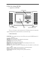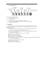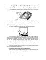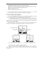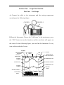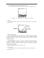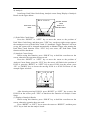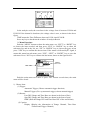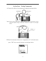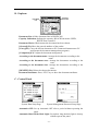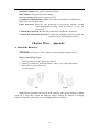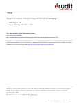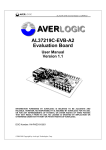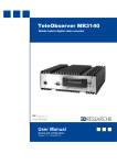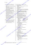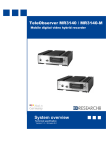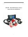
1
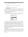
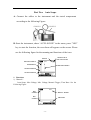
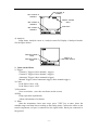
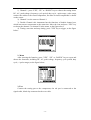
MT3500 Hand-Held Engine Analyzer
Safety Operation Regulations
-1-
Chapter One
Introduction
A. Notice of Usage:
MT3500 Hand-Held Engine Analyzer must be operated by trained professionals,
who must know all the particulars of automobile mechanism, electric devices and
circuits, when in use, the user must know how to avoid the possible danger and injury
to the user himself, his workmates, tested automobile and the related instruments. So
the user must read carefully the following detailed Safety Operation Regulations.
Safety Operation Regulations
1. Try to use the instrument in the ventilating environment, if the environment is not
ventilated, please let the auto gas out.
2. Flame is strictly prohibited near the fuel system, including smoking and
electric-strike fire.
3. Keep normal distance between the instrument and the automobile moving parts,
such as driving strap, fan gear and so on.
4. Protect your skin and the instrument from battery electrolysis liquid.
5. Don’t use electrical conductive object to connect the battery anode and cathode.
6. When use the instrument while engine is running, place the brake device to
“Parking” position.
7. Keep the instrument from oil, water, cooling compound and other kind of liquid.
8. Non-auto maintenance is strictly prohibited.
9. When install extended module and components, first turn off the power.
10. Make sure that all connectors are connected well before testing.
11. When changing batteries, first disconnect all the testing cables and turn off the
power.
12. Don’t use the instrument without anti-slippery covers.
13. Don’t use the testing cables and connectors with broken insulated scarfskin.
14. Strictly prohibit putting into DC and AC over 500 V to the signal input terminal.
15. Strictly prohibit using broken or non-appointed cables and connectors when test
the secondary ignition.
16. Don’t touch the parts that can cause high voltage when testing the secondary
ignition.
17. Before testing the secondary ignition, connect the testing cables to the instrument
first, and then connect the cables to the engine.
18. Strictly prohibit using the instrument when the connectors are not connected well
to the engine
19. Strictly prohibit connecting the testing clips or testing connectors directly to the
electrical inductive parts of secondary ignition circuit.
20. Serial Com port is used to connect with computer and port of extended module,
strictly prohibit connecting the non-appointed cable or equipments to the ports.
21. After use, disconnect all the testing cables and clips and store them in the
MT3500 case.
-2-
B. How Get to Know MT3500
1. Appearance of MT3500:
KEYBOARD
CH1
CH2
CH3
CH4
CH5
CH6
LINK
HELP
LIGHT
ON/OFF
INSERT
DELETE
SAVE
MENU
HOLD
NO
YES
F1
F2
F3
F4
LEFT HANDGRIP
LCD
RIGHT HANDGRIP
There are 18 buttons on the keyboard; the LCD display shows the testing data,
signal oscillogram and operation directions. (See the above fig.)
2. Button Functions:
[POWER]: Power supply; turn on or turn off the power (press POWER button for 1
second.)
[LIGHT]: Background light.
[HELP]: Press this button for the timing help information.
[INSERT]: Insert necessary characters
[DELETE]: Delete unnecessary characters.
[SAVE]: Save the testing data and signal waveform displayed on the screen.
[MENU]: Show the operation programs.
[HOLD]: Keep hold; keep hold or continuously show the dynamic waveform and
data.
[NO]: Withdraw; withdraw present operation or operation programs.
[YES]: Confirm; confirm the present chosen items
[▲][▼][ ][ ]: Directions; moving of cursor, position and focus.
-3-
3. Connecting ports:
SCOPE CHANNEL2/
SECONDARY
SECONDARY
SECONDARY
IGNITION
IGNITION
IGNITION
SCOPE CHANNEL1/ CHANNEL2
SECONDARY CHANNEL4 SECONDARY CHANNEL6
SECONDARY
EXTERNAL POWER SUPPLY/
IGNITION
IGNITION
IGNITION
COMMUNICATION PORT
CHANNEL3
CHANNEL5
CHANNEL1
Oscilloscope and Digital Meter:
Input Channel: CH1, CH2.
Secondary Ignition Test:
Input Channel: CH1, CH2, CH3, CH4, CH5, CH6.
Communication with PC and Extended Module, External Power Supply:
RS232 Serial Com Port.
C. Functions
With the help of powerful functions, MT3500 Hand-held Engine Analyzer
supplies serial testing items, and meets serial testing demands; the following is the
function explanation:
★ Dual-track oscilloscope can directly test the signal waveforms and data, AC
and DC voltage, frequency, Pulse-Width and duty cycle.
★ There are six testing channels that can test the secondary ignition of the six
cylinders at the same time.
★ The accuracy of Time Base Display is up to 125 uS/DIV.
★ The functions of digital meter.
★ Functions of testing components.
★ Storage capacity is more than 32Mb.
★ Power Supply: 3 pieces of batteries, low consumption design, and AUTO OFF function
can last the life of batteries.
★ Document and data management function.
★ Function of system setup.
★ Direct installation of application.
-4-
Chapter Two
Section One
How to Use The Instrument
Analysis of Secondary Ignition Test
1. According to the following figure, connect the testing cable to MT3500 and
the tested components:
CONNECTOR
CLIP
IGNITION
TESTING
CLIPS
2. Press the “POWER” button for over 1 second, when the “BEEP” appears, the
instrument begins to work.
3. Move the cursor to “Ignition Tester” position, press “YES” button to enter.
A. Single Cylinder Ignition Waveform Test:
Entering the position of “Ignition Tester”, the following figure appears:
CYLINDER CHOICE
VOLTAGE RANGE
TIME BASE
4KV/d
CH1
SIGNLE MULT
BAR
2mS/d
REC
Press F1/Right/Left buttons to choose voltage range and cylinder number, for
instance, the secondary ignition voltage is usually 5---8Kv, move the cursor to the
position shown in the figure, press “YES” Button for the Range Menu, and then press
the “UP” and “DOWN” button to choose the needed ranges. There are following
voltage ranges: 1kV/DIV, 2kV/DIV, 4kV/DIV, 6kV/DIV, 10kV/DIV.
To choose the cylinder number is as the same as to choose the voltage ranges,
first choose the cylinder number: No.1---No.6, every number is corresponding to the
input channel CH1---CH6.
Observe the secondary ignition waveforms of every cylinder, compare with the
data from the maintenance manual book:
If the ignition voltage is higher, the reason may be that:
★ The resistance of the secondary ignition system is stronger (distributor cable,
cap of the distributors, distributors, spark plugs).
★ The mixed gas is lean.
★ Compressed pressure is high.
-5-
If the ignition voltage is lower, the reason may be that:
★ Clearance between spark plugs is too narrow, or the spark plugs are smeary.
★ There is creepage in the secondary ignition system.
★ The mixed gas is too rich.
★ The compressed pressure is too low.
In the secondary ignition system, the burning time is between 1---3 ms, and
every cylinder has the same time, and the waveform is a straight line.
B. Test of multi-cylinder Ignition:
After entering ignition tester, press F2 to enter into multi-cylinder test, at this
time, three choices in the backwards third line appears on the screen:
1. Voltage Range Setup: 1kV/DIV, 2Kv/DIV, 4Kv/DIV, 6kV/DIV, 10kV/DIV.
2. 3D Visual Angle Setup: to set up the position and 3D range order; working
with Time Base, rang the cylinder waveforms as a willing format of 3D, parataxis or
exhibit. See the following figure:
Move the cursor to Visual Angle, press YES key, press the direction keys to
change the 3D ranged position of the multi-cylinder waveforms on the screen.
3D VISUAL ANGLE SETUP
TIME BASE
VOLTAGE RANGE
4KV/d
SIGNLE
3D
MULT
2mS/d
BAR
REC
Four-Cylinder Three Dimensional Waveforms
4KV/d
SIGNLE
3D
MULT
8mS/d
BAR
10KV/d
REC
SIGNLE
Four-Cylinder Parataxis Waveforms
MULT
3D
BAR
2mS/d
REC
Six-Cylinder Exhibit Waveforms
3. Time Base Setup: 2mS/DIV, 4mS/DIV, 8mS/DIV.
Analysis: Compare with the secondary ignition waveforms of every cylinder, if
one of the cylinder’s waveform is different from the others, please test and analyze
this cylinder.
-6-
C. Functions of Bar Chart:
Press the function key F3:
Cylinder No:
Data Display: Ignition testing data.
Engine Rotation Speed: Engine present rotation speed.
Testing Items: Spark voltage, burning voltage, Burning time.
This function shows the three characteristics of numerical value of ignition
waveforms in the forms of Bar Chart, it is convenient to make transverse contrast
between the ignition conditions of very cylinder, press the YES key and direction key
to choose spark voltage, burn voltage and burn time.
DATA DISPLAY
CYLINDER NO.
ENGINE ROTATION
SPEED
ITEM:
SIGNLE
SPARK
MULT
RPM:1250
BAR
REC
Four Cylinder Ignition Voltage Bar Chart
Analysis Methods: Check if the ignition parameter of very cylinder is balance, if
find some of the parameters are too high or to low, please give a specific waveform
analysis to the cylinder and then confirm the fault.
1. Compare the ignition waveform Bar Chart and data with the original data in
the Maintenance Manual, the data difference of every cylinder is within 1kv—3kv.
This is a timely test record, if need more accurate data, test first and lay aside the test
result for a short time, and then compare the test data with the original data in the
Maintenance Manual.
2. Basic Burn time: about 2ms. If the burning period is shorter than 1.3ms, the
fault reason may be that the resistance in the secondary ignition system is too strong,
the mixed gas is too lean, or the compression pressure is too high; if the burning
period is longer than 3ms, the reason may be that there are oil blots on the spark plugs,
the mixed gas is too thick, or the compression pressure is too low.
3. Every Bar Chart represents the value of the ignition voltage in every cylinder,
this is a timely test record, if need more accurate data, test first and lay aside the test
result for a short time, and then check if the tested result is within the original data in
the Maintenance Manual, if one or more cylinder’ data is below 1.5kv, the fault
reason may be that the mixed gas is too thick, the gap of spark plugs is too narrow, or
the compression pressure is too low; if one or more cylinder’ data is above 4.5kv, the
fault reason may be that the mixed gas is too lean, the gap of spark plugs is too wide
or the compression pressure is too high.
-7-
D. Recorder:
After entering the secondary ignition waveform, press F4 (Seen as figure).
IGNITION RECORD
CYLINDER NO.
ENGINE ROTATION
SPEED
TESTING ITEMS
ITEM:
SIGNLE
SPARK
MULT
RPM:1250
BAR
REC
Cylinder NO.: The number corresponding to the shown data.
Testing Items: Ignition Voltage, Burning Period, Burning Voltage.
Ignition Record: Record ignition data in a period.
Engine Rotation Speed: Present engine rotation speed.
This function shows the changing curve chart in a period, it is convenient to
make portrait comparison for the ignition in every cylinder.
Analysis Methods: Check the efficiency curve recorded in a period, if one curve
of some cylinder is greatly undulate, this means that there is some fault in the
cylinder.
E. Menu Functions:
Press the MENU key, appears the following four items:
1. SETUP: use the icon to choose the item, press the YES or Direction key to choose:
(1) Choose cylinder’s numerals 2, 3, 4, 5, 6, 1 is not available.
(2) Stroke Choose: 2 Stroke、4 Stroke.
2. Document: Use icon to choose the item, press YES to record the waveform.
3. Help: Use icon to choose item, press YES key, HELP includes:
Diagnostic Directions ( supplying diagnostic help on line).
(1). Normal Range
(2). Ignition Voltage:
Ignition voltage is too high
Ignition voltage is too low
(3). Burn Voltage:
Burn Voltage is too high
Burn Voltage is too low
(4). Burn Time:
Burn Time is too long
Burn Time is too short
About…display the diagnostic software information of secondary ignition.
-8-
Section Two
Scope Test Fuction
Part One
Lab Scope
A. Connect the cable to the instrument and the testing components
according to the following figure:
CHANNEL1
CHANNEL2
B. Start the Instrument, Choose the “Lab Scope” in the main menu, press
the “YES” button to start the function, and the waveform will appear on
the screen. In the following figure, you can find the functions of every
icon and the methods of setup.
CHANNEL1
RANGE
TTIGGER CHANNEL
INDICATION
VOLTAGE
RANGE SCALE
CHANNEL1
RANGE
TIME
BASE
LAUNCH ICON OF
PEAK-VALUE CATCH
WAVEFORM OF CH2
CH2 ZERO
POSITION
ANALYSIS CURSOR B
TRIGGER SETUP
WAVEFORM OF CH1
CH1 ZERO
POSITION
TIME BASE
SCALE
ANALYSIS CURSOR A
FUCTION SETUP
SHEET
HOLD ON
Singl Trig
SCALE
POS
-9-
CURSA RESL
TRIG ANALYZ
1. The bottom line on the screen is Function choice.
Press the “Fn” button to switch the Function Choice, see as the figure below:
F1
F1—Range
F2
F2—Zero Position
F3
F4
F3—Trigger
F4—Analyze
1). Range:
Item Setup: Channel 1 range setup, time base setup, Channel 2 range setup, as
the figure below:
TIME BASE
SETUP
CHANNEL1
RANGE SETUP
CHANNEL2
RANGE SETUP
(1) Channel 1 Range Setup:
Press the direction key to move the cursor to Channel 1 Range, the range
includes: HIDE (Shut off the channel 1 display on the screen), 25Mv/DIV, 50Mv/DIV,
0.1V/DIV, 0.2V/DIV, 0.5V/DIV, 1V/DIVE, 2V/DIV, 5V/DIV, 10V/DIV, 20V/DIV,
50V/DIV, 100V/DIV.
(2) Time Base Setup:
Press the direction key to move the cursor to Time Base, Time Base includes:
125uS/DIV, 250uS/DIV, 500uS/DIV, 1mS/DIV, 2mS/DIV, 5mS/DIV, 10mS/DIV,
20mS/DIV, 50mS/DIV, 0.1S/DIV, 0.2S/DIV, 0.5S/DIV, 1S/DIV, 2S/DIV, 5S/DIV,
10S/DIV, 20S/DIV, 60S/DIV.
(3) Channel 2 Range Setup (same as channel 1 setup).
2). Zero Position:
Item Setup: Channel 1 Zero Position Setup, Channel 2 Zero Position Setup,
As the figure below:
- 10 -
CHANNEL1
RANGE SETUP
CHANNEL2
RANGE SETUP
(1) Channel 1 Zero Position Setup:
Please make sure that Channel 1 Range Choice is in the non-hide state before
operation. Press the direction key to move the cursor to Channel Zero Position, now,
on the screen appears the flash of Channel 1 Zero Position, then press the “Up” and
“Down” key to move the zero display position on the screen.
(2) Channel 2 Zero Position Setup (same as the setup of Channel 1 Zero Position
Setup).
3). Trigger:
Item Setup: Trigger Slope Setup, Trigger Channel Choice Setup, Trigger Level
Setup. As the figure below:
TRIGGER CHANNEL
CHOICE SETUP
TRIGGER SLOPE
SETUP
TRIGGER LEVEL
SETUP
(1) Trigger Slope Setup:
Press the “LEFT” or “RIGHT” key to move the cursor to Trigger Slope Setup,
and then press the “UP” or “DOWN” key to choose the Trigger Slope: up slope or
down slope.
(2) Trigger Channel Choice:
Press the “LEFT” or “RIGHT” key to move the cursor to Trigger Channel, and
then press the “UP” or “DOWN” key to choose the Trigger Channel: Channel 1 or
Channel 2.
(3) Trigger Level Setup:
Please make sure that the Range Choice of the chosen channel is in the non-hide
state before operation. Press the “LEFT” or “RIGHT” key to move the cursor to
Trigger Level Setup, now, on the screen appears the flash of “Trigger Setup”, and
then press the “UP” or “DOWN” key to move “Trigger Setup” display position on the
screen. The voltage that the Trigger Setup Symbol corresponds to is the trigger level.
- 11 -
4). Analysis:
Item Setup: Peak-Value Catch Setup, Analysis cursor Setup, Display of Analysis
Result. As the figure below:
ANALYSIS CURSOR
SETUP
PEAK-VALUE CATCH
SETUP
DISPLAY OF
ANALYSIS RESULT
(1) Peak-Value Catch Setup:
Press the “RIGHT” or “LEFT” key to move the cursor to the position of
Peak-Value Catch Setup, and then press “YES” key, on the top right corner appears
the starting-use icon of Peak-Value Catch. If “Automatic Trigger Function” has been
set up, the system will be changed automatically to Manual Trigger after starting the
Peak-Value Catch function. Press “YES” key once more, the Peak-Value Catch
function will be shut down.
(2) Analysis Cursor Setup:
Before using this function, press “HOLD” key to hold the waveform on the
screen, otherwise the operation does not work.
Press the “RIGHT” or “LEFT” key to move the cursor to the position of
Analysis Cursor Setup, press the “YES” key, the cursor will flash in the position of
ICON A; press the “RIGHT” or “LEFT” key to move ICON A on the screen; press
“UP” or “DOWN” key to choose the moving ICON A or ICON B. Please see the
example figure as below:
After choosing moving ICON B, press “RIGHT” or “LEFT” key to move the
ICON B on the screen: press “YES” to shut down the Function of Analysis Cursor
Setup.
(3) Display of Analysis Result:
Before using this function, press “HOLD” key to hold the waveform on the
screen, otherwise operation does not work.
Press “RIGHT” or “LEFT” key to move the cursor to “RESILT”, and then press
“YES” key to look into the analysis result:
- 12 -
In the analysis result, the waveform in the voltage form is between ICONA and
ICON B. If the channel is shut down, the voltage value is zero, as shown in the above
figure.
TIME means the Time Difference between ICON A and ICON B.
Press any key to shut down the window of Analysis Result.
2. Menu Functions:
Push the “MENU” button to show the main menu, use “LEFT” or “RIGHT” key
to choose the items needed, and then press “YES” or “DOWN” key to show the
sub-menu list, and in the list, use “UP” or “DOWN” key to choose the item, at last
press “YES” key to confirm the chosen item. If the menu is followed by▼ signal, it
means this menu has sub-menu, press “YES”, “LEFT” or “RIGHT” key to open the
sub-menu. Press “NO” key to return to the last menu, shown as the figure below:
CURRENT
SELECTION
MAIN MENU
Push the main menu once more or press “NO” button several times, the main
menu will be closed.
1). Choose Item:
(1) Trigger:
Automatic Trigger (Choose automatic trigger function)
Manual Trigger (Give up automatic trigger, choose manual trigger)
(2) Reseau:
Line DIV (Range and Time Base are shown in the form of line)
Spot DIV (Range and Time Base are shown in the form of spot)
HIDE (Hide the Range DIV and Time Base DIV of the waveforms)
(3) Caption:
Display (Display the information of Range Channel, Time Base
Channel and Trigger Channel)
- 13 -
HIDE (Hide the above information)
2). Document:
Save the waveforms (Save the waveforms on the screen)
3). HELP:
HELP (General Scope operation Manual)
3. Holding Functions:
Press (HOLD) key to hold the waveforms on the screen, “the hold-on icon will
appear on the up-right corner. Press (HOLD) once again, the holding function stops.
After setting up the Peak-Value Catch Function, if the caught peak value pulse
accords to the setup conditions, the data on the screen will be held automatically,
press “HOLD” key to release the “HOLD” function.
4. Save the Waveforms:
Please choose the (Save Waveform) in the menu or press (SAVE) to save the
waveforms on the screen, at this time the following draft will appear on the screen:
The system gives automatically a new name to the document, if you need a
self-decided name, press (YES) to change the document name. After the document
name is confirmed, press (SAVE) key that corresponds to F1 to save the document, or
press (DELETE) key that corresponding to F2 to cancel the saving operation.
Editing of the Document Name: Press (YES) key to edit the document name, in
the editing column, flashes an icon. Press the (LEFT) or (RIGHT) key to chose the
needed letter; press (UP) or (DOWN) key to change the letters. (INSERT) is used to
insert a needed letter; (DELETE) used to delete a letter; (YES) key is used to confirm
the edited document and exit the editing function; (NO) is used to cancel the edited
document and exit the editing function.
5. TESTING:
Start the instrument, chose auto scope, press (YES) key, and chose the suitable
ranges and time base according to the tested items. Connect the cables to the tested
components, the red meter pen connected to the signal cable, black meter pen
connected to Zero cable, the waveform on the screen is the waveform of the tested
components, compare the waveform with the normal waveform, analyze the
waveform stat.
- 14 -
Part Two
Auto Scope
A. Connect the cables to the instrument and the tested components
according to the following Figure:
CHANNEL1
CHANNEL2
B. Start the instrument, chose “AUTO SCOPE” in the menu, press “YES”
key to start the function, the waveform will appear on the screen. Please
see the following figure for the meaning and functions of the icon:
HOLD ON
LAUNCH ICON OF
PEAK-VALUE CATCH
ANALYSIS CURSOR A
TRIGGER SETUP
ANALYSIS CURSOR B
CH2 ZERO POSITION
CH1 ZERO POSITION
1. Functions
1). Channel 1
Item Setup: Max Voltage, Min. Voltage, Manual Trigger, Time Base. See the
Following Figure:
MAX.
VOLTAGE
MANUAL TRIGGER
MIN.
VOLTAGE
TIME SETUP
- 15 -
(1) Max. Voltage:
Set up the max voltage that can be shown in the area of waveforms, move the
cursor to the position of max. Voltage item, and then press (YES) key, the following
form will be shown on the screen:
Use (UP) or (DOWN) key to chose the max. Voltage, press (YES) key to
confirm or press (NO) key to give up.
(2) Min. Voltage:
Set up the min. voltage in the area of waveform, the min. voltage is as
follow:-0.2V, -1V, -2V, -6V, -14V, -30V, -60V, -120V.
(3) Manual Trigger Setup:
Only chose the function in the Menu, the Trigger Setup can be shown on the
screen.
Use the direction key to move the cursor to the position of Trigger Setup, press
(YES) key, the setup icon will flash, at this time, use (UP) or (DOWN) key to set up
Trigger Balance; use (RIGHT) or (LEFT) to set up trigger slop.
(4) Time Setup:
Set up the waveform time gauge, the list is as following: 625uS, 1.2mS, 5mS,10
uS, 25uS, 50uS, 100uS, 250uS, 500uS, 1S, 2.5S, 5S, 10S, 25S, 100S, 300S. See the
figure below:
10mS
2). Channel 2: same as the setup of Channel 1.
3). Double Channel:
Setup Items: Max.Voltage in Channel 1, Max. Voltage in Channel 2, Min.
Voltage in Channel 1, Min. Voltage in Channel 2, Manual Trigger Setup, Time Setup,
See the figure below:
- 16 -
MAX. VOLTAGE IN
CHANNEL 2
MAX. VOLTAGE IN
CHANNEL 1
MANUAL TRIGGER
SETUP
MIN. VOLTAGE IN
CHANNEL 2
TIME SETUP
MIN. VOLTAGE IN
CHANNEL 1
4). Analysis:
Setup Items: Analysis cursor A, Analysis cursor B, Display of analyzed results.
See the figure below:
ANALYSIS CURSOR B
SETUP
DISPLAY OF
ANALYSZED RESULTS
ANALYSIS CURSOR A
SETUP
2. Items on the Menu
1).Trigger
Channel 1 Trigger (chose channel 1 trigger)
Channel 2 Trigger (chose channel 2 trigger)
Automatic Trigger (chose automatic trigger)
Manual Trigger (cancel automatic trigger, chose manual trigger)
2).Catch
Peak-Value Catch---ON
Peak-Value Catch---OFF
3).Documents
Save waveforms…(save the waveforms on the screen)
4).Help
Help (operation explanation)
About (information of software)
3. Test
Start the instrument, chose auto scope, press “YES” key to enter, chose the
suitable ranges and time base according to the testing items. Connect the cables to the
tested components, red pen is connected to the signal cable, black pen connected to
the ground.
- 17 -
Section Three
Digital Meter
Use Channel 1 and Channel 2 as universal meter testing channel to test the
voltage data, frequency, cycle periods, duty cycle and pulse range.
A. Connect the cable to the instrument as shown below:
CHANNEL1
CHANNEL2
B. Start the instrument, chose digital meter in the main menu, press
“YES” key to start the function, in the figure below, you can find the
explanations of functions, meanings and setup methods.
1. At the bottom line is the function choice.
Press “Fn” to choose the testing functions, as the figure below:
F1--Channel 1
F2--Channel 2
- 18 -
F3--Double Channel
F4--Timing
1). Channel 1: press “YES”, “UP” or “DOWN” keys to choose the testing items:
DC, AC, peak voltage, frequency, cycle period, duty cycle, +pulse range, -pulse range,
connect the cables to the tested components, the data of tested components is shown
on the screen.
2). Channel 2: as the same as Channel 1.
3). Double Channel: this instrument has the functions of double channel test,
which can test two components as the same time. Move the icon and press “YES” key
to choose the channel 1 or channel 2 in the menu, as the figure above.
4). Timing: start time and stop timing, press “YES’ key to trigger, as the figure
below:
2. Menu
After entering the function, press “YES”, “UP” or “DOWN” keys to open and
choose the functions, including DC, AC, peak voltage, frequency, cycle period, duty
cycle, +/-pulse ranges, as the figure below:
3. Test
Connect the testing pen to the components, the red pen is connected to the
signal cable, black clap connected to the zero cable.
- 19 -
Section Four Testing Components
A. Connect the cables to the instrument according to the figure below:
CHANNEL1
CHANNEL2
Note: During testing some sensors such as knocking sensor and magnetic electric
sensor, the system will give a hint that “Connect AC Coupler”, see the figure
below:
CONNECT AC
COUPLER
B. Start the instrument: choose the “Components test” in the main menu,
press “YES” key to start the function: see the figure below:
- 20 -
Functions:
1) Testing Items: Press “UP” or “DOWN” keys to move the cursor to the Component Choice,
scope range, scope time base, testing input, press “YES’ key to trigger, after
choosing the components, the HINT will appear first on the screen, see the
figure below:
Scope Ranges: 25mV/DIV, 50mV/DIV, 100mV/DIV, 200mV/DIV, 500mV/DIV,
1V/DIV, 2V/DIV, 5V/DIV.
Scope Time Base: 125uS/DIV, 250uS/DIV, 500uS/DIV, 1mS/DIV, 2mS/DIV,
5mS/DIV 10mS/DIV, 20mS/DIV.
Testing Channels: CH1, CH2, CH3, CH4, CH5, CH6.
2)Scope: Tested components, scope ranges, scope time base, testing channels.
3)Digital Meter: There are six testing functions, Max. Values, Min. Values, Frequency,
Duty Cycle, Peak Value.
Section Five
Other Functions
A. Waveform Recall
The instrument has a storage room of 32Mb. Press “SAVE” key to save the
useful waveforms. When the waveforms are needed, use this function to recall them:
move the icon to the position of WAVEFORM RECALL, press “YES” key to start the
function.
1.Open the dialogue window:
After starting the software, you can find the dialogue window below:
- 21 -
Press “UP” or “DOWN” keys to chose the document that is needed to open and
then press F1 to open, press F2 to give up and press F3 to delete.
2. Look over the waveforms.
After opening the document, the picture will appear as follow:
AREA OF
WAVEFORM RECALL
FUNCTION BUTTON
Area of waveform recall: Waveforms and data displayed in this area.
[Browse](F1): Open the dialogue window, chose the opened documents once
more.
[Tool](F2): Show the tool list as the figure below:
Delete: Delete the opened document.
Attribute: Display the opened document.
Print: Print the displayed waveforms on the screen (connected with PC and
operate the PRINT program).
[LAST](F3): Check the last document.
[NEXT](F4): Check the next document.
- 22 -
B . Explorer:
CAPACITY
INDICATION
DOCUMENT
LIST
Document List: All the document lists in HOLDCAN.
Capacity Indication: Indicate the capacity, BLACK Part means USED,
WHITE Part is unused.
Document Choice: Black means the document has been chosen.
[General](F1): Show the general attribute of the packet.
[Carry](F2): Carry the chosen document to PC (connected instrument to PC
and operate the document management program).
[Compositor](F3): Adjust the document arrangement.
According to the document name: Arrange the documents according to the
name.
According to the document sorts: Arrange the documents according to the
sorts.
According to the document sizes: Arrange the documents according to the
sizes.
[DELETE](F4): Delete the chosen documents.
Document Attributes: Press “YES” key to show the document attributes.
C . Control Panel
System Data Setup Page
System Management Password Setup Page
Automatic OFF: Set up Automatic OFF after a period without operating the
panel.
Automatic Shut Off the Back Light: Set up how long the back light is shut up
without operate the panel.
- 23 -
Keyboard Volume: Set up the keyboard volume.
Hint Volume: Set up the data hint volume.
Screen Contrast: Adjust the contrast of LCD.
Comeback of Manufacturer Code: Get back the manufacturer default code.
Save: Save the changed items.
Enter Password: Enter the user password (if prevent the software related
systemmanagement being used by others, set up the
password).
Confirm the Password: Reenter the password to confirm the password.
Confirm the Changed Password: Confirm the changed password so that the
system accepts the changed password.
Chapter Three
Appendix
A. Install the Batteries:
MT3500 needs 3 pcs. Of No.1 batteries, rating output voltage is 4.5V.
Battery Installing Steps:
1. Take down the two anti-slip covers (black).
2. Install 2 pcs batteries in the left battery cabin, 1 pc. In the right cabin.
3. Put on the two anti-slip covers.
See the Figure:
Left
Right
Note: Strictly prohibit using bad or used batteries; take out the batteries without
using for a long time; check the batteries timely, change the broken or leakage
batteries; batteries with metal cover and high quality are advised.
- 24 -