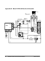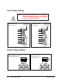
1
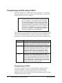
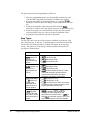
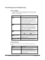
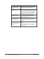
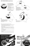
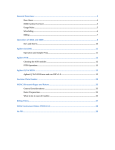
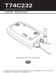
HeatWave Labs, Inc. HeatWave Labs Model 101303-22 Temperature Controller S/N BG10184 User’s Manual Important Safety Notice This instrument operates from and delivers potentially lethal voltages. Observe all precautions when using this device, and particularly be sure that all devices connected to the instrument are safely wired and properly grounded. Always disconnect power to the instrument before opening the enclosure or making any wiring changes. Additionally, this device is intended to control heaters and thermal systems, which may be hot and/or dangerous. Beware that damage to heaters and other equipment, possibly resulting in personal injury or death may result from improper use or control of thermal systems. Understand the safety implications of your system and take proper precautions to avoid damage to property or injury to personnel. Where to Get More Information This owner’s manual represents the most current information at the time it was published; for the latest information, please visit our website: www.cathode.com. We may also be reached in the following ways: HeatWave Labs, Inc. 195 Aviation Way, Suite 100 Watsonville, CA 95076-2069 Tel: 831-722-9081 Fax: 831-722-5491 Email: [email protected] Warranty and Repair Information Our products are warranted against defects in materials or workmanship according to our Standard Product Warranty, TB-166. Model 101303-22 Important Safety Notice i Model 101303-22 Specifications • Ramp and soak programmability with storage for 2 profiles, with up to 8 steps per profile • Autotuning PID control; also supports manual tuning and other control modes, including alarm mode • Solid-state control utilizing an oversized solid-state relay for long-life and precise control • Phase-angle fired SCR for use with tungsten heating elements • Inductively coupled load for use with 8, 16 or 32 volt loads. See Factory Configuration in Appendix A. • Over-temperature protection utilizing a separately controlled alarm setpoint and an independent mechanical relay in series with the solid state control relay • Internal SCR is short-circuit protected by a back-panel accessible semiconductor fuse (HWL p/n 101960-01, FWH020A6F) • Over-current protection using a front panel circuit breaker ii Model 101303-22 Specifications • Open loop protection, shutting down output if open loop operation is detected. See Factory Configuration in Appendix A. • Dual LED displays on control module for simultaneous indication of process temperature and setpoint in Fahrenheit or Celsius (default) • Input power: 100-130 VAC, or 230/240 VAC, 50/60 Hz. See Factory Configuration in Appendix A • Output power: • See Factory Configuration in Appendix A • Display resolution: 1° • Absolute accuracy: ±1° • Heater connector: 3-pin screw terminal, including ground conductor • Type K thermocouple sensor input • range: 0 to 1370°C • ambient rejection: <0.1°C/°C • connector: standard Type-K • Enclosure: standard EIA 19” EIA rackmount, 7.0” tall (5 rack units), 14” deep, 44 lbs. • Ambient temperature range: 0 to 60°C, non-condensing Model 101303 Table of Contents Important Safety Notice .......................................................................................... i Where to Get More Information .............................................................................. i Warranty and Repair Information............................................................................ i Model 101303-22 Specifications............................................................................ ii Overview ................................................................................................................ 2 Displays and Menu Navigation .............................................................................. 2 Getting Started ....................................................................................................... 4 Programming and Executing Profiles..................................................................... 8 Programming a Profile....................................................................................... 8 Step Types .................................................................................................... 9 Running a Profile ............................................................................................. 10 Resuming a Halted Profile............................................................................... 10 Using the Wait-for Process Deviation Function............................................... 10 Advanced Features and Settings......................................................................... 11 Setting the autotune point to a lower value ..................................................... 11 Switching between Celsius and Fahrenheit .................................................... 11 Changing the resolution (decimal point).......................................................... 11 Power limiting .................................................................................................. 12 Other features.................................................................................................. 13 Error Messages and Troubleshooting.................................................................. 14 Error messages ............................................................................................... 14 Troubleshooting ............................................................................................... 14 Appendix A: Factory Configuration ..................................................................... 16 Appendix B: Model 101303-22 Electrical Schematic .......................................... 18 Model 101303-22 Model 101303-22 Specifications iii Overview The HeatWave Labs Model 101303-22 is a full featured, high quality rackmount temperature controller designed for low-voltage tungsten heater control applications requiring precise, reliable control and ramp/soak programmability. Over-temperature protection is provided by an adjustable alarm that uses the control sensor as input. The alarm will disable power to the heater if the alarm setpoint is exceeded. Alarm switching is provided by an independent, internal mechanical relay in series with the solid-state control relay. This alarm scheme provides protection against system runaway if the solid-state relay should fail in the closed position. In addition to over-temperature protection, the Model 101303-22 provides other mechanisms like open loop and open sensor detection to assist in system protection. The phase-angle fired SCR is protected by a semiconductor fuse that can be replaced via back-panel access. Caution: An independent sensor is not used for the alarm scheme in the Model 101303-22. Be aware that some failure modes and resulting runaway can go undetected in a system that does not use an independent alarm sensor. 2 Overview Model 101303-22 Displays and Menu Navigation The Watlow® Series 96 Controller with the ramping software option allows programming of 2 temperature vs. time profiles (called “files) that can each have up to eight distinct steps programmed into them. Upon power-up, the unit starts at the “Home Page” and indicates the process temperature in the upper display and the setpoint (or ) in the lower display. While not running a profile, the setpoint can be directly adjusted with the up and down arrow keys. The setpoint is registered about 2 seconds after the last pressing of either up or down arrow. Management, programming, and execution of temperature vs. time profiles are explained in the Programming and Executing Profiles section. LEDs 1 to 4: 1. Illuminated when heater output is active. For example, it will be on continuously when the heater is at 100% power, and on half the time when the heater is at 50% power. 2. Not used. 3. Illuminated when the over-temperature alarm has been activated. 4. Not used. Upper Display: Indicates process temperature, or parameter value when in menus. Lower Display: Indicates process setpoint, or parameter name when in menus. Advance Key: When at the home page, pressing this key will open the programming menu. If in other menus, this key selects the menu choice in the upper display, scrolls through menu selections, or will scroll through parameter values in the lower display. Profile Indicator: Illuminated when controller has been set to manual mode, where Upper Display indicates percent output. Up and Down Keys: Pressing up or down alone changes the setpoint or parameter value. Pressing them simultaneously for 3 seconds accesses Operations Page. If held for 3 more seconds, accesses Setup Page. See Watlow Series 96 User’s Manual for full description of Operations and Setup Pages. Infinity/Home Key: From the home page, pressing once opens the Pre-run menu; pressing again starts the profile and opens the Run menu. If not at the home page, pressing this key will exit the menu system and return to the home page. Figure 1 Control module keys and displays 3 Displays and Menu Navigation Model 101303-22 Getting Started Getting started using your new HeatWave Labs Temperature Controller should be quick and easy. The Error Messages and Troubleshooting section of this manual describes errors that may be encountered during this process. For more details about the operation of the control module, consult the attached Watlow® Series 96 user’s manual. This manual is also available for download at the HeatWave labs web site, www.cathode.com or at http://www.cathode.com/pdf/series96man.pdf. To ensure the quickest and most reliable startup, please follow the eight steps below in the order shown. 1. Unpack the instrument Be sure that you received the following items in good condition. If there was any damage in shipping, please keep your shipping containers and contact the factory immediately. • Model 101303-22 instrument chassis • Power Cord • HeatWave Labs p/n 101960-01 (FWH-020A6F) 20A, Fast Acting Semiconductor Fuse (Installed) • Manuals: HeatWave Labs Model 101303-22 and Watlow® Series 96 user’s manuals • HeatWave Labs Catalog 2. Connect the instrument Warning: This instrument is designed for use with input voltage, current and frequency as specified in the Factory Configuration in Appendix A only; serious equipment damage and/or injury will occur if it is connected to improper power. Caution: Air vents are located on top, bottom and rear of the instrument. Air flow must not be restricted at these locations. 1. Make sure the switch on the front panel is in the off position. 2. Plug your process thermocouple, Type K, into the control sensor receptacle on the rear panel. (If you need to add a connector to your sensor, do it now. Remember thermocouples are polarity sensitive, for Type-K the yellow wire is positive.) 4 Getting Started Model 101303-22 Warning: This unit is designed to deliver maximum output voltage and amperage to the load at 100% controller output. If the load is designed to run at lower than the maximum output capability, the controller must be adjusted to limit the voltage to this load. The factory has limited the output of this controller as per the controller settings listed in the Factory Configuration in Appendix A. It is likely that the user will need to change these settings to reach desired operating temperatures and ramping rates. Consult the Series 96 Manual for necessary settings. 3. Plug the unit into a power receptacle. 4. Do not connect the system heater at this time. Warning: This instrument is designed for use with input voltage, current and frequency as specified in the Factory Configuration in Appendix A only; serious equipment damage and/or injury will occur if it is connected to improper power. 3. Power up the instrument 1. Turn the instrument on using the front panel switch. 2. After a few seconds the sensor temperature will be visible in the upper display of the control module (in Celsius) and the setpoint will be visible in the lower display. Verify that this sensor temperature appears reasonable. 5 Getting Started Model 101303-22 4. Set over-temperature alarm set point The over-temperature alarm setpoint must be set. For more information on operating the user interface, see Displays and Menu Navigation above. Note: The module will exit the menu system and return to the main display in 60 seconds if no keys are pressed. If the control sensor reaches this setpoint for any reason the heater output will be shut off until the user resets the instrument manually (by pressing the infinity key after the temperature has dropped more than 2 °C below this alarm limit). 1. Press and hold the up and down arrow keys simultaneously for 3 seconds to enter the Operations Page ( will appear in the lower display). 2. Scroll up or down with the arrow keys until appears in the upper display. 3. Press the blue advance key twice, or until the upper display reads . 4. The controller alarm setpoint may now be set with the arrow keys. 5. Return to the main display by pressing the infinity key. 5. Set the setpoint 1. The setpoint can be adjusted using the up and down arrow keys from the home page (not while inside any other menus). At this point, adjust the setpoint to a value below the current process temperature to avoid applying power to the output. The lower display shows if the setpoint is adjusted to its lowest permissible value (0° C). 6. Verify proper system performance 1. If your system will be damaged by 100% output power, set the power limits on the control module as described in the Advanced Features section. In Appendix A, the Power Limit Parameters factory preset is shown. 2. Turn the unit off, plug in the heater, and turn the unit back on again. 3. Set the setpoint a few degrees above the present process temperature so that output power will be applied. Verify that: a. LED #1 illuminates or begins to flash intermittently, indicating heater output is activated, and b. The temperature begins to rise. 4. If the system temperature does not begin rising, shut off power and investigate sensor and heater connections and integrity. If the circuit breaker trips, or any errors are displayed, refer to the Error Messages and Troubleshooting section of this manual. Watlow is a registered trademark of Watlow Electric Manufacturing Co. 6 Getting Started Model 101303-22 7. Autotune the system Excellent thermal control is normally attained by automatically tuning the control parameters (described below) to the specific thermal system. The controller should be autotuned the first time it is used and whenever the thermal properties of the system being controlled change significantly. Notes: For systems that cannot tolerate the overshoot that can occur during the autotuning process, change the ATSP parameter (as described in the advanced features) to a lower value so that the system autotunes around a lower value. The default autotuning point is 90% of the setpoint. This may also be set to 100% to tune the controller at the setpoint if your system allows. Be aware that the autotuning algorithm turns power on at 100% to measure system response. Operating at 100% duty cycle may damage some types of heaters, especially those used in high temperature furnaces. Do not autotune the system if it will be damaged by 100% output power. If this is the case, refer to the Watlow® Series 96 manual for the manual tuning procedure. 1. Set the control setpoint to a safe operating value for your system. 2. Press the two arrows keys simultaneously until appears in the lower display. 3. Scroll up or down with the arrow keys until appears in the upper display. 4. Press the blue advance key once to select this user menu. 5. Press the blue advance key once or until is displayed in the lower display of the control module. Use one of the arrow keys to change the upper display from to . 6. Press the infinity key to return to the main display and initiate the autotune sequence. The upper display will flash alternately with the temperature until it is done autotuning. This process typically takes from a few minutes for small systems to over an hour for larger systems. 8. Verify safe alarm conditions Your temperature controller is now configured for your system and ready to use. During normal operation, the current process temperature will be visible in the upper display and the setpoint temperature in the lower display. If the over-temperature alarm setpoint is exceeded (optional feature), the message will flash in the upper display and heater output will be disabled. This alarm can be cleared by pressing the infinity key after the process temperature has fallen more than 2 °C below the alarm setpoint. 7 Getting Started Model 101303-22 Programming and Executing Profiles This section outlines how to manage and execute temperature vs. time profiles. Detailed explanation of the menu structure and profile parameters can be found in the Watlow® Series 96 User’s Manual. Note: The default settings of the HeatWave Labs Model 101303-22 allow for only a subset of step parameters that are available in the Watlow Series 96 Controller. For example, by default, the “program type” parameter found in the Global Menu is set to “time based”, which means setpoint steps are specified in time durations as opposed to being specified as a ramp rate in degrees per unit time. In addition, event inputs and outputs are not used. Therefore, the event handling functions and “wait for event” features are not implemented. Three menus are used to manage and execute profiles: the Pre-run Menu, the Run Menu, and the Programming Menu. They can be accessed from the Home Page of the system. The Home Page is essentially the main display, where process temperature and setpoint are displayed, and when the unit is not in another menu. Menu Function Programming Allows the user to program the steps that are stored in the two profiles. Use the blue Advance key to scroll through parameters and press the Infinity key to exit the menu. Pre-Run The Pre-Run menu allows the user to select a file and step number from which to begin execution, or to resume a previously halted profile. Enter the Pre-Run menu by pressing the Infinity key from the Home Page. Scroll through the menu using the blue Advance key. While in the Pre-Run menu, the Profile Indicator will be flashing. Run The Run menu is available while a profile is running, allowing the user to view the setpoint and time remaining for the currently running step. Enter the Run menu (and start the selected file and step) by pressing the Infinity key from the Pre-Run menu. Scroll through the menu using the blue Advance key. While in the Run menu, the Profile Indicator will be continuously illuminated. Programming a Profile Two separate and distinct profiles, each containing up to eight steps may be stored in the controller. The step type can be any one of four step types available: set point step, soak step, jump loop step, or end step. Various parameters will need to be specified for each step, the number and types of which will depend on the step type chosen. 8 Programming and Executing Profiles Model 101303-22 The general procedure for programming a profile is to 1. Enter the programming menu by pressing the blue Advance key once from the Home Page while the program is on hold or not running. 2. Select the file number by choosing number 1 or 2 while the parameter is shown in the lower display, and pressing the blue Advance key. 3. Select the step number within the selected file while the parameter is visible in the lower display, and press the blue Advance key. 4. Select the step type (as described below) for each step in the profile. After specifying a step type, select type-specific parameter values. 5. Repeat above procedure for each step in the profile. Step Types The step type can be any one of four step types available: set point step, soak step, jump loop step, or end step. Various parameters will need to be specified for each step, the number and types of which will depend on the step type chosen. The purpose of each step type and the parameters that need to be specified are detailed below. Step Type Set Point Step: ramp to a setpoint in a specified amount of time Soak Step: remain at a setpoint for a specified amount of time Jump Loop Step: allows for jumping and looping to other steps in either of the two profiles End Step: specifies end of profile and the state of control when the profile is ended 9 Programming and Executing Profiles Available Parameters Set point value (0 to 1370°C) Hours (0 to 99) Minutes (0 to 59) Seconds (0 to 59) Hours (0 to 99) Minutes (0 to 59) Seconds (0 to 59) Wait-for deviation value (if a value is entered, the profile will wait until the process values falls within the range defined by the setpoint ± this value) Jump File (1 or 2) Jump Step (1 to 8) Jump Count (0 to 255): the number of time the jump is to be executed; a value of zero specifies an infinite loop End state ( or ): If is selected, the controller will maintain the same setpoint as that specified in the previous step. If is selected, the controller output is set to zero and is shown in the lower display. Model 101303-22 Running a Profile The user can start executing a program at any step within either profile. To run a profile: 1. Enter the Pre-Run menu by pressing the Infinity key once from the Home Page (while a profile is not already running). The Profile Indicator will begin flashing. 2. The upper display shows the file number to be run and is shown in the bottom display. Use the up and down arrow keys to select which file number to run. 3. Press the blue Advance key to accept the file number and advance to the step selection. 4. Use the arrow keys to select the step number at which to begin running the profile. 5. Press the Infinity key and the profile will begin executing from the specified step, and the Profile Indicator will change from flashing to continuous illumination. 6. You may view the currently running step parameters by pressing the blue Advance key multiple times. 7. To stop the profile, press the Infinity key when the profile is running. Resuming a Halted Profile If no changes are made to the profiles after a profile has been halted, the profile can be resumed from the same step from which it was halted. To resume the halted profile: 1. Press the Infinity key once to enter the Pre-run Menu. 2. Press the blue Advance key twice until appears in the lower display. The upper display will show the file and step number at which the profile was halted and will be resumed. Note the parameter only appears in the Pre-Run menu if a profile had been previously halted. 3. Press the Infinity key to resume the profile. Using the Wait-for Process Deviation Function For each soak step in a profile, a Wait-for Process Deviation value ( ) can be entered. If a value is entered, the controller will wait until the process value falls within the deviation band defined by that step’s setpoint value ± the Waitfor deviation value. The controller will begin decrementing the time left in that step only after the Wait-for condition has been met, and will continue to do so regardless of the condition or process changes during the remainder of the step. 10 Programming and Executing Profiles Model 101303-22 Advanced Features and Settings There are numerous advanced features supported on the control module that may be useful in specific circumstances. The most common ones are listed below. Consult the Watlow® Series 96 User’s Manual for more details on these and other options. Setting the autotune point to a lower value 1. Press the two arrows keys simultaneously until appears in the lower display 2. Use the arrow keys to scroll until appears in the upper display. 3. Press the advance key once to select this user menu. 4. Press the advance key three times or until appears in the lower display. 5. Use the arrow keys to adjust the value (in the upper display) to the desired percentage of setpoint at which to autotune. For example, if is set to 80, and the setpoint is set to 750 degrees, it will autotune at 600 degrees. 6. Press the infinity key to return to the main display. Switching between Celsius and Fahrenheit The instrument is shipped with each module configured to display temperature in Celsius. To change to Fahrenheit or back to Celsius: 1. Press the up and down arrows simultaneously. After three seconds the word will be visible in the lower display. Continue pressing both keys until appears in the lower display 2. Use the arrow keys to scroll through the parameters until the upper display shows . 3. Press the advance key to select the global menu. 4. Press the advance key twice, until the lower display reads . Use the arrow keys to select either or . 5. Press the infinity key to return to the main display. Changing the resolution (decimal point) The instrument can be configured to display tenths of a degree, but the maximum temperature that can be reached is 1000 degrees. To change the resolution: 1. Press the up and down arrows simultaneously. After three seconds the word will be visible in the lower display. Continue pressing both keys until appears in the lower display 11 Advanced Features and Settings Model 101303-22 2. Use the arrow keys to scroll through the parameters until the upper display shows . 3. Press the advance key to select the Input 1 menu. 4. Press the advance key five times, until the lower display reads and the upper display reads 0.0. Use the arrow keys to toggle this to 0. 5. Press the infinity key to return to the main display. Power limiting Some heaters, especially those used in furnaces, must be controlled quite carefully. Heaters with a negative temperature coefficient of resistance may be damaged if operated at full power at low temperatures. Metal film radiative heaters may not tolerate large duty cycle at high temperatures. The Model 101303-22 allows for two independent power limits and a temperature breakpoint to be set. Warning: This unit is designed to deliver maximum output voltage and amperage to the load at 100% controller output. If the load is designed to run at lower than the maximum output capability, the controller must be adjusted to limit the voltage to this load. The factory has limited the output of this controller as per the controller settings listed in the Factory Configuration in Appendix A. It is likely that the user will need to change these settings to reach desired operating temperatures and ramping rates. Consult the Series 96 Manual for necessary settings. To enable power limiting: 1. Press the up and down arrows simultaneously. After three seconds the word will be visible in the lower display. Continue pressing both keys until appears in the lower display 2. Use the arrow keys to scroll through the parameters until the upper display shows . 3. Press the advance key to select the global menu. 4. Press the advance key five times, until the lower display reads . Use the arrow keys to adjust the upper display to the desired temperature breakpoint where the controller will switch to the power limits set below. 5. Press the advance key once so that the lower display shows . Use the arrow keys to select the power limit, in percent, for temperatures above the temperature breakpoint set in step 4. 6. Press the advance key once so that the lower display shows . Use the arrow keys to select the power limit, in percent, for temperatures below the temperature breakpoint set in step 4. 12 Advanced Features and Settings Model 101303-22 7. Press the infinity key to return to the main display. Caution: The autotune algorithm overrides these power limits during its execution. Do not autotune your system if it can be damaged by 100% duty cycle. Other features There are number of other features which are supported on the controller, but are typically only useful under very special circumstances. These are described briefly here. Please consult the Watlow® Series 96 user’s manual for more information. Caution: There may be subtle intricacies and implications for system operation when implementing these advanced features. These alternate modes are not recommended except for use by expert users in special applications. 1. Bumpless Failure Mode: the controller output may be configured to keep outputting a fixed percent power rather than shutting off after a sensor fault. 2. Additional alarm configurations: The over-temperature alarm may be configured to be non-latching (default is latching, meaning it must be manually reset even when the process is back in the safe region). The alarm may be configured to be two-sided, silenceable (ability to be overridden), and/or triggered by a deviation from setpoint. These other alarm modes should be very well understood before being implemented and are not recommended for general use. 3. Calibration: Sensor input and analog output may be manually calibrated to change offsets or gains. This is rarely necessary since incorrect offsets and scaling are almost always caused by improper grounds, faulty wiring, or other pathological problems. The controller should not be recalibrated unless it is certain that there are no other problems. 4. PID parameters: PID parameters may be manually adjusted. Note that control can rarely be improved upon, and danger of adversely affecting control performance is eminent. 13 Advanced Features and Settings Model 101303-22 Error Messages and Troubleshooting Error messages The control module is capable of displaying a number of errors and alarm conditions. These messages are described below. For more details, consult the Watlow® Series 96 Manual. Message Meaning and Corrective Action flashing in upper Recorded process temperature has exceeded alarm limit (over-temperature setpoint). Check value of alarm limit and integrity of sensor. When the process temperature falls more than 2 °C below the alarm limit, clear the error by pressing the reset key. Alternatively, this alarm may be cleared by cycling power to the instrument once the process temperature has fallen below the alarm limit. flashing in upper Open loop error. The controller has been outputting 100% power but its sensor temperature is not changing. Verify that the sensor is located properly and that the heater is connected and functioning properly. This error is cleared by cycling power to the unit. This error indicates a thermal system malfunction -- do not ignore it! flashing in upper System is autotuning (this only occurs when initiated manually by the user). No action is necessary, although autotuning sequence may be terminated by setting parameter to in main menu. , , or in upper display Sensor errors. Verify sensor connections and continuity. Unit will continue to display error condition until power is cycled or error is cleared by pressing the infinity key display display display , through upper display in Internal module errors, not normally seen. Cycle power to unit, and if problem persists call factory. Troubleshooting Below are some tips to resolve problems not identified by the standard error messages: 14 Symptom Possible causes Displayed temperature goes down when heaters turn on. Thermocouple leads reversed. Shut off power immediately and check wiring of sensor. Circuit Breaker trips Check that heater is sized properly. The Model 101303-22 will not deliver more than 15 Amps. Check that the heater power is not shorted to ground anywhere in the system. Error Messages and Troubleshooting Model 101303-22 15 Symptom Possible causes Heater never heats; open loop errors cannot be avoided. Check that heater is sized properly. If so, internal transformer may have failed. Call factory. Over-temperature alarm will not clear. This alarm limit has a two-degree hysteresis. The process temperature must fall more than 2 °C below the alarm set point before it can be cleared with the reset key. This hysteresis may be overridden by cycling power to the instrument once the process temperature has fallen below the alarm limit. Temperature fluctuates by more than 1 degree. Verify the unit has been autotuned in the current thermal configuration and near the setpoint temperature. If not do so. Unit does not control. It heats regardless of setpoint, until alarm limit trips. The solid-state relay may have failed. This is unlikely unless the output has been shorted and the semiconductor fuse did not properly function (blow). Call factory. Control module does not display anything, or displays but is not functioning properly. Check that circuit breaker is on, and line voltage is present. If so, disconnect power, remove cover, and ensure all connectors on the back of the control module are securely in place. Error Messages and Troubleshooting Model 101303-22 Appendix A: Default Factory Configuration If for any reason the instrument settings become corrupted, the instrument must be reconfigured with the values listed below. Additionally, it will then be necessary to reset the setpoint, alarm limit, autotune the controller, and reset any other advanced configurations that have been changed for your system. Refer to the Watlow® Series 96 User’s Manual for more information. Warning: This unit is designed to deliver up to 16 Volts and 94 Amps to the load at 100% controller output. If the load is designed to run at lower than 16 Volts, the controller must be adjusted to limit the Voltage to this load. The factory has limited the output of this controller as follows: Power Limit Set Point (PLSP) 300°C Power Limit Above (PL A) 50% Power Limit Below (PL B) 35% It is likely that the user will need to change these settings to reach desired operating temperatures and ramping rates. Consult the Series 96 Manual for necessary settings. Table A1: Power input and output (Load) settings This unit can be internally configured by the factory for 120VAC or 240VAC and 50 Hz or 60 Hz input. The output can be set to 32V/47A, 16V/94A or 8V/94A. This unit has been configured at the factory as follows: I/O Setting Units Value Input Voltage Output Voltage Output Current Line Frequency Volts, AC Volts, AC Amps, AC Hertz, Hz 120 16 94, max 50 or 60 Table A2: Control Module Settings 16 Menu Location Parameter Value Oper>ALM Set>glbl Set>glbl Set>glbl A3hi C_F Err Fail 1000 C Lat Off Appendix A: Default Factory Configuration Model 101303-22 17 Menu Location Parameter Value Set>glbl Set>glbl Set>glbl Set>glbl Set>InP1 Set>InP1 Set>Out1 Set>Out3 Set>Out3 Set>Out3 PLSP PL A PL B OPLP In 1 Dec1 Prc1 Ot 3 Lat3 Sid3 300C 50% 35% Off H 0.0 4-20 Al Yes Hi Appendix A: Default Factory Configuration Model 101303-22 Appendix B: Model 101303-22 Electrical Schematic L1 L2 L1 L2 Gnd semiconductor fuse: 20 Amp H4 H3 Solid State Phase + + ControlOut Out Output OutputControl - 24VAC power 24VAC power Output 1 4-20 mA Control Module 13 Red 14 Output 1 Contr ol Module11 Black Output 3 12 Input 1 6 13 Red/White Input 1 AC Power 7 8 6 Output 3 7 9 AC Black Pow er 11 14 9 Black Yellow Black X1 Black 120VAC Black Jumpers Very fast-acting semiconductor fuse: 20 Amp Black Bussmann p/n FWH-020A6F 1 8 1 24VAC coil 3 4 120VAC White White Black Sensor receptacle X2 24V transformer Red/ White 120VAC Grey Blue 6 Mechanical Relay 44 10 12VAC 120VAC 12VAC 120VAC 24V transformer Orange White 5 6 7 Brown 8 Black Black Mechanical Relay Black Black Sensor receptacle X3 2 4- 20 mA White - + 120VAC 120VAC X4 Red 12 - + - H1 9VA C 18VAC +Control +Control Signal - Signal -Phase H2 16VAC 16VAC Solid State AT Firing Card Relay Relay Outlet Outlet Receptacle Note: 16V output / 120V input configuration Very shown fast-acting AT Firing Card Gnd 0 6 Black Black Inlet rec eptacleInlet receptacle 120VAC 120 or 240VAC Black G Front panel H N circuit breaker Front panel circuit breaker H G N White 18 Appendix B: Model 101303-22 Electrical Schematic Model 101303-22 Input voltage settings Caution: Input and output voltages can be changed with internal transformer tap settings. The information below is for reference only and to be done only by the factory or qualified technician. For 120V operation: jumper 1 to 2, 3 to 4, 5 to 6, and 7 to 8. Switched output from controller (switched 120VAC) For 240V operation: jumper 2 to 3 and 6 to 7 ONLY. Switched output from controller (switched 240VAC) Jumpers Jumpers X1 Black 1 X1 Black 1 X3 X3 2 2 X2 X2 3 3 X4 X4 4 4 Orange White Brown Black Orange 5 White 6 White Brown 7 Black 8 Black 5 White 6 7 8 Black Neutral Neutral 240VAC 120VAC Output voltage settings For 32V output: connect H1 to L2, and connect H4 to L1, and connect H2 to H3 For 16V output: connect H1 and H3 to L2, and connect H2 and H4 to L1 L1 L2 Gnd L1 L2 Gnd Outlet H4 H3 16VAC 120VAC X4 19 Input voltage settings X3 H2 H1 Outlet H4 120VAC 120VAC X2 H3 16VAC 16VAC X1 X4 X3 H2 H1 16VAC 120VAC X2 X1 Model 101303-22