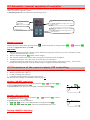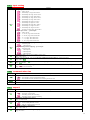
1
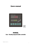
Users manual
Ht40B
PID controller
LAC, spol. s r.o.
Ht40B, 01/03, soft 4.11/rev. 1 english
version
Štefánikova 116
664 61 RAJHRAD
e-mail: [email protected]
www.lac.cz
1
1 Important
Ht40B is a temperature / process controller intended for the built-in to panel. The format of controller is 96 x 48 mm
(1/8 DIN).
The scope of the controller:
• controlling of stp value,
• controlling Master – Slave (1 controller is supervisory MASTER, the others are SLAVEs – receive stp value),
• cascade controlling (it is used in systems with long lag times).
The controller can be equipped with 1 input:
• temperature (thermocouples + rtd sensor -Pt100),
• process (0-20mA, 4-20mA, 0-5V, 1-5V, 0-10V),
3 outputs:
• control (heating control),
• auxiliary (cooling control, signalling),
• alarm,
and communication lines:
• RS-232, protocol MODBUS RTU,
• EIA-485, protocol MODBUS RTU.
The controller is easy to run and operate. The parameters set can be locked and thus preventing from deleting by a user.
User manual for the controller Ht40B is divided into the particular chapters. When you install and put it into operation we
recommend proceeding in the following way:
If you are a final user, the controller is in the default setting by the suplier
If you are a final user, you will get the device in the customized setting and you can view and change only the parameters that
you need for your own work on the controller.
If you are a new user of the device, focus on the following chapters:
•
•
•
Basic terms, here it is explained the key functions, displays, and so on….
Basic mode, the description of basic mode of controller.
User level, in this chapter you will find the information on the parameters accessible for a user and the information on the
basic features of the controller.
If you are carring out the complete installation and setting of the controller
In this case you proceed in accordance with the following chapters:
• Installation, in this chapter it is described how to build in a controller into panel.
• Principals of installation, we recommend you to observe the guidelines described in this chapter.
• Wiring, the description for wiring of the controller.
• Putting into operation, at first power-up you enter the initial menu in which you can configure and set the most important
parameters of controller.
According to the procedure you will perform installation, wiring and basic setting of controller. You can find out more details
on the scope of the controller and its operation in the following chapters.
For the users who have the controller completely set, we recommend to perform the setting of all
the parameters in service level, menu ConF. Initial password for the entry to service level is set to 995.
2
2 Basic terms
To avoid problems in operation of device the user should be able to manage its operation, setting parameters, ...
2.1 Operation and description of controller
On the front panel board you can see 2 displays, 3 control lights (LED diodes) for indicating a status of outputs. The device is
set and configured via 4 key-buttons.
Function of indicators
Upper display:
• Indicates procees value in
Basic mode
• When set, it shows parameter
value
Lower display:
• Indicates stp value in
Basic mode.
• When set, it shows the type
of parameter
LED diode „Al“
Indicates the state of alarm output
LED diode „2“
Indicates the state of output 2
LED diode „1“
Indicates the state of output 1
Function of key-buttons
The setting of parameters of the controller is performed via key-board. The function of each key-button is as follows:
•
, key for setting and viewing of parameters of user, operation, configuration and user level. By pressing this key you
confirm the change in configured parameter and the controller comes to another parameter.
•
, key for decreasing a value of parameter. The value of parameter is either the figure or abbreviation composed of
maximum 4 letters.
•
, key for increasing a value of parameter.
•
, key for switching between automatic and manual operation, see page 8.
2.2 Information and error messages
Information and error messages are indicated only in basic mode, see page 5.
Information messages, upper display
•
----
… error of input sensor or input is not set.
Information messages, lower display
Information messages on lower display blink, they can be:
• Man … the controller is in manual operation, the output power is set by a user.
• rAMP … indication of ramp function.
• CSCd … indication of cascade controlling.
• Aut1 … starting autotunning of PID set 1 of the output 1, Pb1A, It1A, dE1A.
• Aut2 … starting autotunning of PID set 2 of the output 1, Pb1b, It1b, dE1b.
• Aut3 … starting autotunning of PID set of the output 2, Pb2A ,It2A ,dE2A.
3
Error messages, lower display
If there is a error message indicated then the control outputs are switched OFF, the signal output is switched OFF, the alarm
output is activated.
• Err0 … error in FLASH memory of program. Switch the controller OFF and ON again. If the problem persists, contact
your supplier.
• Err1 … error in EEPROM memory for configuration and operation parameters. The troubleshooting error can be made
by restarting of all parameters in service level. After restart it is necessary to set up all parameters again. This can be done
only by an experienced user. If the trouble persists, contact your supplier.
• Err3 … error in A/D converter. It can be caused by electrical impulse at input, too low temperature and excessive
humidity, … . Switch the controller OFF and ON again. If the problem persists, contact your supplier.
2.3 Overview of levels, menus
For the right function of the controller it is necessary to set up its parameters properly. For better understanding the parameters
are sorted out to groups (levels and menus). Level is superior to menu, menu is a part of level (menu out1).
The structure of sorting shows the following picture.
User level
Enables the quickest access to chosen parameters. For this level you can choose
parametrs from operation level and make them accessible for a user.
Switching over between automatic and manual operation
By double pressing the keys you switch the controler between automatic and
manual operation. This function must be allowed in configuration level.
Double press
for 3 seconds
Choose requisite
level by arrowkeys.
oPEr
x
LEVL
PASS
ConF
x
LEVL
PASS
Operation level
The level where the operation parameters find themselves.
Configuration level
Is intended for the configuration of the controller.We recommend to secure this
level with password.
SErV
x
LEVL
PASS
If there is no password set for the
particular level, parameter PASS will
not apear.
4
Service level
Is intended for service level.We recommend to secure this level with password.
3 Basic mode
The controller is in Basic mode when powered up (the initial set-up must be performed, see page 27 ).
On upper display process value is shown, on lower display there can be stp value or heading oFF
(at Master / Slave controlling, if the controller does not receive stp value).
On upper display process
value is shown
On lower display stp
value is shovn
or it
shows oFF
•
•
•
•
•
•
When controlling to stp value there is stp value shown on lower display.
When in Master / Slave controlling (the controller is Slave) there is stp value shown on lower display. If the controller
does not receive stp value and switching OFF is set for the output, on lower display heading oFF is lit and the control
output is switched OFF.
When in cascade controlling there is calculated stp value shown on lower display and heading CSCd blinks.
When in manual operation there is output power in % shown on lower display and heading Man blinks.
If there is any other heading on lower display, the controller is not in basic mode, parameters are set or viewed.
Information and error messages are indicated only in basic mode.
Return to basic mode
•
•
To return to basic mode press shortly the keys
.
If there is no key pressed for 60 seconds, the controller itself returns to basic mode.
5
4 User level
User level is intended for the quick access to the most common parameters for a user.
To enter user level and to go through this level press the key
.
To return from user level you must go trough all the parameters or by pressing shortly the keys
.
You can configure freely the structure of user level:
• you can define which parameters and menus will be in user level,
• you can define on which position these parameters(menus) will be placed,
• the parameters and menus are displayed only in case that their showing has the meaning (e.g. the parameters of controlling
are shown only in case that output is set as the control output).
Overview of all the parameters and menus of user level
Display
PCn1
PCn2
AoFF
Aut
L-r
dIF
CdLo
CdhI
Pb1A
It1A
dE1A
Pb1b
It1b
dE1b
hYS1
Pb2A
It2A
dE2A
hYS2
o2Lo
o2hI
6
Procedure
Indicates the power in % of the control output 1. It is displayed only then if the output 1 is set as the control output.
Indicates the power in % of the control output 2. It is displayed only then if the output 2 is set as the control output.
Menu for switching OFF of permanent alarm. Set YES and confirm to switch OFF the permanent alarm.
Starting / ending of autotunning/automatic setting of PID parameters:
•
oFF, autotunning /automatic setting of PID parameters is turned OFF.
•
ht, starting of autotunning/automatic setting of PID parameters for heating
•
CL, starting of autotunning/automatic setting of PID parameters for cooling.
Selection for setting of stp value:
•
L, stp value is local (it is set in the controller).
•
M-S, remote setting of stp value via communication line, it is used for system Master-Slave.
• CSCD, remote setting of stp value via communication line, it is used for cascade controlling.
Difference of remote stp value for system Master-Slave.
Range: -499 to 499 °C.
Low limit range of remote setting stp value for cascade controlling.
Range: -499 to CdhI °C.
High limit range of remote setting stp value for cascade controlling.
Range: CdLo to 2499 °C.
Proportional band of the output 1, the first set of PID parameters.
Range: 1 to 2499 °C.
Integral value of the output 1, the first set of PID parameters.
Range: oFF, 0.1 to 99.9 minutes.
Derivative value of the output 1, the first set of PID parameters.
Range: oFF, 0.01 to 9.99 minutes.
Proportional band, the second set of PID parameters.
Range: 1 to 2499 °C.
Integral value, the second set of PID parameters.
Range: oFF, 0.1 to 99.9 minutes.
Derivative value, the second set of PID parameters.
Range: oFF, 0.01 to 9.99 minutes.
Hysteresis of the output 1, this single parameter is set only for ON/OFF control.
Range: 1 to 249 °C.
Proportional band of the output 2.
Range: 1 to 2499 °C.
Integral value of the output 2.
Range: oFF, 0.1 to 99.9 minutes.
Derivative value of the output 2.
Range: oFF, 0.01 to 9.99 minutes.
Hysteresis of the output 2, this single parameter is set only for ON/OFF control.
Range: 1 to 249 °C.
Low limit of signalling. Output is activated when process value is lower than the set signalling limit.
Range:
• -499 to o2hI °C for ot2 = SGPr.
• -999 to 0 °C for ot2 = SGdE.
High limit of signalling. Output is activated when process value is higher than the set signalling limit.
Range:
• o2Lo to 2499 °C for ot2 = SGPr.
• 0 to 999 °C for ot2 = SGdE.
ALLo
ALhI
Low limit of alarm. Alarm is activated when process value is lower than the set alarm limit.
Range:
• -499 to ALhI °C for ot3 = ALPr.
• -999 to 0 °C for ot3 = ALdE.
High limit of alarm. Alarm is activated when process value is higher than the set alarm limit.
Range:
• ALLo to 2499 °C for ot3 = ALPr.
• 0 to 999 °C for ot3 = ALdE.
Setting of parameters and menus in user level
User level provides a user with the quickest access for viewing and setting of parameters. The list of the parameters that will be
present and accessible for a user in user level, as well as their sequence, can be freely configured.
You will carry out the formation of user level in configuration level, menu uSEr.
Example how to create user menu:
You want to place on the 1st position in user level the parameter for starting autotunning Aut , on the 2nd high limit of
alarm ALhI. Proceed as follows:
• Set the parameter StP1 = Aut.
• Set the parameter StP2 = ALhI.
• 3rd to 8th positions are not used, for parameters StP3 to StP8 set no.
You can view the result in user level
4.1 Controlling of stp value
When the controller maintains stp value, lower display shows stp value and upper display shows process value. Setting of stp
value can be changed with the arrow-keys, the new stp value is edited after approx.
2 seconds form the last pressing of the key.
Process value
Stp value
Keys for setting of
Stp value
Ramp function
When the controller is powered up, rapid temperature changes appear. If this rapid increase in temperature is not wanted, you
can control the ramp rate to stp value with the ramp function.
Ramp function is OFF
SP1
SP1
Ramp to stp value after the
power up. Ramp function is
turned OFF.
•
•
•
•
•
Ramp function is ON
Ramp by ramp function.
Ramp rate is set with
parameter rAMP.
Scale of ramp function is
[ºC/hour].
Ramp function ensures the reaching stp value SP1 in the linear way.
Ramp function is active only after the controller is turned on and it is ended by reaching stp value SP1.
When ramp function is active, on lower display there is stp value SP1 and blinks rAMP.
Ramp function is set in configuration level, menu SYS, parameter rAMP [ºC/hour].
If parameter rAMP = oFF, ramp function is turned OFF.
7
4.2 Automatic / manual operation of controller
Automatic operation of controlling requires the closed control loop. The user adjusts stp value and the controller regulates the
output power that is supplied to system.
At manual operation the user adjusts the required output power.
Process value is shown on
upper display
You switch between automatic
and manual operation by double
pressing the key „F“
In automatic operation lower display shows stp
value.
In manual operation lower display shows the set
output power in %.
In automatic operation you set stp value with the
arrow-keys.
In manual operation you set the output power in %
with the arrow-keys.
Manual operation
Manual operation is set by double pressing the key
is found in configuration level, menu SYS.
. It must be allowed by setting parameter FKEY = A-M. Parameter FKEY
Important:
•
•
•
•
•
When in manual operation the controller can not influence the output power that is set by a user. The behavior of the
system is then fully under users control.
When in manual operation, Man blinks on lower display.
The controller remains in the chosen mode of operation even after the power interruption.
In manual operation the zero output power is set after the power interruption.
In manual operation the output power is always set in % (0 to 100 for heating, -100 to 0 for cooling, -100 to 100 for
heating and cooling) and even in the case that the output is configured as the ON/OFF output.
4.3 Parameters of the control output, PID controlling
The controller Ht40B can be configured for ON/OFF as well as PID controlling and it enables:
• Heating controlling (the output 1).
• Cooling controlling (the output 2).
• Controlling of heating and cooling (the output 1 and 2).
The description of principals of controlling is found on page 16.
Heating, ON/OFF controlling
ON/OFF controlling of heating is set with the parameter ot1 = ht2. Parameter ot1 is
found in configuration level, menu out1.
In operation level you set hysteresis of ON/OFF controlling, parameter hYS1.
hYS1
SP1
Heating, PID controlling
PID controlling of heating is set with parameter ot1 = ht. Parameter ot1 is found
in configuration level, menu out1.
In operation level you set PID parameters:
• Pb1A, It1A, dE1A, If only 1 set of PID parameters is used (parameter ALGo).
• Pb1A, It1A, dE1A, Pb1b, It1b, dE1b, if both sets of PID parameters are used.
Cooling, ON/OFF controlling
8
SP1
ON/OFF controlling of cooling is set with the parameter ot2 = CL2. Parameter ot2
is found in configuration level, menu out2.
STP value for cooling is put down by the value set with parameter SP2 , that is found
in configuration level, menu out2.
In operation level you set hysteresis of ON/OFF controlling, parameter hYS2.
hYS2
SP1 + SP2
Cooling, PID controlling
PID controlling of cooling is set with parameter ot2 = CL. Parameter ot2 is found in
configuration level, menu out2.
STP value for cooling is put down by the value set with parameter SP2 , that is found
in configuration level, menu out2.
In operation level you set PID parameters:
• Pb2A, It2A, dE2A, PID parameters defines the response of the controller.
SP1 + SP2
4.4 Autotunning – automatic setting of PID parameters
The controller is fitted with the function that sets automatically PID parameters.
Autotunning of PID parameters can be started only when the controller maintains stp value SP1 (parameter
L-r =
L)
Start
of
autotunning
End
of
autotunning
When in autotunning, on lower there are the following headings
blinking:
• Aut1 … the controller adjusts parameters Pb1A, It1A, dE1A
for heating.
• Aut2 … the controller adjusts parameters Pb1b, It1b, dE1b
for heating.
• Aut3 … the controller adjusts parameters Pb2A, It2A, dE2A
for cooling.
Procedure of starting autotunning:
•
•
•
•
Autotunning you can start with parameter Aut = ht (setting parameters for heating) or Aut = CL (setting parameters
for cooling). Parameter Aut you will find in operation level. The control output must be set for PID controlling.
The controller explores the characteristics of system from switching ON/OFF on the output and determines optimal PID
parameters. It can cause an overshoot.
In the course of autotunning on lower display the information messages (Aut1, Aut2, Aut3) blink.
After the autotunning is finished the parameters are edited and the information messages stop blinking.
Important:
Parameters Pb1A, It1A, dE1A, are set when 1 set of PID parameters is used (ALGo = PId) or the both sets of PID parameters
are used (ALGo = 2PId) and the actual set point value is lower than parameter SPId.
• Parameters Pb1b, It1b, dE1b, are set if the actual set point value is higher than parameter SPId when the both sets of PID
parameters are used (ALGo = 2PId)
Parameters ALGo and SPId are found in configuration level, menu out1.
•
9
5 Operation level
In operation level you can set parameters which are available to a user.
From basic mode to operation level you will get by pressing the keys
on upper display set oPEr and confirm with the key
for 3 seconds. On lower display it appears LEVL,
. If PASS appears on lower display the level is secured with the
password. In this case set the right password with the arrow-keys and confirm with the
.
PCn1
Pcn2
AoFF
L-r
dIF
CdLo
CdhI
out1
Pb1A
It1A
Yes
dE1A
no
E
Pb1b
out2
Pb2A
It1b
It2A
Yes
dE1b
dE2A
no
hYS1
hYS2
out3
ALLo
Yes
o2Lo
ALhI
o2hI
no
Menu of operation level
Display
PCn1
Shows the actual power of the output 1 in %.
PCn2
Shows the actual power of the output 2 in %.
AoFF
You can switch OFF permanent alarm by setting
Aut
L-r
dIF
CdLo
CdhI
10
Meaning
YES and confirming.
Starting / turning OFF of autotunning of PID parameters:
•
oFF, turning OFF of autotunning of PID parameters.
•
ht, starting of autotunning of PID parameters, heating.
•
CL, starting of autotunning of PID parameters, cooling.
Selection for setting of stp value:
•
L, stp value is local (it is set in the controller).
•
M-S, remote setting of stp value via communication line, it is used for system Master-Slave.
• CSCD, remote setting of stp value via communication line, it is used for cascade controlling.
Difference of remote stp value for system Master-Slave.
Range: -499 to 499 °C.
Limit of low range for remote stp value for cascade controlling.
Range: -499 to CdhI °C.
Limit of high range for remote stp value for cascade controlling.
Range: CdLo to 2499 °C.
out1, menu for parameters of the output 1
Menu is intended for manual setting of PID parameters or for fine tunning of parameters when the controlling is not enough
precise. To enter this menu set YES on upper display and confirm.
Display
Pb1A
It1A
dE1A
Pb1b
It1b
dE1b
hYS1
Meaning
Proportional band of the output 1, the first set of PID parameters.
Range: 1 to 2499 °C.
Integral value of the output 1, the first set of PID parameters.
Range: oFF, 0.1 to 99.9 minutes.
Derivative value of the output 1, the first set of PID parameters.
Range: oFF, 0.01 to 9.99 minutes.
Proportional band, the second set of PID parameters.
Range: 1 to 2499 °C.
Integral value, the second set of PID parameters.
Range: oFF, 0.1 to 99.9 minutes.
Derivative value, the second set of PID parameters.
Range: oFF, 0.01 to 9.99 minutes.
Hysteresis of the output 1, this single parameter is set only for ON/OFF control.
Range: 1 to 249 °C.
The description of PID parameters is found on page 16.
out2, menu for parameters of the output 2
In menu the control parameters of the output 2 (ot2 = CL or ot2 = CL2) are shown or the limits of signal output (ot2 =
SGPr or ot2 = SGdE). To enter menu set YES on upper display and confirm.
Display
Pb2A
It2A
dE2A
hYS2
o2Lo
o2hI
Meaning
Proportional band of the output 2.
Range: 1 to 2499 °C.
Integral value of the output 2.
Range: oFF, 0.1 to 99.9 minutes.
Derivative value of the output 2.
Range: oFF, 0.01 to 9.99 minutes.
Hysteresis of the output 2, this single parameter is set only for ON/OFF control.
Range: 1 to 249 °C.
Low limit of signalling. Output is activated when process value is lower than the set signalling limit.
Range:
• -499 to o2hI °C for ot2 = SGPr.
• -999 to 0 °C for ot2 = SGdE.
High limit of signalling. Output is activated when process value is higher than the set signalling limit.
Range:
• o2Lo to 2499 °C for ot2 = SGPr.
• 0 to 999 °C for ot2 = SGdE.
out3, menu for setting of alarm limits
The menu is shown when the output 3 is set as the alarm one (ot3 = ALPr or ot3 = ALdE). In menu you can choose the limits
of alarm.
Display
ALLo
ALhI
Meaning
Low limit of alarm. Alarm is activated when process value is lower than the set alarm limit.
Range:
• -499 to ALhI °C for ot3 = ALPr.
• -999 to 0 °C for ot3 = ALdE.
High limit of alarm. Alarm is activated when process value is higher than the set alarm limit.
Range:
• ALLo to 2499 °C for ot3 = ALPr.
• 0 to 999 °C for ot3 = ALdE.
11
6 Configuration level
Configuration level is intended for the basic setting of the controller. In this level the control output is turned OFF and alarm
and signal outputs are deactivated.
To enter configuration level from basic mode press both the keys
for 3 seconds. On lower display it appears LEVL, on
upper display set via the arrow-keys ConF and confirm. If PASS appears on lower display, configuration level is secured with the
password. In this case set the password via the arrow-keys and confirm again
InP1
SEn1
dEC1
Yes
CAL1
no
rL 1
CoMM
CoMM
rh 1
bAud
Yes
out1
Ftr1
Addr
no
ot1
Ct1
Yes
no
ALGo
E
SPId
out2
ot2
PLLo
SP2
Yes
S PL
Ct2
no
PLhI
SId2
out3
ot3
Lat3
Yes
SIL3
no
SId3
SYS
FKEY
hYS3
SP1L
Yes
SP1h
no
rAMP
uSEr
StP1
rtI
StP2
Yes
rErr
StP3
no
dErt
StP4
PASS
P oP
Yes
no
StP5
P Co
StP6
P SE
StP7
StP8
12
.
InP1, input setting
Display
SEn1
dEC1
CAL1
rL 1
Meaning
Setting of input sensor – thermal input.
•
no … input is not set.
•
J … thermocouple J, range -200 to 900°C.
•
K … thermocouple K, range -200 to 1360°C.
•
t … thermocouple T, range -200 to 400°C.
•
n … thermocouple N, range -200 to 1300°C.
•
E … thermocouple E, range -200 to 700°C.
•
r … thermocouple R, range 0 to 1760°C.
•
S … thermocouple S, range 0 to 1760°C.
•
b … thermocouple B, range 300 to 1820°C.
•
C … thermocouple C, range 0 to 2320°C.
•
d … thermocouple D, range 0 to 2320°C.
• rtd … rtd sensor ( Pt100), range -200 to 800°C.
Setting of input sensor … process input:
•
no … input is not set.
• 0-20 … 0 – 20 mA, range -499 to 2499 units.
• 4-20 … 4 – 20 mA, range -499 to 2499 units.
•
0-5 … 0 – 5 V, range -499 to 2499 units.
•
1-5 … 1 – 5 V, range -499 to 2499 units.
• 0-10 … 0 – 10 V, range -499 to 2499 units.
Setting of decimal point for displaying – thermal input.
•
0 … no decimal point.
•
0.0 … 1 decimal point.
Setting of decimal point for displaying – process input:
•
0 … no decimal point.
•
0.0 … 1 decimal point.
•
0.00 … 2 decimal points.
• 0.000 … 3 decimal points
Correction of sensor. The set value is added to process value.
Range: -999 to 999 °C.
Together with parameter rh 1 you also set the scale of displaying measured values for process input ranges.
Range: -499 to rh 1.
rh 1
Together with parameter rL 1 you also set the scale of displaying measured values for process input ranges.
Range: rL 1 to 2499.
Ftr1
You set filter coefficient for input signal. The more the filter coefficient is the more the filter smoothes the input signal.
Range: oFF, 0.1 to 60.0 seconds.
CoMM, communication line
Display
CoMM
bAud
Addr
Meaning
Setting of communication line:
•
Mod … the controller is set for communication with PC.
• SGnL … the controller transmits information for controlling of SLAVE units.
Baudrate of communication, is in default setting - 9600Bd.
Address of the equipment, it is shown when CoMM = Mod.
out1, output 1
Display
ot1
Ct1
ALGo
SPId
PLLo
Meaning
Function of the control output 1:
•
oFF … the output 1 is turned OFF.
•
ht … the heating control, PID controlling.
•
ht2 … the heating control, ON/OFF controlling
Time cycle for switching of the output 1.
Range: 1 to 200 seconds
Algorithms of PID controlling:
•
PId … one set of PID parameters is used.
• 2PId … both sets of PID parameters are used.
Limit between PID set 1 and PID set 2.
Range: -499 to 2499 °C.
Power limit function for the limiting of output power at low measured values, in %.
Range: 0 to 100 %.
13
S PL
PLhI
Setting of limit between low and high values of power limit function.
Range: -499 to 2499 °C.
Power limit function for the limiting of output power at high measured values, in %.
Range: 0 to 100 %.
out2, output 2
Display
ot2
SP2
Ct2
SId2
Meaning
Function of the output 2:
•
oFF … output 2 is turned OFF.
•
CL … cooling control, PID controlling.
•
CL2 … cooling control, ON/OFF controlling.
• SGPr … signalling when process value is beyond the defined limits, absolute value.
• SGdE … signalling when process value is beyond the defined limits, deviation from stp value SP1.
•
rSP … signalling when remote set stp value is absent (Master / Slave, cascade controlling).
Stp value for the output 2 (deviation from stp value of the output 1).
Range: 0 to 1000 °C.
Time cycle for switching of the output 2.
Range: 1 to 200 seconds.
The selection of active limits for alarm:
• both … low and high limit is active.
•
hI … high limit is active.
•
Lo … low limit is active.
out3, alarm output
Display
ot3
Lat3
SIL3
Sid3
hYS3
Meaning
Function of the alarm output:
•
oFF … alarm output is turned OFF.
• ALPr … alarm defined by the absolute value.
• ALdE … alarm defined by the deviation from stp value SP1.
Setting for alarm latching:
•
oFF … temporary alarm.
•
on … permanent alarm.
Setting for alarm silencing at the power-up:
•
oFF … alarm function is active.
•
on … alarm function is deactivated.
The selection of active limits for alarm:
• both … low and high limit is active.
•
hI … high limit is active.
•
Lo … low limit is active.
Hysteresis for switching for the alarm output.
Range: 1 to 249 °C.
SYS , system parameters
Display
FKEY
SP1L
SP1h
rAMP
rtI
rErr
dErt
14
Meaning
Function of the key „F“:
•
oFF … the key „F“ has no function.
•
A-M … the key „F“ is intended for switching between automatic and manual operation.
The limit of low range for stp value.
Range: -499 to SP1h °C.
The limit of high range for stp value.
Range: SP1L to 2499 °C.
Ramp rate to stp value SP1 when in controlling to stp value. If you set oFF, ramp function is OFF.
• Range: oFF, 1 to 999 °C.
Setting of time for recovery of remote stp value.
Range: 1 to 99 seconds.
Response of the control output when time rtI is exceeded when in controlling Master / Slave.
•
oFF … the control output is turned OFF.
•
SP1 … controlling to stp value SP1.
It makes the character of derivative value more accurate. The more value is set, the more derivative value is damped down.
• Range: 1.0 to 100.0 seconds.
uSEr, setting of user menu
Display
Meaning
StP2
Parameter that is placed on the 1st position of user menu:
•
no … no parameter
• PCn1 … indicates power in % of the control output 1.
• PCn2 … indicates power in % of the control output 2.
• AoFF … function for switching alarm OFF.
•
Aut … starting / ending of autotunning of PID parameters.
•
L-r … selection of setting for stp value controlling.
•
dIF … difference of remote stp value for system Master-Slave.
• CdLo … limit of low range for remote stp value for cascade controlling.
• CdhI … limit of high range for remote stp value for cascade controlling.
• Pb1A … proportional band of the output 1, PID set 1.
• It1A … integral value of the output 1, PID set 1.
• dE1A … derivative value of the output 1, PID set 1.
• Pb1b … proportional band of the output 1, PID set 2.
• It1b … integral value of the output 1, PID set 2.
• dE1b … derivative value of the output 1, PID set 2.
• hYS1 … hysteresis of the output 1 in ON/OFF controlling.
• Pb2A … proportional band of the output 2
• It2A … integral value of the output 2
• dE2A … derivative value of the output 2
• hYS2 … hysteresis of the output 2 in ON/OFF controlling.
• o2Lo … low limit of signalling for the output 2.
• o2hI … high limit of signalling of the output 2.
• ALLo … low limit of alarm.
• ALhI … high limit of alarm.
Parameter that is placed on the 2nd place of user menu. The list is the same as in StP1.
StP3
Parameter that is placed on the 3rd place of user menu. The list is the same as in StP1.
StP4
Parameter that is placed on the 4th place of user menu. The list is the same as in StP1.
StP5
Parameter that is placed on the 5th place of user menu. The list is the same as in StP1.
StP6
Parameter that is placed on the 6th place of user menu. The list is the same as in StP1.
StP7
Parameter that is placed on the 7th place of user menu. The list is the same as in StP1.
StP8
Parameter that is placed on the 8th place of user menu. The list is the same as in StP1.
StP1
PASS, passwords for the entry to higher levels of menu
Display
P oP
PAS Co
PAS SE
Meaning
Password for the entry to operation level. If it is set oFF, the entry is not secured with password.
• Range: oFF, 1 to 9999.
Password for the entry to configuration level. If it is set oFF, the entry is not secured with password.
• Range: oFF, 1 to 9999.
Password for the entry to service level. If it is set oFF, the entry is not secured with password.
Range: oFF, 1 to 9999.
15
6.1 Measurement
The right selection, the installation, the wiring, the location of sensor in the equipment and the corresponding setting of
parameters of the controller has the essential importance for the correct function. Parameters for the configuration of the
measurement input are in configuration level, menu InP1.
Setting of input sensor
Set the corresponding input sensor in parameter SEn1. You will find the survey of input sensors in the chapter Technical
parameters, see page 28.
You can set the position of decimal point by parameter dEC1 . For thermal sensors it is possible to display without decimal point
or with 1 decimal point.
Set the calibration of sensor with the parameter CAL1 . The set value is added to process/measured value.
You can set the limit for set point value in configuration level, menu SYS , parameters SP1L and SP1h.
Important:
•
Thermocouple and RTD inputs have the detection of improperly wired sensor. When the sensor is open or broken, the
control output is turned OFF, the alarm output is activated.
Measuring range of process inputs
In configuration level, menu InP1, you can define the measuring range of the process inputs with parameters rL 1, rh 1 and
dEC1 .
Example of setting process input:
You want the input signal 4 to 20 mA to be displayed in the range 6.0 to 24.0.
Set dEC1 = 0.0, rL 1 = 6.0 a rh 1 = 24.0. The distribution between the values 6.0 and 24.0 will be linear.
Displaying
Of process
value
24.0
6.0
4 mA
Input signal
20 mA
6.2 Controlling, the control output
You can select in the controller ON/OFF or PID controlling for heating. If PID controlling is set, you can use the autotuning of
PID parameters, see page 9 and the power limit function, see page 17.
The parameters for configuration of the control output 1 are in configuration level, menu out1.
ON/OFF controlling
ON/OFF control is selected by setting ot1 = ht2 . It is used for less exacting application. It is not possible to achieve zero
hysteresis value on principle. The process value rises and drops about set point value in the characteristic way.
Stp value
Procees
value
hysteresis
time
State of
control
output
ON
OFF
time
16
PID controlling
PID control is selected by setting ot1 = ht . It provides the precise control. For the correct function of the controller,
however, it is necessary to set properly PID parameters. Autotunning for setting of PID parameters is described on page 9.
PID parameters have the following meaning:
• Pb proportional band is set in measured units. It is the band about the set point value in which the controller keeps the
temperature.
• It integral factor, in minutes. Integral factor compensates the loss of system. A low integral value causes a fast
integrating action.
• dE derivative factor, in minutes. Derivative responses to fast changes and tries to react against them. The more value is,
the more derivative factor reacts.
If the control output is 2 state (ON/OFF) (relay or SSR), the power is (given in %) transferred to the output with so called pulse
width modulation. In each time cycle (parameter Ct1 , you will find it in configuration level, menu out1) the control output is
switched ON once and once OFF. The more the power is necessary, the wider the width of switching is. The output responses
are illustrated in the third part of the drawing.
Example of pulse width modulation of
the output:
•
•
Time cycle is 10 seconds, the power requested
is 30%. The output is ON for 3 seconds and
OFF for 7 seconds.
Time cycle is 10 seconds, the power requested
is 5%. The output is ON for 0,5 second and
OFF for 9,5 seconds.
Process
value
STP value
Time
Output
power
100 %
Important:
•
•
The duration of time cycle has the influence on
the quality of control. The longer the cycle is,
the less the quality of control is.
If the electromechanical unit (relay, switching
contactor) is used for the control output, the
duration of time cycle must be set longer with
regard to lifetime of switch.
Time
State of
control
output
ON
OFF
Time
Time cycle
Power limit function
You can improve the quality of control by limiting of the output power.
Example how to use the power limit
function:
When rising at set point value the big overshoot occurs.
One of possible solution is the power limit in the vicinity
of set point value. The procedure is the following:
• Find out the power supplied to the stable system.
• Set the switcher S PL on the value by several oC less
than set point value.
• Set power limit PLLo to 100%.
• Set power limit PLhI approx. by 10 to 20% higher
than the power supplied to the stable system.
Process
value
Power
limit
function above
PLhI
S PL
Power
limit
function below
PLLo
time
17
6.3 Alarm
The third output (output 3) is alarm.
The configuration parameters of the output you will find in configuration level, menu out3, setting of the alarm limits ALLo and
ALhI you will find in operation level or user level.
Setting of alarm output
Set this function with parameter out3:
• ot3 = oFF, alarm output is turned OFF.
• ot3 = ALPr, alarm limits defined by the absolute value.
• ot3 = ALdE, alarm limits are set as the deviation from stp value SP1.
Important:
•
•
Relay in standby MODE means active alarm.
When controller is switched OFF, error of sensor, error of controller the alarm is active.
Alarm defined by the absolute value of temperature ot3 = ALPr
Alarm limits are defined
from absolute values.
Process
value
Active
Deactivated
ALhI
Active
ALLo
Alarm defined by the deviation from stp value
ALhI
time
ot3 = ALdE
Parameters ALLo and ALhI
define low and high
deviation from stp value at
which alarm is active.
Process
value
Active
Deactivated
Stp value
Active
ALLo
time
Temporary, permanent(latched) alarm
Alarm can be temporary (LAt3 = oFF) or permanent (LAt3 = on).
• Temporary alarm will turn automatically off when the alarm condition is over.
• Permanent alarm is turned ON even when the alarm condition is over. Turn OFF permanent (latched) alarm when the alarm
condition is over by the function AoFF, that is found in user level or operation level. Permanent alarm is also turned off
after the supply voltage interruption.
•
18
Silencing of alarm
Silencing of alarm can be used to disable
alarm at startup rising to set point value. This
state should not be evaluated as error because
the system is not yet stable. This function is
set with the parameter:
• SIL3 = oFF, function is not active
• SIL3 = on, alarm can be activated
after the process value at startup rising
reached the allowed range for the first
time (between alarm limits ).
Procees
value
Active
Deactivated
When power
up alarm is
deactivated
Active
time
Active sides of alarm
With parameter SId3 you can choose the active side of alarm:
• SId3 = both, both sides (limits) are active.
• SId3 = hI, only high alarm side (limit) is active.
• SId3 = Lo, only low alarm side (limit) is active.
6.4 System Master – Slave
If the controller is equipped with communication line (EIA-485), it can be set up as MASTER as well as SLAVE in system
Master – Slave, ie. in system when 1 controller transmits stp value and the other controllers receive this stp value. Slave
controllers can modify this value by difference, parameter dIF .
Multi-zone
furnace
Master
controller
Slave
controller
As MASTER conroller
you can use also other
controllers (INDUSTRY,
CERAMIC, Ht40A, … ).
T+/R+
T-/R-
19
Setting of the controller – Master
•
•
In configuration level, menu CoMM, set parameter CoMM = SGnL.
In operation level, parameter is set L-r =
L.
Setting of the controller - Slave
•
•
•
•
In configuration level, menu CoMM, set parameter CoMM = Mod, setting of the parameters Addr can remain unchanged.
In operation level, set parameter L-r = M-S.
The response to communication error in the reception of stp value you can set in configuration level, menu SYS ,
parameters rtI and rErr.
The communication error in the reception of stp value can be indicated with the output 2, by setting ot2 = rSP.
If the controller does not receive stp value from communication line, the output 2 will be switched ON.
6.5 Cascade controlling
Cascade controlling is used for system with long lag times, i.e. in systems where the response to the turn ON of action unit is
too (e.g. in muffle furnace, ..). By configuration of 2 controllers as a cascade system you achieve that long lag time will be
divided into 2 parts and thus you improve the quality of control.
Muffle oven
Outer-loop
controller
Inner-loop
controller
For outer-loop
controller you can
use these types
(INDUSTRY,
CERAMIC,
Ht40A, … ).
T+/R+
T-/R-
Setting of outer-loop controller
•
•
In configuration level, menu CoMM, set parameter CoMM = SGnL.
In operation level you have to set parameter L-r =
L.
Setting of inner-loop controller
•
•
•
•
20
In configuration level, menu CoMM, set parameter CoMM = Mod, setting of parameter Addr can remain unchanged.
In operation level set parameter L-r = CSCd.
In operation level set with the parameters CdLo a CdhI the temperature range in which the inner-loop controller will control.
Error in communication connection of controllers you can indicate with output 2, set ot2 = rSP. If the controller does not
receive the information from communication line, the output 2 will be switched ON.
7 Service level
Service level is intended for service workers. In this level the control output is switched OFF and alarm and signal output
is deactivated.
To get from basic mode to service level press the keys
for about 3 seconds. On lower display LEVL appears, on upper
one set SErV and confirm. If PASS appears on lower display, level is secured with password. In this case set the correct password
with arrow-keys and confirm again.
SoFt
AMb1
tC1
rtd1
I1
u1
ConF
Sen1
dEC1
Yes
CAL1
no
rL 1
PLLo
rh 1
S PL
Ftr1
PLhI
CoMM
ot2
FKEY
bAud
SP2
SP1L
Addr
Ct2
SP1h
ot1
SId2
rAMP
Ct1
StP7
ot3
rtI
ALGo
StP8
Lat3
rErr
SPId
P oP
SIL3
dErt
P Co
SId3
Pb1b
StP1
P SE
hYS3
It1b
StP2
SP1
dE1b
StP3
L-r
hYS1
StP4
dIF
Pb2A
rSt?
It2A
Yes
StP6
CdhI
rSt?
no
StP5
CdLo
rSt?
dE2A
Pb1A
rSt?
hYS2
It1A
rSt?
o2Lo
dE1A
rSt?
o2hI
ALLo
ALhI
Display
SoFt
AMb1
tC1
rtd1
I1
u1
ConF
rSt?
rSt?
rSt?
rSt?
rSt?
rSt?
Meaning
Number of software version.
Actual ambient temperature.
Measured voltage, thermocouple input 1. Range 60mV.
Measured resistance, rtd input 1. Range 350 ohms.
Measured current, current input 1. Range 20mA.
Measured voltage, voltage 1. Range 10V.
By setting YES and confirming you enter the menu for setting all the parameters. This menu can be used e. g. in initial setting of the
controller.
Editing of initial parameters is the significant action to controller’s setting. First it must be confirmed by 6x setting YES.
21
8 Table of parameters
Table of parameters for configuration level:
Sen1
dEC1
CAL1
rL 1
rh 1
Ftr1
ot2
SP2
Ct2
SId2
CoMM
bAud
Addr
ot3
Lat3
SIL3
SId3
hYS3
ot1
Ct1
ALGo
SPid
PLLo
S PL
PLhI
FKEY
SP1L
SP1h
rAMP
rtI
rErr
dErt
StP1
StP2
StP3
StP4
StP5
StP6
StP7
StP8
P oP
P Co
P SE
Table of parameters for operation level:
L-r
dIF
CdLo
CdhI
Pb1A
It1A
dE1A
Pb1b
It1b
dE1b
hYS1
Pb2A
It2A
dE2A
hYS2
o2Lo
o2hI
ALLo
ALhI
22
9 Installation
The controller is designed to be mounted to the panel cutout. Slide the controller into the cutout and fix it with 2 flanges that are
supplied with the controller. The installation requires the access to the back of the panel.
Mounting dimmensions
•
•
•
•
Width x height x overall length: 48 x 96 x 121 mm (including terminal board).
Behind panel length: 114 mm ((including terminal board).
Cutout in the panel: 44 x 91 mm.
The thickness of panel: 1,5 to 10 mm.
Mounting
•
•
•
•
Make the panel cutout 44 x 91 mm.
Slide the controller into the panel cutout.
Insert the flanges for holding into the holes upward and downward or on both sides of the controller.
Tighten the screws firmly on the flanges.
The controller is now installed, before wiring we recommend to read thoroughly the chapter on the possible sources of
interference and principals for installation.
Wiring of the controller begins on page 24.
9.1 Principals for installation, the sources of interference
There are many possible sources of interference in environment of the controller. Among the most harmful sources of
interference are the following:
• Equipment with inductive load, e.g. electromotors, winding of relays and breakers, … .
• Thyristors and other semiconductor equipment
• Welding devices.
• Wires carrying high currents.
• Fluorescent lightings and neon lights.
9.2 Reduction of influence of interference
Making a design of system, try to observe these guidelines:
• All wires of power supply voltage and power wires carrying high currents must be lead separately from signal leads (e.g.
thermocouple lead wire, communication lines). Minimum distance between these types of wires should not be smaller than
30 cm.
• If signal and power wires cross each other it is suitable for them to be crossed in right angle.
• From the beginning try to find the possible sources of interference and keep the wires away from them.
• Do not install relays and breakers very close to the controller.
• Do not use supply voltage for the controller also for supplying inductive and phase angle control equipment.
• Twisted and shielded wires should be used for signal leads. Shielding should be earthed several times.
When necessary the uninterruptible power sources (UPS) could be used.
23
10 Wiring
To avoid potential electric shock, use safety practices laid down by national standards when wiring and connecting this
unit to a power source. Failure to do so could result in such damage, and / or injury. The wiring must be done only by
the authorized person.
If there is any default of the device could cause damage, the equipment with the controller must be fitted with the
independent protection unit (thermal cut-out).
Supply voltage
Before you connect the unit to a supply power source, check the level of supply voltage.
The controller is intended for use in industrial or in laboratory equipment.
input
communication
control output 1
auxiliary output 2
Alarm output 3
L
100-240 VAC / 50Hz
max. 15VA
N
1
2
3
4
5
6
7
8
9
10
11
12
13
14
15
Fuse T 1A
measuring input (InP1)
Thermal input
Process input
1
1
2
2
3
3
+
Pt1OO
3-wire connection
Pt1OO
2-wire connection
Thermocouple
input impedance
is 20MOhm.
1
2
3
4
5
6
7
8
9
10
11
12
13
14
15
1
3
Current input
input impedance
40 Ohm
Voltage input
input impedance
10 kOhm
1
2
3
4
5
6
7
8
9
10
11
12
13
14
15
Measuring input is not
isolated from the ground of
controller
24
communication line (CoMM)
RS 232
EIA 485
4
TxD
RxD
Com
5
6
T-/RT+/R+
Com
Communication is
galvanicly isolated from
the ground
1
2
3
4
5
6
7
8
9
10
11
12
13
14
15
Com. Line RS232 connected to PC
RxD TxD
5 4
1
2
3
4
TxD RxD
4 5
Com
6
5
6
7
1
8
2
6
20
3
7
Com
6
4
8
Canon 25
5
9
Canon 9
control output 1 (out1)
SSD
RELAY
dc voltage
max. 30mA
voltage open state:
12-18Vdc
SSD is not isolated
from controllers
ground
+
1
2
3
4
5
6
7
8
9
10
11
12
13
14
15
Relay output
230Vac/5A
or
30Vdc/5A
1
2
3
4
5
6
7
8
9
10
11
12
13
14
15
RELAY output is galvanicly isolated from the
ground of the controller. For this output it is
necessary to fix the wires in the way that in case of
loosening the wire from the terminal the insulation
would not be reduced between supply voltage and
safety voltage.
25
auxiliary output 2 (out2)
SSD
RELAY
dc voltage
max. 30mA
voltage,open state:
12-18Vdc
1
2
3
4
5
6
7
8
9
10
11
12
13
14
15
+
Relay output
230Vac/5A
or
30Vdc/5A
1
2
3
4
5
6
7
8
9
10
11
12
13
14
15
RELAY output is galvanicly isolated from the
ground of the controller. For this output it is
necessary to fix the wires in the way that in case
of loosening the wire from the terminal the
insulation would not be reduced between supply
voltage and safety voltage.
SSD is not isolated
from controllers
ground
Alarm output
RELAY
Relay output
230Vac/5A
or
30Vdc/5A
26
1
2
3
4
5
6
7
8
9
10
11
12
13
14
15
RELAY output is galvanicly isolated from
the ground of the controller. For this output
it is necessary to fix the wires in the way that
in case of loosening the wire from the
terminal the insulation would not be reduced
between supply voltage and safety voltage.
11 Putting into operation
The initial set-up can be done only by the qualified and authorized person. The wrong set-up can cause serious damage.
When you power the controller up for the first time, you must enter the most necessary data to the controller for its problemfree operation:
• Type of sensor, position of decimal point
• Operational range of set point value
• Set-up for the control output
11.1 Guidelines
Let`s suppose that the controller is installed in the panel and you have just power it up for the first time. Parameters of initial
operation are the following:
• SEn1, set input sensor. The descriptions of this parameter see on page 13.
• dEC1, set the position of decimal point. You will find the description of this parameter on page 16. This parameter is shown
only for the process input.
• rL 1, rh 1, parameters for setting of the scale of displaying values for process inputs. These are not displayed for thermal
inputs. The description of parameters is on page 16.
• ot1 , setting of the control output. The descriptions of this parameter see on page 13.
• SP1L, set low limit of range of stp value. We recommend to leave 0.
• SP1h, set high limit of range of stp value. We recommend to set maximum working temperature of equipment. The
operator can not set higher stp value than this value of parameter.
• Further information about input setting you will find on page 16, information about output setting on page 16.
Important:
•
All the parameters that were set in the initial operation can be later changed in configuration level.
27
12 Technical parameters
The controller is intended for use in industrial or laboratory equipment, the category of pollution / over voltage II.
Controlling
•
•
PID, PI, PD, P controlling, autotunning/automatic setting of PID parameters, controlling of heating or cooling.
ON/OFF controlling, controlling of heating or cooling.
Alarm
•
absolute alarm, high limit of alarm.
Controlling of stp value
•
•
•
controlling of stp value,
controlling Master / Slave,
cascade controlling.
Indicators and keys
•
•
•
two 4-figure LED displays, segment height 10 mm,
3 LED indicating diodes of outputs,
4 keys, setting is done via menu
Sensors, inputs
Thermal input is thermocouple or rtd, the detection of bad-wired/broken sensor :
•
no … no input is set,
•
J … thermocouple J, range -200 to 900°C,
•
K … thermocouple K, range -200 to 1360°C,
•
t … thermocouple T, range -200 to 400°C,
•
n … thermocouple N, range -200 to 1300°C,
•
E … thermocouple E, range -200 to 700°C,
•
r … thermocouple R, range 0 to 1760°C,
•
S … thermocouple S, range 0 to 1760°C,
•
b … thermocouple B, range 300 to 1820°C,
•
C … thermocouple C, range 0 to 2320°C,
•
d … thermocouple D, range 0 to 2320°C,
•
rtd … sensor rtd (Pt100), range -200 to 800°C, 2 or 3-wire connection, DIN curves.
Process input - current (input impedance 40 Ω), voltage (10 k Ω), without the detection of broken sensor:
•
no … no input is set,
• 0-20 … 0 – 20 mA, range -499 to 2499 units,
• 4-20 … 4 – 20 mA, range -499 to 2499 units,
•
0-5 … 0 – 5 V, range -499 to 2499 units,
•
1-5 … 1 – 5 V, range -499 to 2499 units,
• 0-10 … 0 – 10 V, range -499 to 2499 units.
Output 1
•
•
ss driver/open collector, 12 – 18 V dc in the state ON, max. 30 mA.
Electromechanical relay, 230Vac/5A or 30Vdc/5A, switching ON, without RC suppression unit.
Output 2
•
•
ss driver/open collector, 12 – 18 V dc in the state ON, max. 30 mA.
Electromechanical relay, 230Vac/5A or 30Vdc/5A, switching ON, without RC suppression unit.
Output 3
•
Electromechanical relay, 230Vac/5A or 30Vdc/5A, switching ON, without RC suppression unit.
Communication line
•
•
28
RS 232, galvanicly isolated, protocol Modbus RTU,
EIA 485, galvanicly isolated, protocol Modbus RTU.
Accuracy of inputs
•
•
•
±0,1% of span/range (min. 540ºC) , ±1 digit at 25ºC ±3ºC of ambient temperature and at ±10% rated supply voltage
temperature stability ±0,1ºC/ºC in ambient
voltage stability ±0,01%/% of change in supply voltage
Supply voltage
•
•
•
100 to 240 VAC 50 Hz, internal slow fuse 2 A/250 V
input power max. 15 VA
data stored in memory upon power failure
Operating environment
•
•
0 to 50 ºC
0 to 90 % relative humidity, non-condensing
Shipping and storage
•
-20 to 70 ºC
Dimensions
•
•
•
width x height x length 48 x 96 x 121 mm,
depth behind panel surface 114 mm,
cutout into the panel 44 x 91 mm, , the thickness of the panel 1,5 to 10 mm.
12.1 Warranty
The supplier provides 36-month warranty on defects in material and workmanship on this controller with the exception on
defects caused by mechanical or electrical wearing out of the outputs. This warranty does not also apply to damage resulting
from inappropriate transportation and storage, misuse, wrong wiring, ambient influences (especially effects of electrical
overvoltage, electrical values and temperatures of inadmissible intensity, chemical materials, mechanical damage) electrical or
mechanical overloading of inputs and outputs.
12.2 Description of model
Ht40B – a b – c d e – f g h
a: input
T = thermal input
P = process input
b: communication line
0 = none
X = communicatiom line RS 232
A = communication line EIA 485
c: output 1 (control)
K = ss driver
R = electromechanical relay
P = current 0-20 mA, 4-20 mA
N = voltage 0-5 V, 0-10 V
d: output 2 (auxiliary)
0 = none
K = ss driver
R = electromechanical relay
P = current 0-20 mA, 4-20 mA
N = voltage 0-5 V, 0-10 V
e: alarm output
R = electromechanical relay
f, g, h: 0 0 0
29
13 Index
1
2
Important ........................................................................................................................................................................................... 2
Basic terms......................................................................................................................................................................................... 3
2.1
2.2
2.3
3
4
Basic mode ......................................................................................................................................................................................... 5
User level............................................................................................................................................................................................ 6
4.1
4.2
4.3
4.4
5
6
30
Guidelines ..................................................................................................................................................................................................... 27
Technical parameters ..................................................................................................................................................................... 28
12.1
12.2
13
Principals for installation, the sources of interference ................................................................................................................................... 23
Reduction of influence of interference .......................................................................................................................................................... 23
Wiring .............................................................................................................................................................................................. 24
Putting into operation ..................................................................................................................................................................... 27
11.1
12
Measurement ................................................................................................................................................................................................. 16
Controlling, the control output ...................................................................................................................................................................... 16
Alarm ............................................................................................................................................................................................................ 18
System Master – Slave .................................................................................................................................................................................. 19
Cascade controlling ....................................................................................................................................................................................... 20
Service level ..................................................................................................................................................................................... 21
Table of parameters ........................................................................................................................................................................ 22
Installation ....................................................................................................................................................................................... 23
9.1
9.2
10
11
Controlling of stp value ................................................................................................................................................................................... 7
Automatic / manual operation of controller ..................................................................................................................................................... 8
Parameters of the control output, PID controlling ........................................................................................................................................... 8
Autotunning – automatic setting of PID parameters ........................................................................................................................................ 9
Operation level ................................................................................................................................................................................ 10
Configuration level.......................................................................................................................................................................... 12
6.1
6.2
6.3
6.4
6.5
7
8
9
Operation and description of controller ........................................................................................................................................................... 3
Information and error messages ...................................................................................................................................................................... 3
Overview of levels, menus .............................................................................................................................................................................. 4
Warranty ....................................................................................................................................................................................................... 29
Description of model ..................................................................................................................................................................................... 29
Index................................................................................................................................................................................................. 30