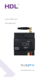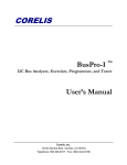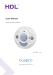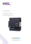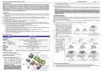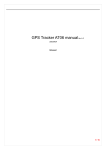
1
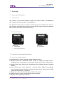
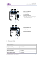
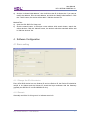
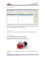
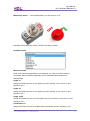
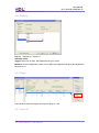
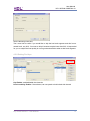
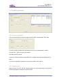
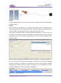
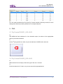
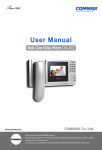
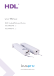
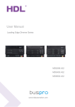
User Manual Dry Contact Sensors HDL-MSD08.40/HDL-MSD04.40 www.hdlautomation.com User Manual HDL- MSD08.40/MSD04.40 INDEX 1. 2. 3. 4. 5. 6. Overview .................................................................................................................... 1 1.1 General Information ............................................................................................. 1 1.1.1 Description ................................................................................................. 1 1.1.2 Serial Numbers .......................................................................................... 1 1.2 Function Qualities Description ............................................................................. 1 1.2.1 Common functionalities.............................................................................. 1 1.2.2 Device Description ..................................................................................... 2 Technical Data ........................................................................................................... 2 Installation .................................................................................................................. 3 3.1 HDL BUS Pro Description .................................................................................... 3 3.2 Commissioning .................................................................................................... 3 Software Configuration .............................................................................................. 4 4.1 Basic setting......................................................................................................... 4 4.1.1 Change the ID of the device ...................................................................... 4 4.1.2 Remark ...................................................................................................... 4 4.2 Configuration........................................................................................................ 5 4.2.1 Remark ...................................................................................................... 5 4.2.2 Switch type ................................................................................................ 5 4.2.3 Unqualifiedde ............................................................................................. 8 4.2.4 Delay time .................................................................................................. 8 4.2.5 Dimming..................................................................................................... 9 4.2.6 Target ......................................................................................................... 9 4.2.7 Low Limit.................................................................................................... 9 4.2.8 Setting For Keys ...................................................................................... 10 4.3 Channel parameter ............................................................................................ 11 4.3.1 For Security Module ................................................................................. 11 4.3.2 Tamper proof ............................................................................................ 11 FAQ.......................................................................................................................... 13 NOTES .................................................................................................................... 14 Dry contact sensors – User Manual User Manual HDL- MSD08.40/MSD04.40 1. Overview 1.1 General Information 1.1.1 Description HDL‘s version 4 Dry Contact modules, 8 channel dry contact module - HDL-MSD08.40 and 4 channel dry contact module - HDL-MSD04.40 The dimension of this product is 45*45*16, quite small and so is suitable to be used in a retrofit project where end-user would like to equip HDL-BUS smart system but would also like to reserve their existing Switch (normal one). 1.1.2 Serial Numbers MSD04.40 4 Channels 4 LED output function MSD08.40 8 Channels 1.2 Function Qualities Description 1.2.1 Common functionalities 4/8 channels Dry Contact Input with tamper detection function. Support Switch type:Mechanical Switch ,Single On ,Single Off, Single On/Off , Combination On, Combination Off, Combination On/Off, Multi-function, Parallel switch. Support switch mode: Switch mode, Dimmable two-way, dimmable increase, dimmable reduced. Control Target type:Scene, Sequence, Universal Switch, Single channel lighting control, Broadcast Scene, Broadcast channel, Curtain Control, Panel Control, GPRS control, Security Module, TT player etc. Tamper-proof, need 1K Ohm resister in parallel to dry contact . Security function, need to be used with the security module. Support online upgrading by HDL Bus. Dry contact sensors – User Manual 1 User Manual HDL- MSD08.40/MSD04.40 1.2.2 Device Description a ○ e ○ a. four channels input b. HDL-Buspro c. LED indicator b ○ d. programming button e. four LED output, corresponding to the four channels input c ○ d ○ a ○ a. eight channels input b. HDL-Buspro c. LED indicator d. programming button b ○ c ○ d ○ 2. Technical Data Electric Parameters: BUS power supply DC12-30V BUS power consumption 10mA/DC24V Environmental Conditions: Working temperature 0℃~45℃ Working relative humidity Up to 90% Dry contact sensors – User Manual 2 User Manual HDL- MSD08.40/MSD04.40 Storage temperature -20℃~+60℃ Storage relative humidity Up to 93% Approved CE RoHS Production Information: Dimensions 45×45×16(mm) Weight MSD04.40:57(g); MAS08.40:45(g) Housing material ABS Installation Screw fix installation IP Protection IP20 3. Installation Screw fix installation 3.1 HDL BUS Pro Description Connector Information buspro DC24V Red COM Black DATA- White DATA+ Yellow 3.2 Commissioning Method One: a) open the HDL-BUS Pro Setup tool. b) Keep pressing the programming button for 3 seconds, it turns to red color. c) on the software, click the “Address management”, and select the “Modify address (when device button is pressed)”, it will show a window like this: Dry contact sensors – User Manual 3 User Manual HDL- MSD08.40/MSD04.40 d) click the “Indicate initial address”, then it will show the ID of this device. If you want to modify the address, fill in the new address, and click the “Modify initial address”. Click the “+Add” button, the device will be add in “ON-line devices” list. Method Two: a) open the HDL-BUS Pro Setup tool. b) click the search button, it will show a new window, click search button, search the online devices. Click the “Add all” button, the devices which be searched will be add in “ON-line devices” list. 4. Software Configuration 4.1 Basic setting 4.1.1 Change the ID of the device Every HDL-BUS device has one Subnet ID and one Device ID, the Device ID should be unique in its Subnet and the Subnet ID should be kept consistent with the Gateway (typically the SB-DN-1IP or HDL-MBUS01IP.431). 4.1.2 Remark Generally set it like “for living room” to indicate some info. Dry contact sensors – User Manual 4 User Manual HDL- MSD08.40/MSD04.40 4.2 Configuration The setting interface is shown above, setting it is same as setting a HDL-BUS panel select mode for each key, and set targets/objects to each key. Some modes are unique and you cannot find them in HDL-BUS panel, though. 4.2.1 Remark Remarks of dry contacts, you may make remarks according to the installation places. 4.2.2 Switch type Two different Switch types - Momentary and Toggle You can find two different types of switch from the market. Toggle Switch - When pressed, it is on, when released, it is off. If “Mechanic switch” is selected for this kind of switch, a momentary effect can be produced. Dry contact sensors – User Manual 5 User Manual HDL- MSD08.40/MSD04.40 Momentary Switch – It is bi-stable switch, you can set it on or off. Generally select “Mechanic switch” mode for this kind of switch. Available modes Mechanic Switch Send out a command (generally the on command, e.g., light on.) when Switch is connected, send out another (generally the off command) when the Switch is disconnected. Single on Assign the Switch can turn on one object only (one channel, or one scene, or one sequence, etc.) Single off Assign the Switch can turn off one object only (one channel, or one scene, or one sequence, etc.) Single on/off Assign the Switch can turn on/off one object only (one channel, or one scene, or one sequence, etc.) Combination on Assign the Switch can turn on multiple objects (channels, scenes, sequence, etc.) Dry contact sensors – User Manual 6 User Manual HDL- MSD08.40/MSD04.40 Combination off Assign the Switch can turn off multiple objects (channels, scenes, sequence, etc.) Combination on/off Assign the Switch can turn on/off multiple objects (channels, scenes, sequence, etc.) Multi-function Long press – combination off (or dim, if dimming is enabled in the Dry Contact module. Dim the first object only, though.) Short press – single on/off Double click – Combination on This mode can be used in, maybe, meeting, by double-click all the lighting can be on, by long-press, all lighting can be off, this can avoid mishandling and so it is more secure. Parallel Switch This key mode is originally designed for retrofit project where the end-users want to implement smart system – HDL-BUS, but they want to reserve the existing toggle buttons, the toggle buttons are to control one public area lighting (e.g., stair lighting) from multiple places Toggle Button1 Lamp Toggle Button2 Lamp Wiring Connect the two toggle buttons to two different dry contact channels Setting Select “Parallel switch” for both dry contact channels Dry contact sensors – User Manual 7 User Manual HDL- MSD08.40/MSD04.40 4.2.3 Unqualifiedde Each channel can set the mode Switch mode: on/off control Dimmable increase: long press to dim up Dimmable reduced: long press to dim down Dimmable two-way: long press to dim up, long press again can dim down 4.2.4 Delay time Just the “Mechanic switch” switch type has the delay time. Dry contact sensors – User Manual 8 User Manual HDL- MSD08.40/MSD04.40 4.2.5 Dimming Key no. : channel no./ switch no. Dimming value: Toggle- when turn on light, the brightness will go to 100% Memory- save the brightness, when turn on light, the brightness will go to last brightness before turn off 4.2.6 Target Can set each channel‟s targets, the target‟s range is 1~99. 4.2.7 Low Limit Dry contact sensors – User Manual 9 User Manual HDL- MSD08.40/MSD04.40 Set the dimming lower limit. The Lower limit is useful if you would like to skip the low level segment and dim from a certain level, say 50%. You want to skip it because maybe lower than 50% is impractical for you or maybe the load quality is not so good and trembles when at low level segment. 4.2.8 Setting For Keys Key Enable: enable/disable the channels Panel Lock Key Enable: If be selected, can use panel to lock/unlock this channel Dry contact sensors – User Manual 10 User Manual HDL- MSD08.40/MSD04.40 4.3 Channel parameter 4.3.1 For Security Module Can use channels of dry contact to trigger security, like the window state, door state. If use dry contact 1 to detect the door state for security, the setting steps as follow: a) Select „key 1‟ here and type in the remark. b) Enable security function. c) Input the security module‟s Subnet/Device ID, totally 8 areas can be selected, here is area 1. For further configuration, please turn to security module‟s user manual. 4.3.2 Tamper proof When the wire is cut off, the Dry Contact module can report the status to the Security module and trigger the alarm by Security module. Dry contact sensors – User Manual 11 User Manual HDL- MSD08.40/MSD04.40 Wiring As above diagram shows, connect a 1K Ohm resistor in parallel to the Sensor (generally a magnetic contact). Setting When the Sensor is connected (e.g., close/open the window), click the “ON Read” button and you will get a value for “Connected (0-100)”, when the Sensor is disconnected, click the “OFF Read” and you will get a value for “Disconnected (0-100)”, save. If every time you read the value, the values changes dramatically, e.g., from 5, to 10, to 30, to 15 again, this means the contact is not reliable, you probably need to check the screws (both the ones on the Dry Contact module and the ones on the sensor), maybe they are not tight enough. When the status of Sensor (the Magnetic Contact) in channel 1 is changed, no matter it is on or off, it will report to the Security module (the 1/12) and it is up to the Security module to trigger the alarm or not (based on the Sensor type set in Security module - Normally Closed type or Normally Open type). When the wire is cut off, we regard this is a more emergency situation, you can set the “Alarm Commands”, Normally you can set it like this, Dry contact sensors – User Manual 12 User Manual HDL- MSD08.40/MSD04.40 PS: You need to authorize the ID (of the Dry Contact module) in Security module, for more setting about Security module, please turn to corresponding doc. 5. FAQ 5.1 DryContactFAQ001_HDL-BUS Q: HDL-MSD04.40 has indicators for four channels output, but where is the appropriate place to put those indicators? A: Some 3rd party panel has a hold, can put the indicator of MSD04.40 in the hold. 5.2 DryContactFAQ002_HDL-BUS Q: MS04.40 has four led output, what‟s the type of led can I connect? A: Each led channel is 5V 10mA, so you can connect the appropriate led. Dry contact sensors – User Manual 13 User Manual HDL- MSD08.40/MSD04.40 6. NOTES Dry contact sensors – User Manual 14