1
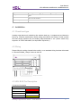
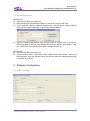
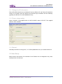
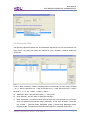
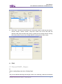
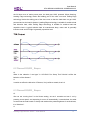
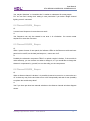
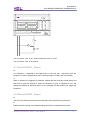
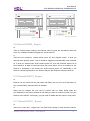
User Manual Leading Edge Dimmer Series MD0206.432 MD0403.432 MD0602.432 www.hdlautomation.com User Manual HDL-MD0206.432/MD0403.432/MD0602.432 INDEX 1. 2. 3. 4. 5. 6. 7. Overview .................................................................................................................... 1 1.1 General Information ............................................................................................. 1 1.1.1 Description ................................................................................................. 1 1.1.2 Mounting .................................................................................................... 1 1.1.3 Serial Numbers .......................................................................................... 1 1.2 Function Qualities Description ............................................................................. 2 1.2.1 Common functionalities.............................................................................. 2 1.2.2 Individual functionalities ............................................................................. 2 1.2.3 Change fuse .............................................................................................. 2 1.3 Device Description ............................................................................................... 3 1.4 Recommend Load Types ..................................................................................... 3 Safety Instructions ..................................................................................................... 3 Technical Data ........................................................................................................... 4 Installation .................................................................................................................. 5 4.1 Check load type, ............................................................................................. 5 4.2 Wiring .............................................................................................................. 5 4.3 HDL BUS Pro Description .................................................................................... 5 4.4 Commissioning .................................................................................................... 6 Software Configuration .............................................................................................. 6 5.1 Basic setting......................................................................................................... 6 5.1.1 Change the ID of the device ...................................................................... 7 5.1.2 Power voltage setting................................................................................. 7 5.1.3 Remark ...................................................................................................... 7 5.2 Area Setup ........................................................................................................... 7 5.3 Channel parameter .............................................................................................. 9 5.3.1 Default setting ............................................................................................ 9 5.3.2 “Load type” ................................................................................................. 9 5.3.3 Dimming Profile ....................................................................................... 10 5.3.4 Load test .................................................................................................. 10 5.3.5 View temperature ..................................................................................... 11 5.4 Scene Setup ...................................................................................................... 11 5.5 Sequence Sept .................................................................................................. 12 FAQ.......................................................................................................................... 13 NOTES .................................................................................................................... 19 Leading Edge Dimmer Series – User Manual User Manual HDL-MD0206.432/MD0403.432/MD0602.432 1. Overview 1.1 General Information 1.1.1 Description Leading edge dimmer is suitable to dim resistive load (e.g., incandescent) and inductive load (e.g., inductive transformer). Before wiring the loads to the Dimmer, check (consult the load vendor) whether they are leading edge dimmable or not. (Some vendor may express it as TRIAC-dimmable, an equivalent expression). 1.1.2 Mounting Standard 35mm Din Rail Installation Inside Distribution Box(DB) 1.1.3 Serial Numbers MD0206.432 MD0403.432 MD0602.432 2 Channels 4 Channels 6 Channels Max. 6A per channel Max. 3A per channel Max. 2A per channel Max.12A total Max.12A total Max.12A total Leading Edge Dimmer Series – User Manual 1 User Manual HDL-MD0206.432/MD0403.432/MD0602.432 1.2 Function Qualities Description Universal dimmers have a number of programmable features. There are listed below: 1.2.1 Common functionalities Short circuit and over heat protection Load test function – for identifying and confirming circuits Bypass button for manual control available for each channel Scenes – for saving present dim levels per Area, that can be recalled by any switch Sequences - Availability to create up to 6 sequences and each sequence can has 12 steps Max level – The maximum percentage a light can go (for energy saving, and light life-extension) Minimum and maximum dimming level – the min and max level a channel dims to before it jumps to 0%, or the Max level Dimming curve exponents – 1.0, 1.5, 2.0 and 3.0. These compensate for the curve of LEDs. The dimming accuracy is 12 steps 1.2.2 Individual functionalities Areas Fuse – for grouping channels so they can be changed with a single command. MD0206.432 MD0403.432 MD0602.432 Up to 2 separated areas Up to 4 separated areas Up to 6 separated areas – fuse aR type protection replaceable in case of damage. MD0206.432 12A fuse of each channel for protection. MD0403.432 MD0602.432 8A fuse of each channel 4A fuse of each channel for protection. for protection. 1.2.3 Change fuse The Dimmer has several fuse on the front cover, one for each channel, easy to replace. They are all aR type fuse, suitable to protect the electronic component TRIAC, and the rated current of the fuse is two times of the electronic component TRIAC, and the rated current of the rated current of the fuse is two times of the rated current of dimmer channel Leading Edge Dimmer Series – User Manual 2 User Manual HDL-MD0206.432/MD0403.432/MD0602.432 1.3 Device Description b ○ a. Fuses and LED indicators b. Heat sink c. Manual buttons d. Programming button e. Line c ○ a ○ f. Neutral g. Protecting Earth d ○ h. Neutral 1 i. Neutral 2 j. Neutral 3 k. Neutral 4 e ○ f ○ g ○ h ○ i ○ j ○ k ○ l ○ m ○ n ○ o ○ p ○ l. Channel 1 m. Channel 2 n. Channel 3 o. Channel 4 p. HDL-Buspro 1.4 Recommend Load Types Loading edge dimmers is suitable to dim resistive load (e.g., incandescent) and inductive load (e.g., inductive transformer). Before wiring the loads to the Dimmer, check (consult the load vendor) whether they are leading edge dimmable or not. (Some vendor may express it as TRIAC-dimmable, and equivalent expression.) The Dimmer has several fuses on the front cover, one for each channel, easy to replace. They are all aR type fuses, suitable to protect the electronic component TRIAC, and the rated current of the fuse is two times of the rated current of dimmer channel 2. Safety Instructions Danger Serious injuries, fire or property damage possible. Please read and follow safety instructions fully. Risk of fatal injury from electrical current All work on the device should only be carried out by trained, fitted and skilled Leading Edge Dimmer Series – User Manual 3 User Manual HDL-MD0206.432/MD0403.432/MD0602.432 electricians. Before working on the device or before exchanging light bulbs, disconnect mains voltage and switch off circuit breakers. Device can be damaged Do not bypass or short-circuit the dimmer. Do not connect any LED, lights with integrated dimmers or compact fluorescent lamps that are not specifically suitable for dimming. Product Manipulation Only operate the device according to the specifications stated in the Technical data. Opening the housing of the device causes the immediate end of the warranty period. 3. Technical Data MD0206.432 MD0403.432 MD0602.432 Electric Parameter : Working power DC15~30V Power consumption 28mA/DC24V Output channel 2CH/6A 4CH/3A Fuse 10A 8A TRIAC 8A 25A TRIAC, Minimum Load 40w Dimming curves Linear, 1.5 exponent, 2.0 exponent, 3.0 exponent 6CH/2A 4A Environmental Condition: Working temperature 0%~45% Working relative humidity Up to 90% Storage temperature -20%~+60% Storage relative humidity Up to 93% Approved CE RoHS Production information: Dimensions 144×90×66 (mm) 216×90×66 (mm) 216×90×66 (mm) Leading Edge Dimmer Series – User Manual 4 User Manual HDL-MD0206.432/MD0403.432/MD0602.432 716(g) Weight 709.6(g) Housing material Nylon Installation 35mm Din Rail installation Protection degree IP20 812.6(g) 4. Installation 4.1 Check load type Loading edge dimmers is suitable to dim resistive load (e.g., incandescent) and inductive load (e.g., inductive transformer). Before wiring the loads to the Dimmer, check (consult the load vendor) whether they are leading edge dimmable or not. (Some vendor may express it as TRIAC-dimmable, and equivalent expression.) 4.2 Wiring Please follow the wiring showed below strictly, a non-standard wiring has been discussed in “DimmerFAQ008_ Buspro” below in this doc. Buspro connector 4.3 HDL BUS Pro Description Connector Information buspro DC24V Red COM Black DATA- White DATA+ Yellow Leading Edge Dimmer Series – User Manual 5 User Manual HDL-MD0206.432/MD0403.432/MD0602.432 4.4 Commissioning Method One: a) open the HDL-BUS Pro Setup tool. b) Keep pressing the programming button for 3 seconds, it turns to red color. c) on the software, click the “Address management”, and select the “Modify address (when device button is pressed)”, it will show a window like this: d) click the “Indicate initial address”, then it will show the ID of this device. If you want to modify the address, fill in the new address, and click the “Modify initial address”. Click the “+Add” button, the device will be add in “ON-line devices” list. Method Two: a) open the HDL-BUS Pro Setup tool. b) click the search button, it will show a new window, click search button, search the online devices. Click the “Add all” button, the devices which be searched will be add in “ON-line devices” list. 5. Software Configuration 5.1 Basic setting Leading Edge Dimmer Series – User Manual 6 User Manual HDL-MD0206.432/MD0403.432/MD0602.432 5.1.1 Change the ID of the device Every HDL-BUS device has one Subnet ID and one Device ID, the Device ID should be unique in its subnet, and the Subnet ID should be kept consistent with the Gateway (typically the SB-DN-1IP or HDL-MBUS01IP.431). 5.1.2 Power voltage setting Select ”AC220V” if the applied mains is 220V~240VAC, select “AC110V” if the applied mains is 100V~120VAC. 5.1.3 Remark Generally set it like “for living room”, or “in DB3”(distribution box 3) to indicate some info. 5.2 Area Setup Below screen shot shows all 4 channels of the Dimmer are not assigned to any area, actually there is no area yet. Leading Edge Dimmer Series – User Manual 7 User Manual HDL-MD0206.432/MD0403.432/MD0602.432 Suppose according to the wiring, channel1 to 2 are used to control 2 lights in living room, channel 3 to 4 are used to control 2 lights in the kitchen. The configuration steps would be like this: a) click “Create area”, area 1 is created, we can find and select it in “Select area”. b) select channel 1 to 2 and move them from left block to the right block, click “save”. c) click “Create area”, area 2 is created, we can find and select it in “Select area”. d) select channel 3 to 4 and move them from left block to right block, click “save”. e) now all channels have been assigned to the areas, no channel is left in the left block. Exit this “Area setup” window, we can name the two areas, i.e., living room and kitchen. Leading Edge Dimmer Series – User Manual 8 User Manual HDL-MD0206.432/MD0403.432/MD0602.432 5.3 Channel parameter 5.3.1 Default setting --Lower limit=0%, Higher limit=100%, Max level=100% “DimmerFAQ011_ Buspro” below in this doc explains the Lower limit, Higher limit and Max level in detail. 5.3.2 “Load type” The “Load type” is a remark, it has nothing to do with the control method or output behavior of Dimmer, doesn’t matter if you leave it unselected. Default selection – Undefined. Leading Edge Dimmer Series – User Manual 9 User Manual HDL-MD0206.432/MD0403.432/MD0602.432 5.3.3 Dimming Profile There are four dimming curves you can select, i.e., “Curve 1.0”, “Curve 1.5”, “Curve 2.0”, “Curve 3.0”. Different loads have different voltage-luminance curve, an ideal voltage-luminance curve is a linear one, means when end-user long press a button it dims p/down gradually and steadily, a dramatically non-linear load may have the undesired effect – at some segment, e.g., 0%~5%, it is insensitive, the luminance changes a little, at some segment, e.g., 50%~100%, it is sensitive, the luminance changes dramatically. To compensate this undesired effect, you can try the four selections of Dimmer, see which one suits the load best. The default selection is “Curve 1.0” and generally no need to change. 5.3.4 Load test Before an end-user panel is configured, this window can be used to trigger the Dimmer/Relay, so as to check the wiring. As below screen shot show, if “Start test” is clicked, the channel 1 of device 1-104 will start to flash (the Interval is set as 2s). After confirmation, click “Stop test” and then “Turn off load”. Leading Edge Dimmer Series – User Manual 10 User Manual HDL-MD0206.432/MD0403.432/MD0602.432 5.3.5 View temperature A large portion of the housing material is metal (Radiator), it is used for heat sink too, a temperature sensor is attached to it and used to monitor the temperature of the heat sink temperature. When it reaches to 78C, Dimmer will start to protect itself by lower the output level, the higher the temperature, the lower the output, if it reaches to 84C, the output will be totally limited to 0%, no output, till the temperature falls down below 78C, the Dimmer will recover the output. 5.4 Scene Setup This Dimmer supports 12 scenes for each area. Scene 0 is reserved by the dimmer, cannot be edited, it is reserved for all off, the “Running time” is editable. “Running time” is explained in “DimmerFAQ003_Buspro” below in this doc. a) Select the “Area”, here we select area 1 – “living room”, suppose area 1 has 4channels. b) Click “Scene setup”, you can edit the “Remark”, “Running time” and “Intensity”. c) Click “Scene restore”, you have two options – “Scene before power off” and “Specified scene”. It is the scene you want the Dimmer to recall when the Dimmer powered on. (see limitation in “DimmerFAQ009_Buspro” below in this doc) Leading Edge Dimmer Series – User Manual 11 User Manual HDL-MD0206.432/MD0403.432/MD0602.432 5.5 Sequence Sept The Dimmer supports 6 sequences, and all these 6 sequences can only be created in one area, here in our case, just area1 has sequences, it is a limitation, suppose area1 has 4channels. If now in area we want to create a sequence which runs this way for ever: step1 (channel 1 on) -> step 2 (channel 2 on) -> step 3 (channel 3 on) -> step 4(channel4 on) -> step 5 (channel 1, 2, 3, 4 off) -> step1 -> step2 -> step 3…. a) Select the “Area”, here we select area 1 – “living room”. b) Click “Remark”, we can name it “flowEffect-nonstop”. c) Click “Sequence”, we need 5 scenes, one for each step, and we want it to run forever once it is started (until end-user stop it manually), so we set it as below. There are four modes – Forward mode, Backward mode, Forward and Backward mode, Random mode. The sequence effect described above is a forward mode effect. Leading Edge Dimmer Series – User Manual 12 User Manual HDL-MD0206.432/MD0403.432/MD0602.432 d) Click “Step”, according to the effects, the 5 scenes we need for each step are scene1, scene2, scene3, scene4, scene0. “Step time” means how much time later the sequence will jump to another step (scene), typically we set it larger than the running time of the scene, here we set 1s larger than the running time of each scene. 6. FAQ 6.1 DimmerFAQ001_ Buspro Q: What is Leading Edge and what is Trailing Edge? A: They are two different dimming technologies. When not in dimming, a dimmer channel lets Leading Edge Dimmer Series – User Manual 13 User Manual HDL-MD0206.432/MD0403.432/MD0602.432 the full sine curve of mains power pass, the load gets 100% powered. When dimming, Leading Edge technology blocks the leading part of the sine curve and Trailing Edge technology blocks the trailing part of the sine curve so that the load does not get 100% powered and so the load is dimmed. Leading Edge technology is suitable for resistive load and inductive load, while Trailing Edge technology is suitable for resistive load and capacitive load. A typical resistive load is incandescent lamp, motor and is generally inductive load and LED light is generally capacitive load. 6.2 DimmerFAQ002_ Buspro Q: What is the selection “Load type” in HDL-BUS Pro Setup Tool? Would it affect the behavior of the dimmer? A: It would not affect the behavior of Dimmer, it is just like a remark, that is it. 6.3 DimmerFAQ003_ Buspro Q: We can set “running time” in the Scene setting, we set 3 seconds and turn it on by pressing a user panel, and expecting it to turn off automatically 3 seconds later, but what we saw was the load turned on slowly and reached the preset brightness 3 seconds later, it is “fade time”. A: Leading Edge Dimmer Series – User Manual 14 User Manual HDL-MD0206.432/MD0403.432/MD0602.432 Yes, maybe “fade time” or “transition time” is easier to understand for some people. PS: You can find “running time” setting in user panel also if you select “Single channel lighting control” command. 6.4 DimmerFAQ004_ Buspro Q: I cannot have Sequence in more than one area? A: Yes, Sequence can only be created in one area. It is a limitation. You cannot create sequence in more than one area. 6.5 DimmerFAQ005_ Buspro Q: When I press a button of user panel, the indicator LEDs on the Dimmer module and user panel can be on/off, but the load just keeps on, I cannot turn it off. A: Probably the electronic component TRIAC or optical coupler is broken, if the module is under warranty, you can contact our sales to change it, or if you would like to change the electronic components by yourself, we can also ship you the components. 6.6 DimmerFAQ006_ Buspro Q: When a dimmer channel is broken, it is possible it cannot be turned on or cannot be turn off. Is there any way for the end user to turn on/off it temporarily and wait for me (Installer) to replace the module days later? A: Yes if you have pre-wired two manual switches to the dimmer channel as below diagram shows. Leading Edge Dimmer Series – User Manual 15 User Manual HDL-MD0206.432/MD0403.432/MD0602.432 Turn on Lamp1: Turn on S1, doesn’t matter the S2 is on or off. Turn off Lamp1: Turn off S1 and S2. 6.7 DimmerFAQ007_ Buspro Q: In a Sequence, I assigned a full bright scene to the last step, I expected when the Sequence is over or stopped by a user, it will stay bright, but what I got was full dark. A: When a Sequence is triggered, the dimmer module will first save the current status and then start to play the Sequence, when the Sequence is over or stopped by user, the dimmer will restore its previous status, so it is probably full dark before your trigger the Sequence. 6.8 DimmerFAQ008_ Buspro Q: The HDL new dimmer produces more noise than I have expected, any solutions? A: Please check the wiring, non-standard wiring can lead to unexpected more noise. Leading Edge Dimmer Series – User Manual 16 User Manual HDL-MD0206.432/MD0403.432/MD0602.432 Buspro connector Buspro connector 6.9 DimmerFAQ009_ Buspro Q: There is “Scene restore” setting in the Dimmer, which is great, but sometimes it does not work, any conditions needed to trigger the “scene restore”? A: There are two selections, “Scene before power off” and “Specific scene”, if what you selected was “Specific scene”, then it should be triggered unconditionally when powered on, if what you selected was “Scene before power off”, then the channels’ status has to have lasted for at least 20 seconds before the power failure, this is a condition for the Dimmer to guarantee it can restore the “Scene before power off”. Additionally, if the Dimmer was playing Sequence, the Dimmer will play the Sequence when powered on. 6.10 DimmerFAQ010_ Buspro Q: Dimmer can turn on/off and dim the loads, and Relay can only turn on/off the loads, so why we need Relay, because Relay is cheaper? A: Relay may be cheaper but you need to confirm with our sales. Some loads are non-dimmable, in this case it is better to use Relay to control it, however it is OK if you use Dimmer to do ON/OFF control only, you just need to disable the dim option in user panel. 6.11 DimmerFAQ011_ Buspro Q: There are “Lower limit”, “Higher limit” and “Max level” setting for each dimmer channel, Leading Edge Dimmer Series – User Manual 17 User Manual HDL-MD0206.432/MD0403.432/MD0602.432 and the default values for them are Lower limit=0%, Higher limit=100%, Max level=100%, what are they and in what case I need to configure them? A: Yes, e.g., if you set Lower limit=30%, Higher limit=80% and Max level=90%, and then you use a user panel to command the dimmer channel to go to 40%, the Dimmer will find the value 40% is in the range 30% ~80%, and so the channel output will be 40%, but if you command the dimmer channel to go to 20%, the Dimmer will find the 20% is lower than the Lower limit (30%) and the channel output will be 0%, if you command 85%, the Dimmer will find 85% is higher than the Higher level(80%), and the channel output will be the Max level(90%). The Lower limit is useful if you unfortunately have some lamps which produce unstable (trembling) light when dimming in low segment. You can bypass the unstable segment by setting a suitable Lower limit. 6.12 DimmerFAQ012_ Buspro Q: When I turned off a dimmer channel, to my surprise, I saw the load, a LED, keep flickering. A: Leading Edge Dimmer have a little leak current when they are turned off, this leak current may lead to low wattage LED to flicker. If the load is 30W or higher, the leak current is not enough to power it and make it flicker. If the load wattage is less than 30W and you find there is flicker, then you can connect one MCR01.40 to the load in parallel to solve the flicker problem. HDL sells LED also, and claims all its LEDs do not have flicker problem. Leading Edge Dimmer Series – User Manual 18 User Manual HDL-MD0206.432/MD0403.432/MD0602.432 7. NOTES Leading Edge Dimmer Series – User Manual 19