1
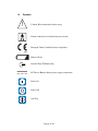
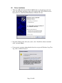
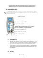
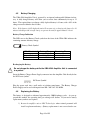
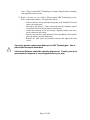
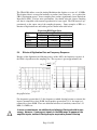
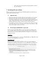
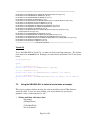
Model UBA-4204 Universal Biomedical Amplifier User’s Manual Version 2.1 January 25, 2011 0086 TABLE OF CONTENTS 1 SAFETY SECTION............................................................................................................................ 4 1.1 1.2 1.3 1.4 1.5 1.6 1.7 1.8 1.9 1.10 WARRANTY INFORMATION .......................................................................................................... 4 CONTACT INFORMATION .............................................................................................................. 5 PRECAUTIONS .............................................................................................................................. 5 SYMBOLS ..................................................................................................................................... 6 APPROVALS .................................................................................................................................. 7 EUROPEAN REPRESENTATIVE ....................................................................................................... 7 PRODUCT INTRODUCTION ............................................................................................................ 7 SPECIFICATIONS ........................................................................................................................... 9 SOFTWARE LICENSE ..................................................................................................................... 9 RECALIBRATION AND MAINTENANCE .......................................................................................... 9 2 PARTS, ACCESSORIES, AND CONFIGURATIONS................................................................. 10 3 SETTING UP THE UBA.................................................................................................................. 11 3.1 3.2 4 USING THE UBA-4204.................................................................................................................... 13 4.1 4.2 4.3 4.4 4.5 4.6 5 GENERAL INFORMATION ............................................................................................................ 21 STARTING AND ENDING.............................................................................................................. 21 SETTING AMPLIFIER PARAMETERS ............................................................................................. 22 FUNCTIONS TO COLLECT A FIXED NUMBER OF SAMPLES ........................................................... 23 CONTINUOUS DATA COLLECTION .............................................................................................. 25 MEMORY ALLOCATION AND MANAGEMENT .............................................................................. 25 DATA COLLECTION .................................................................................................................... 25 IMPEDANCE MEASUREMENT ...................................................................................................... 26 CALIBRATION ............................................................................................................................. 26 INTERFACING WITH YOUR SOFTWARE ............................................................................... 27 7.1 7.2 7.3 7.4 8 GAIN SELECTION ........................................................................................................................ 18 MAXIMUM SAMPLING RATE....................................................................................................... 18 EFFECTS OF DIGITIZATION RATE AND PREAMP GAIN ON INPUT NOISE ...................................... 18 EFFECTS OF DIGITIZATION RATE ON FREQUENCY RESPONSE ..................................................... 19 INPUT IMPEDANCE...................................................................................................................... 20 DIGITAL FILTERS........................................................................................................................ 20 INTRODUCTION TO THE UBA4204 DLL FUNCTIONS.......................................................... 21 6.1 6.2 6.3 6.4 6.5 6.5.1 6.5.2 6.6 6.7 7 POWERING ON/OFF .................................................................................................................... 13 SELF TEST .................................................................................................................................. 13 UBA 4200C INTERFACE UNIT ..................................................................................................... 14 INPUT CONNECTIONS ................................................................................................................. 14 BATTERY CHARGING.................................................................................................................. 16 REPLACING THE BATTERY ......................................................................................................... 16 CONSIDERATIONS FOR USE ...................................................................................................... 18 5.1 5.2 5.3 5.4 5.5 5.6 6 PRODUCT INTERCONNECTION .................................................................................................... 11 DRIVER INSTALLATION .............................................................................................................. 12 IMPORTANT NOTES ..................................................................................................................... 27 REFERENCING THE UBA4204 DLL IN YOUR CODE .................................................................... 27 USING THE UBA4204 DLL TO COLLECT A FIXED NUMBER OF SAMPLES .................................... 28 USING THE UBA4204 DLL FOR CONTINUOUS DATA COLLECTION ............................................. 29 UTILIZING THE UBA4204 DLL WITH MATLAB AND LABVIEW....................................... 30 Page 2 of 30 8.1 8.2 MATLAB ................................................................................................................................... 30 LABVIEW.................................................................................................................................. 30 Page 3 of 30 1 Safety Section 1.1 Warranty Information LKC Technologies, Inc. unconditionally warrants this instrument to be free from defects in materials and workmanship, provided there is no evidence of abuse or attempted repairs without authorization from LKC Technologies, Inc. This Warranty is binding for one year from date of initial delivery and is limited to: servicing and/or replacing any instrument, or part thereof, returned to the factory for that purpose with transportation charges prepaid and which are found to be defective. This Warranty is made expressly in lieu of all other liabilities and obligations on the part of LKC Technologies, Inc. DAMAGE UPON ARRIVAL. Each instrument leaves our plant, after rigorous tests, in perfect operating condition. The instrument may receive rough handling and damage in transit. The shipment is insured against such damage. The Buyer must report, in writing, immediately any concealed or apparent damage to the last carrier. Report any damage also to us, and issue an order for replacement or repair. DEFECTS OCCURRING WITHIN WARRANTY PERIOD. Parts of units may develop defects that no amount of initial testing will reveal. The price of our instruments makes provision for such service, but it does not: 1. 2. 3. Provide for transportation charges to our factory for service, Provide for services not performed or authorized by us, Provide for the cost of repairing instruments that have obviously been abused or subjected to unusual environments for which they have not been designed. We will be happy at any time to discuss by phone, letter, FAX, or e-mail suspected defects or aspects of instrument operation that may be unclear. We advise you to inform us by phone, letter, FAX, or e-mail of the nature of the defect before returning an instrument for repair. Many times a simple suggestion will solve the problem without returning an instrument to the factory. If we are unable to suggest something that solves the problem, we will advise you as to what parts of the equipment should be returned to the factory for service. DEFECTS OCCURRING AFTER WARRANTY PERIOD. Charges for repairs after the warranty period will be based upon actual hours spent on the repair at the then prevailing rate, plus cost of parts required and transportation charges; or you may elect to purchase an extended warranty. We will be happy to discuss by phone, letter, FAX, or e-mail any problem you may be experiencing. Page 4 of 30 1.2 Contact Information LKC Technologies, Inc. Customer Service/Support 800.638.7055 (US & Canada) 1.301.840.1992 (Worldwide) 1.301.330.2237 (FAX) [email protected] www.LKC.com 1.3 ! Precautions ♦ Ensure the amplifier battery is fully charged prior to use. ♦ Do not record from human subjects while the Amplifier Unit battery is recharging. ♦ Use only the provided battery or an exact replacement from LKC Technologies. ♦ Use only the provided battery charger power supply or an exact replacement from LKC Technologies. ♦ This device is not protected against the ingress of water and should not be used in the presence of liquids that may enter the device. ♦ This device is not suitable for use in the presence of flammable anesthetics or other flammable vapors or liquids. Page 5 of 30 1.4 Symbols ! Caution! Read instructions before using. Patient connection is isolated from power mains European Union Council Directive compliance 0086 Battery Check Data I/O Port (TOSlink cable) DC Power (Battery charger power supply connection) Power On Power Off Self-Test Page 6 of 30 1.5 Approvals This product has been tested for EMI and complies with the requirements of EN 60601-11-2:2001 (Group 1 Class A device under CISPR 11). Use of this equipment in the vicinity of other equipment with excessive EMI may interfere with the proper operation of this product. This product conforms to IEC601-1:1988 with Amendments A1:1991 and A2:1995, and to EN60601-1:1990. This product has been tested in accordance with AAMI Safe Current Limits Standard and meets all requirements for direct patient connection. The product is an USB powered device designed to meet the applicable requirements of UL 60601-1 Standard for Safety (Medical and Dental Equipment). This device should only be used according to the manufacturer’s instructions and by qualified health professionals. This product has been approved for both CE and CB certificates 1.6 European Representative Emergo Europe Symbol Molenstraat 15 2513 BH The Hague The Netherlands Tel: (31) (0) 70-345-8570 Fax: (31) (0) 70-346-7299 1.7 Product Introduction The LKC UBA-4204 is a Biomedical Amplifier. It is designed to measure low-level bioelectrical signals and transmit their digital representation to a computer through a Universal Serial Bus (USB) port to a computer running the Windows XP operating system. ! The UBA-4204 was designed and tested for use with the Windows XP operating system. While it may work properly with Windows Vista, it has not been tested in this environment. Drivers are not presently available for the Mac OS or Linux. Page 7 of 30 The UBA-4204 consists of an Amplifier Unit and an Interface Unit connected by a fiber optic (TOSlink) cable. The amplifier unit has four differential inputs and is powered by a rechargeable Lithium-Ion battery. The Interface Unit connects to a USB 1.1 port to receive power and to send digital data to a computer or PDA. Inputs to the system run through a preamplifier / buffer with programmable gains of 1, 2, 4, 8, 16, 32, or 64. After buffering, the data are immediately digitized by a 24-bit sigma-delta Analog to Digital Converter. The data are then sent in digital form over the fiber optic TOSlink connector to the Interface Unit, and from there to the USB port of the computer. No analog data is transmitted! Commands are transmitted from the computer via the USB bus to the Interface Unit, which sends them up the second fiber of the TOSlink cable to the Amplifier, where they are interpreted and executed by the on-board microcomputer. An internal rechargeable Lithium Ion battery provides power for the Amplifier Unit. Power for the Interface Unit is provided by the USB connection. A block diagram of the system is shown below: Computer High Resolution Analog to Digital Converter Electrode + Short Cable Interface Unit Pure Digitized Signal Over Fiber Optic The UBA-4204 as furnished is designed to be incorporated into your custom biomedical data acquisition and analysis system. It is furnished with the software components necessary to allow you to control it and collect data from your Windows XP program in: ♦ Visual C++ ♦ Visual C# ♦ Visual Basic ♦ MatLab ♦ LabVIEW ♦ Any other system that allows you to access a DLL driver. Page 8 of 30 1.8 Specifications AMPLIFIER UNIT INTERFACE UNIT Input Type Input Channels Input Impedance Connector Type Analog Differential or Single Ended 4 (user selectable) ≥10 MΩ 1.5 mm Male DIN Safety electrode connections or optional BNC connectors Background Noise < 0.7 µV p-p @ 100 Hz Sampling Rate, 10 KΩ Input < 1.8 µV p-p @ 1000 Hz Sampling Rate, 10 KΩ Input CMRR Frequency Range > 100 dB at 50 – 60 Hz Input Gain DC Input Range Stability Accuracy Calibration Data Resolution Sampling Rate Data Connection Safety 1, 2, 4, 8, 16, 32, 64 (user selectable) ±2 V (Gain = 1) < 250 nV / °C drift < 0.2% absolute, Nonlinearity < 0.0010% Automatic gain and offset calibration on demand 0.25 µV / bit (Gain = 1) to 3.7 nV / bit (Gain = 64) 2.5 Hz to 15 kHz Bidirectional fiber optic cable (TOSlink) to Interface Unit < 1 nA Leakage Current; > 4 kV Isolation when operated according to instructions Rechargeable Li-Ion Battery 100-240 V 50/60 Hz, 12 V 1.0 A (included) Up to 12 hours of continuous use before recharging 4 hours to 80% capacity, 8 hours to 100% 0° C to 55° C (32° F to 131° F) 5¾” x 3¼” x 1” (14.6 cm x 8.3 cm x 2.5 cm) 8 oz. (225 g), including battery Power Source Battery Charger Operating Time Recharge Time Environmental Size Weight 1.9 Computer Interface USB 1.1 Power Source USB powered Size 6” x 3” x 2¼“ (15 cm x 7.6 cm x 5.7 cm) Weight 8 oz. (225 g) AC Coupled with a frequency range of 0.1 Hz to 15 kHz Software License The UBA driver software is a copyrighted product of LKC Technologies, Inc. and is included with UBA-4204 system under the following license agreement: The software may be used in conjunction with the UBA-4204 system only. The purchaser of the UBA-4204 may make copies of the software for convenience of use, provided the LKC copyright notice is preserved with each copy. This license specifically prohibits the use of this software in a system that does not include an UBA-4202 Interface Unit. 1.10 Recalibration and Maintenance The digitizer of the UBA-4200 series biomedical amplifier is designed with a stable internal voltage reference that should not drift significantly with time. We recommend that the calibration of the unit be verified every 3 years. The UBA-4200 series biomedical amplifier does not require routine maintenance. Should the internal rechargeable battery need to be replaced, see the instructions in Section 4.6. The UBA-4200 series amplifier headend can be cleaned, if needed, with a cloth dampened with a mild detergent solution. Do not immerse the amplifier in any cleaning solution, as it is not watertight. Page 9 of 30 2 Parts, Accessories, and Configurations The UBA-4204 is shipped with the following components: 1 1 1 1 1 1 1 1 1 Model UBA-4204 Amplifier Unit Model UBA-4200 Interface Unit USB A-to-B Cable (~2 m) Dual Channel TOSlink Fiber Optic Cable Battery charger power supply with power cord User’s Manual CD-Rom with Software Storage Box Lanyard Page 10 of 30 3 Setting Up the UBA 3.1 Product Interconnection Inputs Amplifier Unit Interface Unit TOSlink Cable USB Cable (to computer) UBA-4204 Interconnection Diagram UBA-4200 Interface Front View UBA-4200 Interface Back View ♦ Connect one end of the TOSlink fiber optic cable to the data port on the UBA-4204 Amplifier. The data port is identified with a nector will only insert in one orientation. symbol. The con- ♦ Connect the other end of the TOSlink fiber optic cable to the data port on the Model 4200 Interface ♦ Connect the USB cable to the Model 4200 Interface. ♦ Connect the other end of the USB cable to any USB port on your computer. ♦ If desired, clip the lanyard to the loop near the electrode connections on the UBA4204 amplifier. The lanyard may be placed around a person’s neck to support the UBA-4204 during recording sessions. ♦ That’s it! You’re done. Page 11 of 30 3.2 Driver Installation • When the USB cable from the Model 4200 Interface is plugged into your computer, the Windows operating system will recognize that a new USB device has been connected. The Found New Hardware Wizard will start. • Insert the CD that came with your system, select “Install the software automatically” and click Next >. • If you receive a prompt stating that the driver has not passed Windows Logo Testing, click “Continue Anyway” Page 12 of 30 The drivers for your UBA-4204 will automatically install. At the end of the installation, you should receive a prompt stating the hardware installed properly. • 4 Using the UBA-4204 ! The UBA-4204 amplifier unit is powered by an internal Lithium Ion battery. Before using the product for the first time, charge the battery for at least 8 hours following the directions in Section 4.5. Amplifier Controls TECHNOLOGIES UBA-4200 Series Universal DC Biomedical Amplifier OFF TEST ON Press to turn the amplifier OFF Press to test the amplifier The green light will come on when the “Test” button is pressed if the amplifier is functioning properly Press to turn the amplifier ON Power / battery status indicator Battery Charging indicator TOSlink Connector Battery Charger Connector 4.1 Powering On/Off ♦ Press the “On” button for at least ½ second to turn the Amplifier on. The Power Light / Battery Status Indicator will illuminate. Within approximately one second, it may change color to indicate the remaining battery capacity. ♦ If the amplifier is not in use for more than 30 minutes, it will automatically turn off. If you wish to power off before this to conserve battery power, press the “Off” button. 4.2 Self Test Page 13 of 30 To verify that the system is working properly, press the Test button. If the associated green light turns on, the Amplifier Unit microprocessor is working properly. If the green light does not illuminate, press the OFF button, then turn the unit back on by pressing the ON button. This will reset the system. In some UBA models, an error diagnostic has been added to the self-test indicator. If the associated green light turns on and remains on without pressing the Test button, there may be an issue with your amplifier. Please contact LKC Technologies Customer Support if you have any concerns. Note: The Self-Test button does not work if the unit is turned off. The Power / Battery Status indicator must be illuminated for the Self-Test to work. 4.3 UBA 4200c Interface unit When the interface is plugged into the PC, the green light will turn on. If the green light is off, check the connection to the PC. In some UBA models, when the interface is transferring data during data acquisition, the light will flicker. If flickering stops during data collection, make sure the amplifier unit is turned on and connected to the interface unit. Please contact LKC Technologies Customer Support if you have any concerns. 4.4 Input Connections The inputs to the UBA-4204 are 1.5 mm male DIN safety connectors, which accommodate connections to most electrodes. There are 4 differential inputs and a ground / common connection. 4 3 2 1 C + Model UBA-4204 (PATENT PENDING) Serial Number LKC Technologies, Inc. 2 Professional Drive, Suite 222 Gaithersburg, MD 20879 USA Phone: 301.840.1992 Fax: 301.330.2237 [email protected] www.LKC.com UBA-4204 Back Label Page 14 of 30 Differential Input Configuration. The differential inputs are labeled 1+, 1–, 2+, 2–, 3+, 3–, 4+, 4–, where + and – refer to the non-inverting and inverting inputs respectively. Page 15 of 30 4.5 Battery Charging The UBA-4204 Amplifier Unit is powered by an internal rechargeable Lithium-ion battery. A fully charged battery will allow you to collect data continuously for up to 12 hours. The required time to recharge a fully depleted battery is 8 hours, with ~80% of the charge restored within the first 4 hours. Note: If the battery is fully depleted (unit will not turn on), recharging the battery for 10 minutes should provide enough charge to operate the unit for approximately ½ hour. Battery Charge Indication The LED next to the Battery Check symbol on the front of the UBA-4204 indicates the remaining amount of battery charge. Battery Check Symbol LEDs Illuminated Green Green + Red Red Battery Charge > 30 % 10 % - 30 % < 10 % Remaining Hours >3 1-3 <1 Recharging the Battery ! Do not charge the battery while the UBA-4204 Amplifier Unit is connected to a patient. Insert the Battery Charger Power Supply connector into the Amplifier Unit directly below the DC Power symbol. DC Power Symbol Plug the power cord into a wall outlet or isolation transformer. The Battery Charger Power Supply can be used with inputs from 100 - 240 VAC 50 / 60 Hz. 4.6 Replacing the Battery The battery is designed to withstand approximately 5,000 discharge cycles. As you approach this number, the operating time per recharge will decline. If you need a battery replacement you have two options. 1) Return the amplifier unit to LKC Technologies where trained personnel will install a replacement battery. (Battery replacement is not covered under war- Page 16 of 30 ranty.) Please contact LKC Technologies Customer Support before returning your amplifier for this service. 2) Replace the battery at your facility. Please contact LKC Technologies to purchase a replacement battery. To replace the battery: • Remove the four screws from the back panel of the Amplifier Unit and remove the back panel. • Disconnect the battery’s 2-wire connector from the amplifier printed circuit board and remove the battery from the unit. • Attach the connector to the new battery, aligning similar color wires on the connector and battery. • Remove the protective strip from the Velcro attachment, and carefully place the battery onto the back panel. • Replace the back panel and carefully reinsert and tighten the four screws. Use only a genuine replacement battery from LKC Technologies. Use of other batteries may be hazardous. ! Lithium Ion Batteries should be carefully disposed of. Contact your local government for disposal or recycling practices in your area. Page 17 of 30 5 Considerations for Use 5.1 Gain Selection The Full Scale Range and Resolution of the system are shown for each preamplifier gain in the table below. Buffer Gain 1 2 4 8 16 32 64 • Full Scale Range ± 2.000 V ± 1.000 V ± 500 mV ± 250 mV ± 125 mV ± 62.5 mV ±31.25 mV Resolution 0.24 µV / bit 119 nV / bit 60 nV / bit 30 nV / bit 15 nV / bit 7.5 nV / bit 3.7 nV / bit Considerations for gain settings using the AC-coupled UBA The AC-coupled version of the UBA-4204 will not respond to DC offsets at the input. Thus, the buffer gain should be set as high as possible to maximize the resolution of the system. 5.2 Maximum Sampling Rate The UBA-4204’s maximum sampling rate depends on the number of channels used. Channels 1 2-3 4 5.3 Maximum Sampling Rate 15,000 Hz 7,500 Hz 3,750 Hz Effects of Digitization Rate and Preamp Gain on Input Noise Page 18 of 30 The UBA-4204 utilizes a one-bit Analog Modulator that digitizes at a rate of 1.92 MHz. This digitized data is averaged in hardware to produce lower data rates. As a result of the UBA’s digitization process, slower sampling rates produce significantly lower Equivalent Input Noise (EIN). For best noise performance, you should select the slowest sampling rate that is compatible with accurate reproduction of your signal. The EIN increases approximately as the square root of the sampling frequency. Some examples of EIN as a function of digitization rate and buffer gain are shown in the table below. Digitization Rate 50 Hz 500 Hz 2000 Hz 7500 Hz 5.4 Equivalent RMS Input Noise Preamplifier Gain 1 8 0.63 µV 0.22 µV 1.95 µV 0.65 µV 4.2 µV 1.5 µV 7.3 µV 2.4 µV 64 0.12 µV 0.37 µV 0.65 µV 1.2 µV Effects of Digitization Rate on Frequency Response Because of the digitization and filtering process of the ADCs, the frequency response of the UBA is dependent on the sampling rate. The response is given approximately by: sin ( f / f s ) R( f ) = ( f / fs ) 5 where fs is the sampling rate. The response of the system for fs = 30,000 Hz is shown in the graphs below For frequencies greater than fs / 2 (the frequency at which aliasing becomes a concern) the input is attenuated by at least 20 dB; for frequencies greater than 3 fs / 4, the input is attenuated by at least 60 dB. There are additional windows of sensitivity centered at 1.92 MHz, 3.84 MHz, etc. ! In most circumstances, no additional anti-aliasing filtering should be necessary. However, if you expect signals in the MHz range to appear at the amplifier inputs, external filtering may be required to prevent aliasing. Page 19 of 30 5.5 Input Impedance The input impedance of the UBA-4204 is always greater than 10 MΩ. However, at lower sampling frequencies, the input impedance can be significantly higher. Values are shown in the table below. Sampling Frequency > 1,000 Hz 1000 Hz 60 Hz – 500 Hz ≤ 50 Hz Input Impedance 10 MΩ 20 MΩ 40 MΩ 80 MΩ 5.6 Digital Filters The UBA DLL contains functions to implement digital high pass, low pass, and notch filters. The filters are implemented as Infinite Impulse Response second order Butterworth filters. [For the non-technical, this means that the filters will affect the data in a manner very similar to a hardware filter.] ! Filtering only applies when you are collecting a fixed number of samples. For continuous data collection, you must implement your own filtering routines. Page 20 of 30 6 Introduction to the UBA4204 DLL Functions ! In August 2009, LKC released Version 2 of the UBA DLL. We strongly recommend that users of the earlier (Version 1) DLL upgrade to the new version. This manual discusses only the Version 2 DLL and associated software. 6.1 General Information Errors All functions return an error code. The error codes are given in the table below: Error Code 0 1 2 3 4 5 6 7 8 9 10 11 15 Interpretation No error or Data ready Unable to communicate with amplifier Invalid parameter value specified Unused Not all parameters have been set Amplifier is busy (continuous data collection) Data not ready No data collection in process Memory not allocated (see section 6.5.1) Not in continuous data collection mode Buffer overrun Manufacturing commands not enabled Other error Data All data collected by the UBA are expressed in microvolts (µV) as a floating point number. In Visual C++ this is a float; in Visual Basic this is a single. Functions The function prototypes below are given in C++ syntax. 6.2 Starting and Ending Function Prototype: Arguments: Returns: Actions: Notes: int OpenAmp(void) None Error codes as specified in Section 6.1 Creates an instance of the amplifier within the DLL. This function must be called before any other function in the DLL can be used. Function Prototype: int CloseAmp(void) Arguments: None Page 21 of 30 Returns: Actions: Notes: 6.3 Error codes as specified in Section 6.1 Removes the instance of the amplifier. This function must be called before your program exits to avoid memory leakage. Setting Amplifier Parameters There is a single function to initialize the parameters for data collection. Function Prototype: int SetAmpParams (int Parameters[12]) Arguments: Parameters[12] Array containing the amplifier parameters The array parameters are: Index Meaning 0 Unused 1 Unused 2 Rate 3 Number of Samples 4 Channel Select 5 Preamp Gain 6 High Pass Frequency x10 7 Low Pass Frequency x10 8 Notch Frequency 9 Unused 10 Unused 11 Unused Returns: Parameter Unused Values Error codes as specified in Section 6.1 Notes Set to 0 Rate Valid sample rate values are: 30000, 15000, 7500, 3750, 2000, 1000, 500, 100, 60, 50, 30, 25, 15, 10, 5. Passing other values will result in Error Code 2 Invalid Parameter Specified Number of Samples Valid sample numbers are 64, 128, 256, 512, 1024, 2048, 4096, 8192, 16384, 32768 or 65536. Passing other values will result in Error Code 2 Invalid Parameter Specified. This parameter is ignored for continuous data collection. Page 22 of 30 Parameter Notes Determines which channels will be sampled. Valid values are: Desired Binary Hex Decimal Channels Value Value Value 1 0001 0x0001 1 1, 2 0011 0x0003 3 1, 2, 3 0111 0x0007 7 1, 2, 3, 4 1111 0x000F 15 Channel Select Preamp Gain High Pass Frequency x10 Low Pass Frequency x10 Notch Frequency ! Valid values of preamplifier gain are 1, 2, 4, 8, 16, 32, 64. Passing other values will result in Error Code 2 Invalid Parameter Specified Corner (- 3dB) frequency for the high pass filter in 0.1 Hz units. Setting this variable to -1 disables software high pass filtering. Corner (- 3dB) frequency for the low pass filter in 0.1 Hz units. Setting this variable to -1 disables software low pass filtering. Notch filter frequency in Hz. Setting this variable to -1 disables notch filtering. Valid notch filter values are -1, 50, 60. Passing other values will result in Error Code 2 Invalid Parameter Specified Notes: 1. This function takes 300 - 500 msec to set parameters and recalibrate the amplifier. 2. The DLL will not verify that (sampling rate x channels) exceeds the channel capacity as described in Section 5.2. If the channel capacity is exceeded, bytes of transmitted data will be dropped, resulting in corrupted data. 3. High Pass, Low Pass, and Notch filtering apply only when collecting a fixed number of samples. For continuous data collection, you must implement your own digital filtering routines. 6.4 Functions to Collect a Fixed Number of Samples Before collecting data using these functions, you must call OpenAmp() and SetAmpParams(). Function Prototype: Arguments: Returns: Actions: int CollectDataWait(void) None Error codes as specified in Section 6.1 1) Verifies that all parameters for data collection are properly set. 2) Allocates sufficient memory to hold the data, freeing any previously allocated memory Page 23 of 30 Notes: Function Prototype: Arguments: Returns: Actions: Notes: 3) Initiates collection of data from headend and storage in the allocated buffer. 4) Waits until all data are received before returning Data are left in the allocated buffer on completion, and must be retrieved by the GetChannelData() function for each channel. int CollectDataNoWait(void) None Error codes as specified in Section 6.1 1) Verifies that all parameters for data collection are properly set. 2) Allocates sufficient memory to hold the data, freeing any previously allocated memory 3) Initiates collection of data from headend and storage in the allocated circular buffer. 4) Immediately returns Completion of data collection can be tested with the DoneYet() function. Data are left in the allocated buffer on completion, and must be retrieved by the GetChannelData() function for each channel. Function Prototype: int DoneYet (void) Arguments: None. Returns: Returns 0 if data collection is complete. Otherwise, returns an error code as specified in Section 6.1 Actions: 1) Determines if data collection is occurring 2) Determines if all samples have been collected Remarks: This function is called to check if the current data acquisition is finished. Function Prototype: int GetChannelData (int Chan, float *Data) Arguments: Chan Channel of data to be retrieved. Valid channel numbers are 1 to 4. Data Pointer to a buffer to hold the sample data points for this channel Returns: Error codes as specified in Section 6.1 Actions: 1) Determines if a valid channel number has been passed 2) Determines if data collection is complete 3) Filters the data (if required) 4) Copies the filtered data into Data Notes: The calling program is responsible for allocation of memory for the Data buffer. This function is called to retrieve data after it as been acquired using CollectDataWait() or CollectDataNoWait(). Channel number is invalid if it was not specified for data collection by the SetChannels() command. Page 24 of 30 6.5 Continuous Data Collection 6.5.1 Memory Allocation and Management The calling program is responsible for assuring that memory has been allocated within the DLL interface to account for the samples that will be stored during continuous data collection. The functions listed below provide this management ability. Function Prototype: Arguments: Returns: Actions: Notes: Function Prototype: Arguments: Returns: Actions: Notes: int AllocateBuffer (int NSam) NSam maximum number of samples to be buffered Error codes as specified in Section 6.1 1) Compute amount of memory to allocate 2) If any existing memory is allocated (from a previous call to this function without a call to free it), free the previously allocated memory 2) Attempt to allocate memory 3) Report success or failure This function must be called before continuous data collection. Because the memory is organized as a circular buffer, it need not be large if data will be removed by the GetNextData() function at a rate comparable to the data delivered by the NewHorizon amplifier. int FreeBuffer(void) None Error codes as specified in Section 6.1 1) Determine if a buffer was allocated by AllocateBuffer() 2) Free the allocated memory Allocated memory should be freed when no longer useful to prevent memory leakage. AllocateBuffer() will only allocate a single buffer. 6.5.2 Data Collection Before collecting data using these functions, you must call OpenAmp(), SetAmpParams(), and AllocateBuffer(). Function Prototype: Arguments: Returns: Notes: int StartContinuousData (void) None. Error codes as specified in Section 6.1 This function initiates on-going data acquisition. Data sent by the NewHorizon amplifier are stored in the allocated circular buffer. Data are retrieved from the circular buffer by calling GetNextData(). During continuous data acquisition, the only Page 25 of 30 commands that may be executed are StopContinuousData() and GetNextData(). Function Prototype: Arguments: Returns: Remarks: int StopContinuousData (void) None. Error codes as specified in Section 6.1 Data already placed in the circular buffer during data collection can still be retrieved even after data collection is stopped. Function Prototype: int GetNextData (float *Data) Arguments: Data pointer to the next sample from all channels from which data were gathered Returns: Error codes as specified in Section 6.1 Actions: 1) Determines if at least one sample is available in the circular buffer. If not returns Data Not Ready 2) Determines if buffer has overrun (i.e. write pointer has overwritten read pointer), and returns Buffer Overrun 3) If data are available, copies one value for each channel sampled and places it into Data. Notes: Data can still be retrieved to the end of the circular buffer even after data collection is stopped. 6.6 Impedance Measurement Before using this function, you must call OpenAmp() and SetAmpParams(). Function Prototype: int MeasureImpedance(int Current, int Freq, float *Impedances) Arguments: Current Value of current to put through the electrodes. Valid values are 3 (10 µA), 2 (2 µA), 1 (0.5 µA). Freq Mains frequency. Valid values are 50, 60. Impedances Pointer to array in which impedance values will be stored Returns: Error codes as specified in Section 6.1 Notes: Data are reported only for the channels that are enabled by SetAmpParams() 6.7 Calibration Before using this function, you must call OpenAmp() and SetAmpParams(). Function Prototype: Arguments: Returns: Actions: Notes: int AmpSelfCalibrate(void) None. Error codes as specified in Section 6.1 Waits until self-calibration is complete to return Self-calibration takes approximately 3 sampling intervals (e.g.,. about 3 msec if the UBA is set to 1000 Hz sampling rate). The amPage 26 of 30 plifier cannot be used during the time that the amplifier is performing a self-calibration. 7 Interfacing with your software Windows application programs controlling the UBA4204 amplifier must utilize the provided Dynamic Link Library (DLL). 7.1 • • • • 7.2 Important notes The function OpenAmp() should be called once at the beginning of your program. The function CloseAmp() should be called once before exiting your program. The function SetAmpParams() can be called at any time before initiating data collection. Because this function takes several hundred milliseconds to execute, it should be called well in advance of when you want to start data collection. AllocateBuffer() should be called once for continuous data collection; the allocated buffer will be re-used on subsequent calls to StartContinuousData(). Make sure to call FreeBuffer() when you are done! Referencing the UBA4204 DLL in your code The first step in using the UBA-4204 in your custom software is to include a reference to the DLL and the routines that you will be using. This includes definitions of the functions that you will call within the UBA DLL. Examples for several common languages are shown. Visual C++ To use the DLL with Visual C++, include the “UBA4204.LIB” and “UBA DLL.h” files (included on the CD-ROM) into your project. Visual Basic 6.0 Because the default methods that Visual Basic and C++ use to pass parameters to functions are very different, the declarations to use the UBA DLL in Visual Basic are somewhat complicated. The declaration for each function is shown below. Please also read the “Note about passing pointers from VB to VC++” in the section below. '+-+-+-+-+-+-+-+-+-+-+-+-+-+-+-+-+-+-+-+ START UBA DLL DECLARES +-+-+-+-+-+-+-+-+-+-+-+-+-+-+-+-+-+-+-+-+-+-+-+ '-<>-<>-<>-<>-<>-<>-<>-<>-<>-<>-<>-<>-<>-<>-<>-<>-<>-<>-<>-<>-<>-<>-<>-<>-<>-<>-<>-<>-<>-<>-<>-<>-<>-<>-<>-<>' A note about passing "Pointers" from VB to VC++ ' "GetChannelData" requires (chan as long, *data as single) which for *data, requires a pointer in the form of a long ' It is important to note that passing BYREF(DATA) does *not* work. you have to pass ByVal the actual POINTER. ' You get the pointer from VB by using the following *undocumented* commands. ' VarPtr(Data(0)) ' You also have to reference only the first item in the array - VarPtr(Data) does not work. ' Page 27 of 30 '-<>-<>-<>-<>-<>-<>-<>-<>-<>-<>-<>-<>-<>-<>-<>-<>-<>-<>-<>-<>-<>-<>-<>-<>-<>-<>-<>-<>-<>-<>-<>-<>-<>-<>-<>-<>Private Declare Function SetAmpParams Lib "UBA4204.dll" (ByVal ptrParameters0 As Long) As Long Private Declare Function CollectDataWait Lib "UBA4204.dll" () As Long Private Declare Function CollectDataNoWait Lib "UBA4204.dll" () As Long Private Declare Function DoneYet Lib "UBA4204.dll" () As Long Private Declare Function GetChannelData Lib "UBA4204.dll" (ByVal Chan As Long, ByVal ptrData0 As Long) As Long Private Declare Function StartContinuousData Lib "UBA4204.dll" () As Long Private Declare Function StopContinuousData Lib "UBA4204.dll" () As Long Private Declare Function GetNextData Lib "UBA4204.dll" (ByVal ptrData0 As Long) As Long Private Declare Function AllocateBuffer Lib "UBA4204.dll" (ByVal NSAM As Long) As Long Private Declare Function FreeBuffer Lib "UBA4204.dll" () As Long Private Declare Function MeasureImpedance Lib "UBA4204.dll" (ByVal Current As Long, ByVal Freq As Long, _ ByVal ptrImpedances0 As Long) As Long Private Declare Function AmpSelfCalibrate Lib "UBA4204.dll" () As Long Private Declare Function ReadSerialNumber Lib "UBA4204.dll" (ByVal ptrSN As Long) As Long Private Declare Function ReadNumChannels Lib "UBA4204.dll" (ByVal ptrNChannels As Long) As Long Private Declare Function ReadFirmwareVersion Lib "UBA4204.dll" (ByVal ptrMajor As Long, ByVal ptrMinor As Long) As Long Private Declare Function OpenAmp Lib "UBA4204.dll" () As Long Private Declare Function CloseAmp Lib "UBA4204.dll" () As Long '+-+-+-+-+-+-+-+-+-+-+-+-+-+-+-+-+-+-+-+ END UBA DLL DECLARES +-+-+-+-+-+-+-+-+-+-+-+-+-+-+-+-+-+-+-+-+-+-+-+ Visual C# To use the UBA DLL in Visual C# , you must use the System.Linq namespace. The declarations must be in an unsafe block. Examples of some function declarations for C# are shown below. using System.Linq; unsafe { [DllImport("UBA4204DLL.dll")] private static extern int SetAmpParams(int *pParams); [DllImport("UBA4204DLL.dll")] private static extern int GetChannelData(int iChannel, float *pData); [DllImport("UBA4204DLL.dll")] private static extern int ReadFirmwareVersion(out int riMajor, out int riMinor); } 7.3 Using the UBA4204 DLL to collect a fixed number of samples This section contains schemas showing the order in which the various UBA functions should be called. It does not show working code, but is intended to give the programmer a sense of what functions to call. • Waiting until data collection is done OpenAmp() SetAmpParams() … CollectDataWait() For each channel Page 28 of 30 GetChannelData() … CloseAmp() • Performing other tasks during data collection OpenAmp() SetAmpParams() … CollectDataNoWait() While (DoneYet() != 0) {Perform Other Tasks} For each channel GetChannelData() … CloseAmp() 7.4 Using the UBA4204 DLL for continuous data collection Continuous data collection deposits data in a circular buffer from which it must be retrieved. If the data are not retrieved faster than they are deposited, eventually the circular buffer will fill and an error will occur. The size of the buffer allocated in AllocateBuffer() will determine how important rapid data retrieval is. OpenAmp() AllocateBuffer() [Test to make sure AllocateBuffer() succeeded!!!] SetAmpParams() … StartContinuousData() While (still want to collect data) GetNextData() StopContinuousData() … FreeBuffer() CloseAmp() Page 29 of 30 8 Utilizing the UBA4204 DLL with MATLAB and LabVIEW 8.1 MatLAB The ability to call generic functions is available only in MATLAB 6.5 on Windows XP/2000/NT/98. A detailed description of how to do this can be found on the MathWorks web site at: http://www.mathworks.com/company/newsletters/news_notes/win03/patterns.html To call DLL functions from MATLAB 6.5, you need to download and install the MATLAB DLL Interface Library. The library is available from The MathWorks Web site at: http://www.mathworks.com/support/solutions/files/s33513/GenericDll_1p1.exe The MathWorks DLL Interface Library contains seven functions: Load a DLL into memory so that MATLAB can call it. • loadlibrary: • unloadlibrary: Unload a DLL and free the associated memory. • calllib: Call a function in a loaded DLL. • libfunctions: List the functions available in a DLL. Create a reference to MATLAB data passed to a DLL function. • libpointer: • libstruct: Construct an externally defined structure in MATLAB. • libisloaded: Test to see if a given DLL has been loaded into MATLAB. For complete details on the library interface, see the file shared_library_doc.pdf in the MathWorks downloadable DLL Interface Library package. Programs that use the DLL Interface Library call external functions using a four-step pattern: 1. 2. 3. 4. Load the DLL Interface Library with loadlibrary. Prepare data for calls to functions in the library with libpointer and libstruct. Call library functions via calllib. Unload the DLL library by calling unloadlibrary. Please refer to the MathWorks documentation for more details. 8.2 LabVIEW The National Instruments publication Using External Code in LabVIEW , available at http://www.ni.com/pdf/manuals/370109a.pdf describes the process of interfacing a DLL to LabVIEW. Please refer to this document to develop your UBA-4204 interface for LabVIEW. Page 30 of 30