1
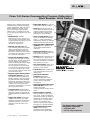
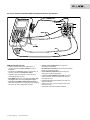
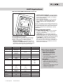
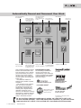
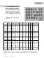
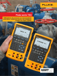
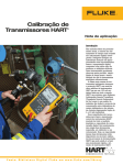
Fluke 740 Series Documenting Process Calibrators:
Ready For Anything Fluke 740 Series Documenting Process Calibrators:
Work Smarter. Work Faster.
Whether you’re calibrating instruments,
troubleshooting a problem or running
routine maintenance, Fluke 740 Series
process calibrators can help you get
the job done faster. It does so many
different tasks, so quickly and so well,
it’s the only process calibrator you need
to carry.
• Bright white display lets you read
• Multifunctional. Calibrate
• Three operating modes Measure,
temperature, pressure, voltage, current, resistance, and frequency. Since
it both measures and sources, you can
troubleshoot and calibrate
all with one rugged tool.
• Powerful, yet easy to use. The
easy-to-follow, menu-driven display
guides you through any task. Programmable calibration routines enable you to create and run automated
as-found/as-left procedures to ensure
fast, consistent, calibrations.
• Records and documents results.
To support your ISO-9000 or regulatory standards, the Fluke 741B, 743B,
and 744 capture your calibration
results, eliminating the need to juggle
a pen and pad in the field. The
RS-232 interface in the Fluke 743B
and 744 lets you transfer the results
to a PC, thus saving the time of having to manually transcribe them when
you return to the shop.
• Supports popular instrumentation
management software. The 743B
and 744 work with the Fluke DPC/
TRACK™ software, and with popular
programs from Honeywell Loveland,
Cornerstone, Yokogawa, Prime Technologies, On-Time Support, and others.
It allows you to create procedures,
instructions, and action lists to deliver
fast, easy documentation.
• Truly hand-held. Small enough to
fit easily into a tool bag and to use in
tight spaces. Runs an entire shift on
a rechargeable NiCd or NiMH battery
pack.
• Rugged and reliable. Overmolded
urethane case stands up to rough
handling in industrial environments.
Calibrators offer one- or two-year
calibration cycles and three-year
warranty.
your results in any kind of light.
• Soft keys provide one-touch ac-
cess to enhanced functions such as
task lists, automated procedures,
scaling, min/max, stepping and
ramping, and review memory.
Source, or simultaneous Measure/
Source, — enable technicians to
troubleshoot, calibrate, or maintain
instrumentation with just one tool.
• Integrated HART communication
capability lets you program and
control HART instrumentation
(744 only).
• Multi-lingual interface displays
instructions in English, French, German, Spanish, and Italian.
• AutoStep allows technicians to set
the calibrator for a delayed start
and a specific sequence of steps, so
it can run unattended as a continuously varying test source.
• User entered values enable users
to capture readings measured or
sourced by other devices.
• Custom units allow readings to be
scaled and displayed in any userdefined units.
• Limit switch calibration
procedures perform fast,
automated calibration of oneand two-point limit switches for
voltage, current, temperature,
and pressure.
• Differential pressure flow instrument calibration routines use a
square root function
to directly calibrate DP flow instruments.
• Built-in algebraic calculator
with four functions — plus square
root—stores, recalls, and performs
calculations required for setting up
instruments or evaluating data in
the field. Use it to set the source
function to a calculated value.
There’s no need to carry a pencil
and paper or a separate calculator.
• Programmable measurement
delay inside automated
procedures permits calibrating
instruments that respond slowly.
2 Fluke Corporation 740 Series Brochure
Two bonus features available
with product registration:
• Transmitter mode
• Bar code entry (except 741B)
Fluke 740 Series Documenting Process Calibrators:
Calibrators as versatile as you are.
The Fluke 740 Calibrators, offered in three models, let
you choose the right set of capabilities for your needs.
• The Fluke 741B offers simultaneous source
and measure capabilities for all common process parameters. Create and execute automated procedures
and automatically capture the results.
• The Fluke 743B offers all the capability of the 741B,
plus adds a serial interface for two-way communication with popular PC-based instrumentation
management applications.
• The Fluke 744 offers all of the capabilities of the
743B, plus the ability to maintain and calibrate
selected HART transmitters without a second tool.
Capability
Source / Measure
Automated procedures
Results capture
Uses all Fluke pressure modules
Transmitter mode
Bar code entry
Serial interface
Data logging
HART communications
Pulsed RTD simulation to 1 ms
NiMH battery with “Gas Gauge” 741B743B 744
•
•
•
•
•
•
•
•
•
•
•
•
•
•
•
•
•
•
•
•
•
•
•
•
•
•
Fluke 744 HART Documenting Process Calibrator:
Get HART-ability.
As more and more process plants begin to take
advantage of smart transmitters, the need for a new
generation of calibrators has emerged — calibrators
that can communicate via industry standard digital
protocols. The 744 combines HART communication
capability with the popular 740 Series Documenting
Process Calibrators to deliver an integrated communicating calibrator. This rugged, reliable tool is ideal for
calibrating, maintaining, and troubleshooting HART
instrumentation. The 744 offers:
• Integrated HART communication functions, permitting you to monitor, control, and calibrate HART
instrumentation.
• Handling of fast pulsed RTD transmitters and PLCs,
with pulses as short as 1 mS.
• NiMH battery with 3500 mA hour life and gas gauge.
The first field calibrator for HART instruments
that’s both powerful and easy to use.
The 744 offers the most complete HART implementation of any process calibrator. The 744:
• Requires no external box or second tool for everyday HART calibration and maintenance.
• Offers fast HART communication.
• Supports popular models of HART transmitters, with
more device-specific command support than any
other HART field calibrator.
• Fully complies with the Data Link Layer of the HART
protocol, including multiple masters, burst mode,
and multi-drop configurations.
• Is easy to update as additional instruments are
added and new HART versions are released.
• Is based on the 743B, the most rugged, reliable
multifunction field calibrator available.
• Is backed by the service and support of the Fluke
organization, a member of the HART Communications Foundation.
The 744 is designed to take on nearly all the day-today tasks you now perform with a separate communicator. In fact, it offers the communication capabilities
of the 275 HART communicator except for the DD
interpreter, which can read command set libraries
from any HART supplier. This is not necessary for daily
HART maintenance.
3 Fluke Corporation 740 Series Brochure
It’s easy to calibrate and maintain HART instrumentation with one powerful tool.
With the 744 DPC, you can:
• Generate precision electrical, temperature, or
pressure signals for analog stimulus or sensor
simulation.
• Simultaneously measure electrical, temperature, or
pressure signals from transmitter output.
• Determine type, manufacturer, model, tag ID by
interrogating HART devices.
• Read HART PV function and smart transmitter digital output while measuring analog mA output.
• Read and write HART configuration functions to
make field adjustments to PV range points, damping,
and other top-level configuration settings.
4 Fluke Corporation 740 Series Brochure
• Change sensor configuration on supported
temperature transmitters.
• Re-label smart transmitters by reading and writing
HART tag and message fields.
• Clone additional transmitters by reading and
storing basic HART configurations.
• Perform automated HART sensor trim and output
trim for selected devices in conjunction with As
Found/As Left tests.
• Perform loop test with simultaneous analog and
digital mA readout.
• Address new, fast, pulsed-excitation smart transmitters and PLCs.
• Control Hart Scientific Dry Block Calibrator.
HART Applications
Fluke 744: The first HART calibrator that is easy to use.
• Common practice commands — provide functions
that are common to many but not all field devices,
for example read multiple variables, set damping
time, or perform loop test
• Device-specific commands — provide functions
that are unique to a particular field device, for
example sensor trim. The 744 supports these
devices:
Today’s 744 supports device-specific instructions for a
variety of popular instruments. Additional support may
be added periodically with a simple software update
available on diskette or via download for a modest
upgrade fee.
Versatile HART protocol support
The 744 supports the commands contained in HART
protocol version 5.7. With 2 MB of memory, the 744
supports a substantial set of HART instructions:
• Universal commands — provide functions that are
implemented in all field devices, for example, read
manufacturer and device type, read primary variable
(PV), or read current output and percent of span
Manufacturer
Pressure Instruments
Temperature Instruments
600T
658T1
ABB/Kent-Taylor
ABB/
Hartmann & Braun
Contrans P,1
AS 800 Series
Endress & Hauser
CERABAR S,
CERABAR M,
DELTABAR S
Foxboro Eckardt
Foxboro/Invensys
TI/RTT201
I/A Pressure
FCX
FCXAZ
FRC
Honeywell
ST3000
STT25T1, STT25H1
Micro Motion
Moore Products
Siemens
1151
2088
3001C
3051, 3051S
SMAR
LD301
I/A Pressure
Yokogawa
3441
3044C
644
3144
3244, 3144P
SITRANS P DS
SITRANS P ES
Viatran
Wika
Coriolis Instruments
TMT 1221, TMT 1821,
TMT 1621
Fuji
Rosemount
HART operating modes supported
• For Point to Point operation, the most commonly
used mode, connects the 744 to a single HART
device in a 4-20 mA loop.
• In Multi-Drop mode, several HART instruments
can be bussed together. The 744 searches for each,
identifies addresses in use, and allows you to select
the instrument for calibration and related operations.
• In Burst Mode, the HART instrument transmits
bursts of data without waiting to be interrogated
by a master unit. The 744 can take transmitters out
of burst mode during test or calibration, then later
restore them to burst mode.
TT3011
UNITRANS
T32H1
EJA
YTA 110, 310 and 320
1
Sensor Trim not supported
5 Fluke Corporation 740 Series Brochure
2000
2000 IS
9701
9712
9739
What’s new in Version 2.5
• Device-specific calibration
support for new instruments:
• Micro Motion 2000, 2000 IS,
9701, 9712 and 9739 coriolis
flow transmitters
• Fuji FCX and FCXA2 pressure and
FRC temperature transmitter
• New features:
• Support for New Hart Scientific dry
blocks: 7103, 9007, 9011, 9023,
9103, 9105, 9107, 9122, 9127, 9132,
9133 and 9150
• Enhanced dry block delay setting for
temperature switch testing
• Switch test without reset
Why use “smart” instrumentation?
Like most process plants, your organization is probably
facing the dual challenges of maximizing productivity
while minimizing maintenance costs. “Smart” digital
transmitters offer superior performance and reliability, while saving time and effort in maintenance and
calibration. Manufacturers of field instruments have
helped accelerate the changeover by offering smart
transmitters at prices nearly as low as analog units.
As digital instruments using the HART protocol quickly
become the standard, communicators and calibrators
are becoming essential everyday tools.
Fluke 789
ProcessMeter™
What is HART?
HART, the Highway Addressable Remote Transducer
protocol, uses a 1200 baud Frequency Shift Keying
(FSK) signal to superimpose digital information on the
conventional 4-20 mA analog signal.
Why use the HART protocol?
HART is an industry standard developed to define the
communications protocol between intelligent field
devices and a control system, HART is the most widely
used digital communication protocol in the process
industry. More than five million HART field instruments
are installed in more than 100,000 plants worldwide.
The HART protocol:
• Is supported by all of the major suppliers of process
field instruments supported by the HART Communication Foundation, an industry-wide non-profit
organization. See the Web site HYPERLINK
http://www.hartcomm.org for information on the
HART standard.
• Preserves present control strategies.
• Allows traditional 4-20 mA signals and digital
communication to share the same two-wire loops.
• Provides important information for installation and
maintenance: Tag IDs, measured values, range and
span data, product information and diagnostics.
• Reduces operation costs by making it easier
to manage and fully utilize “smart” instrument
networks.
The Fluke-789 extends the proven performance of the
evolutionary Fluke-787 and adds many new features
and improvements.
Key New 789 features:
• 24 V loop power supply
• HART mode setting with loop power
(adds 250 ohm resistor)
• 200 % larger dual display
• mA drive up to 1,200 ohms
• Enhanced backlight with (2) brightness settings
• Improved battery power with (4) AA batteries
• 0 to 100 % mA Span Check buttons to toggle from
4 mA to 20 mA
• Infrared I/O serial port compatible with FlukeView
Software
• 5 V measurement capability on the 4 V range for
precise 1 V to 5 V measurements
787 features included in the 789:
• DMM designed to meet 1000 V IEC 1010 CAT III
standards
• Precision 1000 V, 400 mA digital multimeter
Measure ac and dc volts,
ac and dc current, resistance, continuity and frequency
True-rms ac voltage measurement
Frequency measurement to 20 kHz
• 20 mA dc current source/loop calibrator/simulator
Manual Step (100 %, 25 %, Coarse, Fine) plus
Auto Step and Auto Ramp
• Externally accessible battery for easy battery changes
• V overload protection on V, ohms, frequency, mA
(backed up by 440 mA 1000 V fuse)
6 Fluke Corporation 740 Series Brochure
Automatically Record and Document Your Work
Select and schedule Tag
IDs for calibration.
Manage your database
with system utilities.
Examine and analyze
the detailed calibration
histories of your Tag IDs
and instruments.
Import test parameters
from your existing system.
Export calibration results
as delimited ASCII data.
Fluke 700SW DPC/TRACK software
includes an instrumentation database that makes it easy to manage
your instrumentation, create and
schedule tests, load and unload
the 743 or 744, print a variety of
standard reports, and manage calibration data.
DPC/TRACK is available in
English, French, German, Spanish,
and Italian.
Print standard reports automatically. The software assembles
pre-formatted reports from your
database files, saving time and
reducing errors. Reports include
calibration certificates, instruments due for calibration, inventory
characteristics, calibration histories,
calibration procedures, and traceability to instruments touched.
Load selected procedures
to the calibrator, and
unload calibration results
to your PC.
Print a selection of
pre-formatted reports.
Manage your inventory
of Tag IDs and instruments.
Examine and document
the calibration histories
of your test equipment.
Exit to Windows.
Login to one of
four user levels.
Complete user’s manual on-line.
Documentation of results
The scheduling of calibrations,
DocuMint
creation of procedures and
documentation of your calibration
results are facilitated by a number
of instrumentation management
software packages:
Cal Station and Base Station
™
PRM (Plant Resource
Manager) from Yokogawa
Electric Corporation.
Fluke DPC/TRACK™
AMS from Emerson Process
Management, (formerly
Fisher-Rosemount).
On Time Support
Process/Track
All trademarks are the property of their
respective holders.
To see the Fluke 740 Series calibrators in action, call 1 800 44 FLUKE (U.S.),
31 40 2 675 200 (Europe), 1 425 446 5500 (other countries), or your local Fluke
representative for a demo. Visit our Web site: www.fluke.com/Processtools
7 Fluke Corporation 740 Series Brochure
Measurement Function Specifications
DC voltage measurement
DC current measurement
Accuracy (% of reading + % of full scale)
Range (full scale)
1 year
2 years
110.000 mV
0.025 % + 0.015 %
0.05 % + 0.015 %
1.10000 V
0.025 % + 0.005 %
0.05 % + 0.005 %
11.0000 V
0.025 % + 0.005 %
0.05 % + 0.005 %
110.000 V
0.05 % + 0.005 %
0.1 % + 0.005 %
300.00 V
0.05 % + 0.005 %
0.1 % + 0.005 %
Temperature coefficient: (0.001 % reading + 0.0015 % f.s.)/°C
from -10 °C to 18 °C and 28 °C to 50 °C
Input impedance: 5 MΩ
Common mode error: 0.008 % f.s./(Common Mode Volt)
Maximum input voltage: 300 V rms
Accuracy (% of reading + % of full scale)
Range (full scale)
1 year
2 years
30.000 mA
0.01 % + 0.015 %
0.02 % + 0.015 %
110.00 mA
0.01 % + 0.015 %
0.02 % + 0.015 %
Temperature coefficient: (0.001% reading + 0.002 % f.s.)/°C
from -10 °C to 18 °C and 28 °C to 50 °C
Common mode error: 0.01 % f.s./(Common Mode Volt)
Maximum input voltage: 30 V dc
AC voltage measurement
Accuracy (% of reading + counts)
Frequency range
1 year
2 years
20 Hz to 40 Hz
2 % + 10 2 % + 10
40 Hz to 500 Hz
0.5 % + 5
0.5 % + 5
500 Hz to 1 kHz
2 % + 10
2 % + 10
1 kHz to 5 kHz
10 % + 20
10 % + 20
Ranges: 1.1000 V, 11.000 V, 110.00 V, 300.0 V
Specifications apply for 10 % to 100 % of range
Input impedance: 5 MΩ and <100 pF
Input coupling: AC only
Temperature coefficient:
10 % of spec/°C from -10 °C to 18 °C and 28 °C to 50 °C
Maximum input voltage: 300 V rms
Minimum input voltage: 0.5 V above 1 kHz
Resistance measurement
Accuracy (% of reading + ohms)
Range (full scale)
1 year
2 years
11.000 Ω
0.05 % + 50 mΩ
0.075 % + 50 mΩ
110.00 Ω
0.05 % + 50 mΩ
0.075 % + 50 mΩ
1.1000 kΩ
0.05 % + 0.5 Ω 0.075 % + 0.5 Ω 11.000 kΩ
0.1 % + 10 Ω 0.1 % + 10 Ω
Temperature coefficient: (0.01 % f.s. + 2 mΩ)/°C from -10 °C to 18 °C
and 28 °C to 50 °C
Common mode error: 0.005 % f.s./(Common Mode Volt)
Maximum input voltage: 30 V dc
Continuity: Continuous tone < 25 Ω, No tone > 400 Ω
Frequency measurement
Accuracy
Range
1 year
2 years
1.00 Hz to 109.99 Hz
0.05 Hz
0.05 Hz
110.0 Hz to 1099.9 Hz
0.5 Hz
0.5 Hz
1.100 kHz to 10.999 kHz
0.005 kHz
0.005 kHz
11.00 kHz to 50.00 kHz
0.05 kHz
0.05 kHz
For frequencies < 109.99 Hz, specification applies for signals with
slew rates > 5 V/ms
Minimum amplitude for Hz measurement: (Squarewaves) 1 Hz to
1 kHz, 300 mV p-p; 1 kHz to 30 kHz, 1.4 V p-p; > 30 kHz, 2.8 V p-p
Maximum input: 1 Hz to 1 kHz, 300 V rms; > 1 kHz, 30 V rms
Input impedance: 5 MΩ
Sourcing (Simulation) Function Specifications
DC voltage output
Resistance sourcing
Accuracy (% of output + % of full scale)
Range (full scale)
1 year
2 years
110.000 mV
0.01 % + 0.005 %
0.015 % + 0.005 %
1.10000 V
0.01 % + 0.005 %
0.015 % + 0.005 %
15.0000 V
0.01 % + 0.005 %
0.015 % + 0.005 %
Temperature coefficient: (0.001 % output + 0.001 % f.s.)/°C
from -10 °C to 18 °C and 28 °C to 50 °C
Maximum output current: 10 mA
Loading: (0.001 % f.s. +1 µV)/mA
Common mode error: 0.008 % f.s./(Common Mode Volt)
Maximum input voltage: 30 V dc
Accuracy (% of output + ohms)
Range (full scale)
1 year
2 years
11.000 Ω
0.01 % + 20 mΩ
0.02 % + 20 mΩ
110.00 Ω
0.01 % + 40 mΩ
0.02 % + 40 mΩ
1.1000 kΩ
0.02 % + 0.5 Ω
0.03 % + 0.5 Ω
11.000 kΩ
0.03 % + 5 Ω
0.04 % + 5 Ω
Temperature coefficient: 0.01 % f.s./°C from -10 °C to 18 °C and
28 °C to 50 °C
Maximum and minimum current through source resistance:
Maximum
Minimum
11 Ω range: 3 mA dc
0.1 mA dc
110 Ω range: 3 mA dc
0.1 mA dc
1.1 kΩ range: 3 mA dc
0.01 mA dc
11 kΩ range: 1 mA dc
0.01 mA dc
Common mode error: 0.008 % f.s./(Common Mode Volt)
Maximum input voltage: 30 V dc
DC current output
Accuracy (% of output + % of full scale)
Range (full scale)
1 year
2 years
22.000 mA
0.01 % + 0.015 %
0.02 % + 0.015 %
Current sink (sim-
0.02 % + 0.03 %
0.02 % + 0.03 %
ulate transmitter)
Specification applies from 2 to 22 mA; below 2 mA typical accuracy is
0.15 % of full scale
Maximum burden voltage: 24 V
Temperature coefficient: (0.003 % output + 0.003 % f.s.)/°C
from -10 °C to 18 °C and 28 °C to 50 °C
Common mode error: 0.008 % f.s./(Common Mode Volt)
Maximum input voltage: 30 V dc
8 Fluke Corporation 740 Series Brochure
Frequency sourcing
Range
0.00 to 10.99 Hz
11.00 Hz to 109.99 Hz
110.0 Hz to 1099.9 Hz
1.100 kHz to 21.999 kHz
22.000 kHz to 50.000 kHz
Accuracy
1 year
0.01 Hz
0.1 Hz
0.1 Hz
0.002 kHz
0.005 kHz
2 years
0.01 Hz
0.1 Hz
0.1 Hz
0.002 kHz
0.005 kHz
Waveforms: Squarewave with 50 % duty cycle, sinewave
Amplitude: 0.1 to 10 V p-p
Amplitude accuracy: 3 % of output + 0.5 % of f.s., 1 to 1099 Hz;
10 % of output + 0.5 % of f.s., 1.1 to 10.9 kHz; 30 % of output +
0.5 % f.s., 11 to 50 kHz
Maximum input voltage: 30 V dc
Temperature Measurement and
Simulation Specifications
Temperature, Thermocouples
Temperature, RTDs
Accuracy
Measure
1 year
2 years
Source
1 year
2 years
Type and range
10 Ω Cu (427)
-100 to 0 °C
2 °C
2 °C
1 °C
1 °C
0 to 260 °C
2 °C
2 °C
1 °C
1 °C
100 Ω Pt (3916)
-200 to -190 °C
0.3 °C
0.4 °C
0.3 °C
0.4 °C
-190 to 0 °C
0.3 °C
0.4 °C
0.1 °C
0.2 °C
0 to 630 °C
0.5 °C
0.8 °C
0.2 °C
0.4 °C
100 Ω Pt (3926)
-200 to 0 °C
0.3 °C
0.4 °C
0.1 °C
0.2 °C
0 to 630 °C
0.5 °C
0.8 °C
0.2 °C
0.4 °C
100 Ω Pt (385) -200 to 0 °C
0.3 °C
0.5 °C
0.1 °C
0.2 °C
0 to 400 °C
0.5 °C
0.8 °C
0.2 °C
0.4 °C
400 to 800 °C
0.8 °C
1.0 °C
0.4 °C
0.5 °C
200 Ω Pt (385) -200 to 0 °C
0.3 °C
0.5 °C
0.1 °C
0.2 °C
0 to 400 °C
0.5 °C
0.8 °C
0.2 °C
0.4 °C
400 to 630 °C
0.8 °C
1.0 °C
0.4 °C
0.5 °C
500 Ω Pt (385)
-200 to 0 °C
0.3 °C
0.5 °C
0.1 °C
0.2 °C
0 to 400 °C
0.5 °C
0.8 °C
0.2 °C
0.4 °C
400 to 630 °C
0.8 °C
1.0 °C
0.4 °C
0.5 °C
1000 Ω Pt (385)
-200 to 0 °C
0.3 °C
0.5 °C
0.1 °C
0.2 °C
0 to 400 °C
0.5 °C
0.8 °C
0.2 °C
0.4 °C
400 to 630 °C
0.8 °C
1.0 °C
0.4 °C
0.5 °C
120 Ω Ni (672)
-80 to 260 °C
0.3 °C
0.4 °C
0.1 °C
0.2 °C
For 2-wire and 3-wire measurements add 0.4 °C
Sensor inaccuracies not included
Resolution: 0.1 °C, except 1 °C for 10 Ω Cu
Temperature coefficient: 0.02 °C/°C from -10 °C to 18 °C and
28 °C to 50 °C
Maximum input voltage: 30 V dc
Maximum input current for RTD Source function:
10 Ω RTD 8 mA dc
100, 120 Ω RTDs 8 mA dc*
200, 500, 1000 Ω RTDs 1 mA dc
741B*, 743B*, 744: Addresses pulsed transmitters and PLCs with
pulses as short as 1 ms
* For 741B serial number 7935XXXX and greater.
For 743B serial number 7940XXXX and greater.
Otherwise, 3 mA and 100 ms.
How to compare calibrators based on specifications.
Analyzing specifications can be com• Temperature. Fluke process calibrator
plex. To get a true picture of calibrator
specs reflect performance from
performance, you should be aware of
18 ° to 28 °C. Compensation factors
the key components of a specification
are provided to permit specified use
and how to interpret them. Specificaof the calibrators over a wide -10 ° to
tions must be carefully considered
50 °C range.
when comparing calibrators from
Allowance for traceability. Fluke
•
different vendors. The most important
specs are not relative specs, but total
components of a process calibrator
specs, including an allowance for
specification are:
uncertainty of standards that provide
Reference
uncertainty.
Performance
•
traceability to national standards.
of a calibrator at 23 °C + 3°C at the
Confidence level. Fluke uses a con•
time it is verified by the manufacservative 95 % confidence level when
turer. This specification does not
setting specifications, increasing your
include the effects of time and
confidence that your calibrator will
temperature, two of the largest comremain in spec for its stated calibration
ponents of calibrator error.
interval.
• Time. Fluke 740 Series calibrators For more information, refer to the application
are delivered with both one-year
note “Understanding Specifications For Process
and two-year specs, to limit your
Calibrators.”
calibration support costs. You choose
your cal interval based upon the
performance you need.
9 Fluke Corporation 740 Series Brochure
Accuracy
Measure
Source
1 year
2 years
1 year
2 years
Type and range
E
-250 to -200 °C
1.3 °C
2.0 °C
0.6 °C
0.9 °C
-200 to -100 °C
0.5 °C
0.8 °C
0.3 °C
0.4 °C
-100 to 600 °C
0.3 °C
0.4 °C
0.3 °C
0.4 °C
600 to 1000 °C
0.4 °C
0.6 °C
0.2 °C
0.3 °C
N
-200 to -100 °C
1.0 °C
1.5 °C
0.6 °C
0.9 °C
-100 to 900 °C
0.5 °C
0.8 °C
0.5 °C
0.8 °C
900 to 1300 °C
0.6 °C
0.9 °C
0.3 °C
0.4 °C
J
-210 to -100 °C
0.6 °C
0.9 °C
0.3 °C
0.4 °C
-100 to 800 °C
0.3 °C
0.4 °C
0.2 °C
0.3 °C
800 to 1200 °C
0.5 °C
0.8 °C
0.2 °C
0.3 °C
L
-200 to -100 °C
0.6 °C
0.9 °C
0.3 °C
0.4 °C
-100 to 800 °C
0.3 °C
0.4 °C
0.2 °C
0.3 °C
800 to 900 °C
0.5 °C
0.8 °C
0.2 °C
0.3 °C
K
-200 to -100 °C
0.7 °C
1.0 °C
0.4 °C
0.6 °C
-100 to 400 °C
0.3 °C
0.4 °C
0.3 °C
0.4 °C
400 to 1200 °C
0.5 °C
0.8 °C
0.3 °C
0.4 °C
1200 to 1372 °C
0.7 °C
1.0 °C
0.3 °C
0.4 °C
T
-250 to -200 °C
1.7 °C
2.5 °C
0.9 °C
1.4 °C
-200 to 0 °C
0.6 °C
0.9 °C
0.4 °C
0.6 °C
0 to 400 °C
0.3 °C
0.4 °C
0.3 °C
0.4 °C
U
-200 to 0 °C
0.6 °C
0.9 °C
0.4 °C
0.6 °C
0 to 600 °C
0.3 °C
0.4 °C
0.3 °C
0.4 °C
B
600 to 800 °C
1.3 °C
2.0 °C
1.0 °C
1.5 °C
800 to 1000 °C
1.0 °C
1.5 °C
0.8 °C
1.2 °C
1000 to 1820 °C
0.9 °C
1.3 °C
0.8 °C
1.2 °C
R
-20 to 0 °C
2.3 °C
2.8 °C
1.2 °C
1.8 °C
0 to 100 °C
1.5 °C
2.2 °C
1.1 °C
1.7 °C
100 to 1767 °C
1.0 °C
1.5 °C
0.9 °C
1.4 °C
S
-20 to 0 °C
2.3 °C
2.8 °C
1.2 °C
1.8 °C
0 to 200 °C
1.5 °C
2.1 °C
1.1 °C
1.7 °C
200 to 1400 °C
0.9 °C
1.4 °C
0.9 °C
1.4 °C
1400 to 1767 °C
1.1 °C
1.7 °C
1.0 °C
1.5 °C
C
0 to 800 °C
0.6 °C
0.9 °C
0.6 °C
0.9 °C
800 to 1200 °C
0.8 °C
1.2 °C
0.7 °C
1.0 °C
1200 to 1800 °C
1.1 °C
1.6 °C
0.9 °C
1.4 °C
1800 to 2316 °C
2.0 °C
3.0 °C
1.3 °C
2.0 °C
XK
-200 to -100 °C
0.5 °C
0.7 °C
0.4 °C
0.5 °C
-100 to 800 °C
0.4 °C
0.6 °C
0.3 °C
0.4 °C
BP
0 to 800 °C
0.8 °C
1.1 °C
0.4 °C
0.5 °C
800 to 1600 °C
1.2 °C
1.8 °C
0.5 °C
0.8 °C
600 to 2500 °C
2.2 °C
3.3 °C
0.9 °C
1.4 °C
Sensor inaccuracies not included
Accuracy with external cold junction; for internal junction add 0.2 °C
Resolution: 0.1 °C
Temperature scale: ITS-90 or IPTS-68, selectable
Compensation: ITS-90 per NIST Monograph 175 for E, N, J, K, T, B, R,
S thermocouples; IPTS-68 per IEC 584-1 for E, J, K, T, B, R, S thermocouples; IPTS-68 per DIN 43710 for L, U thermocouples
Temperature coefficient: 0.05 °C/°C from -10 °C to 18 °C and
28 °C to 50 °C
Common mode error: 0.01 °C/(Common Mode Volt)
Maximum input voltage: 30 V dc
Note: When simulating temperature in As Found/As Left procedures,
steps may be either linear by temperature or linear by mV potential.
Pressure Specifications
The Fluke family of 29 pressure modules:
Covers virtually any pressure application including
gage, differential, dual (compound), absolute, and
vacuum.
• Display pressure readings in any of 10 different
pressure units you specify in the calibrator setup.
• Rugged urethane molded cases protect the modules
from rough handling and harsh conditions.
• Features internal temperature compensation from
O° to 50 °C for full-accuracy performance.
Includes
NIST-traceable calibration certificate.
•
• Modules can be calibrated locally, helping to
control costs.
Pressure module specifications (all specifications in % of full span. Specifications reflect a confidence interval of 95%.)
Reference
High2
side
Range/
Range (approx)/ uncertainty Stability Temperature
Total1
Model
Resolution
Resolution
(23 ± 3 ºC) (1 year)
(0 to 50 ºC) uncertainty media
Low2
Max overside
Fitting
pressure
media material (x nominal)
Differential
FLUKE-700P00 1 in. H2O/0.001
FLUKE-700P01 10 in. H2O/0.01
FLUKE-700P02 1 psi/0.0001
FLUKE-700P22 1 psi/0.0001
FLUKE-700P03 5 psi/0.0001
FLUKE-700P23 5 psi/0.0001
FLUKE-700P04 15 psi/0.001
FLUKE-700P24 15 psi/0.001
0.25 kPa/0.0002
2.5 kPa/0.002
6900 Pa/0.7
6900 Pa/0.7
34 kPa/0.001
34 kPa/0.001
103 kPa/0.01
103 kPa/0.01
0.300
0.200
0.150
0.100
0.050
0.025
0.025
0.025
0.025
0.050
0.070
0.020
0.020
0.010
0.010
0.010
0.025
0.050
0.080
0.030
0.030
0.015
0.015
0.015
0.350
0.300
0.300
0.150
0.100
0.050
0.050
0.050
Dry
Dry
Dry
316 SS
Dry
316 SS
Dry
316 SS
Dry
Dry
Dry
Dry
Dry
Dry
Dry
Dry
316 SS
316 SS
316 SS
316 SS
316 SS
316 SS
316 SS
316 SS
30x
3x
3x
3x
3x
3x
3x
3x
207 kPa/0.01
690 kPa/0.07
2070 kPa / 0.1
3400 kPa/0.1
6900 kPa/0.7
10 MPa/0.001
0.025
0.025
0.025
0.025
0.025
0.025
0.010
0.010
0.010
0.010
0.010
0.010
0.015
0.015
0.015
0.015
0.015
0.015
0.050
0.050
0.050
0.050
0.050
0.050
316 SS
316 SS
316 SS
316 SS
316 SS
316 SS
N/A
N/A
N/A
N/A
N/A
N/A
316 SS
316 SS
316 SS
316 SS
316 SS
316 SS
3x
3x
3x
3x
3x
2x
0.050
0.050
0.050
0.050
0.010
0.010
0.010
0.010
0.010
0.010
0.010
0.010
0.070
0.070
0.070
0.070
316 SS
316 SS
316 SS
316 SS
N/A
N/A
N/A
N/A
316 SS
316 SS
316 SS
316 SS
3x
3x
3x
3x
0.040
0.040
0.015
0.015
0.015
0.015
0.070
0.070
316 SS
316 SS
Dry
Dry
316 SS
316 SS
3x
3x
0.150
0.040
0.025
0.025
0.025
0.040
0.025
0.015
0.010
0.010
0.010
0.015
0.025
0.015
0.015
0.015
0.015
0.015
0.200
0.070
0.050
0.050
0.050
0.070
316 SS
316 SS
316 SS
316 SS
316 SS
316 SS
Dry
Dry
Dry
N/A
N/A
N/A
316 SS
316 SS
316 SS
316 SS
316 SS
316 SS
3x
3x
3x
3x
3x
3x
0.050
0.050
0.050
0.010
0.010
0.010
0.020
0.020
0.020
0.080
0.080
0.080
C276
C276
C276
N/A
N/A
N/A
C276
C276
C276
2x
2x
1.5x
Gage
FLUKE-700P05
FLUKE-700P06
FLUKE-700P27
FLUKE-700P07
FLUKE-700P08
FLUKE-700P09
30 psi/0.001
100 psi/0.01
300 psi / 0.01
500 psi/0.01
1000 psi/0.1
1500 psi/0.1
Absolute (not compatible with Fluke 701 or 702)
FLUKE-700PA3
FLUKE-700PA4
FLUKE-700PA5
FLUKE-700PA6
5 psi/0.0001
15 psi/0.001
30 psi/0.001
100 psi/0.01
34 kPa/0.001
103 kPa/0.01
207 kPa/0.01
690 kPa/0.07
Vacuum (not compatible with Fluke 701 or 702)
FLUKE-700PV3
FLUKE-700PV4
-5 psi/0.0001
-15 psi/0.001
-34 kPa/0.001
-103 kPa/0.01
Dual
FLUKE-700PD2 ±1 psi/0.0001
±6900 Pa/0.7
FLUKE-700PD3 ±5 psi/0.0001
±34 kPa/0.001
FLUKE-700PD4 ±15 psi/0.001
±103 kPa/0.01
FLUKE-700PD5 -15/30 psi/0.001 -100/207 kPa/0.01
FLUKE-700PD6 -15/100 psi/0.01 -100/690 kPa/0.07
FLUKE-700PD7 -15/200 psi/0.01 -100/1380 kPa/0.1
High
FLUKE-700P29
FLUKE-700P30
FLUKE-700P31
3000 psi/0.1
5000 psi/0.1
10000 psi/1
20.7 M Pa/0.001
34 M Pa/0.001
69 M Pa/0.007
1
Total uncertainty, one year for temperature range 0 °C to +50 °C. Total uncertainty, 1.0% of full span for temperature range -10 °C to 0 °C. For P00 module only, compensated
temperature range is 15 ° to 35 °C.
2
“Dry” indicates dry air or non-corrosive gas as compatible media. “316 SS” indicates media compatible with Type 316 Stainless Steel. “C276” indicates media compatible with
Hastelloy C276.
rated. Metric adapter(s):
Use of pressure zero is required prior to measurement or source. Maximum overpressure specification includes common mode pressure. Modules are
1/4˝ NPT female to male BSP/ISO 1/4-19, tapered thread, included with all modules except P29, P30, and P31. Effective October 1996, all modules include a NIST traceable certificate
and test data.
10 Fluke Corporation 740 Series Brochure
General Specifications
Data log function (except 741B)
Measure functions: Voltage, current, resistance,
frequency, temperature, pressure
Reading rate: 1, 2, 5, 10, 20, 30, or 60 readings per
minute
Maximum record length: 8000 readings
(7980 for 30 or 60 readings per minute)
Ramp function
Source functions: Voltage, current, resistance,
frequency, temperature
Rate: 4 steps/second
Trip detect: Continuity* or voltage
*Continuity detection not available when sourcing current
Loop power function
Voltage: Selectable, 24 V or 28 V
Accuracy: 5 %
Maximum current: 22 mA, short-circuit protected
Maximum input voltage: 30 V dc
Note: 250 Ω series resistance is automatically supplied whenever loop power is
enabled on 744.
HART modem interface (744 only)
Maximum input voltage: 30 V dc
Environmental specifications
All calibrator specifications apply from +18 °C to
+28 °C unless stated otherwise.
Operating temperature: -10 °C to 50 °C, (-20 °C typical
except for frequency and ac voltage measurement)
Storage temperature: -20 °C to 60 °C
Operating altitude: 2800 m above mean sea level
(9186 ft)
90-day specifications: The standard specification
intervals for the 740 Series are 1 and 2 years. Typical 90-day measurement and source accuracy can be
estimated by dividing the one year “% of reading” or
“% of output” specifications by 2. Floor specifications,
expressed as “% of f.s.” or “counts” or “ohms” remain
constant.
Power: Internal battery pack NiCd, 7.2 V, 1700 mAh;
NiMH (744 only) 7.2 V, 3500 mAh
Battery Life: Typical usage, >8 hours
Dimensions: 130 mm x 236 mm x 61 mm
(5.1 in x 9.3 in x 2.4 in)
Weight: 1.4 kg (3 lb, 1 oz)
Side Port Connections:
• Pressure module connector
• RS-232 connector (743B and 744) to interface to
your PC
• Connection for optional battery eliminator
Safety: Complies with CAN/CSA C22.2 No 1010.1-92,
ANSI/ISA S82.01-1994, UL3111, and EN610-1:1993.
Data Storage Capacity:
Fluke 741B—1 day of calibration results
Fluke 743B and 744—1 week of calibration results
Ordering Information
FLUKE-741B Documenting Process Calibrator
FLUKE-743B Documenting Process Calibrator
FLUKE-744 Documenting Process Calibrator-HART
Included with the Fluke 740 Series:
Type TL224 Industrial Test Leads (two sets), AC220
Test Clips (2 sets), TP220 Test Probes (1 set), Battery
Pack, Battery Charger, serial port cable (except 741B),
HART communications cable (744 only), DPC/TRACK
Sample with free PC communication utility software
(except 741B), Instruction Manual, NIST-traceable calibration report and data, three-year warranty.
FLUKE-700SW DPC/TRACK Software (for use with
Model 743B or 744 calibrators)
Included with DPC/TRACK software:
Software media, Instruction Manual, Serial Port Cable,
DB9 to DB25 (9 pin to 25 pin) Adapter.
FLUKE-700 Pxx Pressure Modules
Included with each Fluke Pressure Module:
BP-ISO Adapter(s) (except with P29 - P31), Instruction
Sheet, NIST traceable calibration report and data,
one-year warranty.
FLUKE-744 Upgrade
Fluke-744V20
HART Upgrade Revision 2.5
Accessories
Fluke-700PMP
Fluke-700LTP-1
Fluke-700PTP-1
Fluke-700HTP-1
Fluke-700HTH-1
Fluke-700PRV-1
Fluke-700-IV
applications)
Fluke-700PCK
Fluke-700BCW
Fluke-700TC1
Fluke-700TC2
80T-IR
80PK-IR
BE9005
BC7217
BP7217
BP7235
C700 C781
C789
C75
Pressure Pump; 100 psi/7 bar
Low Pressure Test Pump
Pneumatic Test Pump;
400 psi/40 bar
Hydraulic Test Pump;
10,000 psi/700 bar
Hydraulic Test Hose
Pressure Relief Valve Kit for HTP
Current Shunt (for mA/mA
Pressure Calibration Kit
Bar Code Wand
TC Mini-Plug Kit, 9 types
TC Mini-Plug Kit, JKTERS
Infrared Probe
Infrared Probe
Battery Eliminator
Battery Charger
NiCd Battery Pack
NiMH Battery Pack
Hard Carrying Case
Soft Carrying Case
Soft Carrying Case
Test Lead Case
Fluke. Keeping your world up and running.®
Fluke Corporation
PO Box 9090,
Everett, WA 98206 U.S.A.
Fluke Europe B.V.
PO Box 1186, 5602 BD
Eindhoven, The Netherlands
©2004-2008 Fluke Corporation. Specifications subject to change without
notice. Printed in U.S.A. 6/2008 1263323 B-EN-N Rev J
Modification of this document is not permitted without written permission
from Fluke Corporation.
11 Fluke Corporation 740 Series Brochure