1
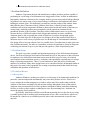
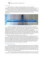
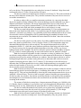
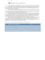
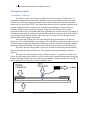
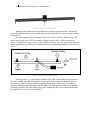
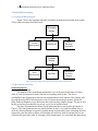
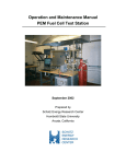
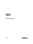
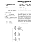
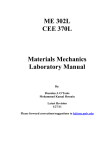
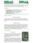
Bow Measurement Device for a Window Lineal Volume I: Design Report University of Minnesota Department of Mechanical Engineering ME 4054W – Senior Design Spring 2013 Design Show – May 9, 2013 Sponsored By: Andersen Windows Course Advisors: Design Team: Industry Advisors: Prof. Brad Bohlmann Adam Wrucke Graham Duthie Prof. Will Durfee Brendan Schatz John Lilla Kern Lik Tan Nick Murgic Sean Poluha 2 Bow Measurement Device for a Window Lineal Executive summary Andersen Corporation is a manufacturer of fenestration products. The reliability of their products in harsh or extreme weather conditions is very important. A key performance metric is deformation, termed bow. A component that is known to bow and cause problems is the window lineal, which is the portion of the frame that holds the glass. Large differences in outside and inside temperatures, high winds and other environmental factors can cause bow in lineals. If the bow is too large a loss of contact with weather stripping may result in air and water leakage, a very undesirable outcome for Andersen. The main purpose of the project was to design a window lineal bow measurement device to meet Andersen’s needs. After gathering and reviewing customer product specifications the team decided that the best way to meet them all was with two devices. One version is portable to be used in a lab setting or carried to the field for one-time measurements. The second version is permanently affixed to windows at long-term outdoor test stations to collect bow measurement data for months up to a year at a time. The devices had to adhere to the same sensor requirements, meaning they had to have the same resolution, accuracy, range, and repeatability. They also both have to be able to measure the full range of Andersen product sizes. There were variations in the required cost and setup time based on usage. The portable device utilized a solid bar sliding in a slot design for adjustability. A short range, mid range and long range version of the portable design were able to fulfill the customer needs for adjustability. Figure 1: T-Slot Adjustable Portable Bow Measurement Device The permanent device used a cable in tension between equal height towers design. Two towers will be mounted on the lineal on each end with the sensor mounted in the middle. A stainless steel cable runs through holes in the towers and an adapter, which is connected to the sensor. A spring is added in line with the tensioned cable to maintain tension in all conditions. Figure 2: Permanent Bow Measurement Device The cost, setup time, and mass of both devices met the product specification requirements. The sensors chosen by the team were unable to meet the resolution or repeatability requirements due to cost restraints. Our advisor confirmed that the sensors are still accurate enough to be used for general testing. Cost analysis of the designs indicated the permanent device is 75% more expensive than the current device and the portable device is 95% less expensive. Both devices are under the budgeted cost. For tests that require higher resolution measurements, the team suggests Andersen utilize higher accuracy (more expensive) sensors such as the Mitutoyo sensor used on the current device. 3 Bow Measurement Device for a Window Lineal Team Contributions The following is a listing of the individual contributions to the project from each team member. Contributions of Adam Wrucke: Evaluation plan write up Functional description write up Created Gantt chart and WBS Setup time testing Portable repeatability testing Final report volume I and II Contributions of John Lilla: Patent searches Concept generating Load calculations on portable Worked on prototypes Created design show poster Advantages and disadvantages section Editor volume I and II Final report volume I and II Contributions of Brendan Schatz: Sensor research/ datasheet comparison Product design specification (volume I) Edit/Add material to various sections in both volume I, II, and user manual Repeatability and sensor calibration testing Design and built T-slot portable device CAD drawing T-slot portable device and related parts CAD drawing and rapid prototype of sensor housing (portable device) CAD drawing and rapid prototype of constant force spring concept Manufacturing plan and bill of materials Tension calculation for permanent device Manufacture of PBC portable version Contributions of Kern Lik Tan: SOW and PDS Sensor research Raw materials ordering Moment inertia calculations Mid semester presentation slides Concept generating and sketching 4 Bow Measurement Device for a Window Lineal Cost analysis Setup time evaluation report Executive summary Arduino coding Processing coding (Graphing software) Final report volume I and II Created CAD model for sensor Contributions of Nick Murgic: Site visit slides Mid semester presentation slides Machining of prototypes Machining of calibration block and sensor calibration Annotated bibliography Portable device description Portable and permanent CAD drawings Bill of materials Portable device selection and strength calculations Reports review and modification Andersen user manual Contributions of Sean Poluha: SOW and PDS Site visit slides WBS and Gantt chart Mid semester presentation slides Worked on team poster Technical review Sensor requirements write up General report revisions Setup time testing Table of Contents 1 Problem Definition..................................................................................................................................... 6 1.1 Problem Scope .................................................................................................................................... 6 1.2 Technical Review................................................................................................................................ 6 1.2.1 Background .................................................................................................................................. 6 1.2.2 Prior Art ....................................................................................................................................... 7 1.3 Design Requirements .......................................................................................................................... 7 2 Design Description................................................................................................................................... 11 2.1 Summary of Design .......................................................................................................................... 11 2.2 Detailed Description ......................................................................................................................... 13 2.2.1 Functional Block Diagram ......................................................................................................... 13 2.2.2 Description of Function ............................................................................................................. 13 2.3 Additional Uses................................................................................................................................. 16 3 Evaluation ............................................................................................................................................. 17 3.1 Evaluation Plan ................................................................................................................................. 17 3.2 Evaluation Results ............................................................................................................................ 18 3.2.1 Sensor Requirements.................................................................................................................. 18 3.2.2 Setup Time Requirement ........................................................................................................... 19 3.2.3 Mass Requirement...................................................................................................................... 19 3.2.4 Operating Conditions Requirement............................................................................................ 20 3.3 Discussion ......................................................................................................................................... 20 3.3.1 Strengths and Weakness............................................................................................................. 20 3.3.2 Next Steps .................................................................................................................................. 21 6 Bow Measurement Device for a Window Lineal 1 Problem Definition Andersen Corporation designs and manufactures window and door products capable of performing in a wide range of environments over long periods of time. In order to maintain the high quality Andersen is known for, the company needs to prevent water and air leakage through its products. One major cause of air or water leakage is deflection or deformation in the frame holding the window glass. This deflection is termed bow and the portion of the window frame that holds the glass is known as a lineal. Window lineal bow is caused by harsh weather conditions such as large temperature differences between the inside and outside of the house or strong winds. Andersen products must completely seal the outside environment for the guaranteed lifetime of their products. Thus they need a reliable and accurate way to precisely measure the bow of different window lineal designs and materials in various conditions. Andersen must be able to quantify the extent of lineal bow in order to design high quality products. The main objective of this project is to design a device that measures lineal bow or deflection across a wide variety of product sizes in a broad range of environmental conditions. Our design offers a two part solution. One is a portable device for technicians to make quick onetime field measurements. The other is a permanent version to be attached to a lineal at long-term weathering test stations for up to a year and provide signals to a Data Acquisition System. 1.1 Problem Scope The goal is to create a portable and permanent prototype of our deflection measurement device. Our team will design, build, and test functional devices for the purpose of data collection for Andersen. Our deflection measurement sensor must be able to meet a variety of technical specifications such as minimum accuracy, resolution, and repeatability requirements over a large range of operating temperatures. There is a cost limitation to make the devices feasible and attractive to Andersen. Many other design factors were considered and are documented further in this report. Our team is also responsible for creating an operating manual that details the setup, calibration and operation of both devices. 1.2 Technical Review 1.2.1 Background Andersen Window’s products are subject to a wide range of environmental conditions. In particular, extreme temperature and humidity may cause their products to bow. If the bow is severe enough, the weather stripping on a window or door may fail to make contact with the window or door frame resulting in air and moisture leakage through the frame of the product. Andersen aims to monitor the bow of their products in both their indoor controlled weathering facilities as well as at their outdoor weathering test sites. By monitoring bow, Andersen can ensure the quality of their products. Specifically, Andersen would like two different measuring devices; the first device being a portable option used for making quick measurements of bow, and a second device which can be attached to a lineal over an extended period of time to take measurements in specific time intervals. 7 Bow Measurement Device for a Window Lineal 1.2.2 Prior Art Since this issue is very specific to fenestration products, there is currently no commercially available device capable of measuring the bow of windows and doors. The devices currently in use by Andersen were also designed and manufactured by Andersen Engineers. The current device is shown in Figure 1 below. It consists of an aluminum extrusion with one cylindrical brass peg secured to each end. At the center of the device, there is a collar where a Mitutoyo 575 series linear potentiometer can be inserted and secured to take bow measurements. Figure 1: Current Measurement Device Used by Andersen Windows The bow measuring process requires first determining the approximate length of the window or door to be measured. The measurement device is then selected to be as close to the length of the lineal as possible. Andersen’s test facility uses aluminum extrusions of 50 different lengths ranging from 0.5 to 2.5 meters. After the correct length device is selected the potentiometer is fastened to a hole in the aluminum extrusions by a hand tightened screw. The potentiometer is then calibrated by placing the brass pegs flat against a steel calibration rail and zeroing the digital display of the sensor. The device is then brought to the lineal to be measured. The brass pegs are held securely against the ends of the lineal, and an output on the potentiometer displays the deflection at the center of the lineal. There are many issues with the current devices that Andersen would like to be resolved with a new design. The current devices can only be used for taking measurement of one size lineal at a time and may require multiple workers to take a measurement depending on the length of the lineal. Another issue is that there are currently 50 different measuring devices needed to measure all the different sized products Andersen manufactures. Having so many devices takes up a lot of storage space and is not cost efficient. It is especially inconvenient for fieldwork where many sizes need to be carried to windows in test stations. 1.3 Design Requirements Our design problem has been split into two separate products after interviewing both our advisor and the key customer for the product; the technician that will use the device. A portable lineal bow measurement device will be used on site and various research centers, where only one measurement will be taken at a time. A permanent design will also be developed that can be set up for up to a year at Andersen’s long term weathering test stations. The two devices share some design requirements, but on others they differ. The devices must both have a deflection measurement range from -25 to 25mm [2]. This requirement was determined from the maximum linear bow that has been measured as relayed to 8 Bow Measurement Device for a Window Lineal us by our advisor. This magnitude bow may take place in some of Andersen’s large doors and corresponds to bow of 25 mm [1] into and out of a house. The devices must have a displacement resolution of 0.02 mm [2]. This is the resolution of the device that Andersen currently uses. They want the resolution of any new device to meet or exceed the current device. In order to achieve this very small measurement resolution it is a necessity that both devices be capable of being calibrated. The current technology must be calibrated every time a different sized lineal is measured. The design requirement for our device is that it only be calibrated once for every batch of measurements [1]. For the portable device this means once before going out in the field and for the permanent device once before it is setup. The devices must both produce repeatable measurements [2]. If two measurements are taken at the same lineal location within a very small time span, the results should be the same. Andersen’s current device produces very repeatable results when calibrated and our device must also meet this criterion. Repeatability will be quantified using the standard deviation of ten measurements on a test lineal. The standard deviation should be less than 3 times the resolution or less than 0.06 mm. The devices must operate in a wide variety of weather conditions that will be faced in the field. They must be operable from -30 to 85 degrees Celsius [2]. This temperature range was determined through interviews with our advisor. The current measurement device fails at temperatures below 0 C, which has caused Andersen problems when being used in the winter [1]. The devices may also be exposed to high temperatures since they will be very close to window lineals in direct sunlight. The devices must also operate in relative humidity as high as 95% [2], which is common particularly in some south-eastern states in Andersen’s market. Both devices must be adjustable in order to measure a variety of window sizes. One of our advisors main problems with the current device is that numerous different sizes of aluminum extrusions must be used to measure different size windows. Interviewing our advisor as well as looking through Andersen’s product catalog allowed us to determine that our device must be capable of measuring devices from 0.5 to 2.5 meters [2]. Our interviews also allowed us to determine that 3 different portable device sizes (short, medium and long) are acceptable. It will reduce the total number of devices by over 80%, while still allowing enough rigidity in the device to make accurate measurements. Both of the devices must have small mounting feet in order to attach or connect to narrow lineals that may also be located in tight spaces. A mounting foot width of 13 mm or less is our design goal [2]. This goal was determined by observing the current measurement device in use at Andersen’s research center. The device had to measure a narrow lineal that was surrounded on all sides by other test windows. Our advisor would also like the overall profile of the permanent measuring device to be minimized so that it does not block the sun and thus influence the bow occurring in the window. The sensors of both devices must have a long measurement lifespan, over 100,000 cycles [1]. Window lineals in Andersen’s test facilities may cycle through many different bow values in each direction in one day. Additionally the permanent device will be in place for up to a year [1]. The devices must both minimize any electric power used as they will both be used and located in remote areas where the only source for power will be batteries [2]. The design requirement to meet this goal is power usage of less than 50 milli-watts. Both of the devices must weigh less than 2 kg [1]. This design criterion was determined by observing the current device being used. It must be operated by only one person. Also it 9 Bow Measurement Device for a Window Lineal cannot add a significant load to the window lineal that would cause additional bow. All of the design requirements shared by both devices are summarized in Table 1. Table 1: Summary of shared design requirements between the portable and permanent design Shared Design Requirement Measurement Range Resolution Repeatability Length Adjustability Mounting Feet Width Operating Temperature Operating Humidity Maximum Power Usage Calibration Frequency Mass Sensor Lifespan Value 50 mm < 0.02 mm Standard Deviation (n=10) < 0.06 mm 0.5 – 2.5 m < 13 mm -30 – 85 C RH% 10 – 95 50 mW 1x per measurement batch < 2 kg > 100,000 cycles The portable device will be used to make quick one time measurements of multiple positions on the lineal at research stations and other similar sites. It has some different requirements than the permanent device. The portable device must not cause permanent mounting damage to the lineal it measures since it will simply be taking a measurement than moved to another location to make another measurement. The portable device must also have a setup time of less than one minute [1]. This requirement was determined by interviews with our advisor where we learned that technicians may use this device to make hundreds of lineal measurements in a day. The portable device must be capable of providing an electrical signal that will be converted to a displacement for display or data-logging capabilities. This allows the technicians too quickly and easily record bow measurements [2]. Finally the portable measurement device must cost less than $500 in material and sensor costs [1]. The device will be replacing more than 20 aluminum bars and Mitutoyo sensors. The Mitutoyo sensor itself costs $300. The portable devices design requirements are summarized in Table 2. Table 2: Summary of the design requirements that are specific to the portable device Portable Device Requirements Setup Time Mounting Damage Display or Data-logging Cost Value < 1 minute None Either < $500 The permanent device will be installed at long term weathering research stations where it will log bow measurements over a long time period to later be used by Andersen’s design and quality engineers. 10 Bow Measurement Device for a Window Lineal The permanent device can take longer to setup, as it only will only need to be setup once a year. It cannot take too long though, because many devices will be setup at the station and up to 4 on each window. Interviewing our advisor allowed us to determine that a setup time of no more than 5 minutes is acceptable [1]. The device must be capable of making measurements every minute for up to one year [1]. Our advisor would like for the permanent device to be able to generate data over a full calendar year to be used in window design and quality assurance [1]. The permanent device will be in a remote location and will not be able to be maintained over the period of measurement. It will need to provide an electrical signal that can be stored by a data acquisition module. The data acquisition module used by our advisor is an Arduino Uno that is capable of measuring an input voltage from positive to negative 5 volts [1]. There must be numerous permanent devices setup at the research stations and the devices will not be reused after taking measurements over the course of a year. Therefore, it is very important to our advisor to keep the material costs below $75 for the permanent device [2]. The permanent device requirements are summarized in Table 3. Table 3: Summary of the design requirements that are specific to the permanent device Permanent Device Requirements Setup Time Mounting Damage Sensor Electrical Signal Output Measurement Increments Measurement Time Frame Cost Value < 5 minutes Allowed +/- 5 V analog 1 minute 1 year < $75 11 Bow Measurement Device for a Window Lineal 2 Design Description 2.1 Summary of Design The first key step of our design was displacement sensor research. Window bow is essentially a displacement measurement, and there are numerous displacement measurement sensors. The cost design requirement limited many of the extremely accurate and repeatable sensors such as lasers and LVDTs. The requirement that the device be operable outdoors in allweather conditions ruled out other sensors such as ultrasound distance sensors. Extensive research of displacement measurement sensors along with consideration of our design requirements allowed us to determine that linear potentiometers would be best for our design. A resistance potentiometer’s resolution is only limited by the data acquisition unit, while accuracy varies widely among different models. They also come in a large variety of designs, such as spring loaded, slide, magnetic and contact. After selecting a sensor, the device that holds the linear potentiometer was the next design step. The sensor holding device design as well as the linear potentiometer type to be used was determined by gathering information, identifying customer needs and compiling a product design specification document. The team selected one concept for each version of the device. The final concept for the portable version was focused on maximizing the adjustability while minimizing the weight of the device. The portable measurement concept is shown in Figure 2. The front view of the portable device is shown in Figure 3. A typical use of this device will be in a lab setting, where the device will be used to take multiple measurements of varying lengths. The light weight of the device allows easy handling. Zeroing of the device will only involve placing it on a flat surface and recording the value. Figure 2: Portable Measurement Device 12 Bow Measurement Device for a Window Lineal Figure 3: Front View of Portable Device Markings can be made on the aluminum bar to indicate length increments. This design feature will allow the device to be quickly and accurately adjusted to the correct length to make a measurement. The final concept for the permanent version of the device utilizes a different setup. The typical usage of the device will be in outdoor settings where the device will be exposed to a variety of conditions for up to a year at a time. Outdoor elements, low cost, quick setup time and sensor requirements were taken into consideration when designing the permanent version of the device. Figure 4: Permanent Measurement Device The design uses a ⁄ inch diameter stainless steel cable, which minimizes the sag due to the cables weight. The cable is also held in tension between two aluminum mounting posts to minimize sag. Tension is kept constant in changing temperatures, which may cause thermal expansion and shrinkage of the cable, with the addition of a spring placed in line with the cable. Utilizing a stainless steel cable achieves the goal of making the device low cost and at the same time allowing it to fit various lineal lengths. 13 Bow Measurement Device for a Window Lineal 2.2 Detailed Description 2.2.1 Functional Block Diagram Figure 5 shows the important functions of both the permanent and portable devices that will be used to measure lineal deflection. Permanent Device Constant Measurements Weatherproof Quick Mounting/ Adjustable Portable Device Quick Measurements Adjustable Replaces Wall of Current Devices Figure 5: Functional Block Diagrams for Permanent and Portable Devices 2.2.2 Description of Function Permanent Device: Constant Measurements The purpose of the permanently mounted device is to measure deflections of a lineal while in a test environment or in the field for an extended period of time. The device accomplishes this logging input from the linear potentiometer to an Arduino. The Arduino will be programmed to take a measurement at a rate of one measurement per minute, which will allow Andersen Engineers to get deflection data used in testing window designs. The device will be able to log long term data sets (up to one year) for each window lineal. The type of potentiometer chosen for the permanent device was a slide type shown in Figure 6. The slide potentiometer was chosen because it takes a very small actuation force to move the slide mechanism to register a position change measurement. After calculating the force required to cause the cable to deflect we found that we needed as small of external force as we could possible get on the cable. In selecting a slide potentiometer we researched their data-sheets 14 Bow Measurement Device for a Window Lineal and selected one with the smallest activation force that also met our range of measurements criterion (50mm). Figure 6: Slide Linear Potentiometer Weatherproof The permanent device is designed to withstand a wide variety of outdoor conditions. The device will be in service for up to a year so the parts must not deteriorate in an outdoor setting in this time frame. Aluminum mounts and stainless steel cable were used because these materials can be exposed to sun, wind and precipitation with negligible effect. The linear potentiometer datasheet indicates the device can withstand the needed weather conditions. One of the major causes of bow is the sun heating up the outside portion of a lineal causing large temperature differences between the indoor and outdoor side of the lineal. These temperature differences cause the outside of the lineal to expand relative to the inside and cause bowing. The permanent device was designed to minimize the window lineal surface area being blocked from the sun. This ensures that the maximum surface area of the lineal is exposed giving the most accurate results. The aluminum mounts were designed as small as possible, while still being rigid enough to not deform due to the tension in the stainless steel cable. The smallest diameter stainless steel cable we could find was used to minimize sag and to limit sun blockage. Figure 7: Permanent device designed to not block the lineal from the environment Quick Setup/ Adjustable The permanent device was designed to be setup quickly (less than 5 minutes). The aluminum mounts that hold together the stainless steel cables are attached to the lineal using 2 self-tapping screws each. This is a very fast mounting technique and works since permanent damage to the window is allowed in the permanent device. The cable is threaded through a hole in the mount and secured using a thumb screw on the top of the mount. A spring is placed in-line with the cable, which is then inserted through a small aluminum mounting block then a hole in the other post. The tension is precisely set in the cable using a spring scale and the cable is 15 Bow Measurement Device for a Window Lineal secured using a lockdown thumb screw in the other post. The linear potentiometer is secured to the lineal using another screw and mounting post. The aluminum mounting block is then connected to the slide potentiometer. The steel cable can be cut to any length allowing it to be used on any sized lineal. Portable Device: Quick Measurements The portable device is intended to quickly take one bow measurement at a time. The linear potentiometer selected for the portable concept is spring loaded and is shown in Figure 8. This type of linear potentiometer was selected because it easily maintains contact with the surface of the window lineal. The sensor will send a voltage measurement to an Arduino programmed to convert the voltage to a bow measurement. This measurement will either be stored on board or displayed on a connected LCD. Figure 8: Linear Potentiometer used for portable device measurement Ease of Handling An important design aspect that allows for quick measurements is ease of handling. Ease of handling is a function of weight, ease of adjustability, and rigidity. The lighter the device the easier it will be for the technician to manipulate to make measurements. Aluminum was selected as the material because it is fairly inexpensive, readily available and it offers a greater strength to weight ratio than steel. Rigidity is important to ease of handling because the more rigid the device the more force can be applied to it without it deflecting. This allows the technician to be less careful in handling the device in making measurements while still getting accurate results. Adjustable A major consideration in ease of handling and accuracy of our device is the adjustability mechanism. Cheap drawer type slider mechanisms that we researched met our cost requirement while failing the accuracy requirement. Ball bearing and other similar bearing mechanisms either didn’t meet our cost requirement or would cause our device to be too heavy. Our design instead uses a low profile light-weight rail system that allows the device to extend and retract quickly. The rail system uses an aluminum rail and two carriages that have aluminum extrusion attached. The carriages have hand brakes that can be used to set the length. The use of two carriages will allow the device to be adjustable in both directions. This design allows the sensor to be permanently mounted on the middle of the inner rail where it will always make measurements at the center of the window lineal, where the maximum bow occurs. The above design was the teams’ first choice for the portable device design and relied on a precision machined rail and carriage system from a custom manufacturing company. The 16 Bow Measurement Device for a Window Lineal company was unable to deliver on their quoted delivery date due to problems with raw materials. The rail and carriage system did not arrive on time for the team to use as the primary device or to test in the time frame of this course. An alternative design using T-slot aluminum extrusion rail was developed as it was easier and quicker to obtain. The T-slot system is not machined to the same tight tolerances as the original design so results in more flex in operation resulting in more inaccuracies when being adjusted. An advantage to the T-slot is that it is lighter than the precision rail and carriage. The T-slot adjustment mechanism consists of a T-slot profile that slides in the slot and is secured in place using thumb screws. Precision shafts were used in sleeve bearings to limit the rotation of custom end pieces used to hold the end posts. An exploded view of the adjustment mechanism is shown in Figure 9. Figure 9: Adjustability mechanism of T-slot portable design Replaces Wall of Current Device The major goal of the portable device was to replace the wall of 50 different size aluminum extrusions used to measure windows with just a few devices that are adjustable. The adjustable rail will reduce the number of devices to just three. The three sizes will 0.5-1 meter, 12 meter and 2-2.5 meters. Reducing the number of devices makes it easier for the technicians to carry the devices needed to test sites as well as reducing setup time. 2.3 Additional Uses The device can be slightly modified to measure the overall flatness of the lineals and not just the maximum bow by the addition of multiple sensors. In some cases, the lineals might experience bow in multiple sections in different directions. In order to obtain a more complete data set, multiple sensors may be added on either version of the device in various segments to collect a full lineal bow profile. 17 Bow Measurement Device for a Window Lineal 3 Evaluation 3.1 Evaluation Plan The primary design requirements that will be tested for each window bow measurement device are shown in table 4 and 5. Table 4 is for the portable device and Table 5 is for the permanent device. They are listed in order of importance. Table 4: Design Requirements to be tested for the Portable Device Portable Device Requirements Sensor Requirements (See Below) Setup Time Mass Calibration Frequency Cost Value < 1 minute < 2 kg 1x per measurement batch < $500 Table 5: Design Requirements to be tested for the Permanent Device Permanent Device Requirements Sensor Requirements (See Below) Cost Setup Time Mass Operating Temperature Value < $75 < 5 minutes < 2 kg -30 – 85 C The sensor requirements are the same for both devices. They are: Repeatability Standard Deviation (n=10) < 0.06 mm Resolution < 0.0254 mm Measurement Range 50 mm Sensor Lifespan > 100,000 cycles Calibration Frequency 1 per batch The first step in evaluating the two sensors (spring-loaded and slide potentiometer) was to generate a calibration curve. Gauge blocks measured with the potentiometers were used to create a voltage as a function of displacement plot. A linear fit equation for the data was found using Excel in order to convert the sensors voltage reading into a displacement measurement. The data was also used to find the linearity error of the sensor, which is also the accuracy of the sensor. To test for repeatability and accuracy of the total device, the device was used to make multiple measurements of known displacements. The sensor lifespan and measurement range was gathered from the sensor datasheet. To test the calibration frequency, the portable device was calibrated once and used to make multiple measurements of known displacements. This was then repeated for different extensions of the device. The permanent device can only be calibrated once as it will be in remote locations. 18 Bow Measurement Device for a Window Lineal The setup time is the measurement of how long it takes to attach the device to the window and take a measurement. This was tested by timing multiple experienced users while they set up the device and then calculating the average setup time. The mass was tested using a spring scale, this was sufficient as we did not need a highly accurate measurement just confirmation that the devices are less than 2 kg. The portable devicemass must be light so it is easier for the technician to carry and use. The permanent mass must be light so it does not affect the lineal. The operating temperature was given by the sensor specification sheet. The device cost was calculated from the bill of materials. The commercially available part costs as well as manufacturing costs of custom designed parts were both taken into consideration. 3.2 Evaluation Results 3.2.1 Sensor Requirements The portable and permanent device sensors must have a measurement range of 50 mm, a resolution of 0.0254 mm, and a lifespan of 100,000 cycles. The range and lifespan were determined from the manufacturer’s datasheets. The resolution of the sensors is a function of the number of bits of the data acquisition unit and the range. The resolution is calculated by dividing the range by 2 raised to the number of bits. The Arduino Uno that Andersen would like to use has 10 bit analog input resolution, therefore using the above equation with a 50 mm range, the best resolution they could hope for is 0.05 mm. This is greater than the design resolution specification. Andersen plans to obtain a resolution less than 0.02 mm by utilizing an amplifier system or by using another microcontroller to collect data. The resolution of the sensors is important but the more important metric is the accuracy of the sensors. A high resolution bow measurement won’t help Andersen if it is not accurate. The accuracy of potentiometers is a function of how linear the relationship between output voltage and position. The more linear the relationship, the more accurate the sensor measurements will be. The datasheets list the linearity error of the resistance. The best case scenario for the spring loaded sensor is linearity of 0.35% and since it has a 38.1 mm (1.5 inch) range the smallest possible linearity error should be 0.1335 mm (0.005 inches). The maximum resolution of the spring loaded sensor using the 10 bit Arduino is 0.037 mm (0.0015 inches), therefore the linearity error is the limiting factor to the spring loaded sensors accuracy not the Arduino’s resolution. The 38.1 mm range sensor is the largest range of this particular style potentiometer and is less than the design specification. We discussed this issue with our advisor and were told this range was acceptable to Andersen engineers. The slide potentiometer datasheet states a linearity of 0.5% and it has a 20 mm range. The linearity error based on this spec should be 0.12 mm. The maximum resolution using the Arduino is 0.0195 mm again the linearity error is the limiting factor. We were given a sensor for testing that only had a 20 mm range but from the datasheet there is a 45 mm range version that Andersen can use if they need that will more closely meet the design specification. We did not want to rely on the datasheets for our accuracy measurement. To calculate the linearity of the output voltage versus position relationship and therefore the accuracy of the 19 Bow Measurement Device for a Window Lineal sensors we first had to create calibration curves. These curves are needed anyways to convert output voltage to a bow measurement. For the spring-loaded linear potentiometer, we used a series of gauge blocks to measure multiple distances over the entire sensor range. For the slider potentiometer, we created a holder with pegs set to specific distances over the sensor range. For both devices, we plotted output voltage as a function of calibration length values. The value of the best fit line found using Excel gives an indication of how well our calibration data matches the fit equation used to convert voltage to position. The value of the spring-loaded potentiometers was 0.9999 and of the slider was 0.969. The closer these values are to 1 the better the correlation between the data, both sensors showed close correlation, which is what was expected. The accuracy of the sensor was found by using the best fit line of each sensor to calculate a predicted position. This was compared to the actual position. The absolute value was taken to find the absolute error. The average and standard deviation of the absolute error was used to find the accuracy of the sensors. The spring loaded potentiometers had an average absolute error of 0.08 mm (0.003 inches) with standard deviation of 0.06 mm (0.002 inches). The slide potentiometer had an average absolute error of (0.05 mm) 0.002 inches with standard deviation of 0.03 mm (0.001 inches). As expected from the data sheets the slide potentiometer is more accurate than the spring-loaded sensor tested although with the larger range slide potentiometer we expect it to be slightly less accurate. Our experimental linearity measurement closely followed the datasheet specifications. 3.2.2 Setup Time Requirement The setup time for our devices are defined as the amount of time it takes an experienced technician to prepare and calibrate our measurement device. The portable device should be less than 1 minute and the permanent devices should be less than 5 minutes. We decided that for the purpose of testing this result, it would be sufficient for each of us to setup the device, as we are currently more familiar with the devices than Andersen’s technicians. The procedure for determining the setup time of the portable device simply involved altering the length of the device to a random distance and performing a calibration. For the permanent device, the setup required securing all three supports to a lineal and then performing a calibration. We found that the average setup time for the portable device was 0.34 minutes and for the permanent device was 4.75 minutes. The setup time for both the portable and permanent devices was within our specified time limit. For future considerations, this procedure should be performed with experienced technicians who have had some experience with the devices. Meeting the setup time requirement will allow Andersen to efficiently use its resources. 3.2.3 Mass Requirement Minimizing the mass of the devices is very important as it makes the devices easier to use and causes less load to be applied to the lineal. Both devices must weigh less than 2 kg. We simply suspended the devices from a spring scale to measure the mass. We determined the mass of the worst case scenario of our portable device, which is the longest device that is capable of measuring a 2.5 m lineal. The only variation in the permanent device used to measure longer lineals is how much cable is used. We combined all of the elements of our portable device into a plastic bag and suspended it from a spring scale. The scale was zeroed with the empty bag. We 20 Bow Measurement Device for a Window Lineal determined that the mass of the portable device is slightly less than 3 pounds (1.36 kg) and the mass of our permanent device was much less than 2 kg. The lightweight of these devices will allow them to be extensively used by technician without causing excess fatigue. 3.2.4 Operating Conditions Requirement The sensors were required to operate in the temperature range of -30°C and 85°C. They also have to withstand a 10-95% relative humidity range. No experiment was used to test these requirements. These restrictions were taken into account in the sensor selection process. The data-sheets confirm the sensors meet these requirements. If it is found that the sensors may be struggling in extreme conditions, such as unusual trends or spikes in data, an experiment could be performed to ensure accuracy of the data-sheets. Andersen has an indoor test facility that is capable of attaining the limits given. The procedure could involve first performing a calibration of the sensors in normal conditions. The calibration would then be repeated with both the temperature and humidity set to their extreme conditions on both ends of the spectrum. The calibration from the normal conditions could then be compared to that of the extreme conditions to determine whether or not the sensors can handle the weather conditions. 3.3 Discussion 3.3.1 Strengths and Weakness Andersen Windows will be using the bow measurement devices to track the deflection of window lineals. The team designed both a portable and a permanent bow measurement device. They both have strengths and weaknesses that need to be considered when using the data provided by these devices. Knowing the strengths and weaknesses will is important to utilizing the data provided by the devices. Permanent Design: The equal height cable design with a sliding potentiometer has multiple strengths. A fast installation time was a requirement in the design of the device and this is easily met as evident by the 4.75 minute experimental setup time. The technicians would be installing lots of the devices and this would increase the efficiency of their work. It is capable of measuring deflections across a wide range of window dimensions. The cable can be cut prior to installation and this could also decrease the field installation time. The design decreases setup time by using hand tightened lock down screws incorporated into the end posts. The hand screws allow the technician to apply the tension in the cable with one hand and then secure the cable with the other. The cable design has weaknesses that affect its accuracy. There can be induced error when the cable is altered by the environment. These would cause a momentary deflection, but the cable would return to steady state shortly after it was altered due to the tension in the cable. In analyzing data this should not be a problem when taking measurements every minute. One way Andersen could minimize this effect is to take many measurements over a minute time span and record the average value found. In testing the permanent design we also found that friction in the sliding mechanism of the potentiometer was hard for the cable to overcome. There was not a smooth movement of the slider mechanism with bowing of the test lineal and the sensor tended to jump between values. This was a known issue that there doesn’t seem to be a solution to within the confines of our 21 Bow Measurement Device for a Window Lineal product specifications as we purposefully chose a sensor with the minimum actuation force. The jumping movement of the sensor can again be minimized by using a small measurement frequency and averaging values over a minute. Portable Design: The portable design consists of the T slot rail and extension slides with a linear potentiometer. The design has strengths of low cost, light weight and being able to quickly measuring many lengths of windows. The device can quickly be adjusted to many lengths. This would allow the technician to use only one tool to measure deflection in a variety of window sizes. The device weighs less than 5 pounds it can easily be carried around to test stations and placed up against many lineals without causing excess fatigue to the technician. The T slot rail can be purchased at a low cost, which benefits Andersen Windows. The portable design also replaces over 20 devices with only 3 devices cutting down on Andersen’s need for storage and also reducing costs. The device does have some weaknesses, which also results from the adjustability of the device relative to Andersen’s current device. The device can deflect if fully extended and a force from the technician is applied at the midpoint. Care should be taken when using the device to hold it as close as possible to the ends of the device. The new design will not be as rigid as the current device, which is an inevitable result of making the device adjustable. In testing the zero point of the device at various extensions our design should be recalibrated when making large adjustments in length. The spring-loaded sensor used in our design is not nearly as accurate and repeatable as the Mitutoyo sensor currently used by Andersen. This is a result of the difference in cost; the spring-loaded sensor is less than $50 whereas the Mitutoyo is over $300. The advantage to the spring-loaded sensor is its data-logging ability. Andersen could quickly take numerous readings using the spring-loaded sensor and an average could be calculated. The team suggests Andersen use the Mitutoyo sensor on our adjustable device for one-time measurements. 3.3.2 Next Steps The teams’ first choice for portable measurement device was a slightly heavier precision machined rail and carriage design. Unfortunately due to the manufacturers problems in sourcing raw materials the delivery of the rail and carriages was delayed so that we were unable to manufacture and test the device in time for this report. Testing of the design once it is complete may show that it is a more attractive product to Andersen due to increased repeatability despite the fact that it is heavier than the T-slot device. For the sensor lifespan, temperature range, and humidity range the group relied on specification sheets supplied by the manufacturers. Tests can be performed to ensure that the sensors will meet these requirements. Testing proved that the accuracy of the spring loaded sensor did not meet the design requirements. We found that the Mitutoyo sensor that Andersen currently uses does meet the requirements. For tests in less intense weather conditions, Andersen could consider continuing to use this sensor.