1
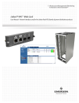
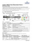
Infrastructure Management & Monitoring
For Business-Critical Continuity™
Liebert® RDU-S™ Rack Management Device
User Manual
TABLE OF CONTENTS
1.0
INTRODUCTION . . . . . . . . . . . . . . . . . . . . . . . . . . . . . . . . . . . . . . . . . . . . . . . . . . . . . . .1
1.1
1.2
Description . . . . . . . . . . . . . . . . . . . . . . . . . . . . . . . . . . . . . . . . . . . . . . . . . . . . . . . . . . . . . . 1
Ports and Indicators . . . . . . . . . . . . . . . . . . . . . . . . . . . . . . . . . . . . . . . . . . . . . . . . . . . . . . . 2
1.3
1.2.1
Ports . . . . . . . . . . . . . . . . . . . . . . . . . . . . . . . . . . . . . . . . . . . . . . . . . . . . . . . . . . . . . . . . . . . . 2
1.2.2
Status Indicators . . . . . . . . . . . . . . . . . . . . . . . . . . . . . . . . . . . . . . . . . . . . . . . . . . . . . . . . . . 2
Technical Specifications . . . . . . . . . . . . . . . . . . . . . . . . . . . . . . . . . . . . . . . . . . . . . . . . . . . . 3
1.3.1
Input Specifications . . . . . . . . . . . . . . . . . . . . . . . . . . . . . . . . . . . . . . . . . . . . . . . . . . . . . . . . 3
1.3.2
Output Specifications. . . . . . . . . . . . . . . . . . . . . . . . . . . . . . . . . . . . . . . . . . . . . . . . . . . . . . . 3
1.3.3
Ambient Specifications . . . . . . . . . . . . . . . . . . . . . . . . . . . . . . . . . . . . . . . . . . . . . . . . . . . . . 3
1.3.4
Mechanical Specifications . . . . . . . . . . . . . . . . . . . . . . . . . . . . . . . . . . . . . . . . . . . . . . . . . . . 3
1.4
Options . . . . . . . . . . . . . . . . . . . . . . . . . . . . . . . . . . . . . . . . . . . . . . . . . . . . . . . . . . . . . . . . . 4
2.0
INSTALLATION . . . . . . . . . . . . . . . . . . . . . . . . . . . . . . . . . . . . . . . . . . . . . . . . . . . . . . . .5
2.1
2.2
2.3
2.4
2.5
Installation Considerations . . . . . . . . . . . . . . . . . . . . . . . . . . . . . . . . . . . . . . . . . . . . . . . . .
Choosing a Mounting Method . . . . . . . . . . . . . . . . . . . . . . . . . . . . . . . . . . . . . . . . . . . . . . .
Horizontal Rack Mounting. . . . . . . . . . . . . . . . . . . . . . . . . . . . . . . . . . . . . . . . . . . . . . . . . .
Vertical Rack Mounting . . . . . . . . . . . . . . . . . . . . . . . . . . . . . . . . . . . . . . . . . . . . . . . . . . . .
Wall Mounting . . . . . . . . . . . . . . . . . . . . . . . . . . . . . . . . . . . . . . . . . . . . . . . . . . . . . . . . . . .
3.0
CONNECTING SENSORS AND OTHER DEVICES . . . . . . . . . . . . . . . . . . . . . . . . . . . . . . . .7
3.1
3.2
3.3
3.4
3.5
Connecting Sensors to RJ45 Sensor Ports . . . . . . . . . . . . . . . . . . . . . . . . . . . . . . . . . . . . .
Digital Input Ports DI1, DI2, DI3 . . . . . . . . . . . . . . . . . . . . . . . . . . . . . . . . . . . . . . . . . . . .
Liebert SN Sensor Ports. . . . . . . . . . . . . . . . . . . . . . . . . . . . . . . . . . . . . . . . . . . . . . . . . . . .
Connecting a Beacon to the Relay Output Ports . . . . . . . . . . . . . . . . . . . . . . . . . . . . . . . .
Connecting a Stationary or Tilt and Pan Camera to a USB Port . . . . . . . . . . . . . . . . . . .
4.0
PARAMETER SETTING . . . . . . . . . . . . . . . . . . . . . . . . . . . . . . . . . . . . . . . . . . . . . . . . .10
4.1
Setting the IP Address . . . . . . . . . . . . . . . . . . . . . . . . . . . . . . . . . . . . . . . . . . . . . . . . . . . . 10
5.0
WEB INTERFACE - OVERVIEW . . . . . . . . . . . . . . . . . . . . . . . . . . . . . . . . . . . . . . . . . . . 12
5.1
5.2
Log In . . . . . . . . . . . . . . . . . . . . . . . . . . . . . . . . . . . . . . . . . . . . . . . . . . . . . . . . . . . . . . . . . 12
Log Out . . . . . . . . . . . . . . . . . . . . . . . . . . . . . . . . . . . . . . . . . . . . . . . . . . . . . . . . . . . . . . . . 12
6.0
MONITOR TAB . . . . . . . . . . . . . . . . . . . . . . . . . . . . . . . . . . . . . . . . . . . . . . . . . . . . . . . 13
6.1
6.2
Overview - Monitoring Data . . . . . . . . . . . . . . . . . . . . . . . . . . . . . . . . . . . . . . . . . . . . . . . 14
Environmental Monitoring - Connected Devices . . . . . . . . . . . . . . . . . . . . . . . . . . . . . . . 15
6.3
5
5
5
6
6
7
7
8
8
9
6.2.1
Configure Alarm Setpoints - Temperature and Humidity Sensors. . . . . . . . . . . . . . . . . . 15
6.2.2
Input Contacts . . . . . . . . . . . . . . . . . . . . . . . . . . . . . . . . . . . . . . . . . . . . . . . . . . . . . . . . . . . 16
6.2.3
Output Relays . . . . . . . . . . . . . . . . . . . . . . . . . . . . . . . . . . . . . . . . . . . . . . . . . . . . . . . . . . . 17
6.2.4
Events List Area . . . . . . . . . . . . . . . . . . . . . . . . . . . . . . . . . . . . . . . . . . . . . . . . . . . . . . . . . 17
Camera Monitoring . . . . . . . . . . . . . . . . . . . . . . . . . . . . . . . . . . . . . . . . . . . . . . . . . . . . . . 18
6.3.1
Camera Control Buttons . . . . . . . . . . . . . . . . . . . . . . . . . . . . . . . . . . . . . . . . . . . . . . . . . . . 19
i
7.0
CONTROL TAB . . . . . . . . . . . . . . . . . . . . . . . . . . . . . . . . . . . . . . . . . . . . . . . . . . . . . . 21
7.1
7.2
7.3
7.4
Reboot . . . . . . . . . . . . . . . . . . . . . . . . . . . . . . . . . . . . . . . . . . . . . . . . . . . . . . . . . . . . . . . . .
Digital Output Control . . . . . . . . . . . . . . . . . . . . . . . . . . . . . . . . . . . . . . . . . . . . . . . . . . . .
Firmware Upgrade . . . . . . . . . . . . . . . . . . . . . . . . . . . . . . . . . . . . . . . . . . . . . . . . . . . . . . .
Configuration File . . . . . . . . . . . . . . . . . . . . . . . . . . . . . . . . . . . . . . . . . . . . . . . . . . . . . . .
21
22
23
23
7.4.1
Download the Configuration File in the Liebert RDU-S™ . . . . . . . . . . . . . . . . . . . . . . . . . 23
7.4.2
Upload the Configuration File to a Liebert® RDU-S™ . . . . . . . . . . . . . . . . . . . . . . . . . . . . 24
7.5
Restore Factory Defaults . . . . . . . . . . . . . . . . . . . . . . . . . . . . . . . . . . . . . . . . . . . . . . . . . . 24
8.0
CONFIGURE TAB . . . . . . . . . . . . . . . . . . . . . . . . . . . . . . . . . . . . . . . . . . . . . . . . . . . . . 25
8.1
8.2
Network. . . . . . . . . . . . . . . . . . . . . . . . . . . . . . . . . . . . . . . . . . . . . . . . . . . . . . . . . . . . . . . . 26
E-mail . . . . . . . . . . . . . . . . . . . . . . . . . . . . . . . . . . . . . . . . . . . . . . . . . . . . . . . . . . . . . . . . . 26
8.3
8.4
8.5
8.6
8.2.1
SMTP Server. . . . . . . . . . . . . . . . . . . . . . . . . . . . . . . . . . . . . . . . . . . . . . . . . . . . . . . . . . . . . 27
8.2.2
Recipients . . . . . . . . . . . . . . . . . . . . . . . . . . . . . . . . . . . . . . . . . . . . . . . . . . . . . . . . . . . . . . . 28
8.2.3
Test . . . . . . . . . . . . . . . . . . . . . . . . . . . . . . . . . . . . . . . . . . . . . . . . . . . . . . . . . . . . . . . . . . . . 28
SNMP . . . . . . . . . . . . . . . . . . . . . . . . . . . . . . . . . . . . . . . . . . . . . . . . . . . . . . . . . . . . . . . . .
Time. . . . . . . . . . . . . . . . . . . . . . . . . . . . . . . . . . . . . . . . . . . . . . . . . . . . . . . . . . . . . . . . . . .
Users . . . . . . . . . . . . . . . . . . . . . . . . . . . . . . . . . . . . . . . . . . . . . . . . . . . . . . . . . . . . . . . . . .
Sensors . . . . . . . . . . . . . . . . . . . . . . . . . . . . . . . . . . . . . . . . . . . . . . . . . . . . . . . . . . . . . . . .
29
30
31
32
8.6.1
DI Sensor Configure . . . . . . . . . . . . . . . . . . . . . . . . . . . . . . . . . . . . . . . . . . . . . . . . . . . . . . . 33
8.6.2
SN DI Sensor Configure . . . . . . . . . . . . . . . . . . . . . . . . . . . . . . . . . . . . . . . . . . . . . . . . . . . . 34
8.6.3
TH Sensor Configure . . . . . . . . . . . . . . . . . . . . . . . . . . . . . . . . . . . . . . . . . . . . . . . . . . . . . . 35
8.7
8.8
Auto Logout. . . . . . . . . . . . . . . . . . . . . . . . . . . . . . . . . . . . . . . . . . . . . . . . . . . . . . . . . . . . . 36
Change Password . . . . . . . . . . . . . . . . . . . . . . . . . . . . . . . . . . . . . . . . . . . . . . . . . . . . . . . . 37
9.0
EVENTS TAB. . . . . . . . . . . . . . . . . . . . . . . . . . . . . . . . . . . . . . . . . . . . . . . . . . . . . . . . 38
9.1
9.2
9.3
Digital Input Actions . . . . . . . . . . . . . . . . . . . . . . . . . . . . . . . . . . . . . . . . . . . . . . . . . . . . . 39
Temp & Hum Actions . . . . . . . . . . . . . . . . . . . . . . . . . . . . . . . . . . . . . . . . . . . . . . . . . . . . . 40
Event History . . . . . . . . . . . . . . . . . . . . . . . . . . . . . . . . . . . . . . . . . . . . . . . . . . . . . . . . . . . 41
9.3.1
Event History - Viewing Records. . . . . . . . . . . . . . . . . . . . . . . . . . . . . . . . . . . . . . . . . . . . . 41
9.3.2
Event History - Exporting Records . . . . . . . . . . . . . . . . . . . . . . . . . . . . . . . . . . . . . . . . . . . 42
9.4
Clear Event History . . . . . . . . . . . . . . . . . . . . . . . . . . . . . . . . . . . . . . . . . . . . . . . . . . . . . . 42
10.0
HISTORY TAB . . . . . . . . . . . . . . . . . . . . . . . . . . . . . . . . . . . . . . . . . . . . . . . . . . . . . . . 43
10.1
10.2
Chart . . . . . . . . . . . . . . . . . . . . . . . . . . . . . . . . . . . . . . . . . . . . . . . . . . . . . . . . . . . . . . . . . . 44
Table View of Historical Data . . . . . . . . . . . . . . . . . . . . . . . . . . . . . . . . . . . . . . . . . . . . . . 44
10.2.1 Viewing Records . . . . . . . . . . . . . . . . . . . . . . . . . . . . . . . . . . . . . . . . . . . . . . . . . . . . . . . . . . 44
10.2.2 Exporting Historical Data Records . . . . . . . . . . . . . . . . . . . . . . . . . . . . . . . . . . . . . . . . . . . 45
10.3
10.4
Interval . . . . . . . . . . . . . . . . . . . . . . . . . . . . . . . . . . . . . . . . . . . . . . . . . . . . . . . . . . . . . . . . 46
Clear History Data . . . . . . . . . . . . . . . . . . . . . . . . . . . . . . . . . . . . . . . . . . . . . . . . . . . . . . . 46
11.0
SYSTEM INFORMATION TAB . . . . . . . . . . . . . . . . . . . . . . . . . . . . . . . . . . . . . . . . . . . . . 47
ii
FIGURES
Figure 1
Figure 2
Figure 3
Figure 4
Figure 5
Figure 6
Figure 7
Figure 8
Figure 9
Liebert RDU-S . . . . . . . . . . . . . . . . . . . . . . . . . . . . . . . . . . . . . . . . . . . . . . . . . . . . . . . . . . . . . . . 1
Ports and indicators on front of unit . . . . . . . . . . . . . . . . . . . . . . . . . . . . . . . . . . . . . . . . . . . . . 2
Recommended digital sensors . . . . . . . . . . . . . . . . . . . . . . . . . . . . . . . . . . . . . . . . . . . . . . . . . . . 7
Liebert SN ports . . . . . . . . . . . . . . . . . . . . . . . . . . . . . . . . . . . . . . . . . . . . . . . . . . . . . . . . . . . . . . 7
Position of relay output ports . . . . . . . . . . . . . . . . . . . . . . . . . . . . . . . . . . . . . . . . . . . . . . . . . . . 8
Beacon wiring diagram . . . . . . . . . . . . . . . . . . . . . . . . . . . . . . . . . . . . . . . . . . . . . . . . . . . . . . . . 9
Position of USB ports, cameras . . . . . . . . . . . . . . . . . . . . . . . . . . . . . . . . . . . . . . . . . . . . . . . . . . 9
Input Contacts window . . . . . . . . . . . . . . . . . . . . . . . . . . . . . . . . . . . . . . . . . . . . . . . . . . . . . . . 16
Output Relays window . . . . . . . . . . . . . . . . . . . . . . . . . . . . . . . . . . . . . . . . . . . . . . . . . . . . . . . . 17
TABLES
Table 1
Table 2
Table 3
Table 4
Table 5
Table 6
Table 7
Table 8
Port descriptions. . . . . . . . . . . . . . . . . . . . . . . . . . . . . . . . . . . . . . . . . . . . . . . . . . . . . . . . . . . . . .
Indicator descriptions. . . . . . . . . . . . . . . . . . . . . . . . . . . . . . . . . . . . . . . . . . . . . . . . . . . . . . . . . .
Input specifications . . . . . . . . . . . . . . . . . . . . . . . . . . . . . . . . . . . . . . . . . . . . . . . . . . . . . . . . . . .
Output specifications . . . . . . . . . . . . . . . . . . . . . . . . . . . . . . . . . . . . . . . . . . . . . . . . . . . . . . . . . .
Ambient specifications . . . . . . . . . . . . . . . . . . . . . . . . . . . . . . . . . . . . . . . . . . . . . . . . . . . . . . . . .
Mechanical specifications. . . . . . . . . . . . . . . . . . . . . . . . . . . . . . . . . . . . . . . . . . . . . . . . . . . . . . .
Options . . . . . . . . . . . . . . . . . . . . . . . . . . . . . . . . . . . . . . . . . . . . . . . . . . . . . . . . . . . . . . . . . . . . .
Mounting methods . . . . . . . . . . . . . . . . . . . . . . . . . . . . . . . . . . . . . . . . . . . . . . . . . . . . . . . . . . . .
iii
2
2
3
3
3
3
4
5
iv
Introduction
1.0
INTRODUCTION
This section provides an overview of the Liebert® RDU-S™, including the ports, indicators, technical
specifications and options.
1.1
Description
The Liebert RDU-S is a compact rack processing unit designed to monitor the environment in
electronic equipment racks and rooms through various types of sensors and cameras. The unit can
accommodate multiple sensors, such as smoke and motion detectors and Liebert SN™ temperature
and humidity sensors. It can also be used for remote notification such as activating a beacon light to
report problems.
The compact design makes it suitable for installation in a rack, where it takes up little space, or it
may be mounted on a wall for access without opening the equipment rack.
The unit is shown in Figure 1.
Figure 1
Liebert RDU-S
1
Introduction
1.2
Ports and Indicators
Figure 2 shows the front panel of the Liebert RDU-S™ with the location of ports (Table 1) and status
indicators (Table 2).
Figure 2
Ports and indicators on front of unit
FRONT OF UNIT
Relay
output
ports
Power
input
Digital
input
ports
DI1-3
Ethernet
port
USB ports
12VDC
output
RJ45 SENSOR PORTS
RJ45 sensor
ports
Micro SD
card slot
DO1/DO2
outputs
Status
indicators
Power
Liebert SN ports
Alarm
DO1
Power
Alarm
Not Used
DO2
Run
Not Used
Not Used
STATUS
INDICATORS
Run
1.2.1
Ports
The ports and their functions are listed in Table 1.
Table 1
Port descriptions
Port
#
Label
Function
Power Input
1 100-240V~Input Input power to the unit: 100-200VAC, 50 and 60Hz
Relay Output Ports
2 DO1, DO2
Connect to output relays 1 and 2—e.g., beacon light
12VDC Output
2 12V GND
Power to external sensor (12VDC power)—e.g., beacon light
Micro SD Card Slot
1 Micro SD
Expand storage capacity with 8G Micro SD card
USB Ports
2 USB1, USB2
Ethernet Port, RJ45 1 ETH
Connect to a USB camera
Connect to a 10/100 Ethernet port for Web access & SNMP connectivity
RJ45 Sensor Ports*:
Digital Input Ports
3 DI1, DI2, DI3
Connect digital sensors (one sensor per port)—On/Off, dry contact
sensors, such as smoke detectors and motion detectors
Liebert SN Ports
2
Connect Liebert SN sensors to monitor temperature, humidity, dry
contact, door sensor and leak detection
* See Section 3.1 for details on connecting sensors to RJ45 sensor ports (excluding Ethernet port).
1.2.2
Status Indicators
Refer to Table 2 for details on the unit’s status indicators: relay outputs, power, alarm and run.
Table 2
Indicator
Indicator descriptions
Status of:
Color
Status - Indicator On / Flashing
Status - Indicator Off
DO1, DO2 Relay outputs
Yellow On
Relay DO1 or DO2 is closed. Off Relay DO1 or DO2 is open.
POWER
Input power
Green On
Input power is present.
Off Input power is not present.
ALARM
Alarms
Red
On-Solid
Unit has a critical alarm./
Unit is powering up.
Off No alarms detected.
Flashing
Unit has a warning alarm.
Unit operation Green Flashing
Unit is operating normally.
RUN
2
Off Unit is not running.
Introduction
1.3
Technical Specifications
1.3.1
Input Specifications
The input specifications of the processing unit are listed in Table 3.
Table 3
1.3.2
Input specifications
Input
parameters
Corresponding
port
Measurement
accuracy
Liebert SN
sensor input
Liebert SN sensor port
Determined by
sensor used
Digital
signal input
DI1, DI2, DI3 ports
Description
Measures temperature, humidity, dry contact,
cabinet door status and leak detection.
Measures the digital signal from connected
smoke sensors and motion sensors.
—
Output Specifications
The output specifications of the processing unit are listed in Table 4.
Table 4
Output specifications
Output parameters
Relay
output
Sensor
power
output
Specification
Description
Output contact
Relay normally open contact output
Contact capacity
5A/24VDC
Output relays to control external device, such
as a beacon light.
12VDC output
11.5VDC to 12.5VDC, maximum
output current: 0.8A
USB port output
1.3.3
The output current is the total current the
sensor power can provide. The total power
consumption of 12VDC power does not
exceed 10W.
Maximum output current: 500mA
—
Ambient Specifications
The ambient specifications of the processing unit are listed in Table 5.
Table 5
Ambient specifications
Item
Application location
Indoor
Working temperature, °F (°C)*
32 to 113 (0 to 45)
Relative humidity
5% - 95%RH (non-condensing)
Storage temperature, °F (°C)
-40 to 158 (-40 to 70)
Cooling
Natural cooling
Liebert®
* Applies to the
prevent damage.
1.3.4
Requirement
RDU-S™,
not any devices connected to it. Check the temperature range for connected devices to
Mechanical Specifications
The mechanical specifications of the processing unit are listed in Table 6.
Table 6
Mechanical specifications
Dimensions - W x D x H, in. (mm)
17.3 x 2.2 x 1.7 (440 × 55 × 44.2)
Weight, lb. (kg)
3.3 (1.5)
3
Introduction
1.4
Options
The options for the Liebert® RDU-S™ are listed in Table 7. Refer to 3.0 - Connecting Sensors and
Other Devices for connection instructions.
Table 7
Options
Type
Digital
sensors
Liebert
SN Sensor
Beacon
Cameras
Description
Part No.
Smoke sensor
AD-S
Motion sensor
AD-IM
Integrated cable with single temperature sensor
SN-Z01
Integrated cable with three temperature sensors
SN-Z02
Integrated cable with three temperature sensors
and one humidity sensor
SN-Z03
Modular with single temperature sensor
SN-T
Modular with single temperature sensor and
single humidity sensor
SN-TH
Port
Digital RJ45 ports
(DI1, DI2, DI3)
Liebert SN sensor ports
Modular with three dry contact inputs
SN-3C
Modular with two door contact inputs
SN-2D
Two door switches with mounting brackets
for DCM rack
AD-2D-DCM
SN-2D Sensor
LED Strobe Light
AD-RB
Relay output ports (DO1, DO2)
and 12VDC output
Stationary USB Camera
AD-SUSBC
USB ports
(USB1, USB2)
Tilt and Pan USB Camera
AD-TPUSBC
USB ports
(USB1, USB2)
Camera Memory
AD-MICROSD8
Micro SD Card Slot
4
Installation
2.0
INSTALLATION
This section provides details for the various options of mounting the Liebert® RDU-S™ securely in a
rack or on a wall.
WARNING
!
Ensure that the Liebert RDU-S is Off and that all local and remote input power sources have
been disconnected before beginning to install the unit. Never open, alter or move the unit
while input power is present.
NOTE
All external circuits must be safety extra-low voltage (SELV) circuits. The insulation and
isolation must be enhanced between the SELV circuits and the power grid.
2.1
Installation Considerations
Mount the Liebert RDU-S securely before connecting equipment, typically in a 19" rack or mounted
on a wall.
• The Liebert RDU-S must be installed near a power outlet or socket within easy reach using the
supplied power cord.
• The unit must be connected to the power outlet or socket with protective earthing terminal.
• The unit must be securely installed in a rack or on a wall BEFORE using or connecting any
equipment.
2.2
Choosing a Mounting Method
Select the mounting option that best fits your needs:
Table 8
Mounting methods
Mounting option
2.3
Tools needed
For details, see:
• Horizontal mounting in a rack
Factory-supplied brackets and screws
2.3 - Horizontal Rack Mounting
• Vertical mounting in a rack
Optional round hanger (available separately)
2.4 - Vertical Rack Mounting
• Mounting on a wall
Factory-supplied brackets and screws
2.5 - Wall Mounting
Horizontal Rack Mounting
For horizontal mounting in a rack, use the factory-supplied brackets and screws (M3 and M6):
1. Place the shorter side of a bracket flush with the front panel and the longer side against one side
of the unit, shown below left.
2. Align the rear bracket hole with a mounting hole on the unit, shown below left, and use an M3
screw to fasten the bracket to the side of the unit.
Mounting hole
for rack mounting
Unit with both side
brackets attached
FRONT OF UNIT
Bracket flush with front of unit
3. Repeat Steps 1 and 2 for the bracket on the other side. The Liebert RDU-S with both brackets
attached is shown above right.
4. Use field-supplied M6 screws to fasten both brackets of the Liebert RDU-S onto the rack’s front or
rear rails.
5
Installation
2.4
Vertical Rack Mounting
Mounting holes
A-H for round
hanger
For vertical mounting in a rack, use the optional round hanger
(available separately) and a factory-supplied M3 screw:
1. Decide which mounting hole to use—there are four vertical
mounting holes on top (A-D, shown at right) and four on the
rear (E-H).
2. Fasten the round hanger onto the top or back of the unit
with an M3 screw. The example at far right shows the
hanger fastened to the rear of the unit.
3. Hang the unit in the rack by inserting the round hanger
through a mounting slot on a vertical rail.
2.5
A
B
E
F
Mounting
Hole
Round
Hanger
C
D
G
H
TOP
OF
UNIT
REAR
OF
UNIT
Wall Mounting
To mount the unit on a wall, use the factory-supplied brackets and screws (M3):
1. Place the shorter side of a bracket flush with the rear panel and the other against one side of the
unit.
2. Align the front bracket hole with a mounting hole on the unit, shown below, and use an M3 screw
to fasten the bracket to the side of the unit.
Bracket flush
with rear of unit
18" (458mm)
1-1/4"
(31mm)
Both side brackets attached
FRONT OF UNIT
Mounting hole for wall mounting
3. Repeat Steps 1 and 2 for the bracket on the other side.
4. Drill four holes in the wall corresponding to the bracket hole dimensions shown above, then insert
a wall anchor into each hole.
5. Align the bracket holes with the drilled holes and use screws to attach the unit to the wall.
6
Connecting Sensors and Other Devices
3.0
CONNECTING SENSORS AND OTHER DEVICES
NOTE
The power and external signals that are connected to the Liebert® RDU-S™ must be SELV
circuits. The isolation and insulation must be enhanced between them and the power grid.
This section provides instructions for connecting factory-supplied devices to the Liebert RDU-S for
monitoring and management: smoke detector, motion detector, Liebert SN temperature and humidity
sensor, beacon light and USB cameras.
NOTE
This section provides guidelines for connecting devices to the Liebert RDU-S. Refer to the
corresponding instructions for complete details on installation and specifications.
3.1
Connecting Sensors to RJ45 Sensor Ports
The Liebert RDU-S has two types of sensor ports on the front of the unit: three digital sensor ports
and two Liebert SN sensor ports, Follow these guidelines to connect sensors to these ports and refer to
the sensor installation instructions.
3.2
Digital Input Ports DI1, DI2, DI3
The three digital input ports DI1, DI2 and DI3, shown at right, may be used to connect digital smoke
and motion detectors. You may use any standard straight-through RJ45 Ethernet cable.
The recommended sensors are shown in Figure 3.
Figure 3
Recommended digital sensors
AD-IM Motion Sensor
AD-S Smoke Sensor
To connect the factory-supplied smoke detector or motion detector:
• Insert either end of an RJ45 connector on an RJ45-RJ45 cable into any of the three digital ports—
labeled DI1, DI2 and DI3—on the Liebert RDU-S, shown at right.
• Connect the other end of the cable to the RJ45 port on the smoke detector or motion detector.
Figure 4
Liebert SN ports
Connect one end of an
RJ45 cable to a Liebert
SN port
Digital
input
ports
DI1-3
Connect the other end of the
RJ45 cable to the sensor
Liebert SN ports
7
Connecting Sensors and Other Devices
3.3
Liebert SN Sensor Ports
The two ports labeled with a Liebert SN icon , shown above, are designed for use with Liebert SN
sensors. Each sensor is shipped with a cable to connect to one of the Liebert SN ports on the
Liebert RDU-S™. You may use this cable or another standard straight-through cable.
The two Liebert SN ports can support:
•
•
•
•
•
Temperature sensors—10
Humidity sensors—10
SN-3C sensors—3 (9 digital inputs)
SN-2D sensors—3 (6 door inputs)
Leak sensor—1
The maximum combined cable length from the Liebert® RDU-S™ to the last sensor is 65.6 feet (20m).
To connect the sensor:
• Insert either end of an RJ45 connector on the factory-supplied RJ45-RJ45 cable (or user-supplied
cable) into the Liebert SN port on the Liebert RDU-S, identified by the icon shown below.
Icon
Description
Liebert SN
ports
Purpose
Use these ports ONLY
for Liebert SN sensors.
• Connect the other end of the cable to the sensor.
3.4
Connecting a Beacon to the Relay Output Ports
The relay output ports shown in Figure 5 may be used to connect the beacon light shipped with the
Liebert RDU-S. Follow these guidelines and refer to the beacon installation instructions.
Figure 5
Position of relay output ports
FRONT OF UNIT
Relay output ports
To connect the beacon light:
1. Connect the required cables with either of the relay output ports labeled DO1 and DO2. The relay
of the processing unit is normally open passive dry contact.
2. Properly arrange the wiring according to the site conditions.
Refer to Figure 6.
8
Connecting Sensors and Other Devices
Figure 6
Beacon wiring diagram
DO1
12V GND
Jumper
DO2
12V GND
Red
Wire
Black
Wire
Beacon
NOTE
Pay attention to the port labels before connection to avoid possibly damaging the device by
making the wrong connection.
3.5
Connecting a Stationary or Tilt and Pan Camera to a USB Port
The USB ports shown in Figure 5 may be used to connect either or both optional cameras. Follow
these guidelines and refer to the installation instructions for each camera.
Figure 7
Position of USB ports, cameras
FRONT OF UNIT
USB
Tilt and Pan
Camera
USB ports
USB
Stationary
Camera
To connect a camera, connect the attached USB cable to one of the USB ports labeled USB1 and
USB2.
NOTE
The video camera, as shipped, will relay images and video to a monitoring screen. Recording
images or video requires a micro SD card, which is available from the factory, part number
AD-MICROSD8.
9
Parameter Setting
4.0
PARAMETER SETTING
A Web interface allows you to view monitoring data, configure the unit and connected devices and
manage alarms and other data. This interface is accessible by connecting an Ethernet cable from the
unit to a computer on a network.
The Liebert® RDU-S™ has a default IP address (192.168.0.10). This section describes how to change
the unit’s IP address.
4.1
Setting the IP Address
Follow these instructions to set the IP address of the Liebert RDU-S. This step is required for
communication with the Liebert RDU-S using the Web interface.
1. Connect a laptop and set its IP address:
• Insert a standard Ethernet cable (not included) into the
Ethernet port on the front panel of the Liebert RDU-S,
shown at right.
• Insert the other end of the cable into a laptop’s Ethernet
port.
• If needed, configure the laptop’s IP settings to
communicate on a 192.168.0.X network, for example:
Ethernet port
IP address
192.168.0.9
Subnet mask
255.255.255.0
Default gateway 192.168.0.1
2. Open a browser and go to the login page:
• Open a Web browser such as Microsoft Windows® Internet
Explorer.
• Enter the IP address of the Liebert RDU-S in the address
bar—the default is http://192.168.0.10. The login window
appears, shown at right.
3. Log in to the Web interface:
• Select a user name from the drop-down list and enter a
password (both case-sensitive), then click the Login button:
• User Name (default is admin)
• Password (default is Liebert)
NOTE
For security, change the default password (see 8.8 - Change Password).
4. Click the Configure tab, then click Network at left.
Configure
DHCP
Static
Network
10
Parameter Setting
5. Determine which method to use for IP address assignment: DHCP (automatic) or Static (fixed
address).
• For DHCP, click the Obtain IP address automatically button.
• To assign a Static IP address, click Use the following IP address, then enter the
appropriate IP address, subnet mask and gateway address, for example:
IP address
192.168.0.10
Subnet mask
255.255.255.0
Default gateway 192.168.0.1
6. Click Apply to save any changes.
7. A confirmation window indicates the unit must be
rebooted for the change to take effect. Click OK, and the
unit will reboot.
8. If needed, reset the laptop’s IP settings (as in Step 1).
9. Connect the Liebert® RDU-S™ to your network.
11
Web Interface - Overview
5.0
WEB INTERFACE - OVERVIEW
The Liebert® RDU-S™ has a Web interface for monitoring and managing connected devices. This
section offers details on logging in and using monitoring, configuration and control functions of the
Web interface.
NOTE
Java V1.6 or above is required for proper operation. Check to make sure you have the latest
Java update.
5.1
Log In
To log in to the Web interface:
1. Open a Web browser such as Internet Explorer.
2. In the browser address bar, enter the IP address assigned to the Liebert RDU-S, then press the
Enter key. The Login window appears, as shown below.
• The unit is shipped with a default IP address: 192.168.0.10.
• See 4.1 - Setting the IP Address for details on changing the IP address.
3. If desired, choose a language from the drop-down list—the default is English.
4. Select a user name from the User Name drop-down list and enter a password in the Password box.
• The default user name is admin (case-sensitive).
• The default password is Liebert (case-sensitive).
NOTE
Some browsers may not permit entering a password on the first attempt. If the password box
will not accept an entry, try these steps:
• Click the Reset button.
• Try to enter the password again.
5. Click the Login button to enter the Web interface.
The default opening view after login is the Monitor tab, as shown in 6.0 - Monitor Tab.
5.2
Log Out
To exit the Web interface:
Logout
• Click Logout, which appears next to the user name in the top left
corner of every window.
NOTE
Be sure to exit properly by clicking Logout to prevent unauthorized access to the Web interface.
12
Monitor Tab
6.0
MONITOR TAB
The Monitor tab provides access to the following functions:
Function
For details, see:
View status of connected devices
View list of recent alarms and other events
Configure alarm setpoints for temperature and humidity sensors
6.2 - Environmental Monitoring - Connected
Devices
Turn DO1 and DO2 ports On or Off
Access the camera interface
6.3 - Camera Monitoring
Monitor
tab
Monitor
options
13
Monitor Tab
6.1
Overview - Monitoring Data
The default opening view displays monitoring data for connected devices, as in the following example.
Monitor
tab
Tabs
Environmental
subtab
Subtabs
Monitoring
data
Connected
devices
(shown in
groups)
Events
To view monitoring data for connected devices:
• Click on the Monitor tab.
• Click on the Environmental subtab. The left pane shows a list of connected equipment, and the
right pane shows monitoring data. Each side is organized in groups. If a device in any group has
an active alarm:
• The group expands automatically in the right pane to display all devices in that group.
• An icon in the group heading indicates the level of severity (Critical or Warning).
• The number of devices in alarm appears in red text in parentheses.
• Click on a group name—e.g., Input Contacts—on either side to expand or collapse the group.
• Click on Collapse All / Expand All in the left pane to collapse or expand all groups.
Recent events appear at bottom right with details of each event such as type of alarm, time of
occurrence, sensor name and severity. These include the following types of events:
• Critical (Red) - temperature or humidity beyond the high or low Critical setpoint or a Digital
Input contact is not in its normal state (open if normally closed or closed if normally open)
• Warning (Yellow) - temperature or humidity beyond the high or low Warning setpoint
• Normal (Green) - device has returned to normal after a critical or warning alarm
• Loss of Comms - no communication with the device
14
Monitor Tab
6.2
Environmental Monitoring - Connected Devices
The right pane of the Environmental view displays the status of each connected device and a list of
the most recent alarms and other events.
This area also offers access to view and adjust parameters for connected devices—temperature and
humidity sensors, input contacts and output relay contacts.
6.2.1
Configure Alarm Setpoints - Temperature and Humidity Sensors
To view or change the name or alarm setpoints of a temperature or humidity sensor:
• Click on the Monitor tab.
• Click on the Environmental subtab.
In the right pane, you may change the name and the alarm setpoints to trigger Warning and
Critical alarms of a temperature or humidity sensor.
View Sensor Status
• If needed, click on the sensor group name in the right pane—Temperature Sensors or
Humidity Sensors—to expand the view for connected sensors. The view expands automatically
when an alarm is detected for any sensor in the group.
• Each sensor has a graph with the current value displayed above the graph in color to indicate
whether the value is in the Normal range (green), Warning (yellow) or Critical (red).
• Hold the mouse over a graph to reveal a pop-up list of configured locations (see 8.6.3 - TH Sensor
Configure).
Temperature
sensors
Normal (Green)
Warning (Yellow)
Critical (Red)
Warning (Yellow)
Critical (Red)
Critical (Red)
Humidity
sensors
15
Pop-up
list of
locations
Monitor Tab
Edit Temperature or Humidity Alarm Setpoints
• Double-click on a sensor graph to edit the sensor name or alarm setpoints.
The selected sensor has a gray background, as shown below. The graph ranges are displayed in
color: Low and High Critical (red), Low and High Warning (yellow), Normal (green). Along the
bottom of the gray area are the sensor names and the Apply and Cancel buttons.
DETAIL VIEW
Selected
sensors
Sensor type
Sensor address
Sensor name
Change setpoints
• The sensor name appears in a text box at the bottom of the gray area—SN Temp1 and SN Hum1
in the examples above. To change the name, click in the text box and enter a new name, which
may consist of up to 10 characters.
• The numbers below Temp and RelHum are the Liebert SN sensor addresses, which can be used
to identify a sensor. This address may be found on a label on the Liebert SN sensor (see the user
manual for your Liebert SN sensor). The sensor address cannot be changed.
• The Warning, Critical and Normal graph ranges are separated by black vertical bars that
represent the alarm setpoints. To change a setpoint:
• Hold the mouse over a black separator until the cursor changes shape.
• Click-and-drag the bar to adjust the threshold. The value is displayed as you drag the mouse.
• Release the mouse button at the desired value.
• Click Apply to save any changes (or click Cancel to close the editing window without saving).
6.2.2
Input Contacts
Click the Input Contacts node in the Monitor structure tree. See Figure 8 for a typical view.
You can view the working status of the connected digital sensors. The black font under icons signifies
normal status and red font signifies alarm. For example, as shown in Figure 8, the motion sensor is
of black font, which means the sensor is normal and did not detect any alarm. While the door sensor is
of red font, it means an alarm has been detected.
Input contacts must be enabled before they will show up on the monitor tab. To enable the input
contact, select sensors under the configuration option. See 8.6 - Sensors.
Figure 8
Input Contacts window
NOTE
If an Input Contact is displayed on the monitor tab, double-clicking on an input contact icon
opens the sensor configuration window.
16
Monitor Tab
6.2.3
Output Relays
Click the Output Relays node in the Monitor structure tree. See Figure 9 for a typical view.
This window displays the status of the devices connected to relay port. For example, the DO1
(indicator alarm) turning red indicates that the relay is closed.
Figure 9
Output Relays window
• Click on the Monitor tab.
• If needed, click on the Environmental subtab in the left pane and expand the Output Relays
section in the right pane.
• The DO ports may be turned On or Off using a shortcut in the Monitor tab as follows (or from the
Control tab as described in 3.4 - Connecting a Beacon to the Relay Output Ports):
• Double-click a DO1 or DO2 icon to open a pop-up menu.
• Choose On or Off from the drop-down list.
• Click the Confirm button to save any changes (or click Cancel to close without saving)..
6.2.4
Events List Area
The system will display the latest 20 events here including Critical, High Warning, Loss of Comms
and Normal events.
The Event History button is a shortcut to the Events tab; see 9.3 - Event History.
17
Monitor Tab
6.3
Camera Monitoring
Up to two cameras may be connected to the Liebert® RDU-S™ (see 3.5 - Connecting a Stationary or
Tilt and Pan Camera to a USB Port).
To access the camera interface:
• Click on the Monitor tab at the top of the window, then click on the Camera subtab.
• In the left pane, click to expand USB Cameras, then choose a camera view:
• Click All Camera to display both cameras side-by-side, as shown below.
• Click Camera 1 or Camera 2 to display only one camera image at a time.
Monitor
All Camera
Camera 2
18
Monitor Tab
6.3.1
Camera Control Buttons
Control buttons appear below each camera image, as shown below.
• Click on the arrows to change the direction of the tilt and pan camera up, down, left and right.
• Click on the plus (+) or minus (-) buttons to increase or decrease contrast and brightness.
Arrows - Control
Camera Direction
Contrast &
Brightness
Record/Replay
Video
Capture/Preview
Still Images
NOTE
An SD card is required for the camera to record video or capture still images; the camera has
no memory without the card.
Taking Still Photos
• Click Capture to take a still photo in JPG format.
• Click Preview to view a list of captured images. The file names are listed as hypertext links,
along with the date and time created and file size, as shown below. In this window, you may:
• View a photo - click on a link to preview the image (close preview window to return to list).
• Remove a file - check one or more boxes at left, then click the Delete button.
• Save an image - right-click on the file name and select an option.
Delete
19
Monitor Tab
Recording Videos
• The default frame frequency is 20 frames/second. To change this, choose a number from the
Frames/sec drop-down list, then click Apply.
• Click Record to start a video recording in SM4 format. The button label changes to Stop.
• Click Stop to end the recording.
• Click Replay to view a list of videos, as shown below. The file names are listed as hypertext links,
along with the date and time created and file size, as shown below. In this window, you may:
• View a video - click on a link to replay the video (close replay window to return to list).
• Remove a file - check one or more boxes at left, then click the Delete button.
• Save an image - right-click on the file name and select an option.
Delete
NOTE
1. Do not pull out the SD card while recording.
2. Maximum recording times are:
• 2 minutes for an event alarm
• 15 minutes for manual recording
20
Control Tab
7.0
CONTROL TAB
The Control tab provides access to the following functions:
Function
For details, see:
Restart the Liebert® RDU-S™ after configuration changes
(e.g., upgrade firmware)
7.1 - Reboot
Turn DO1 and DO2 ports On or Off
7.2 - Digital Output Control
Update the unit’s firmware
7.3 - Firmware Upgrade
Install a new configuration file
7.4 - Configuration File
Reset configuration to factory defaults
7.5 - Restore Factory Defaults
Control
tab
Control
options
7.1
Reboot
Some configuration operations require rebooting the Liebert RDU-S—for example, after upgrading
the firmware. This process will restart the unit without loss of historical data or configuration
settings.
To restart the unit:
• Click on the Control tab at the top of the window.
• In the left pane, click Reboot.
• When ready, click the Reboot button at right. A message indicates the unit is restarting.
NOTE
Do not close or refresh your browser or open another browser window. Wait until the process is
completed before opening other applications or using the computer for other tasks.
Control
Reboot
21
Control Tab
7.2
Digital Output Control
This function allows you to turn power to the DO1 and DO2 ports On or Off. For connection details,
see 3.4 - Connecting a Beacon to the Relay Output Ports.
NOTE
These controls are also accessible from the Monitor tab (see 6.2.3 - Output Relays).
To change the On/Off status of digital output ports:
• Click on the Control tab at the top of the window.
• In the left pane, click Digital Output Control.
• The current status of the DO1 and DO2 output relay ports—On or Off—is shown at right. For
each port you wish to change:
• Click the arrow to display the drop-down list.
• Select On or Off.
• Click Apply to save any changes.
Control
Digital
Output
Control
22
Control Tab
7.3
Firmware Upgrade
Visit the Liebert® Web site at www.liebert.com to check for firmware updates. The firmware
download will include instructions for performing the upgrade.
7.4
Configuration File
The configuration file is has two functions:
• Download - Copies (makes a backup) the current RDU-S configuration to the system running the
Web browser.
• Upload - Browse to the downloaded configuration file to restore the configuration to the RDU-S.
The upload does not restore the network configuration.
7.4.1
Download the Configuration File in the Liebert RDU-S™
Downloading the configuration file from a Liebert RDU-S permits implementing the same settings at
multiple sites or on multiple units at the same site. The downloaded file also can be used to restore
the settings to a device. Once the file is downloaded, it can be uploaded to the additional devices or to
the original Liebert RDU-S.
•
•
•
•
Click on the Control tab at the top of the window.
In the left pane, click Configure File.
Click on the link.
Click the link Click Here to download Configuration in the center of the window to download
the file from the Liebert RDU-S.
• In the File Download window, click the Save button to save the configuration file where you can
find it by selecting a destination folder.
Control
Configure
File
23
Control Tab
7.4.2
Upload the Configuration File to a Liebert® RDU-S™
• When ready to complete the configuration update process, double-click on the file name of the
configuration file as described below.
• Specify the full path of the downloaded file in the Configure File box, or click the Browse button
to locate the file and click Open. The configuration file must be named configure.rdus.
• When ready to begin, click Upload. A message indicates the file upload is in progress.
NOTE
Do not close or refresh your browser or open another browser window. Wait until the process is
completed before opening other applications or using the computer for other tasks.
• After the process is completed successfully, restart the Liebert RDU-S (see 7.1 - Reboot).
7.5
Restore Factory Defaults
At any time, you may reset all configuration settings to the factory defaults. This includes all
user-defined settings for connected devices as well as the unit itself.
Restoring the factory defaults returns the IP address to 192.168.0.10.
To do this:
• Click on the Control tab at the top of the window.
• In the left pane, click Restore Factory Defaults. A message indicates the unit is restarting.
This process may take a few minutes.
NOTE
Do not close or refresh your browser or open another browser window. Wait until the process is
completed before opening other applications or using the computer for other tasks.
Control
Restore
Factory
Defaults
24
Configure Tab
8.0
CONFIGURE TAB
The Configure tab provides access to the following functions:
Function
For details, see:
View or change IP address, subnet mask and default gateway for Web interface
8.1 - Network
Configure unit to send e-mail notifications of alarms (up to 8 recipients)
8.2 - E-mail
Configure up to 20 computers to receive SNMP traps
8.3 - SNMP
Set date and time automatically or manually, including Daylight Saving Time
8.4 - Time
Add up to 8 users with passwords and full, partial or read-only access
8.5 - Users
Configure devices connected to the DI and Liebert SN ports
8.6 - Sensors
Specify automatic logout for users after a period of no activity
8.7 - Auto Logout
Change administrator’s password
8.8 - Change Password
Configure
tab
Configure
options
25
Configure Tab
8.1
Network
The Network settings include the IP address, subnet mask and default gateway of the Liebert®
RDU-S™. Emerson recommends keeping the default settings in most cases. Check with your network
administrator for recommended practices. The MAC address of the unit cannot be changed.
To view or change the network settings:
• Click the Configure tab at the top of the window.
• Click Network at left.
Configure
DHCP
Static
Network
• Determine which method to use for IP address assignment: DHCP (automatic) or Static (fixed
address). The factory-set IP address is 192.168.0.10.
• For DHCP, click the Obtain IP address automatically button.
• To assign a Static IP address, click Use the following IP address, then enter the
appropriate IP address, subnet mask and gateway address, for example:
IP address
192.168.0.10
Subnet mask
255.255.255.0
Default gateway 192.168.0.1
(factory default)
• Click Apply to save any changes.
• A confirmation window indicates the unit must be
rebooted for the change to take effect. Click OK, and the
unit will reboot.
8.2
E-mail
Use the E-Mail function to configure the Liebert RDU-S to send e-mail notifications of alarms to
specified recipients, including the outgoing mail server and e-mail addresses of intended recipients,
and to send test messages to verify the configuration.
To view or change the e-mail settings:
• Click on the Configure tab at the top of the window.
• In the left pane, click E-mail.
• Refer to the following sections to configure the unit for e-mail notifications.
26
Configure Tab
8.2.1
SMTP Server
The SMTP Server identifies the outgoing mail server that will be used to send e-mail notifications of
alarms to configured recipients.
• Click the SMTP Server subtab in the right pane.
• Enter the IP address of the outgoing mail server in the SMTP Server IP Address box.
• The SMTP Server Port is used to send the e-mail. Do not change the default port without
consulting your e-mail administrator.
• Check the Confirm Identity box to verify the SMTP Server IP Address entry. (Required if SMTP
server requires you to be logged in to send e-mail.)
• Enter your e-mail account user name in the E-mail Account text box.
• Enter the password for the e-mail account in the E-mail Password text box.
• Enter the sender’s e-mail address in the From Address text box. This address will appear on all
alarm notifications sent to configured recipients.
• Click Apply to save any changes.
• A confirmation window opens. Click OK to proceed (or click Cancel without saving).
Configure
E-mail
27
Configure Tab
8.2.2
Recipients
Up to eight e-mail addresses may be configured to receive notifications of events.
• Click the Recipients subtab in the right pane.
• Click the Add Recipient button to add an e-mail address.
• Enter a recipient’s e-mail address in the To Address text box. If needed, click Reset to clear
the entry and re-enter the e-mail address.
• Click Apply to save the address (Cancel to close this area without saving).
• To remove an entry from the Recipient Address list, select it and click the Delete button.
• Enable emails for all events. By selecting this option the Liebert® RDU-S™ will send an email for
all events. If the option is not selected, the event action must be created for events that an email
will be generated for.
Configure
Enable
e-mails
for all
events
E-mail
8.2.3
Test
Send a test message to verify the e-mail configuration.
•
•
•
•
•
•
Click the Test subtab in the right pane.
Enter an e-mail address in the From Address text box.
Choose an e-mail address from the Recipient Address list.
Enter a message in the Test Message box.
Click the Test button. A notification window will indicate success or failure.
Also check to make sure the recipient received the test message.
Configure
E-mail
28
Configure Tab
8.3
SNMP
Up to 20 computers may be configured to receive SNMP traps from the Liebert® RDU-S™.
• Click on the Configure tab at the top of the window.
• In the left pane, click SNMP.
• The Send Heart Beat box is enabled to send traps every 5 minutes by default. To change this:
• Place a check mark in the Send Heart Beat box to enable the feature (or remove the check
mark to disable it).
• Enter the number of minutes in the text box. Valid entries range from 1 to 1500.
• Click the Add button in the right pane to reveal the Add NMS area.
• Click to specify the SNMP version: SNMP V2c or SNMP V3.
NOTE
Use SNMP V2c for Liebert Nform.
• Enter the IP address of the NMS to be added in the NMS IP text box.
• The default Traps Port is 162 (recommended). Enter a different port if needed.
• The default Read Community is public. Enter a different string if needed.
• The default Write Community is private. Enter a different string if needed.
• When finished, click Apply to save the changes (or Cancel to close this area without saving).
• To remove an entry from the SNMP list, select it and click the Delete button.
• Enable Send Heart Beat. When this option is enabled, the Liebert RDU-S will send a heart beat
trap to all NMS IP addresses at specified intervals. Put a checkmark in the “Send Heart Beat,” set
the interval from 1 to 1500 minutes and click Apply.
• Enable traps for all events. This option configures the Liebert RDU-S to send a trap for all events.
Put a checkmark in the “Enable traps for all events” and click Apply to enable this option. If the
option is not selected, then events that require traps sent must be configured under the Events
tab>Actions>Functions, see 9.1 - Digital Input Actions and 9.2 - Temp & Hum Actions.
Configure
Enable Heart
Beat traps
Enable
traps for
all events
SNMP
Add
button
29
Configure Tab
8.4
Time
The date and time may be set manually or automatically using a Network Time Protocol (NTP)
server. Other options include specifying the time zone and the method of Daylight Saving Time
adjustment.
• Click on the Configure tab at the top of the window.
• In the left pane, click Time.
• Choose a method for entering the time:
• Click Manual to set the date and time manually:
• Click the Get Local Time button if desired. The Date and Time boxes will be completed
in the correct format but may be edited if needed.
• Enter the Date in the format yyyy-mm-dd—for example, 2010-11-14 for Nov. 14, 2010.
• Enter the Time in the format hh:mm:ss—for example, 15:17:05 for 3:17 p.m.
• Click NTP Server to set the time automatically using a Network Time Protocol server:
• Enter a valid IP address in the Primary NTP Server box.
• If desired, enter a valid IP address in the Secondary NTP Server box.
• Specify how often to synchronize the time in the NTP Server Connection Interval box. The
default is every 60 minutes.
• Choose an entry from the Time Zone list—for example, -05:00 Eastern Time.
• Choose an option for Daylight Saving Time:
• Click Disable to prevent any adjustment for Daylight Saving Time.
• Click Automatically adjust clock for daylight saving time to specify automatic setting.
• Click Manual Set to specify when and how much to adjust the time:
• Enter the beginning of the Daylight Saving Time period in the DST Start Time box.
• Enter the ending of the Daylight Saving Time period in the DST End Time box.
• Specify the number of hours to use for changing the time in the DST Adjust Hours box.
The default is 1.
• When finished, click Apply to save the changes.
Configure
Time
30
Configure Tab
8.5
Users
Up to 12 additional users may be configured with varying levels of access. Passwords are required for
all users for security purposes. Three levels of access are available:
Type of User
Maximum # Users
• Administrator - access to all features
Three Administrator-level users
• Manager - access to some features
Five Manager-level users
• Read Only - no access to configuration
Five Read Only users)
To add, modify or delete users:
• Click on the Configure tab at the top of the window.
• In the left pane, click Users.
• The Users list appears in the right pane. The example below shows the factory-set default user
name—admin—with Administrator privileges.
• Click the Add button to add a user (or select a user, then click Modify to edit a user):
• Enter a name in the User Name text box.
• Select an option for user privileges from the User Level drop-down list.
• Enter a password in the Password box.
• Re-enter the password in the Confirm box.
• Click Apply to save the address (or Cancel to close this area without saving).
• To remove an entry from the Users list, select it and click the Delete button.
Configure
Users
31
Configure Tab
8.6
Sensors
The Sensors option has three subtabs to configure devices connected to the DI and Liebert SN ports.
The Liebert® RDU-S™ supports a maximum of:
SN Ports
•
•
•
•
•
10 temperature sensors
10 humidity sensors
3 Liebert SN dry contacts (9 inputs)
3 Liebert SN door contacts (6 inputs)
1 Liebert SN leak sensor
DI Ports
• 3 sensors—smoke or motion any combination
To access the sensor configuration options:
• Click on the Configure tab at the top of the window.
• In the left pane, click Sensors.
• Click on a subtab to configure the sensors as described in the following sections:
• 8.6.1 - DI Sensor Configure - smoke/motion detectors (DI ports)
• 8.6.2 - SN DI Sensor Configure - dry contacts /door switches (Liebert SN sensor ports)
• 8.6.3 - TH Sensor Configure - temperature/humidity sensors (Liebert SN sensor ports)
32
Configure Tab
8.6.1
DI Sensor Configure
Use the DI Sensor Configure subtab to configure digital input smoke and motion detectors that are
connected to the digital input ports DI1-3 (see 3.2 - Digital Input Ports DI1, DI2, DI3).
• Click the DI Sensor Configure subtab in the right pane.
• The DI column lists four sensors for each digital input port—for example, the labels for the DI1
port are DI1-1, DI1-2, DI1-3 and DI1-4. (Only smoke and motion sensors are supported.)
For each connected sensor:
• Select the appropriate smoke or motion detector port. Example if a motion is plugged into
DI1, then select DI1-4 and enable that port.
• Choose Enable from the Enable/Disable list to activate (or Disable to deactivate) the sensor.
All sensors are disabled by default.
• The type of sensor should be shown. Do not change the Type unless instructed by the factory.
• Enter a sensor label in the Name column to help identify its location. The default name is the
same as the DI column label—e.g., DI1-1.
• When finished, click Apply to save the changes (or Cancel to revert to original values).
Configure
Sensors
33
Configure Tab
8.6.2
SN DI Sensor Configure
Use the SN DI Sensor Configure subtab to configure Liebert SN digital input (SN-3C), door switch
(SN-2D) and leak detection (SN-L) sensors that are connected to Liebert SN sensor ports (see 3.3 Liebert SN Sensor Ports).
• Click the DI Sensor Configure subtab in the right pane. The Address column at the far right
displays the sensor address for all connected sensors.
• The DI column lists three inputs for each SN-3C sensor (e.g., SN 1C-1, SN 1C-2, SN 1C-3), two
inputs for each SN-2D sensor (e.g., SN 1D-1, SN 1D-2) and one input for SN-L sensor (SN-L).
For each connected sensor:
• Choose Enable from the Enable/Disable list to activate (or Disable to deactivate) the sensor.
All sensors are disabled by default.
• Choose the sensor’s normal operating condition from the State list: Normally Open or
Normally Closed. The state varies according to the type of sensor. By default, door switch
(SN-2D) sensors are Normally Closed and digital input (SN-3C) sensors are Normally Open.
The leak sensor’s state cannot be changed.
• Enter a sensor label in the Name column to help identify its location. The default name is the
same as the DI column label—e.g., SN 1C-1.
• The Address column displays the sensor address to help identify sensors. This address may be
found on a label on the Liebert SN sensor (see the user manual for your Liebert SN sensor).
The sensor address cannot be changed.
• When finished, click Apply to save the changes (or Cancel to revert to original values)
• Comms Loss Reset: this button clears the loss of comms alarm from the events on the Monitor
tab and resets the alarm LED leaves it in the events list.
Configure
Sensors
34
Configure Tab
8.6.3
TH Sensor Configure
Use the TH Sensor Configure subtab to configure Liebert SN temperature and humidity sensors that
are connected to Liebert SN sensor ports (see 3.3 - Liebert SN Sensor Ports). A maximum of 10
temperature and 10 temperature/humidity sensors may be configured.
• Click the TH Sensor Configure subtab in the right pane. The Address column at the far right
displays the sensor address for all connected sensors.
• The Name column lists all temperature and humidity sensors that are connected to Liebert SN
sensor ports.
For each connected sensor:
• Choose a sensor from the Name list.
• Enter descriptive text for up to four locations—e.g., 3rd floor computer room.
• The Address column displays the sensor address to help identify sensors. This address may be
found on a label on the Liebert SN sensor (see the user manual for your Liebert SN sensor).
The sensor address cannot be changed.
• When finished, click Apply to save the changes.
Configure
Sensors
35
Configure Tab
8.7
Auto Logout
The Liebert® RDU-S™ may be configured to log users out automatically after a period of no activity,
ranging from 0 to 15 minutes. A value of 0 may be used to disable the Auto Logout feature.
• Click on the Configure tab at the top of the window.
• In the left pane, click Auto logout.
• Enter the time in minutes in the Auto Logout box.
• Enter 0 (zero) to disable the Auto Logout feature.
• Valid entries for automatic logout range from 1 to 15 minutes. After no activity is detected in
the Web interface for the specified time, the system will log out and return to the login
window.
• Click Apply to save any changes.
Configure
Auto
logout
36
Configure Tab
8.8
Change Password
This option allows the user logged in to change their password. An administrator can change any user
password with the user feature. Also refer to 8.5 - Users.
NOTE
The Liebert® RDU-S™ has a factory-set default user with full administrator privileges.
• User Name (default is admin)
• Password (default is Liebert)
For security, be sure to change the default password for this built-in administrator account.
To change the password for a current user:
•
•
•
•
•
•
•
Log in with the user name whose password you wish to change.
Click on the Configure tab at the top of the window.
In the left pane, click Change Password.
Enter the user’s password in the Current Password box.
Enter a new password in the Password box.
Re-enter the new password in the Confirm box.
Click Apply to save the changes.
Configure
Change
Password
37
Events Tab
9.0
EVENTS TAB
Use the Events tab to view and export Critical, Warning and Notification events, configure alarm
conditions that will trigger actions—such as sending an e-mail notification or activating a camera
when an alarm occurs—and delete all event records from the unit.
This section provides details for the following functions:
Function
For details, see:
Define digital input events that will trigger actions
9.1 - Digital Input Actions
Define temperature and humidity events that will trigger actions
9.2 - Temp & Hum Actions
View and export events
9.3 - Event History
®
™
Delete all event records from the Liebert RDU-S
9.4 - Clear Event History
Events
tab
Events
options
38
Events Tab
9.1
Digital Input Actions
Digital input sensor alarms may be configured to trigger an action such as sending an e-mail or text
message, activating a camera or turning on a light. Up to 64 actions may be configured from a single
alarm or a combination of alarms from as many as three sensors.
These actions apply to digital input sensors connected to digital input ports or Liebert SN sensor
ports. For details, see 3.2 - Digital Input Ports DI1, DI2, DI3 and 3.3 - Liebert SN Sensor Ports.
• Click on the Events tab at the top of the window.
• In the left pane, click Digital Input Actions.
• Click the Add button in the right pane to reveal the configure action area.
Events
Add
button
Digital
Input
Actions
Configure
action
• Select options from the drop-down lists to specify the alarm conditions for an action. This example
activates a camera when alarms occur in all three specified sensors:
Condition 1
Relation
Condition 2
Relation
Condition 3
Output
DI1-1
and
SN 1D-1
and
SN 2D-2
Camera 1
• Conditions 1-3: Choose the sensor where the alarm should occur. This may be any digital
input sensor connected to a digital input (DI1-3) or Liebert SN sensor port.
• Relation: Choose a logical operator (and / or) for each pair of alarms from different sensors
to specify whether both or either must occur; these operations are performed left to right.
• Output: Choose an action to take place when an alarm is generated based on these
conditions. Output choices include:
• E-mail, SMS, Video, Digital Output and NMS (SNMP TRAPS).
• When finished, click Apply to save the action (or click Cancel to close this area without saving).
• Repeat these steps to add other actions as needed. A maximum of 64 actions may be created.
NOTE
If only one event is to be used to trigger an action, choose that condition for all three condition
boxes and use the or operator between each.
NOTE
Multiple e-mail and NMS addresses may be selected by holding down the shift key and using
the mouse to select multiple e-mail addresses.
39
Events Tab
9.2
Temp & Hum Actions
Temperature and humidity sensor alarms may be configured to trigger an action such as sending an
e-mail or text message, activating a camera or turning on a light. Up to 64 actions may be configured
from a single alarm or a combination of alarms from as many as three sensors.
These actions apply to temperature and humidity sensors connected to Liebert SN ports. For details,
see 3.3 - Liebert SN Sensor Ports.
• Click on the Events tab at the top of the window.
• In the left pane, click Temp & Hum Actions.
• Click the Add button in the right pane to reveal the configure action area.
Events
Add
button
Temp
& Hum
Actions
Configure
action
• Select options from the drop-down lists to specify the alarm conditions for an action, for example:
Temp & Hum
Level
Output
SN Temp1
Warning
E-mail: [email protected]
• Temp & Hum: Choose the sensor where the alarm should occur. This may be any
temperature and humidity sensor connected to a Liebert SN sensor port.
• Level: Choose the user-configured Critical or Warning alarm threshold for the sensor that
will trigger the action (see 6.2.1 - Configure Alarm Setpoints - Temperature and
Humidity Sensors).
• Output: Choose all actions to take place when an alarm is generated based on the specified
conditions. Output choices include:
• DO1 / DO2: Check boxes to activate output relays DO1 or DO2 (see 3.4 - Connecting a
Beacon to the Relay Output Ports).
• Camera1 / Camera2: Check boxes to activate USB cameras connected to USB1 or USB2
ports (see 3.5 - Connecting a Stationary or Tilt and Pan Camera to a USB Port).
• E-mail / SMS / NMS: Choose from drop-down list, specify e-mail address and IP address
for NMS or SMS address in the box.
• When finished, click Apply to save the action (or click Cancel to close this area without saving).
• Repeat these steps to add other actions as needed. A maximum of 64 actions may be created.
NOTE
The first 20 sensors are Liebert SN sensors and are supported. The remaining SerialT and
SerialH sensors are not used.
NOTE
Multiple e-mail and NMS addresses may be selected by holding down the shift key and using
the mouse to select multiple e-mail addresses.
40
Events Tab
9.3
Event History
The Event History window displays data for Critical, Warning and Notification events: when and
where each event occurred, alarm severity level and the value that triggered the event.
• Click on the Events tab at the top of the window.
• In the left pane, click Event History.
• View or export the data as follows.
9.3.1
Event History - Viewing Records
The right pane displays event records in three groups—Critical, Warning and Notification. Each
group has a header showing the number of events in that group.
• Click on a group header to expand or collapse the records in the group.
• Events may be sorted by time or sensor reading in ascending or descending order:
• Click Time to sort events by the time of occurrence.
• Click Trigger Value to sort by the sensor reading that prompted the event.
Events
Group
header
Sort
columns
Event
History
41
Events Tab
9.3.2
Event History - Exporting Records
Event records may be exported to a CSV file—a comma-delimited file that may be opened with a
spreadsheet application such as Microsoft Excel. (To delete data, see 9.4 - Clear Event History.)
• Click Export CSV File to generate a file.
A new window displays a list of all files exported from the Events and History tabs. Event history
files are named Sensor_Event_History_# (where # is a number) with the extension .csv. The file
names are listed as hypertext links, along with the time created and file size, as shown below.
• In this window, you may:
• View a file - click on a link to preview the file (close preview window to return to list).
• Remove a file - check one or more boxes at left, then click the Delete button.
• Save a file - right-click on the file name and select an option.
9.4
Clear Event History
The Clear Event History feature will permanently delete all event records from the Liebert® RDU-S™.
Before doing this, be sure to export the data to a file if you wish to save it (see 9.3.2 - Event History
- Exporting Records). Set up a regular schedule to export, then delete data to keep a log of events
over time.
To delete all data:
•
•
•
•
Click on the Events tab at the top of the window.
In the left pane, click Clear Event History.
When ready, click the Clear Event History button in the right pane.
A confirmation window opens. Click OK to proceed (or click Cancel to close the editing window
without deleting all data).
Events
Clear
Event
History
button
Clear
Event
History
42
History Tab
10.0 HISTORY TAB
Use the History tab to view historical data in graph or table format, specify the interval for collecting
data, export the data to a file that may be opened with a text editor or spreadsheet application and
delete all historical data records from the unit.
This section provides details for the following functions:
Function
For details, see:
View a line graph of historical data
10.1 - Chart
View historical data in table format and export data
10.2 - Table View of Historical Data
Specify interval for collecting data
10.3 - Interval
®
Delete all historical data records from the Liebert RDU-S
History
tab
History
options
43
™
10.4 - Clear History Data
History Tab
10.1
Chart
The Chart view shows historical data on a line graph:
• Click on the History tab at the top of the window.
• In the left pane, click Chart.
• The graph at right shows the most recent data.
• Use the navigation buttons to move to the previous or next page of data.
• Select sensors to include in the graph by clicking the sensor check boxes above the graph.
• Hold the mouse over any point to show the sensor name and value associated with that point.
• Specify the number of points to display on a page from the Time Points Per Page drop-down list
below the graph. Click on the arrow and choose 20, 50 and 100 from the list.
History
Navigation
buttons
Select
sensors
Chart
Display
sensor
value
# points
per page
10.2
Table View of Historical Data
The Table view shows all historical data points in list form, including when and where each event
occurred and the value that triggered the event.
• Click on the History tab at the top of the window.
• In the left pane, click Table.
• View or export the data as follows.
10.2.1 Viewing Records
The right pane displays historical data points for all connected sensors. The table view includes all
data points even if some sensors are excluded from the Chart view.
• Click on any column heading—Time, Name, Value or Unit—to sort the list by that column.
• Use the navigation buttons to move to the next or previous page of data.
44
History Tab
History
Navigation
buttons
Table
10.2.2 Exporting Historical Data Records
Historical data may be exported to a CSV file—a comma-delimited file that may be opened with a
spreadsheet application such as Microsoft Excel. (To delete data, see 10.4 - Clear History Data.)
• Click Export CSV File to generate a file.
A new window displays a list of all files exported from the Events and History tabs. Historical
data files are named Sensor_History_Data_# (where # is a number) with the extension .csv. The
file names are listed as hypertext links, along with the time created and file size, as shown below.
• In this window, you may:
• View a file - click on a link to preview the file (close preview window to return to list).
• Remove a file - check one or more boxes at left, then click the Delete button.
• Save a file - right-click on the file name and select an option.
45
History Tab
10.3
Interval
The Interval feature defines how frequently sensor readings will be collected. The specified amount of
time is the number of minutes that will elapse from one sensor reading to the next.
To do this:
• Click on the History tab at the top of the window.
• In the left pane, click Interval.
• Enter the number of minutes in the Log Data Interval Time (mins) box. Valid entries range
from 1 to 1440.
• Click the Apply button (or navigate to another window to cancel without saving the change).
History
Interval
10.4
Clear History Data
The Clear History Data feature will permanently delete all historical data from the Liebert® RDU-S™.
Before doing this, be sure to export the data to a file if you wish to save it (see 10.2.2 - Exporting
Historical Data Records). Set up a regular schedule to export, then delete data to keep a log of
sensor readings over time.
To delete all data:
•
•
•
•
Click on the History tab at the top of the window.
In the left pane, click Clear History Data.
When ready, click the Clear History Data button in the right pane.
A confirmation window opens. Click OK to proceed (or click Cancel to close the editing window
without deleting all data).
History
Clear
History
Data
button
Clear
History
Data
46
System Information Tab
11.0 SYSTEM INFORMATION TAB
The System Information tab displays details about the Liebert® RDU-S™, including software and
hardware versions and serial number.
To view system information:
• Click on the System Information tab at the top of the window. The unit details appear in the
right pane.
• To change the unit name, which appears at the top of every page in the Web interface:
• Enter a new name in the Site Name text box.
• Click the Apply button. The new name will appear above the tabs at the top of the window, as
shown below.
System
Information
Site Name
47
System Information Tab
48
Ensuring The High Availability
Of Mission-Critical Data And Applications.
Emerson Network Power, a business of Emerson (NYSE:EMR),
is the global leader in enabling Business-Critical Continuity™
from grid to chip for telecommunication networks, data centers,
health care and industrial facilities. Emerson Network Power
provides innovative solutions and expertise in areas including
AC and DC power and precision cooling systems, embedded
computing and power, integrated racks and enclosures,
power switching and controls, infrastructure management,
and connectivity. All solutions are supported globally by local
Emerson Network Power service technicians. Liebert AC power,
precision cooling and monitoring products and services
from Emerson Network Power deliver Efficiency Without
Compromise™ by helping customers optimize their data center
infrastructure to reduce costs and deliver high availability.
Technical Support / Service
Web Site
www.liebert.com
Monitoring
[email protected]
800-222-5877
Outside North America: +00800 1155 4499
Single-Phase UPS & Server Cabinets
[email protected]
800-222-5877
Outside North America: +00800 1155 4499
Three-Phase UPS & Power Systems
800-543-2378
Outside North America: 614-841-6598
Environmental Systems
800-543-2778
Outside the United States: 614-888-0246
Locations
United States
1050 Dearborn Drive
P.O. Box 29186
Columbus, OH 43229
Europe
Via Leonardo Da Vinci 8
Zona Industriale Tognana
35028 Piove Di Sacco (PD) Italy
+39 049 9719 111
Fax: +39 049 5841 257
Asia
29/F, The Orient Square Building
F. Ortigas Jr. Road, Ortigas Center
Pasig City 1605
Philippines
+63 2 687 6615
Fax: +63 2 730 9572
While every precaution has been taken to ensure the accuracy
and completeness of this literature, Liebert Corporation assumes no
responsibility and disclaims all liability for damages resulting from use of
this information or for any errors or omissions.
© 2010 Liebert Corporation
All rights reserved throughout the world. Specifications subject to change
without notice.
® Liebert is a registered trademark of Liebert Corporation.
All names referred to are trademarks
or registered trademarks of their respective owners.
SL-31310_REV0_04-12
Emerson Network Power.
The global leader in enabling Business-Critical Continuity™
AC Power
Connectivity
Embedded Computing
Embedded Power
DC Power
Infrastructure Management & Monitoring
Outside Plant
Power Switching & Controls
Precision Cooling
EmersonNetworkPower.com
Racks & Integrated Cabinets
Services
Surge Protection
Emerson, Business-Critical Continuity, Emerson Network Power and the Emerson Network Power logo are trademarks of Emerson Electric Co. or one of its affiliated companies.
©2010 Emerson Electric Co.