1
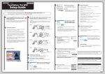
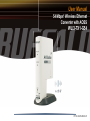
User Manual
54 Mbps* Wireless Ethernet
Converter with AOSS
WLI3-TX1-G54
PY00-30045-DM20-01
AOSS Installation
System Requirements
◗ Desktop or Notebook computer with an Ethernet (RJ-45) port (for configuration purposes).
◗ Web Browser 5.0 or later.
◗ 802.11b or 802.11g access point (Infrastructure Mode) OR a different computer with an
802.11b or 802.11g wireless adapter (Ad-hoc Mode).
AOSS Installation
If your Wireless Router/Access Point supports Buffalo's AOSS
technology, then it is recommended to use AOSS. If your Wireless Router/Access Point does not support AOSS technology,
then please skip to the next page. The following steps will guide
you through the AOSS process.
◗ Plug the Ethernet Converter's AC Adapter into a wall
outlet. Connect the power connector to the back of the Ethernet
Converter.
◗ After 30 seconds, the wireless light on the Ethernet Converter
will become solid. This signifies that the Ethernet Converter
startup process has completed.
◗ Refer to the Ethernet Converter's AOSS supplement to begin the AOSS setup procedure.
2
Conventional Installation
Other than using AOSS, there are two conventional ways to configure the Ethernet Converter. One method is to use the Ethernet Converter Manager software.
This method only works if there is a Windows 98SE/ME/2000/XP computer with a
CD-ROM drive available on a computer network. The alternative method does not
require software and works with any computer that has a Web Browser of 5.0 or
later; this includes Macintosh and Linux machines.
3
Configuration with Ethernet Converter Manager
If you have a Windows 98SE/ME/2000/XP machine with a CD-ROM drive available on your
computer network, it is recommended to use the Ethernet Converter Manager to configure the
Ethernet Converter. The following steps will guide you through configuring the Ethernet Converter via the Ethernet Converter Manager.
◗ With the included network patch cable, plug the Ethernet Converter's LAN port into an
open port on your network's router, or on on e of your network switches or hubs. If there are
no ports available, you can temporarily remove a computer or other connected device and
plug the Ethernet Converter to that port. You can plug the Ethernet Converter directly to the
configuring computer, but will have to use the manual configuration found on 'Page 8' of this
Manual.
◗ Once the network cable has been plugged in, plug the Ethernet Converter's AC Adapter into
an available power outlet. Then attach the power connector to the back of the Ethernet
Converter. The boot up process takes 30 seconds and can be confirmed completed
when both the Wireless and Ethernet lights are green.
◗ Return to the PC designated for configuration and
insert the included Ethernet Converter CD-ROM into
drive.
◗ The AirNavigator application should launch
automatically. If it does not, browse your CD-ROM
drive in Windows and run the launch.exe program.
4
the PC's CD-ROM
◗ Click on the text, 'Launch Setup'.
◗ The Ethernet Converter Manager software will run. Please select the
'Search for an Ethernet Converter' option from the 'Edit' drop down menu.
5
◗ The Ethernet Converter Manager will search for all
Buffalo Ethernet Converters on your network. The
process takes 15 seconds. Once completed, the
'Search Results' will appear.
◗ The 'Search Results' will list all Buffalo Ethernet
Converters on the network. If there is more than one
Ethernet Converter in the list, then select the Ethernet
Converter you would like to configure. Press the 'IP
Settings' button to continue configuration.
◗ Check the 'Use DHCP' checkbox and press the 'OK'
button. The Ethernet Converter will reboot; this process
takes 15 seconds. The Ethernet Converter Manager
will then re-scan the network for Ethernet Converters.
6
◗ The Ethernet Converter Manager Search
Results will appear. If more than one
Ethernet Converter is present, then select the
proper Ethernet Converter from the list.
Then press the 'Configure' button.
◗ The Ethernet Converter Manager will connect
you to the Ethernet Converter's web based
configuration. You will be prompted for a
username and password.
By default, the username is root and there
is no password.
◗ After entering the user name, press the 'OK'
button. Please skip to 'Page 10' to
continue configuration.
7
Configuration without Software
Configuration of the Ethernet Converter without software is possible. The following
steps will guide you through configuring your Ethernet Converter without software.
◗ Refer to your operating system documentation on how to configure a 'Static' IP
Address. The Ethernet Converter has an IP Address of 1.1.1.1 by default. Thus,
for successful configuration, the PC must be configured with 1.1.1.2 as its IP
Address.
◗ With the included network patch cable, plug the Ethernet Converter's LAN port
into an open port on your network's router, or on one of your network switches
or hubs. If there are no ports available, you can temporarily remove a computer
or other connected device and plug the Ethernet Converter to that port. You can
plug the Ethernet Converter directly to the configuring computer.
◗ Once the network cable has been plugged in, plug the Ethernet Converter's AC
Adapter into an available power outlet. Then attach the power connector to the
back of the Ethernet Converter. The boot up process takes 30 seconds and can
be confirmed completed when both the Wireless and Ethernet lights are green.
8
◗ Once your computer has a Static IP Address of 1.1.1.2, open your web browser
and access the web page http://1.1.1.1 by typing it into the 'Address' field and
pressing enter (as shown above).
◗ You will be prompted for a username and password.
By default, the username is root and there is no password.
◗ After entering the user name, press the 'OK' button.
9
Web-Based Configuration
The Web Based Configuration is where changes to the Ethernet Converter take place. Through
the Web Based Configuration you can
change the wireless network the Ethernet
Converter is associated with, the IP Address
of the Ethernet Converter, and other important settings.
◗ After logging in on the previous pages, you
will be greeted by the main configuration
page. This page quickly shows you what
network the Ethernet Converter is connected too as well as allowing you to search for
available networks.
◗ The first step in the Web Based Configuration should be to search for an available wireless
network. To do this, press the 'Search' button in the 'SSID (Network Name)' table.
◗ After pressing the 'Search' button, the
'Search for SSID' program will run. Select
the appropriate wireless network that you
would like to connect to and press the
'Select' button. If encryption is enabled on
the wireless network, you will need to enter
the encryption key on a future step.
10
◗ After selecting a wireless network to connect to, you will be returned to the main
Web Based Configuration page.
NOTE: If the wireless network you are attempting to connect to is not broadcasting its SSID, then you will be required to manually enter the SSID into the SSID
field. After it has been manually entered, then press the 'Apply Settings' button.
11
◗ The SSID field will be populated now. Depending
on whether or not the wireless network is using WEP
Encryption or not, the Encryption Key option may be
set to 'Encrypt' or 'No Encryption'. If it is set to
'No Encryption' then you are already connected
to the wireless network, and you may skip to the last
step on this page. If the Encryption Key option is
set to 'Encrypt' then you will need to enter the correct
encryption type and key and press the 'Apply
Settings' button. The drop down menu references the
type of encryption key used, either WEP, TKIP, or AES.
It is important that you know not only your encryption
key but also the type of key. Please consult your Router/Acess Point's wireless settings and
documentation for further information.
◗ The 'Finalize Connecting' page will appear. Press the 'Back' link.
◗ The main Web Based Configuration page will now list the connection information in the
'Wireless Connection Status' table.
12
◗ The Ethernet Converter configuration is complete. Disconnect the Ethernet
Converter from the network connection and power adapter, and move it to the
desired location.
◗ Plug the Ethernet Converter's LAN port into the wired device that requires the
wireless Ethernet Converter (devices could be an XBox, PS2, Home Theatre
Media Adapter, or another computer system). Plug the AC Adapter into a nearby
power outlet and connect the power connector to the Ethernet Converter. Power
cycle the network device that is connected to the Ethernet Converter.
◗ If you set a static IP address on your computer on 'Page 8', then reference the
operating system documentation to restore the IP settings to obtain an IP
Address automatically.
◗ For additional settings and features, please see the Ethernet Converter Manual
located on the Ethernet Converter CD-ROM.
13
Advanced Configuration
The Web Based Configuration also has several other settings to
customize the way the Ethernet Converter operates. To access
the Advanced Configuration settings, press the 'Advanced' button
on the main Web Based Configuration page. On all advanced
settings pages, the 'Apply Settings' button must be pressed
anytime changes are made to a configuration page.
Wireless Settings - This page contains the settings that affect
the wireless communication of the Ethernet Converter.
◗ Multiple Client Support - The multiple client support feature
allows a switch or hub to be connected to the Ethernet Converter, allowing multiple clients to use the Ethernet Converter
as their wireless connection. Enabling this feature allows
for this use, disabling allows for only one device to be used
behind the Ethernet Converter.
◗ SSID - The SSID is the name of the wireless device the
Ethernet Converter is connecting to. It can be typed in manually or it can be searched for by pressing the 'Search' button.
◗ Wireless Network Type - Select between the two wireless modes: Infrastructure (Access
Point Based) or Ad-hoc (Client to Client).
◗ Wireless Channel - The channel will be automatically selected in Infrastructure networks. For Adhoc networks, both clients must be set on the same channel.
14
◗ Wireless Mode - The wireless mode only applies to Ad-hoc connections. If the Ethernet
Converter is making an Ad-hoc connection with an 802.11b client, then select '802.11b' from
the drop down menu. If an 802.11g client is connecting to the Ethernet Converter then select
the 'Auto - 802.11g / 802.11b' option.
◗ Basic Rates - The basic rate set only applies to Ad-hoc connections. Select the proper rate
set for Ad-hoc client the Ethernet Converter is going to associate to. If you are unsure, it is
recommended to leave this setting set to 'Auto'.
◗ Frame Bursting - Frame Bursting technology allows for quicker wireless throughput speeds
by shortening the overhead in each wireless packet. It is recommended to leave it enabled,
as having it enabled presents no disadvantages in most network scenarios.
◗ Wireless Output Power - The wireless output power setting changes the power of the Ethernet Converter's internal radio. Reducing the output power can often reduce interference with
other devices. It is recommended to leave the output power set at 100% unless interference
with other networks or 2.4 GHz devices is apparent.
◗ Data Encryption - The data encryption table allows you to enter the necessary WEP or WPA
settings into the Ethernet Converter. This Ethernet Converter supports WEP 64, WEP 128,
TKIP, and AES. If WEP is selected, then a WEP key or series of WEP keys must be entered
into the WEP key field(s). Please select whether the specific key is ASCII or HEX from the pull
down list next to the key fields. If TKIP or AES is used, then enter the pre-shared key in the
WPA-PSK field.
15
Network Settings - This page contains the network IP Address
settings of the Ethernet Converter
◗ Automatic IP Assignment - This setting specifies the
Ethernet Converter to obtain its IP Address from a DHCP
server on the network. Consult with your network administrator regarding whether this device should obtain its IP
Address from a DHCP Server.
◗ Manual Assignment - This setting specifies the Ethernet Converter to operate on a specific
IP Address. This is often referred to as a Static IP Address. If a manual assignment is preferred, then you will be required to enter an appropriate IP Address and Subnet Mask for the
Ethernet Converter.
■ NOTE: The IP Address is required for configuring the Ethernet Converter. Be careful
when changing its address, as it may cause undesired operation. Also, please document any
changes and update any browser bookmarks that may be referencing the Ethernet Converter
Web Based Configuration.
◗ The Ethernet Converter Manager may be used to set the IP Address in the event of changing
the IP Address inappropriately.
◗ The IP Address does not need to be in the range of the DHCP server's scope to successfully
pass DHCP requests to the network client behind the Ethernet Converter.
16
System Information - This page contains a summary of the Ethernet Converter's settings.
◗ The tables present a summary of the settings on the Ethernet
Converter. Settings cannot be changed from this page. If the
Ethernet Converter is obtaining its IP Address from a DHCP
server, then a release and renew button will be present at the
bottom of the page. Releasing the IP Address will make the
Ethernet Converter impossible to configure without re-initializing the device or using the Ethernet Converter Manager. Only
release the IP Address if you are certain you want to do so.
Name and Password - This page contains settings that affect the
naming and password protection of the Ethernet Converter.
◗ Ethernet Converter Name - The Ethernet Converter name
is a quick reference name for the Ethernet Converter. It is
only used for the naming of Ethernet Converters in the Ethernet Converter Manager.
◗ Administrator Password - The administrator password is
used to protect the Ethernet Converter from unwanted configuration changes. Setting the password protects configuration changes from both the Web Based Configuration and the Ethernet Converter Manager. It is important to document the password after it has been set. If the password is
lost, the Ethernet Converter must be re-initialized. The password must be entered twice, once for
verification purposes.
17
◗ Configuration Limitations - The configuration limitations of the Ethernet Converter specify
what types of clients can configure the Ethernet Converter through the Web Based Configuration. Prohibiting configuration from either wireless or wired clients can have negative
effects on your ability to access the Web Based Configuration. Please be certain of your
setting changes. Prohibiting configuration from wireless clients creates a rule that says any
client that is connected to the Ethernet Converter wirelessly cannot access its Web Based
Configuration. Prohibiting configuration from wired clients creates a rule that says any client that is hard wired into the Ethernet Converter's LAN port cannot access its Web Based
Configuration. Prohibiting both configurations makes all Web Based Configuration attempts
impossible. The Ethernet Converter must then be re-initialized to restore configuration capabilities.
Initialization and Reboot - This page contains settings that
restart and re-initialize the Ethernet Converter.
◗ Initialize - Initializing the Ethernet Converter restores the
Ethernet Converter's settings to the default settings. This will
erase all configuration changes made, and the setup will have
to be restarted as if the product was brand new. This will erase
any passwords as well. Re-initialization can also occur without
logging into the Ethernet Converter. Please see the troubleshooting section for that procedure.
◗ Restart - Restarting the Ethernet Converter performs a simple restart similar to what would occur
if the power was cycled on the Ethernet Converter. No settings are lost in this case. The restart
process takes 30 seconds and can be confirmed complete when the wireless light is green.
18
Firmware Update - This page contains settings that update the
Ethernet Converter's Firmware.
◗ Updating the Ethernet Converter's firmware is a procedure
where a user downloads a newer firmware from the Buffalo Technology Web Site and applies it to the Ethernet Con
verter. New firmware files contain new software code that
adds bug fixes, additional features, increased performance,
and revised interfaces.
◗ To update the firmware, press the 'Browse' button and search for the downloaded firmware file.
When complete, press the 'Firmware Update' button. The firmware update process takes 90
seconds. After the firmware update is complete any previous configuration changes will remain
unchanged.
19
Troubleshooting
Troubleshooting - Below are some common troubleshooting tips:
◗ Re-initializing the Ethernet Converter - Re-initializing the Ethernet Converter is the process
of returning the Ethernet Converter to default settings. This process is used if you cannot
access configuration anymore, have lost the password to the Ethernet Converter, or desire to
return the settings to the factory settings.
To re-initialize the device, simply press the red INIT button on the underside of the Ethernet
Converter for 5 seconds or until the AOSS light becomes red. The entire process takes 30
seconds. Afterwards, refer to the Quick Setup Guide to restart the configuration process of
the Ethernet Converter.
20
Technical Support
USA&Canada
Please have your Proof of Purchase when calling Buffalo Technical Support.
Buffalo Technology offers toll-free technical support 24 hours a day, 7 days a week for this product. Customers in
the United States and Canada can obtain technical support using the following information:
◗ Web
◗ E-mail:
◗ Telephone
www.buffalotech.com/wireless
[email protected]
866-752-6210
Europe
Please have your Proof of Purchase when calling Buffalo Technical Support.
Europian Technical Support is available between the hours of 9am-6pm (GMT) Monday to Thursday and 9am4:30pm (GMT) Friday for this product. Customers in Europe can obtain Technical Support using the following
information:
◗ Web
◗ E-mail
◗ Telephone
www.buffalo-technology.com
[email protected]
UK only: 08712 50 12 60
Elsewhere: +353 61 708 050
The constantly evolving state of wireless products and operating systems requires Buffalo Technology to
occasionally release updated software to take advantage of new technologies and to comply with industry
standards. For the most recent software, firmware, driver, and technical whitepaper releases available, please visit
the Buffalo Technology website.
21
FCC / CE / R&TTE
Federal Communication Commission Interference Statement
This equipment has been tested and found to comply with the limits for a Class B digital device,
pursuant to Part 15 of the FCC Rules. These limits are designed to provide reasonable protection
against harmful interference in a residential installation. This equipment generates, uses and can
radiate radio frequency energy and, if not installed and used in accordance with the instructions, may
cause harmful interference to radio communications. However, there is no guarantee that interference
will not occur in a particular installation. If this equipment does cause harmful interference to radio
or television reception, which can be determined by turning the equipment off and on, the user is
encouraged to try to correct the interference by one of the following measures:
• Reorient or relocate the receiving antenna.
• Increase the separation between the equipment and receiver.
• Connect the equipment into an outlet on a circuit different from that to which the receiver is connected.
• Consult the dealer or an experienced radio/TV technician for help.
FCC Caution: To assure continued compliance, (example - use only shielded interface cables when
connecting to computer or peripheral devices). Any changes or modifications not expressly approved
by the party responsible for compliance could void the user’s authority to operate this equipment.
This device complies with Part 15 of the FCC Rules. Operation is subject to the following two conditions:
(1) This device may not cause harmful interference, and (2) this device must accept any interference
received, including interference that may cause undesired operation.
22
FCC / CE / R&TTE
IMPORTANT NOTE:
FCC RF Radiation Exposure Statement:
This equipment complies with FCC RF radiation exposure limits set forth for an uncontrolled
environment. This equipment should be installed and operated with a minimum distance of 20
centimeters between the radiator and your body.
This transmitter must not be co-located or operating in conjunction with any other antenna or
transmitter.
Europe – EU Declaration of Conformity
This device complies with the essential requirements of the R&TTE Directive 1999/5/EC. The following
test methods have been applied in order to prove presumption of compliance with the R&TTE Directive
1999/5/EC:
◗ EN 60950: 2000
Safety of Information Technology Equipment
◗ EN 300 328-2 V1.2.1 (2001-12)
Technical requirements for spread-spectrum radio equipment
◗ EN 301 489-17 V1.1.1 (2000-09)
EMC requirements for spread-spectrum radio equipment
23
FCC / CE / R&TTE
Safety
This equipment is designed with the utmost care for the safety of those who install and use it.
However, special attention must be paid to the dangers of electric shock and static electricity when
working with electrical equipment. All guidelines of this manual and of the computer manufacturer
must therefore be allowed at all times to ensure the safe use of the equipment.
Intended use
This device is a 2.4 GHz wireless LAN transceiver, intended for indoor home and office use in USA,
Canada, all EU and EFTA member states.
EU Countries intended for use
This device is intended for indoor Home and office use in the following countries:
Austria, Belgium, Germany, Denmark, Spain, Greece, France, Finland, Italy, Ireland, Luxembourg,
The Netherlands, Portugal, Sweden, United Kingdom, Cyprus, Czech Republic, Estonia, Hungry,
Latvia, Lithuania, Malta, Poland, Slovak Republic and Slovenia.
The device is also authorised for use in all EFTA member states Iceland, Liechtenstein, Norway and
Switzerland.
EU countries not intended for use
None
24
FCC / CE / R&TTE
Potential restrictive use
This device is a 2.4 GHz wireless LAN transceiver, intended for indoor home and office use in all
EU and EFTA member states, except in France, Belgium and Italy where restrictive use applies.
In Italy the end-user should apply for a license at the national spectrum authorities in order to obtain
an authorization to use the device for setting up outdoor radio links.
In Belgium there is a restriction in outdoor use. The frequency range in which outdoor operation in
Belgium is permitted is 2460 – 2483.5 MHz.
In France only channels 10,11,12 and 13 are available.
This device may not be used for setting up outdoor radio links in France. For more information see
http://www.anfr.fr/ and/or http://www.art-telecom.fr
* 54 Mbps is the IEEE 802.11g standard theoretical maximum data transfer rate. Actual wireless network throughput is limited
by environmental and system factors and will be less.
Copyright © 2004 Buffalo Technology, Inc. All Rights Reserved.
Buffalo Technology (USA) Inc., is part of Buffalo Inc. (JAPAN), the global manufacturers of IT peripherals, including memory,
networking, and multimedia products, inside many of the world's computers. All trademarks are property of their respective
owners.
25
Warranty
BUFFALO WARRANTY STATEMENT
This Buffalo product comes with a 2-year limited warranty from the date of purchase. Buffalo Technology
(Buffalo Inc) warrants in good operating condition for the warranty period. This warranty does not include
non-Buffalo Technology (Buffalo Inc) installed components. If the Buffalo product malfunctions during
the warranty period, Buffalo Technology will, at its discretion, repair or replace the product at no charge,
provided the product has not been subjected to misuse, abuse or non-Buffalo Technology (Buffalo Inc)
authorized alterations, modifications or repairs. When returning a product, include your original proof of
purchase. Return requests cannot be processed without proof of purchase. Shipment of returned product
to Buffalo Technology is the responsibility of the purchaser. All expressed and implied warranties for the
Buffalo product line including, but not limited to, the warranties of merchantability and fitness for a particular
purpose, are limited in duration to the above period.
Under no circumstances shall Buffalo Technology (Buffalo Inc) be liable in any way to the user for
damages, including any lost profits, lost savings or other incidental or consequential damages arising out of
the use of, or inability to use, the Buffalo products.
Buffalo Technology (Buffalo Inc) shall have no responsibility for any such data and shall have no liability
arising out of any damage to or loss of such data while the product is in the user’s possession.
Buffalo Technology (Buffalo Inc) reserves the right to revise or update its products, software, or
documentation without obligation to notify any individual or entity.
26
<Important Notice>
Please have your proof of purchase receipt to get warranty support. All defective products shall be returned
with a copy of proof of purchase.
In no event shall Buffalo Technology (Buffalo Inc)’s liability exceed the price paid for the product from
direct, indirect, special, incidental, or consequential damages resulting from the use of the product, its
accompanying software, or its documentation. Buffalo Technology (Buffalo Inc) does not offer refunds for
any product.
Buffalo Technical Support Information:
(Please have your Proof of Purchase when calling Buffalo Technical Support.)
[United States of America and Canada]
BUFFALO TECHNOLOGY (USA), INC.
4030 West Braker Lane, Suite 350
Austin, TX 78759-5319
http://www.buffalotech.com/support
[Europe]
BUFFALO TECHNOLOGY (UK) LTD.
176 Buckingham Avenue, Slough, Berkshire
SL1 4RD, United Kingdom
24hours a day, 7days a week
TEL: (866) 752-6210
e-mail: Please visit the below web site.
Monday to Thursday, 9am-6pm GMT,
Monday to Friday, 9am-4:30pm GMT,
TEL: 353-61-708-050
TEL: 08712 50 12 60 (UK only)
e-mail: [email protected]
27