1
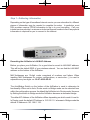
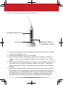
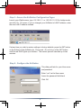
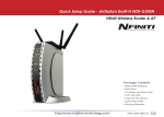
Quick Setup Guide
AirStation WHR-HP-G54 High-Power
Wireless Cable/DSL Smart Router
Preparation
This Quick Setup Guide will guide you through installing your new Buffalo router. For
advanced setup and configuration instructions, please refer to the Product Manual,
available on the AirNavigator CD-ROM or from the Buffalo Support Web Page.
Package Contents Checklist
Wireless Cable/DSL Router (WHR-HP-G54)
External Antenna
Utility CD-ROM w/ User Manual
Quick Setup Guides
AC Adapter
Power Cable
Base Plate
2.5m Ethernet Cable
Warranty Statement
If any of the contents are missing or damaged, please contact the retailer or reseller
from which this product was purchased.
www.buffalo-technology.com
PY00-31028-DM20-02 2-01
Step 1 - Gathering Information
Depending on the type of broadband internet service you are subscribed to, different
pieces of information may be needed to complete the setup. In particular, most
DSL providers require PPPoE information to log in to your connection. Call your
internet service provider’s customer or technical support number to find if any special
information is required for you to connect to the internet.
Recording the AirStation’s LAN MAC Address
Before you place your AirStation, it’s a good idea to record its LAN MAC address.
This will be the default SSID of your wireless network. You can find the LAN MAC
address on the bottom of the AirStation.
MAC Addresses are 12-digit codes comprised of numbers and letters. When
inputting MAC Addresses for custom configurations, a semi-colon (:) is used to
separate every two digits. ex: 00:07:40:00:00:00
The Auto/Bridge Switch on the bottom of the AirStation is used to determine its
functionality. When set to Auto, Router mode or Bridge mode can be selected from
within the configuration screens. As default the AirStation is in Router mode. However
by flicking the switch to Bridge mode the AirStation becomes a dedicated bridge.
The default IP Address of the AirStation differs depending on which mode it is set to.
In Router mode the default IP Address is 192.168.11.1 whereas in Bridge mode the
default IP Address is 192.168.11.100.
2
Step 2 - Connecting Cables to the AirStation
Ethernet cable to PC
Ethernet cable to
Cable/DSL modem
AC power
1. Power down the Cable or DSL modem and the computer which will be used to
configure the AirStation router.
2. Screw external antenna on to top of AirStation.
3. Plug the Cable or DSL’s LAN Ethernet cable into the AirStation’s WAN port.
Initially, you may need to unplug this cable from your computer, hub or other
router.
4. Plug the provided Ethernet cable into a LAN port on the AirStation and plug the
other end into your computer’s Ethernet adapter’s (NIC) port. If you plan to
initially configure the AirStation wirelessly (not recommended), you may skip
this step.
5. Power on your cable or DSL modem and wait one full minute, then power on
the AirStation router (by plugging in its power) and wait another minute, and
finally power on the computer which will be used to configure the AirStation. If
the red DIAG light on the AirStation is lit or flashing after several minutes of
being powered on, please consult Buffalo Technology Technical Support.
3
Notes on Wireless Configuration:
If you have a PC connected to the router with a wired connection, we recommend
that you use it to configure your AirStation. That said, if necessary, you can still
configure your AirStation with a wireless connection.
Consult your wireless client card or adapter’s documentation to confirm that it’s
correctly installed with all necessary drivers.
Does your client support AOSS? If so, configuration is very simple. Just push
the AOSS button on your router, push the AOSS button on your client, and voilá,
15 seconds later, your wireless network will be configured. Consult your AOSS
suppliments for more information on how to use AOSS.
The default SSID of the AirStation is its LAN MAC Address, addressed on page 2
of this Quick Setup Guide. Using your wireless card’s software or Windows XP’s
Wireless Zero Config, connect to the Wireless Network that broadcasts the LAN
MAC Address of your AirStation as its SSID.
Out of the box, the AirStation router does not have any encryption set up, so
initially disable any encryption settings in your wireless adapter’s configuration.
Please consult the documentation that came with your wireless client card or
adapter for further assistance.
4
Step 3 - Configure your Computer’s IP Address
For Windows 98SE/ME:
• Right-click on Network Neighborhood or My Network Places and select
Properties.
• Select the Configuration tab, scroll down to TCP/IP and press Properties.
• Select Obtain IP address automatically and Obtain DNS Server address
automatically.
• Click OK to close Internet Protocol (TCP/IP) Properties.
• Click OK to close Network Connection Properties.
• Close Network Connections window.
For Windows 2000/XP:
• Click Start => Settings => Control Panel.
• Double click on the Network Connections icon.
• Right-click on Local Area Network Connection and select Properties.
NOTE: If you’re using a wireless connection, right-click on its icon and select
Properties.
• Scroll down to Internet Protocol (TCP/IP ) and press Properties.
• Select Obtain IP address automatically and Obtain DNS Server address
automatically if they’re not already selected.
• Click OK to close Internet Protocol (TCP/IP) Properties.
• Close Network Connections and Control Panel windows.
Refer to your Operating System documentation for further instructions on how to
navigate to your TCP/IP Properties.
5
Step 4 - Access the AirStation Configuration Pages
Launch your Web browser, type 192.168.11.1 or 192.168.11.100 if in bridge mode,
and click Go. Of course, if you’ve changed your AirStation’s LAN IP address, enter
the new LAN IP address instead.
If at any time you wish to restore settings to factory defaults, press the INIT button
on the bottom of the AirStation for 15 seconds. Do not let go of the INIT button
until the red DIAG lights up or flashes. The restore process can take up to two
minutes.
Step 6 - Configure the AirStation
This dialog will ask for your User name
and password.
Enter “root” as the User name.
Leave the password field blank.
Click OK.
6
The WHR-HP-G54 will automatically detect whether your internet is from a DSL or
Cable provider and ask you for any necessary information.
◗ DSL
If you have a DSL connection, you will probably have to enter your PPPoE login
information. Get this information from your ISP if you don’t know it.
◗ Cable
Most Cable providers require no aditional settings to obtain an IP address. If your
connection requires a DNS server to be set up manually, a wizard will ask you for
the necessary information. Get it from your cable provider if you don’t know it.
Default Settings
If at any time you wish to restore your AirStation’s settings to factory defaults,
press the INIT button on the bottom of the AirStation for 15 seconds. Do not let go
of the INIT button until the red DIAG lights up or flashes. The restore process can
take up to two minutes.
This completes the basic AirStation Configuration. To change advanced settings,
please consult the Online Manual on the CD-ROM or go to the Buffalo Support
Web Site: http://www.buffalo-technology.com
The AirStation can be re-configured anytime via a Web browser using a wired or
wireless connection by entering 192.168.11.1 or 192.168.11.100 if in bridge mode,
in the URL address field of the Web browser and pressing the Enter key on the
keyboard. Of course, if you’ve changed your AirStation’s LAN IP address, enter
the new LAN IP address instead.
7
Additional Information:
AOSS (AirStation One-Touch Secure System)
The WHR-HP-G54 supports Buffalo’s AOSS system for connecting AOSS
compatible wireless clients to the WHR-HP-G54. For information about AOSS,
please refer to the AOSS Supplement which is included in the WHR-HP-G54
package contents.
IP Addressing
To verify your IP settings for static or automatic addressing, click Start, select
Settings (if present) and click Control Panel. Within Control Panel, double-click
Network or Network Connections. You can then right-click on any of your wired or
wireless connections and select Properties. Within the properties, you can view the
properties of your TCP/IP protocol.
Generally, you will want to be sure that Obtain an IP address automatically
is selected to allow easier connections. To manually renew IP addressing
configurations for your connection, follow these steps:
• Click Start and Run. A dialog box will appear where you can type cmd into
the field provided and click OK.
• An MS-DOS prompt will launch. Enter IPCONFIG /RELEASE and press the
Enter key on the keyboard to release your current IP configuration. Next,
enter IPCONFIG /RENEW and press the Enter key to seek new settings from
a DHCP server. (This may take a few moments).
• Type IPCONFIG /ALL. This will display all the IP configurations for your wired
or wireless connection.
• The Default Gateway address listed in the results is usually the IP address of
the AirStation. If no IP addresses are listed or your wireless adapter displays
a 169.254.XXX.XXX address, retrace the setup steps to verify correct
installation.
• Type EXIT to close out the DOS window.
8
Warning : Please note it is not permitted under EU Legislation to use external
antennas with the WHR-HP-G54.
9
Buffalo Technology Technical Support
Buffalo Technology offers Technical Support between the hours of 9am-6pm
(GMT) Monday to Thursday and 9am-4:30pm (GMT) Friday for this product.
Customers in Europe can obtain Technical Support using the following
information:
◗ Online Help
◗ Web
◗ E-mail
◗ Telephone
Available on the enclosed AirNavigator CD.
www.buffalo-technology.com
[email protected]
UK only: 08712 50 12 60
Elsewhere: +353 61 708 050
The constantly evolving state of wireless products and operating systems
requires Buffalo Technology to occasionally release updated software to take
advantage of new technologies and to comply with industry standards. For
the most recent software, firmware, driver, and technical whitepaper releases
available, please visit the Buffalo Technology website: www.buffalo-technology.
com
Europe – EU Declaration of Conformity
This device complies with the essential requirements of the R&TTE Directive
1999/5/EC. The following test methods have been applied in order to prove
presumption of compliance with the R&TTE Directive 1999/5/EC:
◗ EN 60950: 2000
Safety of Information Technology Equipment
◗ EN 300 328-2 V1.2.1 (2001-12)
Technical requirements for spread-spectrum radio equipment
◗ EN 301 489-17 V1.1.1 (2000-09)
EMC requirements for spread-spectrum radio equipment.
10
Intended use
This device is a 2.4 GHz wireless LAN transceiver, intended for indoor home
and office use in all EU and EFTA member states.
EU Countries intended for use
This device is intended for indoor Home and office use in the following countries:
Austria, Belgium, Germany, Denmark, Spain, Greece, France, Finland, Italy,
Ireland, Luxembourg, The Netherlands, Portugal, Sweden, United Kingdom,
Cyprus, Czech Republic, Estonia, Hungry, Latvia, Lithuania, Malta, Poland,
Slovak Republic and Slovenia.
The device is also authorised for use in all EFTA member states Iceland,
Liechtenstein, Norway and Switzerland.
EU countries not intended for use
None
Potential restrictive use
This device is a 2.4 GHz wireless LAN transceiver, intended for indoor home
and office use in all EU and EFTA member states, except in France, Belgium
and Italy where restrictive use applies.
In Italy the end-user should apply for a license at the national spectrum
authorities in order to obtain an authorization to use the device for setting up
outdoor radio links.
In Belgium there is a restriction in outdoor use. The frequency range in which
outdoor operation in Belgium is permitted is 2460 – 2483.5 MHz.
This device may not be used for setting up outdoor radio links in France. For
more information see http://www.anfr.fr/ and/or http://www.art-telecom.fr
* When operating in High Speed Mode™, this Wi-Fi device achieves an actual throughput of up to 34.1Mbps, which
is the equivalent throughput of a system following 802.11g protocol and operating at a signaling rate of 125Mbps.
11
BUFFALO WARRANTY STATEMENT
Buffalo products come with a 2-year limited warranty from the date of purchase.
Buffalo Technology warrants in good operating condition for the warranty period.
This warranty does not include non-Buffalo Technology installed components. If the
Buffalo product malfunctions during the warranty period, Buffalo Technology will, at
its discretion, repair or replace the product at no charge, provided the product has
not been subjected to misuse, abuse or non-Buffalo Technology authorized alterations,
modifications or repairs. When returning a product, include your original proof of
purchase. Return requests cannot be processed without proof of purchase. Shipment
of returned product to Buffalo Technology is the responsibility of the purchaser. All
expressed and implied warranties for the Buffalo product line including, but not limited
to, the warranties of merchantability and fitness for a particular purpose, are limited in
duration to the above period.
Under no circumstances shall Buffalo Technology be liable in any way to the user for
damages, including any lost profits, lost savings or other incidental or consequential
damages arising out of the use of, or inability to use, the Buffalo products.
Buffalo Technology reserves the right to revise or update its products, software, or
documentation without obligation to notify any individual or entity.
Important Notice
Please have your proof of purchase receipt to get warranty support. All defective
products shall be returned with a copy of proof of purchase.
In no event shall Buffalo Technology’s liability exceed the price paid for the product
from direct, indirect, special, incidental, or consequential damages resulting from the use
of the product, its accompanying software, or its documentation. Buffalo Technology
does not offer refunds for any product.
BUFFALO TECHNOLOGY UK LTD
176, Buckingham Avenue,Slough, Berkshire, SL1 4RD United Kingdom
E-mail: [email protected]
Copyright © 2005 Buffalo Technology UK, Ltd. All Rights Reserved. - Buffalo Technology UK, Ltd. is part of
BUFFALO INC., the global manufacturers of IT peripherals, including memory, networking, and multimedia
products, inside many of the world’s computers. All trademarks are the property of their respective owners.
12