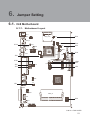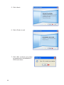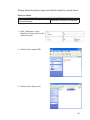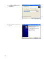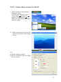
1
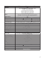
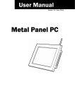
USER MANUAL
VERSION 1.3 June 2012
Metal Panel PC
Hardware System
Copyright 2012
All Rights Reserved
Manual Version 1.3
Part Number: 3LMKK7500113
The information contained in this document is subject to change without notice.
We make no warranty of any kind with regard to this material, including, but not
limited to, the implied warranties of merchantability and fitness for a particular
purpose. We shall not be liable for errors contained herein or for incidental or
consequential damages in connection with the furnishing, performance, or use of
this material.
This document contains proprietary information that is protected by copyright. All
rights are reserved. No part of this document may be photocopied, reproduced
or translated to another language without the prior written consent of the
manufacturer.
TRADEMARK
Intel®, Pentium® and MMX are registered trademarks of Intel® Corporation.
Microsoft® and Windows® are registered trademarks of Microsoft Corporation.
Other trademarks mentioned herein are the property of their respective owners.
Safety
IMPORTANT SAFETY INSTRUCTIONS
1. To disconnect the machine from the electrical power supply, turn off the power
switch and remove the power cord plug from the wall socket. The wall socket must
be easily accessible and in close proximity to the machine.
2. Read these instructions carefully. Save these instructions for future reference.
3. Follow all warnings and instructions marked on the product.
4. Do not use this product near water.
5. Do not place this product on an unstable cart, stand, or table. The product may fall,
causing serious damage to the product.
6. Slots and openings in the cabinet and the back or bottom are provided for
ventilation to ensure reliable operation of the product and to protect it from
overheating. These openings must not be blocked or covered. The openings
should never be blocked by placing the product on a bed, sofa, rug, or other
similar surface. This product should never be placed near or over a radiator or heat
register or in a built-in installation unless proper ventilation is provided.
7. This product should be operated from the type of power indicated on the marking
label. If you are not sure of the type of power available, consult your dealer or local
power company.
8. Do not allow anything to rest on the power cord. Do not locate this product where
persons will walk on the cord.
9. Never push objects of any kind into this product through cabinet slots as they
may touch dangerous voltage points or short out parts that could result in a fire or
electric shock. Never spill liquid of any kind on the product.
ii
CE MARK
This device complies with the requirements of the EEC directive 2004/108/EC with
regard to “Electromagnetic compatibility” and 2006/95/EC “Low Voltage Directive”.
FCC
This device complies with part 15 of the FCC rules. Operation is subject to the
following two conditions:
(1) This device may not cause harmful interference.
(2) This device must accept any interference received, including interference that
may cause undesired operation.
CAUTION ON LITHIUM BATTERIES
There is a danger of explosion if the battery is replaced incorrectly. Replace only
with the same or equivalent type recommended by the manufacturer. Discard used
batteries according to the manufacturer’s instructions.
Battery Caution
Risk of explosion if battery is replaced by an incorrectly type. Dispose of used
battery according to the local disposal instructions.
Safety Caution
Note: To comply with IEC60950-1 Clause 2.5 (limited power sources, L.P.S)
related legislation, peripherals shall be 4.7.3.2 “Materials for fire enclosure”
compliant.
4.7.3.2 Materials for fire enclosures
For MOVABLE EQUIPMENT having a total mass not exceeding 18kg.the material
of a FIRE ENCLOSURE, in the thinnest significant wall thickness used, shall be of
V-1 CLASS MATERIAL or shall pass the test of Clause A.2.
For MOVABLE EQUIPMENT having a total mass exceeding 18kg and for all
STATIONARY EQUIPMENT, the material of a FIRE ENCLOSURE, in the thinnest
significant wall thickness used, shall be of 5VB CLASS MATERIAL or shall pass the
test of Clause A.1
iii
LEGISLATION AND WEEE SYMBOL
2002/96/EC Waste Electrical and Electronic Equipment Directive on the treatment,
collection, recycling and disposal of electric and electronic devices and their
components.
The crossed dust bin symbol on the device means that it should not be disposed
of with other household wastes at the end of its working life. Instead, the device
should be taken to the waste collection centers for activation of the treatment,
collection, recycling and disposal procedure.
To prevent possible harm to the environment or human health from uncontrolled
waste disposal, please separate this from other types of wastes and recycle it
responsibly to promote the sustainable reuse of material resources.
Household users should contact either the retailer where they purchased this
product, or their local government office, for details of where and how they can
take this item for environmentally safe recycling.
Business users should contact their supplier and check the terms and conditions of
the purchase contract.
This product should not be mixed with other commercial wastes for disposal.
iv
Revision History
Changes to the original user manual are listed below:
Revision Description
1.0
1.1
1.2
1.3
•
•
•
•
Initial release
IdeaCom touch driver installation added
C68 MB added
C56 MB added
Date
April 2011
June 2011
March 2012
June 2012
v
Table of Contents
1. Packing List .............................. 1
1-1. Standard Items ........................................................1
1-2. Optional Items .........................................................2
2. System View ............................. 3
2-1.
2-2.
2-3.
2-4.
Front & Side View ....................................................3
Rear View ................................................................3
I/O view....................................................................4
Dimensions .............................................................5
2-4-1.
2-4-2.
2-4-3.
2-4-4.
10.1" System ............................................................ 5
15.6" System ............................................................ 6
18.5" System ............................................................ 6
21.5" System ............................................................ 6
3. System Assembly .................... 7
3-1. Open the Chassis Cover .........................................7
3-2. RAM Module Replacement......................................8
3-3. HDD Replacement...................................................9
4. Peripheral Installation ............ 11
4-1. MSR Installation ..................................................... 11
4-2. Stand Installation ....................................................12
4-3. Cash Drawer Installation ........................................13
vi
5. Specification ........................... 15
6. Jumper Setting ........................ 21
6-1. C48 Motherboard....................................................21
6-1-1. Motherboard Layout ................................................ 21
6-1-2. Connectors & Functions ........................................... 23
6-1-3. Jumper & BIOS/Utility Setting ................................. 24
6-2. C68 Motherboard....................................................30
6-2-1. Motherboard Layout ................................................ 30
6-2-2. Connectors & Functions .......................................... 31
6-2-3. Jumper Setting ........................................................ 32
6-3. C56 Motherboard....................................................37
6-3-1. Motherboard Layout ................................................ 37
6-3-2. Connectors & Functions .......................................... 38
6-3-3. Jumper Setting ........................................................ 39
6-4. IdeaCom Touch Driver Installation..........................43
6-4-1. Gesture Setup example for WinXP........................... 47
6-4.2. Gesture Setup example for Win7.............................. 51
Appendix: Drivers Installation .... 55
vii
The page is intentionally left blank.
viii
1.
1-1.
Packing List
Standard Items
a.
b.
c.
d.
e.
f.
g.
a.
b.
c.
d.
e.
f.
g.
System
Power adapter
Driver bank
Power cord
User manual
RJ45-DB9 cable (x2)
Allen wrench
Note: Power cord will be supplied differently according to various region or country.
1
1-2.
Optional Items
MSR
2
2.
System View
2-1.
Front & Side View
2
3
4
1
1. Touch screen
2. Built-in web cam
2-2.
3. Ventilation
4. MSR cable hole
Rear View
K757 / K758 / K759
K755
5
5
7
6
6
5. VESA mounting holes
6. Cable cover
7. Safety label
3
2-3.
I/O view
m
C48 Motherboard
a
b c d e
Item No.
a
b
c
d
e
f
g
h
i
j
k
l
m
g
f
h
j
i
k
Description
DC IN
LAN
Cash drawer
MIC IN
Line out
COM port 1, 2, 3, 4 (from left to right)
USB(x4)
Printer
Power button
VGA
HDD 5V
SATA (e-SATA)
HDD slot
C68 Motherboard
a b
Item No.
a
b
c
d
e
f
g
h
i
j
k
4
c
d e
f
g
h
i
Description
MIC IN
DC IN
LAN (x2)
Cash drawer
Line Out
COM port 1, 2, 3, 4 (from left to right)
USB(x4)
Printer
Power button
VGA
HDD slot
j
k
l
C56 Motherboard
a
b
Item No.
a
b
c
d
e
f
g
h
i
d
e
f
g
h
i
Description
2nd power button
Power button
DC IN
VGA)
COM port 1, 2, 3, 4 (from left to right)
LAN
USBx4 (two optional USB)
Cash drawer
USB(x2)
Dimensions
2-4-1. 10.1" System
263mm
170mm
2-4.
c
38mm
5
2-4-2. 15.6" System
245mm
396mm
48mm
2-4-3. 18.5" System
284mm
464mm
48mm
2-4-4. 21.5" System
328mm
536mm
48mm
6
3.
System Assembly
3-1.
Open the Chassis Cover
The motherboard and RAM module can be replaced by opening the chassis
cover, which is located on the back side of the system. Please follow the steps
below to open the chassis cover.
1. Turn to the back side of the
system and loosen the thumb
screws (x2) to release the cable
cover first.
2. Loosen the hex socket cap
screws (x8) to open the back
cover of the system.
* An allen wrench is included in
the package for simple assembly.
Please use it to tighten/loosen the
screws.
7
3-2.
RAM Module Replacement
To remove and replace the RAM module, please open the chassis cover firstly
as steps dscribed in chapter 3-1.
Removing a RAM module
1. Find the memory slot at the right side of the motherboard.
C48 Motherboard
C68 Motherboard
C56 Motherboard
2. Flip the ejector clips outwards to remove the memory module from the memory
slot.
8
Installing a RAM moudle
3. Slide the memory module into the memory slot and press down until the
ejector clips snaps in place.
3-3.
HDD Replacement
To remove and replace the HDD, please open the cable cover firstly as stpes
dscribed in chapter 3-1-1.
K757 / K758 / K759
1. Find the HDD located at the right
side.
2. Pull the HDD tray from the system. For easier removal pull the
plastic sheet (see picture) at the
same time.
9
3. Attach the HDD to the HDD tray
and slide it into the slot until it
snaps in place.
*
Please note the top of the HDD
should be on the upper side.
K755
1. Loosen the screws(x2) to remove
the HDD bracket from the system.
2. The HDD is secured by the bracket,
remove the screws(x2) to release
the bracket and replace the HDD.
10
4.
4-1.
Peripheral Installation
MSR Installation
To install MSR, please open the cable cover firstly as steps described in chapter
3-1-1.
1. Insert MSR module in place and
fasten the screws (x2) on the back to
secure the module.
2. Connect MSR cable to the connector
on system side.
2. Close the cable cover and fasten
screws (x2). Make sure the MSR
cable is threaded through the MSR
cable hole on the system.
11
4-2.
Stand Installation
1. Place the system face down.
Make sure not to scrath the
screen.
2. Attach the stand to the back
of the system.
3. Fasten the screws(x4) to
secure the stand.
12
4-3.
Cash Drawer Installation
You can install a cash drawer through the cash drawer port. Please verify the pin
assignment before installation.
Cash Drawer Pin Assignment
6
Pin
1
2
3
4
5
6
1
Signal
GND
DOUT bit0
DIN bit0
12V / 19V
DOUT bit1
GND
Cash Drawer Controller Register
The Cash Drawer Controller use one I/O addresses to control the Cash Drawer.
Register Location: 48Ch
Attribute: Read / Write
Size: 8bit
BIT
BIT7
Attribute Reserved
BIT6
Read
BIT5
BIT4
Reserved
BIT3
BIT2
Write
BIT1
BIT0
Reserved
7 6 5 4 3 2 1 0
X
X X
X X
Reserved
Cash Drawer “DOUT bit0” pin output control
Cash Drawer “DOUT bit1” pin output control
Reserved
Cash Drawer “DIN bit0” pin input status
Reserved
13
Bit 7: Reserved
Bit 6: Cash Drawer “DIN bit0” pin input status.
= 1: the Cash Drawer closed or no Cash Drawer
= 0: the Cash Drawer opened
Bit 5: Reserved
Bit 4: Reserved
Bit 3: Cash Drawer “DOUT bit1” pin output control.
= 1: Opening the Cash Drawer
= 0: Allow close the Cash Drawer
Bit 2: Cash Drawer “DOUT bit0” pin output control.
= 1: Opening the Cash Drawer
= 0: Allow close the Cash Drawer
Bit 1: Reserved
Bit 0: Reserved
Note: Please follow the Cash Drawer control signal design to control the Cash
Drawer.
Cash Drawer Control Command Example
Use Debug.EXE program under DOS or Windows98
Command
Cash Drawer
O 48C 04
Opening
O 48C 00
Allow to close
► Set the I/O address 48Ch bit2 =1 for opening Cash Drawer by “DOUT bit0” pin
control.
► Set the I/O address 48Ch bit2 = 0 for allow close Cash Drawer.
Command
Cash Drawer
I 48C
Check status
► The I/O address 48Ch bit6 =1 mean the Cash Drawer is opened or not exist.
► The I/O address 48Ch bit6 =0 mean the Cash Drawer is closed.
14
5.
Specification
Model Name
Mainboard
CPU
Chipset
System Memory
Graphic Memory
LCD/Touch Panel
LCD Size
Brightness
Maximal Resolution
Touch Screen Type
Storage
HDD
Peripherals
Web Cam (Build-in)
WiFi (Optional)
MSR-right side(Optional)
Expansion
Mini PCI-E Socket
External I/O Ports
USB 2.0
Serial COM
Parallel
LAN (10/100/1000)
2nd VGA
Cash Drawer
Audio Jack
DC Jack
e-SATA
Power Button
Thermal Solution
Thermal Solution
Audio
Speaker
Power
Power Adapter
K757
K758
C48
Intel Pineview dual core D525 1.8G
Intel ICH8M
2 x DDR3 SO-DIMM slot, up to 4GB
Intel GMA 3150 share system memory up to 256MB
15.6" LED LCD
18.5" LED LCD
250 nits
1366 x 768
Ture flat resistive touch / True flat projected capacitive touch
2.5" Slim HDD bay, SATA HDD
2M Web Cam
802.11 b/g/n WLAN card
3 Track(USB)
1
4 x USB Type A
4 (RJ45 type, COM1/COM2 standard COM, COM3/COM4 with
+5V/+12V power selection)
1 x D-sub 25F
1 x RJ-45
1 x DB 15F
1 x RJ-11 (12V or 24V)
1 x Mic-in, 1 x Line-out
1 x Latch Type (4 pin)
Blind Hole
1
Fanless
2 x 2W
DC 19V / 90W
15
Environment
EMC & Safety
FCC Class A, CE, LVD
Operating Temperature
0°C ~ 40°C (32°F ~ 104°F)
Storage Temperature
-20° ~ 60°C (-4°F ~ 140°F)
Operating Humidity
5% - 95% RH non-condensing
Storage Humidity
5% - 95% RH non-condensing
Dust & Water Proof
IP 54 (front panel)
Dimensions
396 x 245 x 48 mm
464 x 284 x 48 mm
(W x D x H)
Weight
4.5kg / 5.5kg
6.8kg / 7.8kg
(N.W./G.W.)
Mounting
75mm x 75mm Standard VESA / Panel Mount
OS Support
Windows XP Pro, Linux , POS Ready 2009,Windows Vista ,Windows 7
* This specification is subject to change without prior notice.
16
Model Name
Mainboard
CPU
Chipset
System Memory
LCD/Touch Panel
LCD Size
Brightness
Maximal Resolution
Touch Screen Type
Storage
HDD
Peripherals
Web Cam (Build-in)
MSR-right side(Optional)
WiFi (Optional)
Expansion
Mini PCI-E Socket
External I/O Ports
USB Port
Serial / COM
Parallel
LAN (10/100/1000)
2nd LAN (10/100/1000)
2nd VGA
Cash Drawer
Audio Jack
DC Jack
e-SATA
Power Button
Thermal Solution
Thermal Solution
Audio
Speaker
Power
Power Adapter
K757
K758
K759
C68
Intel Sandy Bridge CPU, LGA 1155-pin, 32nm
i5-2390T 2.7G, L2 6M, 65W
i3-2120 3.3G, L2 3M, 65W
Pentium G850 2.9G, L2 3M, 65W
Pentium G620T 2.2G, L2 3M, 65W
Celeron G540 2.5G, L2 2M, 65W
Intel Q67 PCH
(Processor Controller Hub, AMT supported_highend)
1 x Long DIMM socket up to 8GB DDR3 1066/1333 Mhz, standard
1GB
15.6" LED LCD
18.5" LED LCD
21.5" LED LCD
250 nits
1366 x 768
1920 x 1080
Ture flate resistive touch / True flate projected capacitive touch
2.5" Slim HDD bay, SATA HDD
2M Web Cam
3 Track(USB)
802.11 b/g/n WLAN card
1
4 x USB Type A
4 (RJ45 type, COM1/COM2 standard COM, COM3/COM4 with
+5V/+12V by BIOS setting)
1 x D-sub 25F
1 x RJ-45
1 x RJ-45
1 x DB 15F
1 x RJ-11 (12V or 24V)
1 x Mic-in, 1 x Line-out
1 x 2pin CN
Blind Hole
1
1 x Fan
2 x Fan
2 x 2W
DC 19V / 120W
17
Environment
EMC & Safety
FCC Class A, CE, LVD
Operating Temperature
0°C ~ 40°C (32°F ~ 104°F)
Storage Temperature
-20° ~ 60°C (-4°F ~ 140°F)
Operating Humidity
5% - 95% RH non-condensing
Storage Humidity
5% - 95% RH non-condensing
Dust & Water Proof
IP 54 (front panel)
Dimensions
396 x 245 x 48 mm
464 x 284 x 48 mm 536 x 328 x 48 mm
(W x D x H)
Weight
4.5kg / 5.5kg
6.8kg / 7.8kg
7.4kg / 8.4kg
(N.W./G.W.)
Mounting
75mm x 75mm Standard VESA / Panel Mount
OS Support
Windows XP Pro, Linux , POS Ready 2009,Windows Vista ,Windows 7
* This specification is subject to change without prior notice.
18
Model Name
Mainboard
CPU
Chipset
System Memory
Graphic Memory
LCD/Touch Panel
LCD Size
Brightness
Maximal Resolution
Touch Screen Type
Storage
HDD
Flash Memory
Peripherals
Web Cam (Build-in)
WiFi (Optional)
MSR-right side(Optional)
Device Box(Optional)
Expansion
Mini PCI-E Socket
External I/O Ports
USB 2.0
Serial COM
Parallel
LAN (10/100/1000)
2nd LAN (10/100/1000)
2nd VGA
Cash Drawer
Audio Jack
DC Jack
e-SATA
Power Button
Thermal Solution
Thermal Solution
Audio
Speaker
Power
Power Adapter
K755
C56
Intel CedarView D2550 processor 1.86GHz 1MB Cache
Intel NM10
1 x DDR3 SO-DIMM socket up to 4G, FSB 1066MHz
Intel GMA 3650 (Gfx frequency up to 640MHz), DX9
10.1" LED LCD
250 nits
1024 x 600
Ture flat resistive touch
1 x slim HDD bay (SATA)
SATA SSD Flash memory card 8G/16G/32G/64G (option)
2M Web Cam
802.11 b/g/n WLAN card
3 Track(USB)
Smart IC card Reader / Scanner / Function Key Pad / Line Out /Mic In
1
4 x USB Type A (2 with special cables)
4
(RJ45 type, COM1 w/o power, COM2/COM3/COM4 powered COM
with power enable /disable by BIOS setting, COM2 is 0V/5V; COM3 is
0V/5V, COM4 is 0V/12V, default BIOS setting 0V)
NA
1 x RJ-45
NA
1 (with optional special cable)
1 x RJ-11 (12V or 19V)
NA
1 x 2pin CN
NA
1
Fanless
2 x 2W
DC 18.5V / 65W
19
Environment
EMC & Safety
Operating Temperature
Storage Temperature
Operating Humidity
Storage Humidity
Dust & Water Proof
Dimensions
(W x D x H)
Weight
(N.W./G.W.)
Mounting
FCC /CE Class A/ LVD / EN 60601-1-2/ UL
5°C ~ 35°C ( 41°F ~ 95°F )
-20°C ~ 55°C (-4°F ~ 140°F)
20% ~ 85% RH non condensing
20% ~ 85% RH non condensing
IP 54 (front panel)
263 x 170 x 38 mm
1.5kg / 2.5kg
75mm x 75mm Standard VESA / Panel Mount
Windows® XP Professional, POSReady 2009, Windows XP Embedded,
OS Support
Windows XP Professional for Embedded, Windows 7 (32 bit for C56),
Linux
* This specification is subject to change without prior notice.
20
6.
6-1.
Jumper Setting
C48 Motherboard
15
2
18
PWR1
16
17
6-1-1. Motherboard Layout
MINI_PCIE
CN24
JP12
JP12
CN23
RJ45_2
JP10
JP10
JP19
CN22
CN17
CN18
SKT1
CN16
CN14
CN15
CN20
CN19
JP14
JP14
CN13
AJ
JP8
CN27
JP8
CN8
CN5
SATA2
CN31
JP6
JP18
JP18
RJ45_1
JP20
JP6
JP20
JP5
JP5
JP9
JP9
11
CN21
AG AE AC AA
AH AF AD AB Y W V U T R P N M L K J H G F E D C B A
27 25
23 21 19 17 15
13 11 9 8 7 5
3 1
18 16 14 12
6 4 2
28 26 24 22 20
10
RJ11_1
29
JP19
CN7
JP3
JP4
CN11
JP4
JP3
CN26
SATA1
USB2
CN29
USB1
JP1
JP1
A
B
DC
E
F
G
H
J
K
2 4 6 8 10 12 141618 20 22 24 26 28 30
1 3 5 7 9 111315 171921 23 25 27 29 31
L
M
N
PR
T
VU
W
YAA
AB
AC
AD
AE
AF
AG
AH
AJ
AK
AL
PRN1
FAN_CPU1
DDR3_A1
CN4
JP21
CN1
CN3
JP21
CN25 CN28
SW1
C48 V2.1 TOP LAYER
21
DDR3_A2
C48 V2.1 BOTTOM LAYER
22
6-1-2. Connectors & Functions
Connector
CN1
CN3
CN4
CN5/8
CN11
CN13
CN14
CN15
CN16
CN18
CN20/JP10
CN22
CN23
CN26
CN27
CN29
DDR3_A1
DDR3_A2
PRN1
PWR1
RJ11_1
RJ45_1
RJ45_2
SATA1
SATA2
USB1
USB2
SW1
JP1
JP3/6
JP4/5
JP8
JP9
JP12
JP14
JP18
JP19
Function
Power Button Connector
Printer Port Reset
Printer Port
HDD Power
COM5 For Touch
Card Reader Connector
Line out
HDD LED
Speaker & MIC
MIC IN
System Indicator
USB Port
PS2 KEYBOARD
LVDS
Inverter Connector
System Fan
DDR3 SO-DIMM1
DDR3 SO-DIMM2
Parallel Port
+19V DC Jack
Cash Drawer Connector
COM1, COM2, COM3, COM4
LAN
SATA Connector
SATA Connector
USB1, USB2
USB3, USB4
Power Button
CMOS Operation Mode
VGA Port
COM2 RS232/485/422 Setting
LCD ID Setting
Power Mode Setting
System Reset
Inverter Selection
COM3/4 Power Setting
Cash Drawer Power Setting
23
6-1-3. Jumper & BIOS/Utility Setting
COM2 RS232/485/422 Setting
Function
JP5
JP4
▲RS232
1 3 5 7 9
2 4 6 8 10
1 3 5 7 9 11
2 4 6 8 10 12
RS485
1 3 5 7 9
2 4 6 8 10
1 3 5 7 9 11
2 4 6 8 10 12
RS422
1 3 5 7 9
2 4 6 8 10
1 3 5 7 9 11
2 4 6 8 10 12
COM3 & COM4 Power Setting
COM3 and COM4 can be set to provide power to your serial device.
The voltage can be set to +5V or 12V by setting jumper JP18 on the motherboard. When enabled, the power is available on pin 10 of the RJ45 serial connector. If you use the serial RJ45 to DB9 adapter cable, the power is on pin 9 of
the DB9 connector.
By default, the power option is disabled in the BIOS.
BIOS/Utility setup
1. Press <DEL> key to enter BIOS
SETUP UTILITY when system
boot up.
2. Find tab "Advanced".
3. Select "Power Configuration
COM/VGA Ports" and press
<Enter> to go to sub screen.
24
4. To switch on the power, select
"Power". Please save the
change before exiting BIOS
so as to go for physical jumper
adjustment.
COM3/COM4 Jumper setup
Function
JP18
▲+5V
1 3 5 7
2 4 6 8
+12V
1 3 5 7
2 4 6 8
+5V
1 3 5 7
2 4 6 8
COM3
COM4
▲+12V
1 3 5 7
2 4 6 8
Function
JP1
▲CMOS Normal
1
2
CMOS Reset
1
2
▲ = Manufacturer Default Setting
25
Cash Drawer Power Setting
Function
JP19
+19V
1 3
2 4
▲+12V
1 3
2 4
Power Mode Setting
Function
▲ATX Power
AT Power
JP9
1
2
1
2
System Indicator
Function
JP10
▲Disable
1 3 5 7
2 4 6 8
Enable
1 3 5 7
2 4 6 8
Inverter Selection
Function
▲ CCFL
1 3 5
2 4 6
LED
1 3 5
2 4 6
▲ = Manufacturer Default Setting
26
JP14
CMOS Operation Mode
CMOS Reset
To clear the CMOS,
1. Remove the power cable from the system.
2. Open the system, and set the ‘CMOS Operation jumper’ from ‘CMOS Normal’
to ‘CMOS Reset’. (refer to the jumper shown below)
3. Connect the power cable to the system, and power on the system:
in ATX mode: press the power button and it will fail power on
in AT mode: turn on system power
4. Remove the power cable from the system.
5. Return the "CMOS Operation mode" jumper setting from "CMOS Reset" to
"CMOS normal".
6. Connect the power cable and power on the system.
Function
JP1
▲CMOS Normal
1
2
CMOS Reset
1
2
▲ = Manufacturer Default Setting
27
LCD ID Setting
Several configurations are applied to different sizes of panel. Please refer to the
followings to complete relevant settings.
Resolution
Bits
LVDS
Channel
Output Interface
JP8
800 x 600
24
Single
1 3 5 7
2 4 6 8
1024 x 768
24
Single
1 3 5 7
2 4 6 8
1366 x 768
24
Single
1 3 5 7
2 4 6 8
1st: LCD Panel
2nd: VGA Port
800 x 600
18
Single
1 3 5 7
2 4 6 8
*800 x 600
18
Single
1 3 5 7
2 4 6 8
1024 x 768
18
Single
1 3 5 7
2 4 6 8
1280 x 1024
24
Dual
1st: VGA Port
1 3 5 7
2 4 6 8
*remark: specialized for Sharp 12.1” LQ121S1LG41/LQ121S1LG42 panel.
1
2
Jumper open
1
2
Jumper short
2nd VGA Power Setting
VGA port power must be on through BIOS/Utility for default is “No Power“.
BIOS/Utility setup
1. Press <DEL> key to enter BIOS
SETUP UTILITY when system
boot up.
2. Find tab "Advanced".
3. Select "Power Configuration
COM/VGA Ports" and press
<Enter> to go to sub screen.
28
4. To switch on the power, select
"+12V". Please save the change
before exiting BIOS to avoid data
lost.
LCD Brightness Control Setting
Please note Brightness Control can only be set by setting jumper JP14 for
CCFL on the motherboard C48 V2.1. By default, the inverter is CCFL on the
motherboard jumper setting.
1. Power on the system, and press
the <DEL> key when the system
is booting up to enter the BIOS
Setup utility.
2. Select the Advanced tab.
3. Select Power Configuration
COM/VGA Ports and press
<Enter> to go to display the
available options.
4. To change the brightness, select
“Brightness Control” and press
<Enter>. Choose the desired
brightness level (0~7) press
<Enter>. Save the change by
pressing F10.
NOTE: the new brightness will
take effect after the system has
restarted.
29
6-2.
C68 Motherboard
6-2-1. Motherboard Layout
PWR1
CN18
PWR3
MINI_PCIE1
RJ45_1
JP8
JP9
U7
CN19
RJ11_1
CN15
CN8
JP14
CN21
CN16
JP10
JP13
JP7
CN1
CN4
CN2
CN7
CN9
JP4
JP5
DDR3_A1
SATA2
CN6
RJ45_2
FAN_CPU1
JP3
CN10
CN3
CN11
SKT1
SATA1
B1
JP11
JP12
CN5
JP2
USB1
CN14
USB2
CN12
JP1
CN17
CN13
PRN1
CN20
FAN_SYS1
JP15
SW1
Version: C68 v1.0
30
6-2-2. Connectors & Functions
Connector
CN1/2
CN3
CN4
CN5
CN6
CN7
CN9
CN10/11
CN12
CN13
CN14
CN15
CN16
CN17
CN18/CN19
CN20
CN21
DDR3_A1
FAN_CPU1
FAN_SYS1
PRN1
PWR3
RJ11_1
RJ45_1
RJ45_2
SATA1/2
USB1
USB2
JP2
JP3
JP4/5
JP7
JP8
JP9
JP10/13
JP11
JP12
JP14
SW1
Function
SATA power Connector
LVDS Connector
LVDS INVERTER Connector
SATA HDD LED Connector
DVI Connector
BATTERY Connector
FT STATUS INTERFACE
USB Port(Internal)
Card Reader Connector(COM6)
RF Connector
COM5 for Touch
SPEAKER & MIC Connector (Internal)
PS2 Keyboard Connector
Power On LED Connector
LAN1/2 LED(Internal)
Power button(Internal)
Line out JACK
DDR3 LONG-DIMM
CPU FAN Connector
System FAN Connector
PARALLEL PORT
+19V DC JACK
CASH DRAWER Connector
LAN1/LAN2 Connector
COM1/ COM2/ COM3/ COM4
SATA Connector
USB4 USB2
USB3 USB4
LCD ID Setting
INVERTER Select
VGA
CMOS Operation Mode
ME Update
H/W Reset
COM2 RS232/485/422 Setting
USB Touch Power Setting(CN11)
COM3/COM4 Power Setting
CASH DRAWER Power Setting
Power button
31
6-2-3. Jumper Setting
Power Mode Setting
Function
JP1
1
2
▲ATX Power
1
2
AT Power
COM2 RS232/485/422 Setting
Function
JP10
▲RS232
1 3 5 7 9
2 4 6 8 10
1 3 5 7 9 11
2 4 6 8 10 12
RS485
1 3 5 7 9
2 4 6 8 10
1 3 5 7 9 11
2 4 6 8 10 12
RS422
1 3 5 7 9
2 4 6 8 10
1 3 5 7 9 11
2 4 6 8 10 12
Cash Drawer Power Setting
Function
JP14
▲+19V
1 3
2 4
+12V
1 3
2 4
▲ = Manufacturer Default Setting
32
JP13
Inverter Selection
Function
JP3
▲ CCFL
1 3 5
2 4 6
LED
1 3 5
2 4 6
ME Update
Function
JP8
▲Lock
1
2
Un-lock
1
2
Hardware Reset
Function
JP9
▲System Normal
1
2
System Reset
1
2
USB Touch Power Setting for CN11 Connector
Function
JP11
▲+5VSB
1 3
2 4
+5V
1 3
2 4
▲ = Manufacturer Default Setting
33
CMOS Operation Mode
CMOS Reset
To clear the CMOS,
1. Remove the power cable from the system.
2. Open the system, and set the ‘CMOS Operation jumper’ from ‘CMOS Normal’
to ‘CMOS Reset’. (refer to the jumper shown below)
3. Connect the power cable to the system, and power on the system:
in ATX mode: press the power button and it will fail power on
in AT mode: turn on system power
4. Remove the power cable from the system.
5. Return the "CMOS Operation mode" jumper setting from "CMOS Reset" to
"CMOS normal".
6. Connect the power cable and power on the system.
Function
JP7
▲CMOS Normal
1
2
CMOS Reset
1
2
COM3 & COM4 Power Setting
COM3 and COM4 can be set to provide power to your serial device.
The voltage can be set to +5V or 12V by setting jumper JP18 on the motherboard. When enabled, the power is available on pin 10 of the RJ45 serial connector. If you use the serial RJ45 to DB9 adapter cable, the power is on pin 9 of
the DB9 connector.
By default, the power option is disabled in the BIOS.
BIOS/Utility setup
1. Press <DEL> key to enter BIOS
SETUP UTILITY when system
boot up.
2. Find tab "Advanced".
3. Select "Power Configuration
COM/VGA Ports" and press
<Enter> to go to sub screen.
▲ = Manufacturer Default Setting
34
4. To switch on the power, select
"Power". Please save the
change before exiting BIOS
so as to go for physical jumper
adjustment.
COM3/COM4 Jumper setup
Function
JP12
▲+5V
1 3 5 7
2 4 6 8
+12V
1 3 5 7
2 4 6 8
+5V
1 3 5 7
2 4 6 8
COM3
COM4
▲+12V
1 3 5 7
2 4 6 8
35
LCD ID Setting
Panel#
Resolution
LVDS
Output
Bits Channel Interface
1
800 x 600
18
Single
LVDS
Panel
1 3 5 7 9
2 4 6 8 10
3
800 x 600
24
Single
LVDS
Panel
1 3 5 7 9
2 4 6 8 10
5
1024 x 768
18
Single
LVDS
Panel
1 3 5 7 9
2 4 6 8 10
7
1024 x 768
24
Single
LVDS
Panel
1 3 5 7 9
2 4 6 8 10
9
1280 x 1024
24
Dual
LVDS
Panel
1 3 5 7 9
2 4 6 8 10
11
1366 x 768
24
Single
LVDS
Panel
1 3 5 7 9
2 4 6 8 10
13
1440 x 900
24
Dual
LVDS
Panel
1 3 5 7 9
2 4 6 8 10
15
1920 x 1020
24
Dual
LVDS
Panel
1 3 5 7 9
2 4 6 8 10
CRT
1 3 5 7 9
2 4 6 8 10
JP2
Remark:
Panel ID#12 is specialized for Sharp 12.1" LQ121S1LG41/LQ121S1LG42 panel.
1
2
36
Jumper open
1
2
Jumper short
6-3.
C56 Motherboard
6-3-1. Motherboard Layout
CN11
RJ11_1 JP9
CN8
CN12
SATA2
CN6
2
USB1
SATA1
SATA4
USB2
RJ45_1
CN13
JP5
CN14
SKT1
CN9
JP1
JP3
2
RJ45_2
MINI_PCIE
CN4
CN5
JP2 CN1
15
CN18
CN10
BAT1
CN15
JP6
VGA1
DDR3_A1
JP8
PWR1
PWR2
SW1
CN3
CN16
JP7 JP4
CN2
Version: C56 v0.9
37
6-3-2. Connectors & Functions
Connector
CN1
CN2
CN3
CN4
CN5
CN6
CN8
CN9
CN10
CN11/12
CN13
CN14
CN15
CN16
CN17
CN18
PWR2/3
RJ11_1
RJ45_1
RJ45_2
DDR3_A1/A2
SATA1/2/4
SKT1
USB1
USB2
VGA1
SW1
JP1
JP2
JP3
JP4
JP5
JP6
JP7
JP8
JP9
38
Function
LVDS Inverter Connector
System FAN Connector
LVDS Connector
Power LED Connector
SATA LED Connector
Speaker & MIC Connector
SATA Power Connector
COM5(Touch) Connector
Printer Port Connector
USB Port(Internal)
LAN LED Connector
PS2 Keyboard Connector
Card Reader Connector(COM6)
+19V DC IN Connector
Power button(Internal)
Front I/O Connector(USB/power LED/ Power button)
+19V DC JACK
Cash Drawer Connector
LAN Connector
COM1/ COM2/ COM3/ COM4
DDR3 SO-DIMM
SATA Connector
BIOS Connector
USB6 USB7
USB4 USB5
VGA Connector
Power Button
Inverter Select
CMOS Operation Mode
LCD ID Setting
H/W Reset
COM2 Power Setting
COM3/COM4 Power Setting
Auto Button Setting
Touch Connector
CASH DRAWER Power Setting
6-3-3. Jumper Setting
Cash Drawer Power Setting
Function
JP9
▲ +19V
1 3
2 4
+12V
Inverter Selection
Function
1 3
2 4
JP1
▲ CCFL
1 3 5
2 4 6
LED
1 3 5
2 4 6
COM2/COM3/COM4 Power Setting
COM2, COM3 and COM4 can be set to provide power to your serial device.
The voltage can be set to +5V or +12V by setting jumper JP5 and JP6 on the
motherboard. When enabled, the power is available on pin 10 of the RJ45 serial
connector. If you use the serial RJ45 to DB9 adapter cable, the power is on pin 9
of the DB9 connector. By default, the power option is disabled in the BIOS.
Enable COM2/ COM3/COM4 power
in BIOS
1. Power on the system, and press
the <DEL> key when the system
is booting up to enter the BIOS
Setup utility.
2. Select the Advanced tab.
3. Select VGA/COM Power and
LCD Brightness Configuration
Ports and press <Enter> to go to
display the available options.
39
4. To enable the power, select
COM2 , COM3 or COM4 Power
setting and press <Enter>.
Select Power and press <Enter>.
Save the change by pressing
F10.
COM2 Power Setting
Function
JP5
▲No Power
1 3
2 4
COM2 +5V
1 3
2 4
COM2 +12V
1 3
2 4
COM3/COM4 Jumper setup
Function
JP6
▲+5V
1 3 5 7
2 4 6 8
+12V
1 3 5 7
2 4 6 8
+5V
1 3 5 7
2 4 6 8
COM3
COM4
▲+12V
▲ = Manufacturer Default Setting
40
1 3 5 7
2 4 6 8
LCD ID Setting
1
2
LVDS
Output
Channel Interface
Panel#
Resolution
1
800 x 600
18
Single
LVDS
Panel
1 3 5 7 9
2 4 6 8 10
2
800 x 600
18
Single
LVDS
Panel
1 3 5 7 9
2 4 6 8 10
3
800 x 600
24
Single
LVDS
Panel
1 3 5 7 9
2 4 6 8 10
4
1024 x 600
18
Single
LVDS
Panel
1 3 5 7 9
2 4 6 8 10
5
1024 x 768
18
Single
LVDS
Panel
1 3 5 7 9
2 4 6 8 10
7
1024 x 768
24
Single
LVDS
Panel
1 3 5 7 9
2 4 6 8 10
9
1280 x 1024
24
Dual
LVDS
Panel
1 3 5 7 9
2 4 6 8 10
10
1366 x 768
18
Single
LVDS
Panel
1 3 5 7 9
2 4 6 8 10
11
1366 x 768
24
Single
LVDS
Panel
1 3 5 7 9
2 4 6 8 10
13
1440 x 900
24
Dual
LVDS
Panel
1 3 5 7 9
2 4 6 8 10
15
1920 x 1080
24
Dual
LVDS
Panel
1 3 5 7 9
2 4 6 8 10
CRT
1 3 5 7 9
2 4 6 8 10
Jumper open
1
2
Bits
JP3
Jumper short
41
Intel Graphics Driver Setting
1. Right click Desktop. Find
"Graphics Properties" and enter
the manu.
2. Make sure the Display Device is
same as follows.
42
No.
Output Interface
Connector & Jumper
Intel Graphics Driver
Device Name
1st
LCD Panel
CN26
Notebook
2nd
VGA Port
JP3/6
Monitor
6-4.
IdeaCom Touch Driver Installation
If your system is installing with the POS touch driver, please follow
the below steps to remove the driver first.
1. Click <Start>
2. Click <All Programs> in the Start
Menu
3. Click <TouchUtility>
4. Click <Unistall TouchUtility>
43
5. Click <Next>
6. Click <Finish> to exit.
7. Click <OK> to reboot your system
to complete the uninstallation of
POS touch driver.
44
Please follow the below steps to install the IdeaCom touch driver.
Driver Location
Folder/File
<CD>:\Common\IdeaCom_Touch\
Windows\Release
Fille Description
IdeaCom Touchdriver installation
OS Supported: Windows XP Pro, POS Ready 2009,Windows Vista ,Windows 7(32bit only)
1. Click <Windows> of the
IdeaCom Touch section in the
driver list menu.
2. Double-click <setup.EXE>
3. Double-click <Setup.exe>
45
4. Click <Next> to proceed the
installation.
5. Click <Finish> to restart your
system.
46
6-4-1. Gesture Setup example for WinXP
1. Open <IdeaCom Touch Screen
Manager> utility.
(You can click IdeaCom Logo or
select <Start
Programs
IdeaCom Touch Screen
IdeaCom Touch Screen Manager>
open the utility)
2-1. Open <Windows Picture and Fax
Viewer> and check <Next Image>
hot key
2-2.
a. Select <Gesture Setting>
b. Select <Hot Keys>, then set <Right
Arrow> hot key
47
3-1. Check <Previous Image> hot key
3-2. Select <Hot Keys>, then set <Left
Arrow> hot key
4-1. Check <Zoom In> hot key
4-2. Select <Hot Keys>, then set <Up
Arrow> hot key
48
5-1. Check <Zoom Out> hot key
5-2. Select <Hot Keys>, then set
<Down Arrow> hot key
6-1. Check <Rotate Clockwise> hot
key
6-2. Select <Hot Keys>, then set
<Rotate Clockwise> hot key
49
7-1. Check <Rotate
Counterclockwise> hot key
7-2.
a. Select <Hot Keys>, then set
<Rotate Counterclockwise> hot
key
b. Click <Save>
8. Key in <Profile Name> to save,
then click <OK>
9. Select <Apply> and clicck.
Finally click <Yes> to save the
setting
50
6-4.2. Gesture Setup example for Win7
1. Open <IdeaCom Touch Screen
Manager> utility.
(You can click IdeaCom Logo or
select <Start
All Programs
IdeaCom Touch Screen
IdeaCom Touch Screen Manager>
open the utility )
2-1. Open <Windows Photo Viewer
and check <Next > hot key
2-2.
a. Select <Gesture Setting>
b. Select <Hot Keys>, then set <Right
Arrow> hot key
51
3-1. Check <Previous> hot key
3-2. Select <Hot Keys>, then set
<Left Arrow> hot key
4-1. Check <Rotate Clockwise>
hot key
4-2. Select <Hot Keys>, then set
<Rotate Clockwise> hot key
52
5-1. Check <Rotate Counterclockwise>
hot key
5-2. Select <Hot Keys>, then set
<Rotate Counterclockwise> hot
key
6. Select <Default Defined Action>,
then set <Up Arrow> action for
zoom in
7. Select <Default Defined Action>,
then set <Down Arrow> action for
zoom out. Click<Save>.
53
8. Key in <Profile Name> to
save, then click <OK>
9. Select <Apply> and clicck.
Finally click <Yes> to save the
setting
54
Appendix: Drivers Installation
The shipping package includes a Driver CD in which you can find every individual
driver and utility that enables you to install the drivers on the system.
Please insert the Driver CD into the drive and double click on the “index.htm” to
select the models. You can refer to the drivers installation guide for each driver in
the “Driver/Manual List”.
55