1
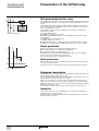
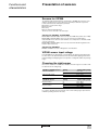
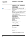
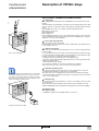
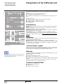
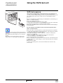
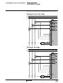
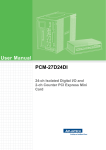
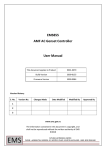
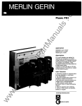
PCRED399008EN_Couv.FM Page 3 Lundi, 8. novembre 2004 11:41 11
0
0
0
0
0
User
manual
2004
Electrical network protection
VIP300
Contents
Functions and characteristics
Presentation of the VIP300 relay
2
Presentation of sensors
3
Description of VIP300 relays
4
Presentation of the VAP6 test unit
8
Using the VAP6 test unit
9
Technical characteristics
10
Installation and connection
Mounting
14
Connection
16
1
Functions and
characteristics
Presentation of the VIP300 relay
DE50967
Self-powered protection relay
Simplified wiring diagram.
The VIP300 relay is designed for use in power distribution systems. It may be used
to protect MV/LV transformers, incoming points of industrial installations or branch
feeders.
The VIP300 provides protection against phase-to-phase faults and earth faults. The
choice of tripping curves and multiple settings make is suitable for use in a wide
variety of discrimination schemes.
The VIP300 is a self-powered relay (supplied by current sensors) requiring no
auxiliary power supply.
It actuates a Mitop release.
The VIP300 is available in three models:
b VIP300LL and VIP300P, designed for use with RM6, SFset and Evolis 24 kV
circuit breakers
v VIP300LL: phase and earth protection
v VIP300P: phase protection only
b VIP300LH, designed for use with Ringmastercircuit breakers: phase and earth
protection with an equivalent time multiplier table on the front to convert settings.
DE10332
Phase protection
The phase protection has two separately adjustable thresholds:
b the low threshold may of the definite time or IDMT type
b the high threshold is of the definite time type.
The IDMT curves comply with standard IEC 60255-3. They are of the standard
inverse, very inverse and extremely inverse types.
The low threshold may also be used with the RI curve.
Earth protection
Earth fault protection is based on residual current measurements using the sum of
the sensor secondary currents.
Like phase protection, earth protection has two separately adjustable thresholds.
Phase and earth fault curves.
Equipment description
The VIP300 relay is mounted in an injected polycarbonate casing that protects them
against dripping water and dusty environments.
The front is protected by a transparent cover fitted with a sealing gasket. The cover
may be lead-sealed to protect access to the settings.
Rotary selector switches are used for setting. The phase and earth fault current
settings are set in amperes. This means that the graduations on the front must be
adapted to suit the sensor range used. This is done by fitting the appropriate setting
label when mounting the relay.
The connection is made on the back of the relay using fast-on type connectors.
Indication
Two indicators show the cause of tripping (phase or earth fault). The indication is
maintained even if relay power is cut.
Two LEDs (phase and earth) indicate that the low threshold has been overrun and
that the time delay is running.
2
Functions and
characteristics
Presentation of sensors
Sensors for VIP300
To obtain the indicated performance characteristics, VIP300 relays must be used
with the specified sensors. The relay/sensor assembly is defined to respect the
technical characteristics indicated, in particular:
b operation over the enitre range
b response time
b accuracy
b short-circuit thermal withstand.
The three sensors must be of the same type.
Sensors for VIP300LL and VIP300P
b CRa 200/1 and CRb 1250/1 sensors are used on RM6 units (models since 1998).
b CSa 200/1 and CSb 1250/1 sensors are used on SFset circuit breakers.
CSa and CSb sensors have the same number of secondary turns as the CRa et CRb
sensors respectively.
b CEa 200/1 and CEb 1250/1 sensors are used on 24 kV Evolis integrated circuit
breakers (lateral versions).
Sensors for VIP300LH
b 200/1 and 800/1 are used on Ringmaster circuit breakers.
VIP300 sensor input ratings
Each VIP 300 has two input ratings corresponding to two different operating ranges.
For this reason, the input transformers have an intermediate tapping point on their
primary winding. Each tapping point corresponds to a rating with a different operating
range.
Choosing the right sensor
Choose the sensor to be used and the VIP300 connection range in accordance with
the desired current setting range.
VIP300LL / VIP300P sensors
Rating
Current setting range
CRa, CSa, CEa 200/1
x1
10 A - 50 A
x4
40 A - 200 A
CRb, CSb, CEb, 1250/1
x1
63 A - 312 A
x4
250 A - 1250 A
VIP300LH sensors
Rating
Current setting range
Ringmaster 200/1
x2
20 A - 100 A
x4
40 A - 200 A
Ringmaster 800/1
x2
80 A - 400 A
x4
160 A - 800 A
For a given operating range, the bottom of the current setting range represents the
minimum operating current of the relay.
3
Description of VIP300 relays
Phase protection
1. phase overcurrent protection zone
2. threshold overrun indicator
3. phase trip indicator
4. phase current setting Is
5. choice of low threshold curve type
6. low threshold I>
7. low threshold time delay t>
8. multiplying factor (low threshold)
9. high threshold I>>
10. high threshold time delay t>>
DE50969
Functions and
characteristics
Earth protection
11. earth fault protection zone
12. threshold overrun indicator
13. earth trip indicator
14. earth current setting Ios
15. low threshold time delay to>
16. low threshold Io>
17. choice of low threshold curve type
18. multiplying factor (low threshold)
19. high threshold Io>>
20. high threshold time delay to>>
Other functions
a. setting label
b. sensor and range information
c. indicator reset
d. minimum operating current
e. VAP6 test plug
f. VIP300LL: tripping curves
VIP300LH: equivalent time multiplier table for conversions.
DE50970
VIP300LL/VIP300LH front panel.
VIP300P front panel.
4
Functions and
characteristics
Description of VIP300 relays
VIP300LL, VIP300LH and VIP300P phase
protection
DE10324
See also c: indicator reset button.
DE10325
Curve 1: phase setting V IDMT low threshold
b 1: phase protection setting zone
The phase protection settings are located in the top half of the front panel.
b 2: threshold overrun indicator
When the red indicator blinks, the phase protection low threshold time delay is
running. When this is the case, if the current does not decrease, the relay will trip.
For IDMT curves (SI, VI, EI), the LED lights up when the current is greater than 1.2
times the current setting Is.
For the IDMT curve (RI), it lights up when the current is greater than the Is setting.
For the definite time curve DT, it lights up when the low threshold is overrun.
b 3: trip indicator
It is normally black and turns yellow to indicate that the phase protection has given a
tripping order. It stays in the same status, even when the relay is no longer energized.
b 4: choice of current setting Is
The current setting range depends on the sensor and range used: the selector switch
graduations should be adapted to suit the sensor and range using the setting label.
b 5: choice of type of low threshold curve
v DT: definite time
v SI: inverse time
v VI: very inverse time
v EI: extremely inverse time
v RI: specific curve
v off: low threshold disabled.
b 6: choice of low threshold I>
The threshold is a multiple of the current setting. It is only active for definite time
thresholds (selector switch 5 set to DT).
If the tripping curve is selected with IDMT (selector switch 5 set to RI, SI, VI, EI), the
selector switch has no effect.
b 7: setting of low threshold time delay t>
If the tripping curve is of the definite time (DT) type, the selector switch sets the low
threshold time delay.
If the curve is of the IDMT type (RI, SI, VI, EI), the value displayed is the tripping time
for a phase current equal to 10 times the current setting.
b 8: low threshold time delay multiplying factor
In the x10 position, the time delay displayed on selector switch 7 is multiplied by 10.
b 9: setting of high threshold I>>
The high threshold is chosen as a multiple of the current setting.
In "off" position, the high threshold is disabled.
b 10: setting of high threshold time delay t>>
The time delay is set directly in seconds.
Phase protection setting
The numbers indicated on the curves opposite are those of the phase protection
setting switches (refer to the diagram of the front view).
Curve 2: phase setting V definite time low threshold
Set:
b current setting Is (4)
b type of low threshold I> curve (5)
v IDMT: RI, SI, VI, EI
v definite time: DT
b low threshold I> (6). This setting is only active if the low threshold curve chosen is
of the definite time DT type (curve 2). For the other choices, SI, VI, EI, RI (fig 1), the
selector switch is disabled.
b low threshold time delay t> (7) and (8)
b high threshold I>> (9)
b high threshold time delay t>> (10).
5
Functions and
characteristics
Description of VIP300 relays
VIP300LL and VIP300LH earth protection
The principle is the same as for phase protection.
The earth fault threshold overrun indicator only lights up if the
phase current is greater than the minimum operating current.
See also c: indicator reset button.
b 11: earth protection setting zone
The earth protection settings are located in the bottom half of the front panel.
b 12: threshold overrun indicator
When this indicator blinks, the earth protection low threshold time delay is running.
When this is the case, if the current does not decrease, the relay will trip.
for IDMT curves (SI, VI, EI), the LED lights up when the current is greater than 1.2
times the current setting Ios.
For the IDMT curve (RI), it lights up when the current is greater than the Ios setting.
For the definite time curve DT, it lights up when the low threshold is overrun.
b 13: trip indicator
It is normally black and turns yellow to indicate that the earth protection has given a
tripping order. It stays in the same status, even when the relay is no longer energized.
b 14: choice of current setting Ios
This is the maximum residual current that can flow in the system without the
protection being tripped.
The Ios current setting range depends on the sensor and range used: the selector
switch graduations should be adapted to suit the sensor and range using the setting
label.
b 15: setting of low threshold time delay to>
If the tripping curve is of the definite time (DT) type, the selector switch sets the low
threshold time delay
If the curve is of the IDMT type (RI, SI, VI, EI), the value displayed is the tripping time
for an earth current equal to 10 times the current setting.
b 16: choice of low threshold Io>
The threshold is a multiple of the current setting. It is only active for definite time
thresholds (selector switch 17 set to DT).
If the tripping curve is selected with IDMT (selector switch 17 set to RI, SI, VI, EI), the
selector switch has no effect.
b 17: choice of type of low threshold curve
v DT: definite time
v SI: inverse time
v VI: very inverse time
v EI: extremely inverse time
v RI: specific curve
v off: low threshold disabled.
b 18: low threshold time delay multiplying factor
In the x10 position, the time delay displayed on selector switch 15 is multiplied by 10.
b 19: setting of high threshold Io>>
The high threshold is chosen as a multiple of the current setting Ios.
In "off" position, the high threshold is disabled.
b 20: setting of high threshold time delay t>>
The time delay is set directly in seconds.
Earth protection setting
The principle is the same as for phase protection.
Set:
b current setting Ios (14)
b type of low threshold Io> (17)
v IDMT: RI, SI, VI, EI
v definite time: DT
b low threshold Io> (16). This threshold is only active if the low threshold curve
chosen is of the definite time DT type. For the other choices, SI, VI, EI, RI, the
selector switch is disabled.
b low threshold time delay to> (15) et (18)
b high threshold Io>> (19)
b high threshold time delay to>> (20)
Operation
The high and low thresholds operate separately.
The tripping order results from a "logical OR" between the two thresholds.
6
Functions and
characteristics
Description of VIP300 relays
Other VIP300LL, VIP300LH and VIP300P functions
DE50982
M
b a: setting label
The setting label should be fitted on the VIP300 when it is mounted on the circuit
breaker.
The label indicates the graduations of the phase current and earth protection setting
selector switches. It is inserted from the top, behind the transparent part of the front
panel.
Each VIP300 comes with a set of labels. Install the label that matches:
b the type of sensor used
b the VIP300 model
b the range used.
Each setting label matches a sensor and is printed on both sides for each of the two
ranges. The label may therefore be turned around if the VIP300 range is changed
during the service life of the installation.
b b: sensor and range indication
The text is printed on the setting label.
When the label is in position in the slot, the text is hidden by a non-transparent zone.
It is not visible to the user.
How to fit the setting label
DE50975
Minimum operating current: the VIP300 does not operate below
the minimum operating current level. As a result, if the earth
protections are set below the minimum operating current, they
will only take effect when there is phase current greater than or
equal to the minimum operating current.
b c: indicator reset button
The button is accessible when the transparent cover is closed. Pressing the button
has two results:
v it resets (black position) the two phase and earth trip indicators (when the relay is
no longer energized, it is still possible to reset the indicators for about 48 hours; after
that time, they may be reset after the VAP6 is plugged in)
v it lights up the two red LEDs (about 3 s). This indicates that:
- the relay is energized (the indicator lights up when the current is greater than the
minimum operating current)
- relay self-testing results are OK.
If one of the two conditions is not met, the indicators do not light up.
This function may be used to carry out a basic relay operation test.
b d: minimum operating current
The minimum operating current is the phase current required for the relay to be
energized and operational. It is printed on each setting label.
The value given on the setting label is the three-phase rms minimum operating
current. The minimum operating current always corresponds to the the lowest value
of the current setting range.
b e: VAP6 test plug
The test plug is exclusively designed for connection of the VAP6, used for fast and
easy relay testing.
The test may be carried out during normal operation of the installation since the
VAP6 and VIP300 provide the possibility of testing without circuit breaker tripping.
b f: tripping curves
v VIP300LL/VIP300P
v VIP300LH: equivalent time multiplier table for conversions.
Testing the VIP300 with the VAP6
7
Functions and
characteristics
Presentation of the VAP6 test unit
DE50916
The VAP6 is a portable unit that is connected to the VIP300 to carry out simplified
testing.
The test can be carried out in the following two cases:
b the VIP300 is already supplied by the sensors.
b the VIP300 is not supplied ; in this case, the VAP6 batteries supply power to the
relay.
The test consists of:
b initiating the VIP300 central processing unit self-test sequence
b injecting a stimulus to simulate a phase fault
b injecting a stimulus to simulate an earth fault
b checking tripping.
Push-buttons
b Battery test: if the batteries are OK, the "on" indicator lights up while the button is
pushed.
b Phase overcurrent: sends the phase protection test stimulus. The stimulus is
equivalent to 20 times the phase current setting Is.
b Earth fault: sends the earth protection test stimulus. The stimulus is equivalent to
20 times the earth fault current setting Ios.
b Trip inhibition: press the "trip inhibition" button if the VIP300 test should be
carried out without tripping of the circuit breaker. Circuit breaker tripping is disabled
while the 'trip inhibition" button is pressed, even if the tripping order results from a
real fault.
Indicators
b On: indicates that the batteries are operating. Also lights up when the battery test
is carried out by pressing "battery test".
b Test in progress: confirms sending of the test stimulus to the VIP300.
b Trip: used to test other relays in the VIP range. It should be ignored for the VIP300
test (it lights up for a short time when the VIP300 sends a tripping order, whether or
not the circuit breaker is inhibited).
VPA6 front panel
"external mitop" output
It may be used to connect an auxiliary mitop designed, for instance, to stop a stop
watch during operating tests. The mitop is triggered at the same time as the circuit
breaker mitop. It is not inhibited by pressing the "trip inhibition" button.
Batteries
The VAP6 is supplied by batteries. Therefore the parts of the
VIP300 that require AC current are not checked using this
method (input and supply circuits).
To conserve battery life, the batteries are normally off and automatically go on when
the VAP6 is connected to the VIP300.
They go on when:
b the "battery test" button is pressed
b the VAP6 is connected directly to a VIP3X or VIP5X relay
b the VAP6 is connected to the adapter cord designed for testing the VIP1X or VIP2X
relays.
To install or change the batteries, open the unit by removing the 4 screws on the
bottom. Always observe correct battery polarity (+/-).
Technical characteristics
b supply: 3 x 9 V 6LR61 batteries
b weight: 0.45 kg
b dimensions: 93 x 157 x 45 mm.
8
Functions and
characteristics
Using the VAP6 test unit
DE50992
VAP6 test sequence
The test may be carried out with or without current in the sensors. During the test
operations, all the VIP300 settings are effective; the relay should perform in
accordance with the settings. During the test, the relay remains operational and will
give a tripping order in the event of a fault, unless the "trip inhibition" button is
pressed.
b Connect the VAP6 to the "VAP6 test plug". The VAP6 batteries automatically go on
and the "on" indicator lights up.
b Press the VIP300 "reset" button:
v if the two "trip" indicators were yellow, they go black
v the two red I> and Io> indicators of the VIP300 light up for about 3s to indicate that
the central processing unit has correctly performed self-testing.
b Press the "trip inhibition" button if the test should be carried out without tripping of
the circuit breaker.
Be sure to keep the "trip inhibition" button pressed throughout the time it
takes to send the stimulus.
If the "phase overcurrent" button is held down after tripping, the
VIP300 starts the time delay/tripping cycle again; this is normal.
In that case:
b the VAP6 red "trip" indicator lights up for a short time after
each trip
b depending on the time delay setting, the VIP300 red "I>"
indicator may be off or blink rapidly in an irregular manner.
b Press the "phase overcurrent" button to send the phase protection test stimulus:
v continue pressing the button throughout the duration of the stimulus (the stimulus
represents about 20 times the current setting Is)
v the VAP6 "test in progress" indicator lights up to confirm the sending of the
stimulus to the VIP300 relay
v the red "I>" indicator of the VIP300 blinks during the time delay period
v then the VIP300 phase "trip" indicator turns yellow
v the circuit breaker trips if it is not inhibited.
b Press "earth fault" to test operation of the earth protection. The stimulus injected
is equal to 20 times the current setting Ios. Use the same procedure as for the phase
protection test.
b Disconnect the VAP6.
In order to save battery power, do not leave the VAP6 connected to the relay
unnecessarily
.
9
Functions and
characteristics
Technical characteristics
Phase protection
Accuracy
Low threshold I>
±5 % or 0/+2 A
(1)
Low threshold time delay t>definite time
±2 % or ±20 ms
(2) (8)
class 5, IEC 60255-3 or 0/+20 ms
(2) (8)
IDMT
±5 %
High threshold I>>
High threshold time delay t>>
±2 % or ±20 ms
Drop-out/pick-up %
95 %
Storage time
20 ms
(2)
Earth protection
Low threshold Io>
±5 % or 0/+2 A
Low threshold time delay to>definite time
±2 % or ±20 ms
IDMT
High threshold Io>>
classe 5, IEC 60255-3 ou 0/+ 25 ms
±2 % or ±20 ms
Drop-out/pick-up %
95 %
Storage time
20 ms
Continuous thermal withstand
Short-time thermal withstand
(2) (8)
Value
240 A
with CRa, CSa or CEa sensor
1500 A
with CRb, CSb or CEb sensor
240 A
with RMR 200/1 sensor
960 A
with RMR 800/1 sensor
25 kA / 1 s
with CRa, CRb, RMR 800/1,
CSa, CEa, CSb or CEb sensor
25 kA / 1 s
with RMR 200/1 sensor on range x2
20 kA / 1 s
with RMR 200/1 sensor on range x4
Operating frequency
50 Hz ±10 %, 60 Hz ±10 %
Operating temperature
–25 °C to +70 °C
Storage temperature
–40 °C to +85 °C
Weight
1.7 kg
Minimum operating current
VIP300LL/VIP300P + CRa, CSa or CEa sensor
VIP300LL/VIP300P + CRb, CSb or CEb sensor
VIP300LH + RMR 200/1 sensor
VIP300LH + RMR 800/1 sensor
Climatic withstand
(2) (5) (8)
±5 %
High threshold time delay to>>
General characteristics
(3) (4) (5)
Range
Value
x1
10 A
x4
40 A
x1
63 A
x4
250 A
x1
20 A
x2
40 A
x1
80 A
x2
160 A
Standard
(7)
Severity
Low temperature operation
IEC 60068-2-1
–25 °C, 16 h
Low temperature storage
IEC 60068-2-1
–40 °C, 96 h
High temperature operation
IEC 60068-2-2
+70 °C, 16 h
High temperature storage
IEC 60068-2-2
+85 °C, 96 h
Fast changes in temperature
IEC 60068-2-14
–25 °C à +70 °C, 5 cycles
Operation in damp heat
IEC 60068-2-3
56 days, 93 % HR
Salt spray
IEC 60068-2-52
severity 1
10
Functions and
characteristics
Technical characteristics
Mecanical withstand
Standard
Severity
Vibrations
IEC 60255-21-1
class 2
Shocks and bumps
IEC 60255-21-2
class 2
Earthquakes
IEC 60255-21-3
class 2
Enclosure degree of protection
EN 60529
IP54 (cover closed)
Fire resistance
IEC 60695-2-1
650 °C
Standard
Severity
Electrical withstand
Sensor input isolation
IEC 60255-5
2 kV rms, 50 Hz, 1 mn
1.2/50 µs impulse voltage
IEC 60255-5
5 kV (6)
Oscillatory waves - 1 MHz burst
IEC 60255-22-1
2.5 kV cm (6)
Fast transient bursts
IEC 60255-22-4
4 kV common and diff. modes, 5 kHz burst (6)
1.2/50(8-20 µs) hybrid wave
IEC 61000-4-5
2 kV, 42 Ω (6)
1 kV dm
Electrostatic discharge
IEC 60255-22-2
8 kV in air, 6 kV on contact
HF electromagnetic field
IEC 60255-22-3
30 V/m not modulated, 27 to 1000 MHz
EN 50082-2
10 V/m modulated, ampl., 80 to 1000 MHz
EN 50082-2
10 V/m modulated, impuls., 900 MHz
(1) Value given for three-phase VIP300 power supply. For single-phase operation, the accuracy range is ±10% or 0/+5A.
For the low threshold, this does not generally represent a real operating situation. However, it may occur during injection testing carried out with a single-phase
supply.
The error is mainly due to the non-linearity of the sensors and VIP300 input transformers for low currents; the inaccuracy is accentuated when the relay is only
supplied by one phase.
(2) The accuracy is indicated for a fault (sinusoidal current) that occurs when the VIP300 is already supplied by the current flowing through the circuit breaker. In
the event of closing on a fault, the tripping time may be increased by:
b +30 ms at 1.5 Is
b +20 ms from 2 Is to 10 Is
b +10 ms above 10 Is.
(3) Generally speaking, the accuracy ranges of earth protection times and thresholds are indicated for a VIP300 supplied by a current that is greater than or equal
to the minimum operating current. The measurement of a threshold for earth protection with a single-phase supply is therefore not significant if the threshold is lower
than the minimum operating current.
(4) Value given for three-phase VIP300 supply. For single-phase testing, the accuracy is ±10% or 0/+5A.
For the low threshold, this may occur when the earth protection is tested with a single-phase supply and no supply by the other phases.
(5) Under the following specific conditions:
b VIP300LL
b with CRa sensor
b wired to x1 range
b if Ios < 8 A
b if three-phase current < 20 A
the threshold and time delay characteristics are:
b low threshold: ±10 % or 0/+4 A
b class not specified.
(6) Not applicable to test plug.
(7) Accuracy ±10 % or ±1.5 A.
The value indicates the guaranteed minimum operating current for three-phase operation.
(8) The tripping times indicated do not include the mitop response time that depends on the mechanical load (for no load, its tripping time is less than 5 ms).
11
Technical characteristics
IDMT tripping curves
Functions and
characteristics
The curves in this chapter indicate the IDMT low threshold tripping times for the 16
t> (or to>) time delay settings.
The phase protection and earth protection curves are the same.
The numbers indicated to the right of the curves represent the settings on the t> (or
to>) time delay selector switch.
DE51247-SI
SI curve
DE51248-VI
VI curve
12
Technical characteristics
IDMT tripping curves
Functions and
characteristics
DE51249-EI
EI curve
RI curve
DE51250-RI
T(s)
10
1
0,1
0,01
1
10
100
I/Is
13
Installation and connection Mounting
Dimensions
DE10328
The VIP300 is designed for flush-mounting in rectangular cut-outs in sheet-metal
panels with a maximum thickness of 3 mm.
0.3
(*) The 4 holes are required only when
mounting the VIP on SFset or Evolis
24 kV circuit breakers.
DE10337
VIP300 mounting dimensions.
DE50981
Mounting the VIP300
The latch may be put into the vertical position by loosening
each of the screws (V) before tightening them.
b Insert the VIP300 in the cut-out and correctly position the two bottom pins (E) of
the casing on the edge of the panel cut-out.
b Tighten the screws (V) on the two mounting lugs accessible via the front after
opening the transparent cover.
b After tightening, make sure that the latch (N) of each lock (visible on the rear face)
is in the vertical position, pressing against the panel.
b The hole (P) may be used to lead-seal the relay after the setting label has been
fitted and the settings made
14
Installation and connection Mounting
Fitting the setting label
b Slide the setting label into position behind the transparent part of the front face.
b Make sure that the indications at the top of the label (M) match:
v the sensor used (sensor)
v the VIP300 model
v the range used (range).
This information is hidden when the label is in position.
b Make sure that it is pushed right to the bottom of the slot.
b To remove the label, use the hole in the top, if necessary with the help of the tip of
a pencil or a screwdriver.
DE50982
M
Choosing the right setting label
recto
verso
recto
verso
x1 range
x4 range
x1 range
x4 range
DE50984
Setting label for VIP300LL and VIP300P
with CRb, CSb or CEb sensors
DE50983
Setting label for VIP300LL and VIP300P
with CRa, CSa or CEa sensors
recto
verso
recto
verso
x2 range
x4 range
x2 range
x4 range
DE50986
Setting label for VIP300LH with
Ringmaster 800/1 sensors
DE50985
Setting label for VIP300LH with
Ringmaster 200/1 sensors
15
Installation and connection Connection
VIP300LL and VIP300LH models
Connections are made to the back of the VIP300 via 6.35 mm fast-on connectors.
DE50976
Wiring to x1 (or x2) range
DE50977
Wiring to x4 range
16
Installation and connection Connection
VIP300P model
Connections are made to the back of the VIP300 via 6.35 mm fast-on connectors.
DE50978
Wiring to x1 (or x2) range
DE50979
Wiring to x4 range
17
Notes
18
Notes
19
Notes
20
PCRED399008EN - 51311871EN/A0 - © 2004 - Schneider Electric - All right
PCRED399008EN_Couv.FM Page 2 Lundi, 8. novembre 2004 11:41 11
Schneider Electric Industries SAS
Postal address:
Communication Distribution Electrique
38050 Grenoble cedex 9 - France
Tel : +33 (0)4 76 57 60 60
As standards, specifications and designs change from time to time, please ask for confirmation
of the information given in this publication.
This document has been printed
on ecological paper.
http://www.schneider-electric.com
Design: Ameg
Publication: Schneider Electric
Printed:
ART.20499
11-2004