1
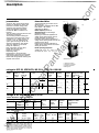
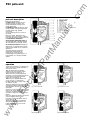
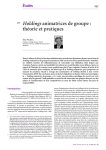
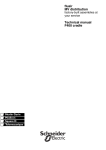
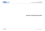
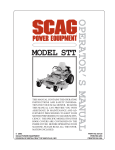
.c om ww w .E lec tri ca lP ar tM an ua ls Fluarc FG1 application Substation up to 15.5kV Metalclad up to 13.8kV Retrofit up to 17.5kV description FG1 circuit-breakers are applied for switching and protection on medium voltage networks; FG1 breakers are using rotating arch technology with SF6 medium for insulation and breaking. T hree segregated phases are encapsulated into a single epoxy bottle. Pressure of inside SF6 gas is 2.5 bars (relative pressure). FG1 bottle is a "sealed for life pressure system". main features extremely compact for reduced space and easy adaptation to switchgear • low maintenance • because of sealed bottle, breaker is not affected by hostile environments • soft interruption reduces transient over voltages due to restrikes/prestrikes • option pressure switch allows permanent check of dielectric/breaking medium • ideal for capacitor bank switching • comes in fixed version as standard; drawout on request • mastering electrical power MERLIN GERIN pole cross section breaking principle ANSI ratings C 37-06 upper current terminal absorbent material insulating enclosure attachment solenoid fixed main contact fixed arcing contact upper arcing ring lower arcing ring moving main contact moving arcing contact insulating rod shaft with sealing device lower current terminal lP outdoor Fluarc FG1 15.20 tM 1 2 3 4 5 6 7 8 9 10 11 12 13 14 Rotation of the arc between the circular arcing contacts is caused by an intense electromagnetic field. T his field is produced by a solenoid through which the current to be interrupted flows at the moment of opening. ar SF6 is an uninflammable, colorless, odorless, non-toxic gas, five times heavier than air. Its dielectric strength is much higher than air at atmospheric pressure. T hanks to SF6 gas qualities and to rotating arc principles. • when switching motors and tranformers, overvoltages are very low: no successive prestrikes/restrikes • excellent capability for capacitor switching an ua ls FG1 .c om sulfur hexafluoride gas properties voltage range factor (K) rated insulation impulse 1.2/50us level 1 mn 60Hz symi.C. at rated voltage continuous ampere rating closing and latching capability 15.5kV 1 110kVcrest 50kV 20kA 600-1200A 54kAcrest ca rated maximum voltage indoor Fluarc FG1 500- 13.8kV/500MVA class (K) rated insulation impulse 1.2/50 us level 1 mn 60Hz symi.C. at rated max kV continuous ampere rating short time rating (3 sec) closing and latching capability 1.3 95kVcrest 36kV 18kA 600-1200A 23kA 37kArms tri rated voltage range factor top view lec dimensions (inches) front view side view 22.6 f .E 11.3 .l c::ICI D�o 0 23.3 w approx. weight: 265 pounds ww MERLIN GERIN, INC. Suite 150 5000 Highlands Parkway Smyrna, Georgia 30082 Tel: 404-432-2744 Telex: 544018 Fax: 404-432-9179 FG1 US 288 As standards specifications and designs change from time to , time, please ask for confirmation of the information given ic this publication. Design by F. Becheret 3/88 Sir Speedy Printing Center .c om ar tM an ua ls Fluarc FG1 3 to 15 kV ww w .E lec tri ca lP fixed FG1 withdrawable FG1 mastering electrical power .c om description -" The Fluarc FG1 type three-pole circuit breakers are designed for control and protection of medium voltage public distribution and industrial networks. These circuit-breakers use sulphur hexafluoride SF& for insulation and breaking. They are made up of three pole-units and an operating mechanism. The insulating enclosure housing the active parts of these pole-units is filled with SF6 gas at a relative pressure of 2.5 bars. It is of the sealed pressure system type according to the IEC 56 definition, appendix EE, 1987 edition. Their main qualities are as follows: • long life expectancy, • no maintenance of active parts, • high electrical endurance, • very low surge level, • operating safety, • insensitivity to the environment, • possibility of permanent circuit-breaker state control (optional pressure switch), • well-suited to high-speed reclosing and capacitor bank control. The characteristics given below are as defined by the: IEC regulations, publication 56 and 694, UTE volume C 64 1 00/101 , VDE 0670 and BS 531 1. 3 fixed FG1 2 an Rated frequency: 50-60 Hz. Operating times at rated voltage (indicative values): • opening time between application of voltage to the opening device and arc contact separation: 45 to 65 ms; • breaking time between application of voltage- to the opening device and final arc extinction: 60 to 80 ms; • closing time between application of voltage to the closing device and contact closing: 60 to 90 ms. ua ls presentation characteristics ar tM Rated operating sequence: standard: 0- 3 mn - CO - 3 mn - CO on request: 0 - 0.3 s - CO - 15 s - CO withdrawable FG 1 1 Three-pole enclosure 2 Auxiliaries LV connector Operating mechanism 4 Racking lever lP 3 making capacity (2) 3-second capacitor breaking withstand capacity for a rated current current of (A) A rms kA peak kA rms 630 A 1250 A 630-1250 50 73 20 25 (3) 440 440 875 875 a b 630-1 250 50 73-66-63 20 25 (3) 440 440 875 875 c d 630-1 250 50 20 440 875 e ratings to IEC 56, VDE 0670, BS 5311, UTE C 64 100/101 kV kV peak kV rms kA 7.2 60 20 kV 3 to 7.2 75 tri 20 29 ca rated insulation level impulse (1) 1 mn 50-60Hz 1.2/50 J.LS 12 KV 7.2 to 10 28 95 38 11 20 26.2 20 29 continuous current index 12 20 25 kV 13.8 to 15 lec 15 I rated rated breaking capacity at U (kV) rated voltage 20 ratings to US standards ANSI C37-06 outdoor DFE Fluarc fixed circuit-breaker rated voltage K factor U maxi = kV U mini 1 15.5 breaking capacity lsc rated insulation level .E max. voltage impulse (1 ) 1.2/501-'s 1 mn 60Hz kV peak kV rms 110 50 kA at rated kV rated continuous current at 60Hz 3-second withstand current A kA rms 20 600-1200 20 closing and latching capability 2.7 times rated short-circuit current index 54 9 kA peak w Fluarc indoor circuit-breaker rated voltage Class (kV) / MVA 1 500 ww kV 13.8 Mini 11.5 U maxi --U mini / factor K / Maxi 1 1.3 1 15 (1) For installation in cubicles, the dielectric withstand is the responsibility of the cubicle designer. Merlin Gerin can provide recommandations upon specific request. When the circuit-breaker is supplied separately, in either the fixed or draw-out version, the insulation level rating is 75 kV (peak). (2) The making capacity corresponds to 2.5 times the breaking capacity at rated voltage. 1.,'\ 1"\� l"'n I,A i,.. rated insulation level impulse(1) 1 m n 1.2/50 J.LS 60 Hz kV peak kV rms / 95 1 36 3-second breaking capacity rated continuous withstand lsc current kV maxi current kV mini at 60Hz A kA kA kA rms closing and latching index capability 1.6 lsc (U mini.) 23 37 / 118 600-1200 23 kA rms I Rated supply voltages D .C.: 24-48-60-110-125-220 V A.C.: 110-127-220 V D .C.: • 1 coil • 4 • 1 coil • 5 6 7 8 9 closing release 120 to 250 W 70 W 180 to 350 VA 100 VA • • 2 coil • • 2 coil 2 coil • 1 coil 16 17 • 2 coil • 1 coil 2 coil 1 coil • 2 coil • 1 coil • • • • 10 11 12 13 14 1 coil 2 coil (3) Rated current: • • 1 coil • • • 2 coil • Consumptions at rated U single-coil shunt undervoltage single-coil overcurrent Self-current MITOP: D .C. w 70 15 of auxiliary contacts 10 A Breaking capacity: :::; in D . C.: 3 A at 110 V or 220 V o in A.C. at 0.3 pf: 10 A at 220 V • release type Auxiliary contacts Fluarc FG1 incorporates: • 5 auxiliary contacts if manually operated: o 1 used for the closing release c 1 used for the opening shunt trip release o 3 contacts remain available for customer's use • 14 auxiliary contacts if electrically operated: o 2 used for the electrical operating mechanism o 1 used for the opening shunt trip release o 11 contacts remain available for customer's use. Characteristics • A.C. VA 100 75 120 1 VA Options • 9 additional auxiliary contacts with manually-charged mechanisms, • open-position locking facility by Ronis ELS 11A key-lock (lock not supplied), • a closing contact pressure switch (SP) for indication of possible pressure drop. • a STATIMAX protection device without auxiliary power supply, with MITOP release, • "operating mechanism charged" indication contact (M3), • green-red 0-C indicator instead of standard green-white. (1) Withdrawable circuit·breaker with undervoltage release always has automatic discharging of the operating mechanism. (2) Overcurrent release power supply: 2 A - 5 A. (3) The MITOP release includes a low consumption bi-stable electromagnet designed to receive a low power order from the Statimax protection system ensuring protection without the use of an auxiliary source (see leaflet AC 42). lec tri ca Opening Manual opening by mechanical action via a pushbutton on the front panel. Electrical opening via indirect releases. Several types of indirect releases can be fitted. The 17 possible combinations are set out in the table opposite. • Mitop ua ls • 3 ar in in A.C.: 2 lP Consumptions at rated U auxiliary devices overundervoltage(1) current (2) 1 coil 1 coil • 15 Closing Manual closing by mechanical action via a pushbutton on the front panel. Electrical closing by a closing release (YF) and anti-pumping relay (KN). charging motor shunt trip an The Fluarc circuit-breaker is equipped with a GMh type spring stored-energy operating mechanism for fast opening and closing independent of operator action. It is equipped with either a manual or an electrical operating mechanism. These two systems comprise: • an operations counter; • a position indicator (ON/OFF). The springs are charged electrically, or manually by a removable lever in front in the event of auxiliary power failure. The electrical spring charging system includes a motor (M), automatically recharging the operating mechanism as soon as the breaker is closed (recharging time < 15 s), Release type no tM operating mechanism .c om operating mechanism and auxiliary devices .E Electrical operating mechanism wiring diagram ww w 2 3 4 5 Always supplied: Options: M YF M1-M2 Y01-Y02 YM YX YD QF KN spring charging motor closing release end-of-charging switch auxiliary contacts i i· ay . � ��� r����� �:! M3 GMh electrically charged operating mechanism shunt trip release undervoltage release overcurrent release "MITOP" release operating mechanism charged indication contact 1 2 3 4 5 closing and opening release latching unit closing springs frame spring charging motor .c om dimensions and weights fixed FG1 Optional: The fixed FG1 is furnished with the operating mechanism and the auxiliary devices mentioned in page 3. It is delivered for connection with busbars. connection terminals "P" a male and female LV 36 pin connection comprising a fixed connector on the circuit-breaker and a socket equipped with a 2 m conductor, • supporting frame. • 592 lP ar tM an J ua ls fixed unit •removable loading lever travel ca Weight: 120 kg �--- 6284 ---� 27 57 107 -j--180 + 150 �-r--137 lec 27 tri unit mounted on a support frame 963 1163 w or .E �c ! J j j00� ww ����:_;i --- --608;:�;:�;}� �� -- 644---1- • The units mounted on a support frame may take two positions Frame weiaht: 15 ka The support frame is fitted with rollers to make handling and installing the circuit breaker easy. A nchoring to the ground is possible by means of fixing lugs provided on the frame. description � position 2: o position 3: the lever unlocks the system and allows withdrawal of the breaker from the cubicle. I t also provides a stop motion action when the breaker is presented into the cubicle. Options for withdrawable unit: an • a female 36 pin LV connector with a 2 m conductor, • automatic discharging of the operating mechanism beyond the "test" or "disconnected" position (see note 1 page 3), • racking lock-out system preventing breaker insertion if the LV cable is not connected, • auxiliary contact indicating the breaker is secured in "service" position (SQ). • drawn-in /-out interlocking (keylock or padlock). position 1 : ar tM Circuit-breaker set in "service" or "test" position or disconnected outside of cubicle. For circuit-breaker operating (opening-closing), the lever must be set in position 1. dimensions and weights • front view withdrawal travel ww w .E FG1 lec tri ca lP 630- 1250 A withdrawable Weight: 140 kg a b c d ua ls the lever unlocks the system and allows moving the breaker from the "service" position to the "test" position, and inversely. The breaker must be opened before going into position 2. The withdrawable version of the Fluarc FG1 circuit-breaker is designed to facilitate installation and maintenance and to ensure upstream and downstream positive isolation indication. The unit is equipped with: • the operating mechanism and auxiliary devices mentioned on page 3, • a frame earthing contact, • a guide rail at the bottom (c), • a mechanical system to secure the breaker in "service" or "disconnected" position. The circuit-breaker is operated by a removable racking lever (d) on the front plate which can be set in 3 positions: L' .c om withdrawable FG1 = removable charging lever LV connector guide rail removable 3-position racking lever FG1 circuit-breaker installed in a F100 cubicle. pole-unit description 4 5 6 7 8 9 ������----¥*+--10 '-------.;S+;. 11 ,����-+�+r-1 --- 2 5 6 7 8 9 upper current terminal adsorbent material insulating enclosure attachment arc-quenching coil fixed main contact fixed arcing contact upper arcing ring lower arcing ring moving main arcing contact (tilting blade) moving arcing contact insulating rod shaft with sealing device rod lower current terminal. ua ls 4 10 11 12 13 14 15 an to the moving contacts, including the shaft 13 which activates the rods 12 and 14, lP ar tM An insulating enclosure 3 encloses all active parts. It is provided with a sealing system highly reliable for any number of operations. The filling pressure and breaker performance characteristics are maintained for at least 20 years, corresponding to the operating life of a circuit-breaker on a normally disturbed network. tri ca operation arcing contacts, it is magnetically 3 3 • a transmission mechanism conveying the mechanical energy The FG1 circuit-breaker is a magnetic unit which uses the arc rotating technique to interrupt the current. • A t the beginning of the opening operation, the main contacts and the arcing contacts are closed (fig. 1). • The main circuit is disconnected by separation of the tilting blades 10 and the current flows via the arcing contacts, which are still closed (fig. 2). • When the arc appears between the 1 2 2 Each pole-unit consists of: • a main circuit including the fixed contact 6 and the self-wiping, self compensated blades making up the moving contact 1 0, • a breaking circuit including the fixed arcing contact 7, moving arcing contact, two fixed arcing rings, upper 8, and lower9. A n arc-quenching coil 5 is in series in this circuit, • the main circuit, designed for the continuous flow of the current, is distinct from the breaking circuit subjected to the arc, .c om FG 1 pole-unit lec transferred between the arcing rings under the effect of the loop. D uring its passage the arc inserts the arc quenching coil which produces a magnetic field dependent upon the current to be interrupted. The arc is put into rapid rotation under the effect of the original electromagnetic force. The arc is thus cooled by forced convection through the movement of this rotation. D ue to the phase shift between the current and the magnetic field, this force continues to have a significant value at current zero (fig. 3). • Towards current zero, the dielectric strength between the contacts is very rapidly recovered due to the intrinsic qualities of SF6 (fig. 4) Fig. 2 opened main contacts Fig. 3 arcing time Fig. 4 opened circuit-breaker ww w .E Fig.1 closed circuit-breaker Advantages of the Fluarc FG Permanent control of the circuit breaker state The Fluarc FG1 is a modern circuit breaker making use of the rotating arc technique; it offers ideal arc cooling by forced convection, resulting in the following advantages: Possibility of adding a pressure controlling device to the switchgear. ua ls sulphur hexafluoride gas (SF6) properties Long life an This quality results from: • high product reliability, • very low wear of the active parts which require no maintenance, • the excellent enclosure sealing. These units need no complementary filling. Mechanical endurances SF6 is "the" breaking gas, combining the best properties: • high capacity for carrying the heat produced by the arc. The latter is strongly cooled by convection during the arcing period. • high radial thermal conduction and high electron captation capacity. When Electrical endurance The long life of the Fluarc is due to the negligible degeneration of the gas and to the low wear of the contacts. The energy dissipated in the arc is low due to: • the intrinsic properties of the gas, • the short arc length, • the very short arcing time. Wear of the arcing contacts can be checked, without opening the poles, by means of a wear indicator. The unit is capable of breaking all load and short-circuit currents for a period of 20 years, even in the case of frequent operation, and requires no maintenance of the active parts. ww w .E lec tri ca the current passes through zero, the arc is extinguished by the combination of these two phenomena: u SF6 permits rapid heat exchange from the centre of the arc towards the exterior, CJ fluorine atoms, which are highly electronegative, act as veritable "traps" for electrons. Since it is electrons which are mainly responsible for electric conduction in the gas, the gap between the contacts recovers its initial dielectric strength through this electron capture phenomenon at zero current. • the decomposition of the SF6 molecule Is reversible. The same mass of gas is therefore always available, making the device self-sustained throughout its operating life. tM breaking gas ar very stable, gas, five times heavier than air. Its dielectric strength is much higher than that of air at atmospheric pressure. uninflammable, The operating energy is reduced by using the natural expansion of the hot gases during breaking. The operating mechanism is the standard GMh-type and benefits from over 20 years of experience. The Fluarc circuit-breaker is able to carry out 10,000 operations without any parts being replaced. The periodic lubrication of the operating mechanism is recommended and depends on the environment and operation. lP SF6 is an non toxic .c om Fluarc technology Low switching surges The intrinsic properties of the gas and the soft break resulting from this technology means that the switching surges are very low. Concerning motor start-up, the unit provokes no multiple preignitions nor multiple reignitions which could damage the insulation between coil turns. Operating safety The Fluarc operates at low pressure with a relative pressure of 2.5 bars. A slight pressure rise occurs between the arcing rings only during the arcing period. Insensitivity to external coNditions The Fluarc pole-unit provides a completely insulated system. I ts is a hermetically sealed enclosure filled with SF6 gas in which are housed the following essential parts: • the breaking chamber, • the insulating rod which activates the moving contacts, • the electrical connection between the moving contact and the corresponding fixed terminal. The Fluarc pole-unit is therefore a Gaseous Insulated System (G.I.S.) date: . . I ...I order no: Name of project ....... . Name of client . Language for user manual . Requested service voltage .................... kV kA A . Short-circuit current at requested service voltage . Rated operating current Frequency ............... Insulation level: • Power frequency 1 mn .. kV kV Impulse 1.2 /501'-s .. Operating sequence: standard: 0- 3 mn - CO - 3 mn - CO. . .0 on request: 0- 0.3 s - CO- 15 s - CO . . . 0 • • Standards I EC . . . . . . ......... 0 ANSI . .. . . . . . . . . . . . . . . . 0 . . . . . installation and application characteristics . . . . . . . . . . ... . . . Fixed unit........ ................... 0 Withdrawable unit MG Fluair eqt.. 0 other equipment . . . 0 Merin Gerin incomplete panel I basic housing I compartment (separate form to be filled). . . . . . . . . . .. . . . . . . . . . . . . . . . .............. 0 ........... 0 Outdoor installation (DFE).... . . . . . . . . . . Qty L _'i ____ tM . . an • Hz . ua ls network characteristic s .c om order form for Fluarc FG 1 circuit-breakers ............ 0 . . . ........ Manual operating mechanism . Electrical operating mechanism . . .. . . . . . . 0 . . . . . . . . . . . . . . . . . . . . . . . . . ar . Common auxiliary devices (fixed and withdrawable units) Charging motor (M) . . . . . . . . . . . L.___l V 0 Closing release (YF) . . L___j V 0 Opening release (shunt trip release) L.__j V 0 Other opening releases.................... . . . . . . . D C, or 0 D C, or 0 D C, or 0 . . . · · · · · · · · · 0 . ca Common options (see page 3) A C L.___l Hz A C L___j Hz A C L__l Hz lP . additional auxiliary contacts with manually-charged mechanisms . . 0 Open-position breaker locking facility (lock not included) . . . . . ......... 0 0 Lock for above locking device Ronis ELS 1 1A . . . . . . . . ... .. .. Pressure switch (SP). . . . . . . . . . . . . . . . . . . . . . . . . . . . . . . . . . . . . . . . . .0 STA TIMAX system with MI TOP . . . . . . . . . . . . 0 9 . tri . . . . . . . . . . . . . . . lec Operating mechanisms charged indication contact (M3) O.C. green-red mech. indicator (instead of green-white) . . . . . . . Options for fixed unit (see page 4) Male and female 36 pin LV connector with a 2 m conductor. Supporting frame . . . . . . . . . . . . . . . .E . . . . . . . . . . . . . . . . Options for withdrawable unit (see page 5) A female 36 pin LV connector with a 2 m conductor A utomatic discharging of the operating mechanism Racking lock-out on LV connector . . . .. . . . . . . . . . . . . . w . . . . . . . . . . . . . .. . . . . . . . . . . . . . . . . . . . . . . . . . . . . . . . . . . . "Breaker secured in position" contact (SO) . . .. . D rawn-in /out interlocking (keylock or padlock) . . Key for above interlock . . . . . . .. . ... . .. . . .. .. . . .. .. . . . . . . . . ............ . 0 ........ ... 0 . . . . . . . . . . . . . . . D 0 . . . .0 .0 . . . . 0 . . . . . . . . . . . . . . . . . .. . . . . . ..... 0 . 0 . ......... 0 . . . . . . . . . . . . . . ww Special conditions. MERLIN GERIN 38050 Grenoble cedex France tel. 76 57 60 60- As standards, specifications and designs change from time to time, please ask for confirmation of the information given in this publication.