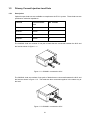
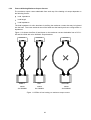
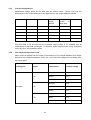
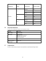
1
OPERATING AND MAINTENANCE MANUAL
Product:
Primary Current Injection System
Type:
PCU1-SP mk2
PCU1-LT mk2
DESIGNED AND MANUFACTURED BY:
T & R Test Equipment Limited
15-16 Woodbridge Meadows, Guildford, Surrey, GU1 1BJ, United Kingdom
Telephone: 01483 207428
e-mail:
[email protected]
Fax.:
01483 511229
Web:
www.trtest.com
1
GENERAL SAFETY STATEMENT
WARNING
The following safety precautions should be reviewed to avoid injury to the user and damage to the
product (and other products connected to it). To avoid potential hazards only use this product as
specified.
Only suitably qualified personnel should use this equipment. Servicing of this product
should only be carried out by suitably qualified service personnel.
To Avoid Fire Hazards and Personal Injury
Use the correct power supply lead. Only use a suitably rated and approved power supply lead for
the country of use.
Ensure that systems that the unit is to be connected to are isolated from the supply and earthed.
Do not connect and disconnect leads whilst outputs are switched on. Breaking the output circuit
with current flowing may cause potentially fatal arcing.
Ensure that the product is grounded. To avoid electric shock it is essential that the grounding
conductor is connected to the earth ground. An additional earth terminal is provided on the unit that
should be connected to a local earth. Ensure that the unit is properly grounded before making any
connections to inputs or outputs.
Terminal ratings must be observed to prevent fire hazards and risk of injury to the operator. Consult
the product manual for ratings information before making connections to any terminal.
It is ESSENTIAL to consult the product manual for rating information before making any connection
to a terminal or terminal group marked with a warning triangle.
Only use fuses of a type and rating specified for this product.
Do not operate the unit out of its case or with any covers or panels removed.
Do not touch exposed connections and components when power is present.
Do not operate the product if any damage is suspected.
personnel to be checked.
Refer the unit to qualified service
Do not operate the unit in wet or damp conditions
Do not operate the unit in an explosive atmosphere
The PCU1 systems have a very high output current (up to 10kA), and therefore generate large
magnetic fields around the output leads and loading transformer. Care must be taken in siting the
unit next to items sensitive to magnetic fields (such as computer monitors and other sensitive
equipment).
Warnings from cardiac pacemaker manufacturers state that strong magnetic fields may affect
operation. Any high current unit such as the PCU1 should therefore not be operated by, or in the
vicinity of persons fitted with cardiac pacemakers or any other electronic or electrical medical
implants.
If any further queries occur regarding the usage and maintenance of the equipment
detailed in this manual, please refer these to the supplier of the equipment in the first case
or to the manufacturer, T & R Test Equipment Limited.
2
SAFETY TERMS AND SYMBOLS
The following safety symbols appear on the equipment:
CAUTION/WARNING – Refer to manual
HOT – Refer to manual
Mains off
Mains on
The following safety symbols appear in this manual:
CAUTION
This action or procedure may be dangerous if not carried
out correctly, and may cause damage to the equipment or
connected equipment.
WARNING
This action or procedure may cause injury or death to the
operator or other personnel if not carried out correctly using
applicable safety procedures.
HOT
Parts of the unit may become hot during use, particularly
when operating at high currents
3
CONTENTS
1.
DESCRIPTION OF EQUIPMENT
1.1
Control Unit Front Panel Layout and Functions
10
1.2
Loading Unit Front Panel Layout
12
1.2.1
NLU2000 & NLU5000
12
1.2.2
NLU200
13
1.3
Electrical Specification
14
1.3.1
Supply Requirements
14
1.3.2
Loading Unit Outputs
15
1.3.3
Secondary Injection Output (PCU1-SP only)
16
1.3.4
Metering
16
1.3.5
Timing System
18
1.4
Displayed Values and Messages
19
1.4.1
Displayed Values
19
1.4.2
Warning Messages
19
1.5
Primary Current Injection Lead Sets
21
1.5.1
Description
21
1.5.2
Factors Affecting Maximum Output Current
22
1.5.3
Lead Set Voltage Drops
23
1.5.4
Unit Output Voltage Under Load
23
1.6
Overload Protection
24
1.7
Construction
24
1.8
Installation
25
2.
OPERATION
26
2.1
Primary Current Injection with Loading Unit
26
2.1.1
Connections
26
2.1.2
Testing
27
2.1.3
After Testing
27
2.2
Secondary Current Injection (PCU1-SP only)
28
5
9
2.2.1
Connections
28
2.2.2
Testing
28
2.2.3
After Testing
28
2.3
Timing System
29
2.3.1
Timer Modes
29
2.3.2
General Procedure for Timing Tests
31
3
APPLICATION NOTES – TESTING SPECIFIC DEVICES
33
3.1
Secondary Injection of an Over-Current Relay (PCU1-SP only)
33
3.1.1
Timer Mode
33
3.1.2
Connections
33
3.1.3
Test Procedure
33
3.2
Primary Injection of an Over-Current Relay (PCU1-SP & LT)
34
3.2.1
Timer Mode
34
3.2.2
Connections
34
3.2.3
Test Procedure
34
3.2.4
Using Pulse Mode to Set the Current
34
3.3
Timing of Auto-reset/Reclosing Devices (PCU1-SP & LT)
35
3.3.1
Timer Mode
35
3.3.2
Connections
35
3.3.3
Test Procedure
35
3.4
Timing Devices with NO Auxiliary Contacts (PCU1-SP & LT)
36
3.4.1
Timer Mode
36
3.4.2
Connections
36
3.4.3
Test Procedure
36
3.5
Using the Control Unit as a Single Contact Timer (PCU1-SP & LT)
37
3.5.1
Timer Mode
37
3.5.2
Connections
37
3.5.3
Test Procedure
37
3.6
Using the Control Unit as a Dual Contact Timer (PCU1-SP & LT)
37
3.6.1
Timer Mode
37
3.6.2
Connections
37
6
3.6.3
Test Procedure
37
3.7
CT Polarity (PCU1-SP only)
38
3.7.1
Modes & Settings
38
3.7.2
Connections
38
3.7.3
Test Procedure
38
3.8
CT Ratio (PCU1-SP only)
39
3.8.1
Modes & Settings
39
3.8.2
Connections
39
3.8.3
Test Procedure
39
4.
MAINTENANCE
41
4.1
Output Control Brushes
41
4.2
Removal of the PCU1 from Case
41
5.
STANDARD ACCESSORIES
43
5.1
Spare Fuses Supplied:
43
5.2
Standard Accessories Supplied:
43
6.
OVERALL PERFORMANCE SPECIFICATION
45
6.1.
Insulation Resistance at 1000V DC
45
6.2.
Applied Voltage Test
45
6.3.
Accuracy of Instruments
45
6.3.1
Loading Unit Current Output
45
6.3.2
Secondary Injection Current Output (PCU1-SP only)
46
6.3.3
Auxiliary Metering Input
46
6.3.4
Timing System
46
7.
REVISION
47
7
1.
DESCRIPTION OF EQUIPMENT
The PCU1 mk2 series are medium powered primary current injection systems offering output
currents up to 5000A. The system consists of a separate control unit containing all metering
and control functions and a loading unit that provides the high current output. The PCU1-LT
mk2 and PCU1-SP mk2 are ideally suited to primary current injection, stability testing and
circuit breaker testing. In addition, the SP version offers direct-reading CT ratio and polarity
tests and a 100A secondary injection output.
All references to the PCU1-SP and PCU1-LT in this manual refer to the PCU1-SP mk2 and
PCU1-LT mk2.
Three loading units are available, delivering a maximum output current of 200A, 2000A or
5000A. Each loading unit has two or three output taps to allow for a wide range of load
impedances. For example, the NLU5000 may be configured to either give a maximum current
of 5000A on the 2.3V range, 2500A on the 4.6V range or 1250A on the 9.2V range.
The control units are rated at 11.5kVA. All metering is digital and a memory facility is provided
to hold the current reading when the output trips or is switched off. The current is thyristor
controlled and is automatically switched off when the device under test trips.
The PCU1 systems have a high accuracy timing system, allowing timing tests to be carried out
to a resolution of 1ms. Selection for normally open or normally closed contacts is automatic,
and the status of the contacts is shown on the front panel.
Timing modes are available to test under and over current devices, re-closers, under and over
voltage devices, current trips and circuit breakers. A full range of high current output leads are
available to complement the system in a range of lengths.
WARNING
The PCU1 and associated loading units are designed to be used on ‘dead’
systems (i.e. no externally supplied voltages are present on the test object).
Under no circumstances connect a PCU1 to a live system. Always check that
the power to the device under test is off and the circuit is isolated and earthed
before making any connections.
9
1.1
Control Unit Front Panel Layout and Functions
Figure 1.1 PCU1-SP mk2 front panel layout
A
B
C
D
E
F
1
2
3
4
5
6
7
8
9
10
11
Figure 1.2 PCU1-LT mk2 front panel layout
10
UNIT
TYPE
ITEM
FUNCTION
A
Secondary Injection Output
0-100A Secondary injection output
B
NLU metering connection
Metering/control connection to loading unit
C
Output circuit breaker
Protection for primary current output
D
Loading unit power connector
Power supply to loading unit
E
Metering range/output selection
switch
Selects between outputs on PCU1-SP
(primary/secondary injection) and metering
range (LT/SP)
F
Mains input switch/circuit breaker
Supply isolation switch and protection
G
Mains inlet connector
Mains supply connection
H
Earth terminal
Connect to local earth.
I
Fuse
Fuse for metering and control circuits
J
RS232 connector
Serial connection for PC/printer connection
K
T&R link connector
Output to phase lock DVS3 mk2 to PCU1
L
Main output control
Sets output current
M
Output on and off pushbuttons
Switch output on and off and indicate output
state
N
Timer display
Display of timer value
O
Metering range display
Full scale of current metering range for
primary injection
P
Auxiliary metering display
Display of selected auxiliary meter value
Q
Current display
Output current
R
Auxiliary metering inputs
Voltage and current input for auxiliary
metering circuit
S
Timer inputs and selector
Timer mode selection switch and contact
inputs
T
Output trip
Secondary current injection circuit breaker
LT
SP
11
1.2
Loading Unit Front Panel Layout
The PCU1 system is available with a range of optional loading units and output lead sets.
The loading unit is connected to the control unit using a metering cable and a power cable.
Three output taps are provided for connection to the load. The load is connected between the
common terminal and one of the output taps.
1.2.1
NLU2000 & NLU5000
Figure 1.3 Loading unit front panel
ITEM
FUNCTION
A
PCU1 metering connection
Metering/control connection to control unit
B
Power connector
Power supply from control unit
C
Tap 3 output
Highest voltage, lowest current output
(1250A 9.2V on NLU5000)
D
Tap 2 output
Highest voltage, lowest current output
(2500A 4.6V on NLU5000)
E
Tap 1 output
Highest voltage, lowest current output
(5000A 2.3V on NLU5000)
F
Common output
Output common terminal. One of the output
leads is always connected to this terminal.
For CT polarity testing this is the P2 terminal.
G
Trolley mounting point
Four mounting points are provided on each
unit to allow them to be mounted on the
optional trolley
12
1.2.2
NLU200
ITEM
FUNCTION
A
PCU1 metering connection
Metering/control connection to control unit
B
Power connector
Power supply from control unit
C
Common output
Output common terminal. One of the output
leads is always connected to this terminal.
D
Tap 1 output
Highest current, lowest voltage output
200A 60V
E
Tap 2 output
Highest voltage, lowest current output
100A 120V
G
Trolley mounting point
Four mounting points are provided on each
unit to allow them to be mounted on the
optional trolley
13
1.3
Electrical Specification
1.3.1
Supply Requirements
The PCU1 systems require a single phase 50/60Hz supply of 230V±10%. The maximum
power requirement of the system depends on the level of current to be drawn from the control
unit. For maximum output a 50A supply is required, but in most situations a 32A supply will
suffice.
Loading unit
Open Circuit
Voltage
Load current
Max time for
load current
Supply
current
3000A
5 minutes
30A
5000A
40 seconds
50A
1500A
5 minutes
30A
2500A
40 seconds
50A
750A
5 minutes
30A
1250A
40 seconds
50A
1200A
5 minutes
18A
2000A
40 seconds
30A
600A
5 minutes
18A
1000A
40 seconds
30A
300A
5 minutes
18A
500A
40 seconds
30A
80A
5 minutes
21A
200A
40 seconds
50A
40A
5 minutes
21A
100A
40 seconds
50A
2.3V
NLU5000
4.6V
9.2V
3.5V
NLU2000
6.9V
13.8V
60V
NLU200
120V
Overload ratings are also available when operating in pulse mode. In this mode the output
current (and therefore supply current) may be higher for a maximum of two seconds. In every
case the maximum achievable output current is defined by the output cable and load
impedance.
14
1.3.2
Loading Unit Outputs
Each loading unit has two or three output taps. The highest currents are available on the
lowest voltage taps.
Loading
unit
NLU5000
NLU2000
Intermittent current
Open
Circuit
Voltage
Continuous
current
2.3V
5 min on/
15 min off
1 min on/
15 min off
40s on/
15 min off
1500A
3000A
4500A
5000A
4.6V
750A
1500A
2250A
2500A
9.2V
375A
750A
1125A
1250A
3.5V
600A
1200A
1800A
2000A
6.9V
300A
600A
900A
1000A
13.8V
150A
300A
450A
500A
60V
40A
80A
160A
200A
120V
20A
40A
80A
100A
NLU200
Each output is rated for a continuous current and also for higher intermittent currents. The
maximum ‘on’ time for intermittent currents is enforced by the unit, and the output will be
switched off if the rating is exceeded. The display will then show the following message until
the green ‘off’ button is pressed to clear the trip condition:
Output Tripped
Press Green to Reset
NOTE: If the metering cable is not connected between the control unit and the external loading unit,
the ammeter will not function and the output will not switch on when the output ON pushbutton is pressed. The metering cable between the control and external loading unit acts as
an interlock circuit.
The control unit automatically selects the correct metering ranges and protection for the
loading unit connected.
15
1.3.3
Secondary Injection Output (PCU1-SP only)
The PCU1-SP has a two tap secondary injection output capable of injecting up to 100A without
the use of a loading unit. The secondary injection output is selected using the metering range
select switch.
Current
Unit
Range
Voltage
Continuous
5 min on/
15 min off
1 min on/15
min off
33A
15V
10A
20A
33A
100A
5V
33A
67A
100A
PCU-SP
The secondary injection output will only activate if the power lead to the loading unit is
disconnected.
1.3.4
Metering
The PCU1 systems are fitted with a memory ammeter that holds the output current at the
moment that the output circuit is switched off. In timing modes where the contact inputs are
used to signify the end of a test, the last valid current before the contacts changed state is
held. This also holds true for the current operated timer mode. The ammeter will capture and
calculate the rms of a single cycle of output current.
The output metering ranges for the loading unit depend on the loading unit connected. The
metering ranges are identified as 10%, 50% and 100% on the control unit. These relate to the
maximum current that is available from the loading unit (on an NLU5000 the metering ranges
are 500A, 2500A and 5000A).
1.3.4.1 Loading Unit Ammeter Ranges
Loading unit
NLU5000
NLU2000
NLU200
Metering range
Metering full
scale
Accuracy
Trip current
10%
500.0A
0.5%rdg+5d
525A
50%
2500A
0.5%rdg+5d
2625A
100%
5000A
0.5%rdg+5d
5250A
10%
200.0A
0.5%rdg+5d
210A
50%
1000A
0.5%rdg+5d
1050A
100%
2000A
0.5%rdg+5d
2100A
10%
20.00A
0.5%rdg+5d
21A
50%
100.0A
0.5%rdg+5d
105A
100%
200.0A
0.5%rdg+5d
210A
16
1.3.4.2 Secondary Injection Output Ammeter Ranges (PCU1-SP only)
Unit
PCU1-SP
Ammeter
range
Accuracy
Trip current
10.00A
±0.5%rdg±5d
10.5A
20.00A
±0.5%rdg±5d
21A
100.0A
±0.5%rdg±5d
105A
1.3.4.3 Auxiliary Meter Ranges (PCU1-SP only)
The PCU1-SP has an auxiliary metering input with 300V/5A inputs. This can additionally
measure the phase angle between output current and auxiliary input or the ratio between
output current and auxiliary current.
Auxiliary metering
range
Full scale
RMS
300.0V/5.000A
Function
Displays the RMS voltage or current of the
signal connected to the input
Accuracy
±0.7%rdg±5d
CT polarity
Fwd/Rev
Indicates the polarity of a CT connected
between the current output (primary) and
auxiliary current input (secondary)
CT ratio 5A
5000:5A
Displays the ratio of a 5A CT connected
between the current output (primary) and
auxiliary current input (secondary)
CT ratio 1A
5000:1A
Displays the ratio of a 1A CT connected
between the current output (primary) and
auxiliary current input (secondary)
Phase
-179.9° to +180.0°
Displays the phase angle between the
output current and the voltage or current
connected to the auxiliary input. Only active
if the output current is <10% of the selected
metering range and the auxiliary input is
>0.5A or 20V.
Hz
45.00-99.99Hz
Displays the frequency of the voltage or
current of the signal connected to the input.
Only active if the auxiliary input is >0.5A or
20V.
17
1.3.5
Timing System
The PCU1 systems are fitted with an integrated timing system linked to the output and the two
sets of contact inputs. The system is highly flexible, and allows for the timing of all common
protection devices and trips. The timer may also be used to time external events not linked to
the output of the set. The timer is auto-ranging.
Full details of operating the timer are given in section 2.
Timer mode
Range
Resolution
Accuracy
Pulse 2s
0-2.000s
1ms
0.01% rdg 2d
Pulse 1s
0-1.000s
1ms
0.01% rdg 2d
Pulse 0.5s
0-0.500s
1ms
0.01% rdg 2d
Pulse 0.2s
0-0.200s
1ms
0.01% rdg 2d
Off
-
-
-
Internal start
Single contact
Dual contact
0.01% rdg 2d
0-999.999s/
0-9999.99s/
0-99999.9s
1ms/
10ms/
100ms
Current operated
0.01% rdg 2d
0.01% rdg 2d
0.01% rdg 4d
In current operated mode timing results obtained with test currents below 20% of the selected
ammeter range are of doubtful accuracy and should be ignored.
The PCU1 systems have two contact inputs which are used to start and stop the timer
depending on the mode selected. Each input has a connection for volt-free contacts and for
triggering by a DC voltage. In each case, the input auto-selects for normally open or normally
closed contacts. The contact state is shown by an LED (off when the contact is closed, on
when the contact is open).
The maximum open circuit voltage across the contact input is 24V, and the short circuit current
through the contacts is limited to 20mA.
The contact inputs are fully isolated.
18
1.4
Displayed Values and Messages
1.4.1
Displayed Values
The PCU1 display simultaneously shows the injected test current, the loading unit metering
range full scale, the timer result, the selected auxiliary input value and quantity (SP models
only), and the state of the output on a liquid crystal display. It also displays warning and error
messages, detailed in the following section.
PCU1-SP
Output current
FS of loading unit range
3000.A
5kA
3000.:5A
PCU1-LT
Output current
3000.A
0.000s
5.000A
Auxiliary metering
FS of loading unit range
5kA
Timer
Timer
0.000s
Figure 1.4 Normal values displayed on screen
1.4.2
Warning Messages
In addition to the normal display screens, the PCU1 systems can display a range of warning
messages if the unit trips on over-current or duty cycle or is too hot internally. If an over
current or duty cycle trip occurs, the green ‘off’ pushbutton must be pressed to clear the trip
condition. If the unit trips on over temperature, the unit will automatically reset when the
temperature falls to an acceptable level. If the unit is over temperature, switching the unit off
and back on will not clear the message – the unit must be allowed to cool.
Output Tripped
Press Green to Reset
Figure 1.5 Over-current trip warning message
Duty Cycle Trip
Press Green to Reset
Figure 1.6 Duty cycle trip warning message
Over Temperature
Output Disabled
Figure 1.7 Unit over temperature warning message
19
Remove Loading Unit
Green to continue
Figure 1.8 (PCU1-SP only) Secondary injection selected with loading unit power lead plugged
in to PCU1
Connect Loading Unit
Green to continue
Figure 1.9 Primary injection selected with loading unit not connected
Press Green to
continue
Figure 1.10 Loading unit fault cleared, waiting for user
LU Over Temperature
Output Disabled
Figure 1.11 Loading unit over temperature
20
1.5
Primary Current Injection Lead Sets
1.5.1
Description
Optional output lead sets are available to complement the PCU1 system. These lead sets are
optimised to minimise impedance.
Lead set
Cross-sectional
area
No. of leads
200NAL
25mm2
2
2000NAL
280mm2
2
3000NAL
420mm2
4
4000NAL
560mm2
4
The 2000NAL lead set consists of one pair of leads that are connected between the NLU and
the load as shown in figure 1.11.
Figure 1.11 2000NAL connected to NLU
The 5000NAL lead set consists of two pairs of leads that are connected between the NLU and
the load as shown in figure 1.12. The leads are also connected together in the same way at
the load.
Figure 1.12 5000NAL connected to NLU
21
1.5.2
Factors Affecting Maximum Output Current
The maximum output current obtainable from each tap of the loading unit output depends on
the following factors:
Lead impedance
Lead length
Load impedance
The lead impedance is often dominant in defining the maximum current that may be injected
into the load. The cross-sectional area of the leads and the lead layout have a large effect on
impedance.
Figure 1.10 shows the effect of lead layout on the maximum current obtainable from a PCU1SP and NLU5000 with a 3m 5000NAL output lead set.
DEVICE UNDER TEST
DEVICE UNDER TEST
DEVICE UNDER TEST
BEST
OK
WORST
4000A
3m 5000NAL
3400A
3m 5000NAL
2500A
3m 5000NAL
Figure 1.13 Effect of lead routing on maximum output current
22
1.5.3
Lead Set Voltage Drops
Approximate voltage drops for the lead sets are shown below. Please note that the
arrangement of the output leads has a very large effect on the output voltages available.
Lead set
CSA (mm2)
Length
Voltage drop
Leads
twisted
Voltage drop
Leads
in
large loop
Test current
2000NAL
280
3m
1.5V
2.4V
2000A
2000NAL
280
5m
2.5V
4V
2000A
5000NAL
560
1.25m
1V
2.4V
5000A
5000NAL
560
3m
2.2V
5.9V
5000A
5000NAL
560
5m
3.7V
9.8V
5000A
From this table it can be seen that the maximum output current is not available with all
combinations of lead sets and lengths. In particular, 5000A output current is only achievable
using very short, low impedance leads.
1.5.4
Unit Output Voltage Under Load
When current is injected from the output of the loading unit, the voltage available at the output
drops due to the internal impedance of the unit. The under load voltages for the loading units
are shown below.
Loading unit
Output
2.3V
NLU5000
4.6V
9.2V
23
Load current
Terminal voltage
No load
2.3V
2500A
2.0V
5000A
1.5V
No load
4.6V
1250A
4.0V
2500A
3.4V
No load
9.2V
625A
8.3V
1250A
7.5V
Loading unit
Output
3.5V
NLU2000
6.9V
13.8V
1.6
Load current
Terminal voltage
No load
3.5V
1000A
2.9V
2000A
2.4V
No load
6.9V
500A
6.4V
1000A
5.9V
No load
13.8V
250A
13.0V
500A
12.3V
Overload Protection
The PCU1-SP is fitted with a range of over protection devices:
1.7
Location
Protection
Mains supply
Circuit breaker
Main output
Circuit breaker
Electronic over-current trip
Electronic duty cycle trip
Thermal protection
Contact circuits
Auto-resetting semiconductor fuses
Auxiliary metering
current input
F6.3A fuse
Construction
The PCU1 series units are housed in robust aluminium cases fitted with lifting handles.
24
1.8
Installation
The PCU1 and associated loading units are designed for use in an indoor environment.
The unit must be connected to an installation category II supply (wall socket). Before
installation, a suitable mains connector must be connected to the 3-core mains input cable
provided. The connector and supply must be rated for 32A for output currents up to 3000A
and 50A for output currents up to 5000A. It is also essential to ensure that the unit is
adequately earthed.
WARNING
Ensure that the unit is adequately earthed. If necessary, an extra earth
connection may be made between the earth terminal on the front panel of the
control unit and a suitable low impedance local earth.
Ensure that the unit is connected to an appropriate supply by a suitably rated
connector.
WARNING
WARNING
The PCU1 series control units and NLU series loading units are heavy. Avoid
lifting where possible. Ensure that two people are used to lift the units and that
appropriate manual handling techniques are used.
25
2.
OPERATION
This chapter describes how to use the PCU1 systems in a variety of applications. Specific
examples are given in the applications section.
2.1
Primary Current Injection with Loading Unit
The loading unit output from the PCU1 control unit is ONLY for connection to a T&R Test
Equipment NLU series loading unit. The loading unit provides isolation from the mains.
MAINS SUPPLY
OUTPUT TO LOAD
Figure 2.1 Connection between control unit and loading unit
(PCU1-SP and NLU5000 shown)
The main output is switched on and off using the on and off push-buttons. The current level is
controlled by the main output control and protected by the output circuit breaker.
Never break the high current output circuit when the output is switched on
– this may cause arcing.
WARNING
2.1.1
Connections
Ensure that the unit is switched off and the test object is isolated and grounded before making
any connections.
26
Connect the loading unit to the control unit as shown in figure 2.1. When switched on, the
control unit will automatically detect the loading unit type.
Set the metering range switch to 10%, 50% or 100%. These ranges refer to % of maximum
rated current of the connected loading unit, so for an NLU5000 100% is 5000A and for an
NLU2000 100% is 2000A.
Select the desired output on the loading unit. One output lead always connects to the
common terminal, and the other connects to one of the three output taps. Use the correct tap
for the voltage and current that you require. The output leads should always be attached
using fully tightened stainless steel nuts, bolts and washers. Connect the output cables to the
test object.
HOT
After testing, the output terminals and leads may be hot. Allow to
cool before touching connections.
Connect the supply lead to the mains and switch the supply circuit breaker on. The supply on
lamp should now illuminate.
2.1.2
Testing
Always start the first test with the output control knob at zero to ensure that the test object is
not subjected to an unintentional over-current.
Switch the output on using the “on” pushbutton and then increase the output current to the
desired test current. If you cannot achieve the desired test current, one of the following will be
limiting the current:Output leads too long. Use shorter output leads.
Output leads in a large loop – minimising the area in the loop of the output leads will
maximise the current available.
Output leads of insufficient cross-sectional area. Either use thicker output leads or use
two output leads per connection.
2.1.3
After Testing
On completion of the test, switch off the output using the “off” pushbutton. Return the output
control to zero and switch off the supply. Before disconnecting the test object ensure the
mains supply switch is in the OFF position.
27
2.2
Secondary Current Injection (PCU1-SP only)
The secondary current injection output of the PCU1-SP allows currents of up to 100A to
injected for testing relays and trips.
To use the secondary injection output the loading unit power lead must be
disconnected and one of the secondary injection metering ranges selected.
CURRENT
COIL
Figure 2.2 Secondary Injection Connections
2.2.1
Connections
Ensure that the unit is switched off and the test object is isolated and grounded before making
any connections.
Connect the test object as shown in figure 2.2.
depending on the device type.
The contact/timer connections will vary
Set the ammeter range switch to “sec output” 10A, 20A or 100A.
Connect the supply lead to the mains and switch the supply circuit breaker on.
2.2.2
Testing
Always start the first test with the output control knob at zero to ensure that the test object is
not subjected to an unintentional over-current.
Switch the output on using the “on” pushbutton and then increase the output current to the
desired test current.
2.2.3
After Testing
On completion of the test, switch off the output using the “off” pushbutton. Return the output
control to zero and switch off the supply. Before disconnecting the test object ensure the
mains supply switch is in the OFF position.
28
2.3
Timing System
The PCU1 timing system is closely integrated with the main output and is very flexible. A
summary of the start and stop events for the timer is shown in the table below.
Timer Mode
Timer Start
Condition
Timer Stop
Condition
Automatic
output off
Off
-
-
Internal Start
Main output on
Contact set 1
change
When timer
stops
IDMT relay
Single Contact
using
Contact 1
C1 1st change
C1 2nd change
C1 1st change
(timer start)
Auto-recloser
Single Contact
using Contact 2
C2 1st change
C2 2nd change
C2 2nd change
(timer stop)
Drop-off timing
Dual Contact
1st change C1
C1 change
C2 change
C2 change
(timer stop)
Dual Contact
1st change C2
C2 change
C1 change
C2 change
(timer start)
Auto-reclose
relay
Current
Operated
Current >20% of
selected
metering range
Current < 20%
of selected
metering range
Current <20%
Timer stop
Miniature circuit
breakers
Pulse 0.2s
Main output on
Time = 0.2s
200ms
Set current for
thermal devices
Pulse 0.5s
Main output on
Time = 0.5s
500ms
Pulse 1s
Main output on
Time = 1s
1s
Pulse 2s
Main output on
Time = 2s
2s
-
Example
application
Set current
The timer resets automatically when the output “on” pushbutton is pressed. In each mode that
the timer is active, the output of the unit must be switched on to arm the timer.
Each contact channel has a contact input for volt-free contacts and a Vdc input for dc
voltages. The Vdc input may be used to trigger the timer from a dc voltage, and will trigger
from either the voltage switching from zero to 24-240Vdc or 24-240Vdc to zero. The voltage
must be connected with positive to the red “Vdc” terminal and negative to the blue “com”
terminal.
2.3.1
Timer Modes
2.3.1.1 Timer Mode: Off
In the ‘off’ mode, the timer has no effect on the operation of the set, and the timer does not
run. This mode is used to set the required current through the test object before a timing test.
29
2.3.1.2 Timer Mode: Internal Start
The internal start mode starts the timer when the main output is switched on, and stops the
timer on the first change of contact set 1. When the timer is stopped, the output of the unit is
automatically switched off.
2.3.1.3 Timer Mode: Single Contact
In single contact mode, the timer starts on the first change of state of contact set 1 after the
output is switched on, and stops on the second change on contact set 1. The output is
automatically switched off when the timer is started. The timer is reset when the output is
switched on. This timer mode is ideally suited to timing auto-reclose relays.
If a single contact mode is required where the output remains on until the second change of
contact, this may be achieved by using single contact mode with contact set 2.
2.3.1.4 Timer Mode: Dual Contact
Dual contact mode uses both contact set 1 and contact set 2. The time between C1 and C2
changing is always measured whether C1 or C2 changes first. If C1 changes first, the output
switches off when the timer stops. If C2 changes first, the output switches off when the timer
starts. In dual contact mode the timer will initially start when the output is switched on, but will
restart on the first contact change.
2.3.1.5 Timer Mode: Current Operated
Current operated mode is used to time devices that have contacts in series with the current
sense element. This includes miniature circuit breakers and MCBs.
The timer is started when the output current exceeds 20% of full scale of the selected
metering range, and stops when the current falls below this threshold.
30
Loading unit
None
Secondary Injection
NLU5000
NLU2000
NLU200
Metering range
Range full scale
Approximate timer
start/stop current
10A
10A
2A
20A
20A
4A
100A
100A
20A
10%
500A
100A
50%
2500A
500A
100%
5000A
1000A
10%
200A
40A
50%
1000A
200A
100%
2000A
400A
10%
20A
4A
50%
100A
20A
100%
200A
40A
2.3.1.6 Pulse Mode
Pulse mode may be used to generate high current pulses into the test object. The electronic
trips are disabled in pulse mode, and the output current is only limited by the circuit
impedance. This is useful for setting the current when testing thermal devices and testing
instantaneous trips.
2.3.2
General Procedure for Timing Tests
The procedure for timing is the same whether an external loading unit is connected or the
secondary current injection output from the PCU1 is used.
2.4.2.1 Connections
Ensure that the unit is switched off and the test object is isolated and grounded before making
any connections.
Connect the loading unit to the control unit as shown in figure 2.1. In the case of the
secondary injection output, make the connections shown in figure 2.2.
Set the ammeter range switch to one of the main output ranges (10%, 50% or 100%). Connect
the output cables to the desired output on the loading unit and to the test object.
Connect the supply lead to the mains and switch the main supply switch on. The display will
come on, showing the unit type and loading unit type whilst starting up.
31
2.4.2.2 Testing
It is advisable to make a preliminary test on the test object, starting at zero voltage, in order to
test the load impedance, before performing the test with output control set at higher values.
Therefore, ensure the output control knob is fully anti-clockwise before switching on.
Ensure the timer mode switch is in the off position, and depress the on push-button. Increase
the current by rotating the output control knob in a clockwise direction until the desired current
is indicated on the ammeter. Press the output off push-button.
Connect the test object contacts to the contact terminals on the test set, select the internal
start timer mode. If the test object has no auxiliary contacts (e.g. thermal breakers), it will be
necessary to use the current operated timer mode.
When the output “on” pushbutton is pressed, the following will occur:
a.
The timer will start and current will flow through the test object.
b.
When the test object's contacts change state the timer will stop and the test current
will be automatically switched off.
2.4.2.3 After Testing
On completion of the test, return the output control to zero and switch off the supply. Before
disconnecting the test object ensure the mains supply switch is in the OFF position.
32
3
APPLICATION NOTES – TESTING SPECIFIC DEVICES
3.1
Secondary Injection of an Over-Current Relay (PCU1-SP only)
CURRENT
COIL
Figure 3.1 Secondary injection of over-current relay
3.1.1
Timer Mode
Internal start
3.1.2
Connections
Connect the relay current coil to the most appropriate output on the PCU1 (5V 100A or 15V
33A).
Connect the trip contacts on relay under test to contact set 1 on the PCU1.
3.1.3
Test Procedure
Switch on the main supply switch.
Set the metering range switch to the most appropriate secondary injection range (10A, 20A or
100A). Set the timer mode switch to the off position.
Ensure that the output control is in the zero position.
Press the output on push-button and increase the output current to the desired level.
Press output off push-button.
Select the internal start position on the timer mode switch
Press the output on push-button
When the device under test trips the timer will stop and the output will be switched off
automatically.
33
3.2
Primary Injection of an Over-Current Relay (PCU1-SP & LT)
3.2.1
DEVICE UNDER TEST
Timer Mode
Internal start
3.2.2
Connections
Connect current output from loading
unit to desired input on device under
test.
Connect trip contact on the relay
under test to contact set 1 on the
control unit.
3.2.3
Test Procedure
Switch on the main supply switch.
Set the ammeter range switch to a
primary injection range (10%, 50% or
100%). Set the timer mode switch to
the off position.
Ensure that the output control is in the
zero position.
Check that connections are made as
above.
MAINS INPUT
Press the output on push-button and
increase the current to the desired
level.
Press the output off push-button.
Select the internal start position on the
timer mode switch.
Press the output on push-button.
When the device under test trips the
timer will stop and the output will be
switched off automatically.
Figure 3.2 PCU1-SP with over current device
3.2.4
Using Pulse Mode to Set the Current
When setting the current into the load pulse mode may be used to avoid injecting current for
long periods of time. Set the timer mode to pulse 0.2s and inject a series of pulses, adjusting
the output current until the desired current is set. Set the timer mode to internal start and then
press the on pushbutton.
34
3.3
Timing of Auto-reset/Reclosing Devices (PCU1-SP & LT)
DEVICE UNDER TEST
3.3.1
Timer Mode
Single contact
3.3.2
Connections
Connect current output from
loading unit to desired input on
device under test.
Connect the trip contact on the
relay under test to contact set
1 on the control unit.
3.3.3
Test Procedure
Switch on the main supply
switch.
Set timer mode switch to the
off position.
Ensure that the output output
control is in the zero position.
Check that connections are
made as above.
MAINS INPUT
Press output on push-button
and increase the output
current to the desired level.
Press output off push-button.
Select the single contact
position on the timer mode
switch.
Figure 3.3 PCU1-SP with auto-reclose device
Press the output on pushbutton
When the device under test trips the timer will start and the output will be switched off
automatically.
When the device auto-resets the timer will stop.
35
3.4
Timing Devices with NO Auxiliary Contacts (PCU1-SP & LT)
3.4.1
DEVICE UNDER TEST
Timer Mode
Current Operated
3.4.2
Connections
Connect current output from
loading unit to desired input on
device under test.
3.4.3
Test Procedure
Switch on the main supply
switch.
Set timer mode switch to the
off position.
Ensure that the output control
is in the zero position.
Check that connections are
made as above.
Press output on push-button
and adjust output control until
the desired output level is
indicated.
MAINS INPUT
Press output off push-button.
Select the current operated
position on the timer mode
switch.
Press the output on pushbutton
Figure 3.4 CIT with miniature circuit breaker
36
When the device under test
trips the timer will stop and the
output will be switched off
automatically.
3.5
Using the Control Unit as a Single Contact Timer (PCU1-SP & LT)
3.5.1
Timer Mode
Single contact
3.5.2
Connections
Connect contact to be timed to contact set 1.
3.5.3
Test Procedure
Switch on the main supply switch.
Set timer mode switch to the single contact position.
Ensure that the output control is in the zero position.
Press output on push-button. The timer system is now armed, and will start when contact set
1 changes state (i.e open to closed or vice-versa).
The timer will stop when the contacts return to their original state.
3.6
Using the Control Unit as a Dual Contact Timer (PCU1-SP & LT)
3.6.1
Timer Mode
Dual contact
3.6.2
Connections
Connect contact to start timer to contact set 1.
Connect contact to stop timer to contact set 2.
3.6.3
Test Procedure
Switch on the main supply switch.
Set timer mode switch to the dual contact position.
Ensure that the output control is in the zero position.
Press output on push-button. The timer runs, and will restart when contact set 1 changes
state (i.e open to closed or vice-versa).
The timer will stop when contact set 2 changes state.
37
3.7
CT Polarity (PCU1-SP only)
3.7.1
S1 S2
Modes & Settings
Timer mode: Off
Auxiliary metering: CT polarity
3.7.2
Connections
Connect current output from
loading unit to busbar through
CT primary (or loop lead
through the CT). Ensure that
CT P2 connects to COM
terminal on loading unit.
P1
Connect S1 & S2 on CT
secondary
to
PCU1-SP
auxiliary metering input S1 &
S2. Check that CT S1
connects to COM input.
COM
P2
3.7.3
Test Procedure
Switch on the main supply
switch.
Set timer mode switch to the
off position.
MAINS INPUT
Ensure that the output control
is in the zero position.
Check that connections are
made as above.
Choose a suitable test current.
The test current must be
greater than 10% of the
metering range in use (e.g.
500A on 100% range with
NLU5000). The CT secondary
current must not exceed 5A.
Figure 3.5 PCU1-SP CT ratio/polarity
Press the output on pushbutton and increase the output
current to the desired test
current. The display will show
either “OK” for correct polarity
or “REV” for reversed polarity.
Press output off push-button.
38
3.8
CT Ratio (PCU1-SP only)
3.8.1
S1 S2
Modes & Settings
Timer mode: Off
Auxiliary metering: CT ratio 1A
or CT ratio 5A as appropriate
to CT secondary.
3.8.2
Connections
Connect current output from
loading unit to busbar through
CT primary (or loop lead
through the CT).
P1
Connect S1 & S2 on CT
secondary
to
PCU1-SP
auxiliary metering input S1 &
S2.
COM
P2
3.8.3
Test Procedure
Switch on the main supply
switch.
Set timer mode switch to the
off position.
Ensure that the output control
is in the zero position.
MAINS INPUT
Check that connections are
made as above.
Press the output on pushbutton and increase the output
current to the rated CT primary
current. Read off the CT ratio
from the display.
Note:
Figure 3.5 PCU1-SP CT ratio/polarity
If the CT secondary is >5A a
lower test current must be
used such that no more than
5A flows into the metering
input.
Press output off push-button.
39
4.
MAINTENANCE
The following actions should only be taken by suitably qualified
and competent service personnel. Before removing the unit from
its case, ensure that the unit is disconnected from the mains.
WARNING Under no circumstances connect the unit to the mains whilst it is
removed from its case.
4.1
Output Control Brushes
The output control brushes should be examined and replaced if necessary. The interval
between inspection and renewal of the brushes will depend upon the amount of usage
(particularly at very high currents). However, it should be remembered that damage to the
output control can result if the brushes are allowed to wear away to such an extent that a loss
of brush pressure occurs.
4.2
Removal of the PCU1 from Case
To remove the instrument from its case, the following procedure should be used:a.
Remove the 14 socket head screws securing each of the side panels to the unit (each
side has 4 screws to the rear, 4 screws to the front and 6 to each side).
b.
Loosen the handles using socket head screws on front of unit.
c.
Remove the side panels, being careful to disconnect the in-line plug and socket to the
cooling fan.
d.
Lift the unit out of the U section case.
41
5.
STANDARD ACCESSORIES
5.1
Spare Fuses Supplied:
5.2
a.
1 off 20mm F6.3A
b.
1 off 32mm T4A
Standard Accessories Supplied:
a.
5 metre long supply cable terminated at one end to suit the PCU1 control unit mains
input.
b.
5 metre long interconnecting lead terminated at both ends to supply power from the
control unit to the loading unit.
c.
5 metre long metering lead to connect loading unit to control unit.
d.
Cable wallet to hold above leads.
e.
User manual.
43
6.
OVERALL PERFORMANCE SPECIFICATION
6.1.
Insulation Resistance at 1000V DC
The insulation resistance will not be less than 10 megohms between mains input to frame and
all isolated outputs, and all combinations of isolated output to isolated output.
6.2.
Applied Voltage Test
Mains input to frame and all isolated outputs 2kV RMS for 1 minute.
All isolated inputs/outputs 1.5kV RMS for 1 minute.
6.3.
Accuracy of Instruments
6.3.1
Loading Unit Current Output
Loading unit
NLU5000
NLU2000
NLU200
Metering range
Metering full
scale
Accuracy
Trip current
10%
500.0A
0.5%rdg+5d
525A
50%
2500A
0.5%rdg+5d
2625A
100%
5000A
0.5%rdg+5d
5250A
10%
200.0A
0.5%rdg+5d
210A
50%
1000A
0.5%rdg+5d
1050A
100%
2000A
0.5%rdg+5d
2100A
10%
20.00A
0.5%rdg+5d
21A
50%
100.0A
0.5%rdg+5d
105A
100%
200.0A
0.5%rdg+5d
210A
45
6.3.2
Secondary Injection Current Output (PCU1-SP only)
Unit
Ammeter
range
Accuracy
Trip current
10.00A
±0.5%rdg±5d
10.5A
20.00A
±0.5%rdg±5d
21A
100.0A
±0.5%rdg±5d
105A
PCU1-SP
6.3.3
6.3.4
Auxiliary Metering Input
Auxiliary metering range
Full scale
Accuracy
300.0V RMS
300.0V
±0.7%rdg±5d
5.000A RMS
5.000A
±0.7%rdg±5d
Timing System
Timer mode
Range
Resolution
Internal start
0-999.999s/
9999.99s/
99999.9s
1ms/
10ms/
100ms
0.01% rdg 2d
Single contact
0-999.999s/
9999.99s/
99999.9s
1ms/
10ms/
100ms
0.01% rdg 2d
Dual contact
0-999.999s/
9999.99s/
99999.9s
1ms/
10ms/
100ms
0.01% rdg 2d
Current operated
0-999.999s/
9999.99s/
99999.9s
1ms/
10ms/
100ms
0.01% rdg 4d
Pulse
0-999.999s/
9999.99s/
99999.9s
1ms/
10ms/
100ms
0.01% rdg 2d
46
Accuracy
7.
REVISION
Product / Type:
Primary Current Injection – PCU-LT/SP mk2 & NLU Loading Units
File:
PCU1-LT-SP mk2 manual v2.doc
Author:
I.D.W. Lake
Issue / Date:
2 / 24.06.2013
Modified By:
T Clark
Checked By:
P Cole
Date: 24.06.13
47
Drawings Required
A3/001753 latest issue (PCU1-SP mk2)
A3/001755 latest issue (PCU1-LT mk2)
48