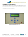
1
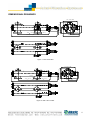
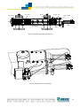
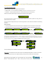
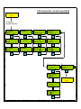
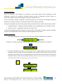
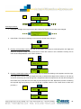
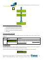
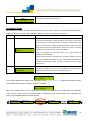
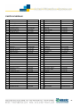
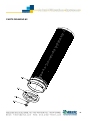
ARKAL Automatic Filters MG Series MG-110LP, MG-110LP-S Serial Number: Order Number: Catalog Number: Filtration Degree: Tested By: Installation, Operation and Maintenance Instructions 1 ARKAL Automatic Filters MG Series MG-110LP, MG-110LP-S Installation, Operation and Maintenance Instructions Disclaimer: This document and the information enclosed within it contain restricted and/or privileged information that are intended only for usage by authorized Arkal technicians. If you are not a qualified Arkal technician you must not take nay action in reliance to this document, unless permitted by Arkal. None of the procedures provided on this file may be used in any form or by any means without permission from Arkal. If you received this file in error please notify Arkal immediately. The confidential nature of and/or privilege in the file enclosed is not waived or lost as a result of a mistake or error in this file. Arkal accepts no liability whatsoever, whether it was caused by: 1. Accessing or other related actions to this file. 2. Any links, procedures or materials provided/attached to this file. Arkal assumes that all users understand risks involved within this file and/or its attached materials. All the procedures, drawings, pictures and/or any other information provided in this document are presented as general information only; they can be altered, removed or changed without any further notice by Arkal. This document does not replace any certified drawing, procedure or information provided by Arkal in reference to a specific customer, site or project. All rights reserved. 2 TABLE OF CONTENTS TECHNICAL SPECIFICATIONS ............................................................................................................................. 4 GENERAL ................................................................................................................................................................ 4 FLUSH DATA ............................................................................................................................................................ 4 CONSTRUCTION MATERIALS ..................................................................................................................................... 4 FILTRATION DEGREES AVAILABLE ............................................................................................................................. 4 DIMENSIONAL DRAWINGS ................................................................................................................................... 5 SAFETY INSTRUCTIONS ....................................................................................................................................... 6 GENERAL ................................................................................................................................................................ 6 OPERATION, CONTROL AND MAINTENANCE .............................................................................................................. 6 USE OF LIFTING EQUIPMENT .................................................................................................................................... 6 INTRODUCTION ...................................................................................................................................................... 7 GENERAL DESCRIPTION .......................................................................................................................................... 7 BASIC FILTER OPERATION ....................................................................................................................................... 7 HOW THE SELF-CLEANING CYCLE WORKS ............................................................................................................... 7 HOW THE FLUSHING CONTROLLER W ORKS .............................................................................................................. 9 HOW THE HYDRAULIC RELAY W ORKS ...................................................................................................................... 9 INSTALLATION ..................................................................................................................................................... 10 DESIGN RECOMMENDATIONS ................................................................................................................................. 10 PREPARATIONS FOR INSTALLATION ........................................................................................................................ 10 INSTALLATION INSTRUCTIONS ................................................................................................................................ 10 IMPORTANT! .......................................................................................................................................................... 10 FIRST-TIME OPERATION ................................................................................................................................. 11 SERVICING ............................................................................................................................................................ 11 DRAINING THE FILTER ........................................................................................................................................... 11 REMOVING AND INSTALLING THE INLET (COARSE) SCREEN ...................................................................................... 11 REPLACING THE PISTON.................................................................................................................................... 12 REMOVING AND INSTALLING THE FILTER SCREEN AND THE SUCTION SCANNER ................................ 12 MAINTENANCE ..................................................................................................................................................... 13 PREPARING THE FILTER FOR LONG-TERM SHUTDOWN OR FREEZING CONDITIONS ................................................... 13 PROGRAMMING THE FLUSHING CONTROLLER……………………………………………………… .14 PARTS SCHEDULE .............................................................................................................................................. 40 PARTS DRAWING #1 ............................................................................................................................................ 41 PARTS DRAWING #2 ............................................................................................................................................ 42 PARTS DRAWING #3 ............................................................................................................................................ 43 PARTS DRAWING #4 ............................................................................................................................................ 44 3 TECHNICAL SPECIFICATIONS General Maximum flow rate 3 450m /h; 1982USgpm Consult manufacturer for optimum flow depending on filtration degree & water quality. Min. Working pressure 2.0bar; 30psi Or lower if pressure is increased for flushing Max. Working pressure 10bar; 150psi Filter area 12,600cm²; 1,952in² Inlet/Outlet diameter 250mm, 10" MG-110LP MG-110LP-S 350m /h; 1542USgpm 3 0 Flange standards as per request. 0 Max. Working temperature 60 C; 140 F Empty weight MG110LP 325kg / 717lb Empty weight MG110LP-S 350kg / 770lb Flush data Exhaust valve 40 mm; 11/2" Three flushing valves Flushing cycle time 45 seconds Depending on the working pressure Wasted water per cycle 250liter; 70USgallon at 2bar; 30psi Minimum flow for flushing 30m³/h; 130USgpm at 2bar; 30psi Flush criteria Differential pressure of 0.5 bar; 7psi, time and manual operation Construction materials Filter housing Epoxy-coated carbon steel 37-2 (St. St. 316 available on request) Filter lid Epoxy-coated carbon steel 37-2 Coarse screen Reinforced nylon Fine screen Stainless Steel 316, molded plastic support structure Cleaning mechanism PVC and Stainless Steel 316L Motor assembly Reinforced nylon, brass, stainless steel Hydraulic piston Stainless Steel 316, brass Control tubing Polyethylene Seals BUNA-N Control Aluminum, Brass, Stainless Steel 316, PVC Filtration degrees available Type Molded screen Micron 500 300 200 130 100 80 mm 0.5 0.3 0.2 0.13 0.1 0.08 4 DIMENSIONAL DRAWINGS (43.3") 619 (24.3") 2482 (97.7") REF 404 (15.9") REF (11.8") 603 (23.7") REF 514 (20.2") REF 193 1100 300 DRAIN OUTLET INLET (7.6") 777 (30.6") REF 903 (35.5") REF Figure 1: MG 110LP Filter 1100 (43.3") 767 (30.2") 2680 (105.5") REF 193 404 (15.9") REF INLET (7.57") DRAIN OUTLET 603 (23.7") REF 300 (11.8") 777 (30.5") REF 514 (20.2") REF 903 (35.5") REF Figure 2: MG 110LP-S Filter 5 SAFETY INSTRUCTIONS General Carefully read the installation and operation instructions prior to installation or maintenance. While working with the filter all conventional safety instructions should be observed in order to avoid danger to the workers, the public or to property in the vicinity. Note that the filter enters into a self-cleaning cycle automatically, without warning. No changes or modifications to the equipment are permitted without written consent provided by the manufacturer or by its representative, on the manufacturer’s behalf. Operation, Control and Maintenance Do not open any cover bolts or fittings unless pressure in the filter has been released. Keep the work area around the filter clean and dry. Always open and close valves gradually. Manual cleaning of the filter element using high water pressure or steam should be performed in accordance with the cleaning system instructions. Manual cleaning of filter element using acid or other chemical agents should be performed in accordance with the relevant material safety instructions. Use of Lifting Equipment While using lifting equipment, make sure that the filter or the lifted part is chained securely and in a safe manner. Avoid working below lifted equipment. Wear a safety helmet while using lifting equipment. Attach the lifting equipment to the lifting eyes only. 6 INTRODUCTION General Description The MG110 is a sophisticated, yet easy-to-operate automatic filter, with a self-cleaning mechanism driven by a hydraulic turbine. It is designed to work with various types of screens in filtration degrees from 800 to 50 micron, and is available in 10" inlet/outlet diameter. The MG110 filter is configured to meet your specific needs according to flow rates and water quality. The filter can be installed as a stand-alone unit for low flow rates, or assembled in a group on a manifold when high flow rates and/or a large screen area are required. The filters are delivered fully assembled, requiring simple connections to the inlet and outlet, and to the drain. Basic Filter Operation Water enters the filter from the inlet pipe, and passes through a coarse screen, which protects the automatic cleaning mechanism from any large particles or debris. The coarse screen is not cleaned automatically, and should not accumulate large quantities of solids. The water then flows through a fine screen which filters out the smaller particles. Water that has passed through the fine screen is clean and passes into the outlet pipe. Particles of dirt accumulate on the fine screen and form a ―filtration cake,‖ which starts to restrict water flow. As the restriction, or clogging, increases, the pressure in the outlet pipe becomes lower than in the inlet pipe. When the pressure differential reaches a pre-set value, a self-cleaning cycle is initiated. The self-cleaning cycle takes approximately 45 seconds and does not interrupt the flow of water through the filter. How the Self-Cleaning Cycle Works At a preset pressure differential (0.5 bar —7 psi), which is detected by a pressure differential switch, the flushing controller operates pulse solenoids which allow water to flow to the relay valves, which then activate the hydraulic pistons and open a valve to the rotor chamber (See Figures 2 and 3). The water from the rotor chamber flows out the drain. The pressure in the rotor chamber drops, releasing a strong flushing stream that flows through the filter. This drop in pressure and corresponding release of the backflush stream create a suction effect at the nozzle inlets. This effect actuates spot cleaning directly in front of the openings of each nozzle at the inner side of the fine screen. The water and particles passing through the hydraulic rotor cause the suction scanner to rotate, and the piston moves in an axial direction to the opposite end of the filter. The combination of rotational and axial movement of the suction scanner assembly ensures that the nozzles sweep the entire inner side of the fine screen in a spiral pattern. When the first stroke is completed, the flushing valve closes and after a short interval the flushing controller activates the second backflush stroke. The suction scanner assembly spins, moving with the piston in the opposite direction and returning to its original position. This self-cleaning process takes about 45 seconds, depending on the operating pressure. It is essential that there be at least 2 bar pressure at the inlet to the filter for proper cleaning to take place during flushing. The flushing controller may be operated by pressure differential, manual activation, or by timer. 7 Exhaust valve Nozzle Fine screen Coarse screen Piston Dirt collector Inlet Rotor chamber Rotor Drain Outlet Figure 3: Internal Components of the MG 110 Figure 4: Hydraulic Control Line Routing 8 How the Flushing Controller Works The flushing controller is operated by 12 VDC. It receives a signal from the Differential Pressure Switch when the pressure differential reaches the preset value (0.5 Bar, 7 PSI). The flushing controller then sends a 12 VDC pulse to the Pulse Solenoid, which provides hydraulic pressure to the Hydraulic Relay which actuates the piston. Where there are several ganged filters, there are solenoids to each relay valve and piston and they are activated in turn, not simultaneously, in order to maintain inlet pressure and avoid large pressure drops. The unit can also control a downstream valve, which may be closed while flushing to increase pressure. An optional electronic counter can keep track of the number of flushing cycles. Parameters which may be set include: Mode of operation: Manual, Differential Pressure (DP) only, DP with time override Flushing cycle Flushing time Dwell Time DP response delay time Number of consecutive flushing cycles by DP, to be considered a fault How the Hydraulic Relay Works The hydraulic relay valve, when not actuated by hydraulic pressure from the pulse solenoid, allows pressure to pass to the hydraulic piston, extending it, and holding the suction scanner away from filter lid. When the hydraulic relay is actuated, pressure to the piston is shut off and the water in the piston flows out to the drain. When the piston is no longer under pressure the suction scanner pushes the piston away from the filter lid. COMMAND FILTER LID PRESSURE DRAIN DRAIN PISTON Figure 5: Hydraulic Relay 9 INSTALLATION Design Recommendations The inlet and outlet pipes must be the same or a larger diameter than the inlet and outlet diameters of the filter. The upstream pressure source should not drop below 30 psi (2 bar) during the rinse cycle. If this cannot be ensured, consult the manufacturer. If a prolonged pipeline fill time causes a temporary high flow and low pressure situation, it recommended that you install a pressure sustaining valve downstream of the filter. The pressure sustaining valve will ensure a controlled fillup of the line. If continued water delivery is essential even during ―down time‖ maintenance periods, it recommended that a manual or automatic by-pass be installed, and that isolating valves be installed up and downstream of each filter unit for isolation purposes. Shut off valves must be installed in the inlet and outlet lines to enable maintenance. A non-return valve should be installed where water hammer or back flow may be a problem. The filter must be installed in the direction of flow indicated by the arrow on the filter body. Secure the drain pipe so that there is no movement during flushing. The highest point of the drain pipe should be no more than one half meter above the filter. The drain pipe must allow free flow and be free of restrictions. Preparations for Installation Ensure suitable lighting at the area of the filter to enable good visibility and safe maintenance. Arrange suitable platforms and safety barriers to enable easy, safe access to the filter. Allow a convenient approach and enough space for dismantling and maintenance. Installation Instructions Ensure the direction of flow is according to arrows marked on the filter housing Install a drain valve in place of one of the pipe plugs in the inlet or outlet pipe on the installation manifold. Important! Prevent static back pressure or reverse flow through the filter. Install a manual or a hydraulic valve downstream of the filter. The filter may enter flushing mode automatically, without warning. 10 FIRST-TIME OPERATION 1. Remove a plastic plug from one of the outlet holes on the top of the filter to bleed air from the filter. 2. Open the inlet valve. 3. Close the plastic plug when all the air is bled from the filter. 4. Make sure the filter is clean and dry. 5. Check all fittings and flanges for leaks. 6. Open the outlet valve. 7. Perform manual flushing, by selecting ―Manual‖ in the flushing controller. 8. Check that the inlet pressure does not drop below 2 bar during flushing. The filter is ready for operation. Observe at least one automatic flushing cycle, activated by time or differential pressure. Servicing Draining the Filter 1. Close the inlet valve 2. Close the outlet valve. 3. Open the drain valve to release pressure. To avoid water draining onto the area around the filter, install a drain hose onto the drain valve. Removing and Installing the Inlet (coarse) Screen 1. Drain the filter. 2. Remove the filter cover nuts and the cover. 3. Remove the inlet screen. 4. Before reinstalling the screen, make sure that the fine filter screen is properly seated. 5. Push the coarse screen into place. 6. The screen must be seated in the base of the fine filter and must be flush with the flange of the filter housing or 1 mm. inside. It should not project outside the flange. 7. If the screen does not fit exactly, plastic segments may be removed or added as necessary. The screen is supplied with two spare segments stored as in the following figure. 8. Place the O-ring into the groove into the cover. It may be necessary to apply silicone grease to hold it in place. 9. Close the cover and tighten the nuts evenly in an alternating pattern. 10. Activate the filter as in the section "Operating the Filter for the First Time." A thick and a thin spare segment are stored here. Flush with flange or 1 mm inside Figure 6: Inlet Screen 11 Replacing the Piston 1. Drain the filter. 2. Remove the eight nuts holding the piston and cylinder assembly, and remove the assembly. 3. Inspect the suction scanner to make sure it moves freely in its bearings and the end that mates with piston is not damaged. 4. Apply silicon grease to the O-ring at the base of the piston/cylinder assembly. 5. Push the piston/cylinder onto the eight studs, taking care that the O-ring slides into the opening and seats properly. 6. Place nuts on the studs. Tighten gradually in a criss-cross pattern to avoid binding. 7. Activate the filter as in "Operating the Filter for the First Time." Removing and Installing the Filter Screen and the Suction Scanner 1. Drain the filter. 2. Remove the inlet screen. 3. Remove the piston and cylinder assembly. 4. Pull out the filter screen and suction scanner as an assembly. 5. Insert the filter screen/suction assembly making sure it is seated and is flush with the piston end of the filter housing. 6. Make sure that the suction scanner moves freely in its bearings. 7. Install the piston and cylinder assembly. 8. Activate the filter as in "Operating the Filter for the First Time." Should be seated and flush with flange surface Suction scanner must turn and slide freely Figure 7: Filter Screen/Suction Scanner Assembly 12 Maintenance It is recommended to inspect the filter once a year, in the off season. Remove the filter as described above and inspect the screen and O-rings, clean as necessary, and lubricate with silicone grease before reassembling. In cases where clogging of the inlet screen occurs, experience with the local conditions will determine how often the screen should be checked as a routine. Preparing the Filter for Long-Term Shutdown or Freezing Conditions 1. Drain the filter. 2. Remove the filter screens as described previously and clean and dry them. 3. Disconnect the hydraulic lines to drain water out of them and reconnect. 4. Push the piston rod inward to remove water from the cylinder. 5. Reassemble. 13 PROGRAMMING THE FLUSHING CONTROLLER Arkal’s Flushing-Controllers product line is a family of electronic devices capable of controlling the flushing process of various automatic-filter models. Currently this line consists of three products; one AC controller and two DC controllers. This document is the user-manual of the 6 solenoids DC Controller and it describes the configuration process and the operation procedures of the V7 controller version. Note: This picture is for illustration purpose only 14 Introduction & How to use this manual Arkal’s Flushing-Controllers product line is a family of electronic devices capable of controlling the flushing process of various automatic-filter models. Currently this line is consisting of three products; one AC controller and two DC controllers. This document is the user-manual of the 6 solenoids DC Controller and it describes the configuration process and the operation procedures of the V7 controller version. Before operating the controller please read this manual carefully. Make sure that: You are familiar with the safety instructions You know how to use the control’s User-Interface panel This manual consists of the following chapters: A. General description – The controller’s capabilities, the various configuration options and the types of filters the controller can serve – Page 17. B. Flushing methods – Detailed description of the various flushing sequences possible to operate with the controller – Page 17. C. The User Interface Panel - How to use the panel – Page 21. D. Entering data - How to modify numbers and parameters – Page 24. E. Configuration – How to configure the controller for a specific filter model – Page 26. F. Flushing program – How to enter a flushing sequence program - Page 28. G. Monitoring – How to monitor the controller operation - Page 30. H. Handling faults – How to identify and reset flushing faults – Page 31. I. Technical data – Connection drawing, I/O data, etc. – Page 32. J. Annex A. – Operating filters that require a Delay Valve 15 Safety instructions 1. The terminals enclosure lid of the unit must remain closed at all times. 2. Only a qualified technician may remove this lid and only when the controller is properly disconnected from its power source. 3. Servicing the unit can be done only by Arkal’s qualified technician. 4. Make sure that the filters controlled by the controller are disconnected from the water system whenever servicing the controller. 5. In case the controller is connected to an external AC power supply unit, make sure that the power supply connection is done properly and complies with your local standards for High Voltage out-doors connection. 6. No alterations or changes of the unit are allowed. 7. Never cut, connect or disconnect any wire at the controller’s vicinity. 8. Make sure that the controller is not exposed to water splashes. 9. Keep the keyboard transparent-cover closed at all times when not using the keyboard. 16 A. General Description Arkal’s DC Controller is an electrical/electronic device designed for controlling the flushing process of various types of automatic filters. The controller is capable of controlling up to 6 12VDC Latch Solenoids which enables it to operate several types of filtration sites such as: Automatic screen filters batteries, up to 6 units each. Gravel media filters batteries, up to 6 units each. Automatic disc filters batteries, up to 6 units each. One Arkal TAF Electronic Filter. Unlimited number of controllers can be chained together in order to control large filtration sites. The flushing process can be triggered by: Differential Pressure (DP) signal Time parameter Manual Start command Remote Start signal (By receiving an End of Cycle input from a chained controller) Beside the filters outputs and the DP input the controller is also capable of controlling the following additional functions: Main Valve (replaces one of the 6 maximum filter units outputs) Delay Valve (replaces one of the 6 maximum filter units outputs) Dry Contact Auxiliary Output that works in parallel with the main/delay valves Alarm output End of Cycle output Pause input The controller's enclosure is made of Polycarbonate and is designed for outdoor use (IP 65). B. Flushing Methods This chapter lists and describes the sequence of operation of the major flushing methods possible to operate using Arkal Flushing Controller: 1. Controlling Arkal TAF Electronic filter: 1.1 A single TAF filter: Starting the flushing cycle: DP signal: Once a signal from the DP switch is received the controller starts to count down the DP delay time (see screen number 7). If the signal remains present till the end of the count down a flushing cycle starts. Time parameter: By the end of each flushing cycle the controller starts to count down the Time between Flushes Parameter (see screen number 7). Once this parameter is counted down to zero a flushing cycle starts. Please note that if a flushing cycle is started by a different trigger (i.e. DP signal) the controller re-set the count down of the time between flushes parameter and starts to count it again. Manual Start: The user initiates a flushing cycle by pressing Enter in the ―For Manual Flush Press <Enter>‖ screen (see screen number 3). Remote start signal: Works the same as a regular DP signal. 17 The flushing cycle: Solenoid valve number 1 is switched on, the flushing of the filter starts and the controller counts down the Flushing Time parameter (see screen number 5). Once this parameter is counted down to zero the solenoid is switched off and the flushing cycle ends. 1.2 TAF filter with Downstream Valve: Starting the flushing cycle: The same as in ―A single TAF filter‖ above. The flushing cycle: The Main Valve solenoid is switched on and closes the filter’s downstream valve. The controller counts down the ―Delay Main Valve Close‖ parameter (see screen number 8). Once this count reaches zero the process moves to the next stage. Solenoid valve number 1 is switched on, the flushing of the filter starts and the controller counts down the ―Flushing Time‖ parameter (see screen number 5). Once this parameter is counted down to zero the solenoid is switched off and the process moves to the next stage. The controller counts down the ―Delay Main Valve Open‖ parameter (see screen number 8). Once this count reaches zero the Main Valve solenoid is switched off causing the downstream valve to reopen and the flushing cycle ends. 1.3 A battery of TAF filters: A battery of Arkal TAF filters consists of several TAF filters installed in parallel and serves the same water system. Each one of these filters has its own flushing controller but the actual DP sensor is connected only to the first filter of the battery. The End of Cycle output of the first filter controller is connected to the DP input of the second filter controller. The End of Cycle output of the second filter controller is connected to the DP input of the next filter controller and so on till the last filter in the battery. This arrangement allows a sequential flushing process where only one filter flushes at a time and the filters are flushed one after the other. Starting the flushing cycle: The first filter in the battery starts the flushing cycle in the same way as in ―A single TAF filter‖ above. Each one of the other filters of the battery start their flushing cycle by receiving a DP signal which is being sent for 15 seconds by the End of Cycle output of their previous filter in the battery. The flushing cycle: For each one of the filter of the battery it is the same as in ―A single TAF filter‖ above. 18 2. Controlling a single automatic screen or gravel media filter: 2.1 A single screen or gravel media filter: Starting the flushing cycle: The same as in ―A single TAF filter‖ above. The flushing cycle: 2.2 The same as in ―A single TAF filter‖ above. A single screen or gravel media filter with a Main Valve: Starting the flushing cycle: The same as in ―A single TAF filter‖ above. The flushing cycle: The same as in ―TAF filter with downstream valve‖ above. 3. Controlling a battery of automatic screen or gravel media filters: A battery of automatic screen or gravel media filters consists of 2-6 filters installed in parallel and serves the same water system, where one Arkal Flushing Controller controls the system. This arrangement allows a sequential flushing process where only one filter flushes at a time and the filters are flushed one after the other. Please note: The maximal number of filters in a battery controlled by a single controller is 6 where neither Main Valve nor Delay Valve are configured, 5 where a Main Valve or a Delay Valve is configured and 4 where both Main and Delay valves are configured. 3.1 A battery of screen or gravel media filters without a Main valve: Starting the flushing cycle: The same as in ―A single TAF filter‖ above. The flushing cycle: Solenoid valve number 1 is switched on, the flushing of the first filter of the battery starts and the controller starts to count down the Flushing Time parameter (see screen number 5). Once this parameter is counted down to zero the solenoid of the first filter is switched off and the process moves to the next stage. The controller counts down the ―Between Filters Delay‖ parameter (see screen number 5) and once this count reaches zero the controller switches on the solenoid of the second filter of the battery and starts to count down again the Flushing Time parameter. Once the flushing process of the second filter is finished the controller counts again the delay between filters and starts the flushing of the next filter. This process continues till the last filter is flushed and the flushing cycle is ended. 19 3.2 A battery of screen or gravel media filters with a Main Valve: Starting the flushing cycle: The same as in ―A single TAF filter‖ above. The flushing cycle: The Main Valve solenoid is switched on and closes the battery’s Main Valve. The controller counts down the ―Delay Main Valve Close‖ parameter (see screen number 8). Once this count reaches zero the process moves to the next stage. Solenoid valve number 1 is switched on, the flushing of the first filter of the battery starts and the controller starts to count down the Flushing Time parameter (see screen number 5). Once this parameter is counted down to zero the solenoid of the first filter is switched off and the process moves to the next stage. The controller counts down the ―Between Filters Delay‖ parameter (see screen number 5) and once this count reaches zero the controller switches on the solenoid of the second filter of the battery and starts to count down again the Flushing Time parameter. Once the flushing process of the second filter is finished the controller counts again the delay between filters and starts the flushing of the next filter. This process continues till the last filter is flushed and its solenoid is switched off, then the process moves to the next stage. The controller counts down the ―Delay Main Valve Open‖ parameter (see screen number 8). Once this count reaches zero the Main Valve solenoid is switched off causing the Main Valve to reopen and the flushing cycle ends. 20 C. The User Interface Panel Arkal’s Flushing Controller User Interface Panel consists of: Display screen - a 2 X 16 characters LCD display. (See picture on the front page of this manual.) Keyboard – a 5 keys keyboard divided into 4 directional Arrow keys and an Enter key. When the controller’s power supply is switched on the following screen appears: DC CONTROLLER v7 09/10/07 11:13 This is the entry point to a series of 13 main screens that each one of them by itself is an entry point to a specific function of the controller. Use the Left and the Right Arrow keys to move through these 13 main screens as indicated in the following illustration. Please note that: Pressing the Right Arrow Key when the last screen is displayed moves the view point to the first screen. Pressing the Left Arrow Key when the first screen is displayed moves the view point to the last screen. AC CONTROLLER v9 18/12/05 00:42 Status:B.Flushin Time: 4:23:35 AC CONTROLLER v9 18/12/05 00:42 Status:B.Flushin Time: 4:23:35 For manual flush Press <ENTER> Define controler Press code - XXX For manual flush Press <ENTER> Define controler Press code - XXX As indicated in the following illustration, in order to operate a specific function move first with the arrow key to the entry point of that function the nature of the specific function) (on the main 13 screens) and then use the Down Arrow or the Enter key (depends on to enter to requested function specific screens. Status:B.Flushin Time: 4:23:35 Delay main valve Close: 1 Open: 0 Enter 2A INPUTS OUTPUTS 00 00000000 Delay main valve Close: ? Open: 0 Enter Delay main valve Close: 1 Open: ? Enter The layout drawing of the controller’s screens appears in the following two pages. Please note: At the upper left corner of each screen in the following drawing there is a number. This number is used to identify the screen in the chapter describing its actual function further down at this manual. 21 Amiad's DC Filter Flushing Controller - User Interface Layout (Page #1) 1 2 DC CONTROLLER v7 09/10/07 11:13 Status:B.Flushin Time: 4:23:35 3 For manual flush Press <ENTER> 4 5 6 TimeBet.Flushing 5:00:00 (D:H:M) FlushTime: 00:20 Bet.Filt.: 00:10 Flu Til Fault: 3 Delay: 10 Enter 2A INPUTS OUTPUTS 00 00000000 To stop flushing Press <ENTER> Enter Enter TimeBet.Flushing █:00:00 (D:H:M) Enter FlushTime: ██:20 Bet.Filt.: 00:10 Enter Flu Til Fault: █ Delay: 10 Enter TimeBet.Flushing 5:██:00 (D:H:M) FlushTime: 00:██ Bet.Filt.: 00:10 Enter Enter Flu Til Fault: 3 Delay: ██ Enter TimeBet.Flushing 5:00:██ (D:H:M) Enter FlushTime: 00:20 Bet.Filt.: ██:10 Enter (Appears only on Fault) Enter Enter To Release D.P. Fault <ENTER> FlushTime: 00:20 Bet.Filt.: 00:██ Enter 7 8 9 10 11 Delay: D.P.: 19 Delay main valve Close: 1 Open: 0 Delay valve Open: 5 close: 5 Flushing counter 11 Set time 18/12/05 03:11 Enter Enter Enter Enter 12 Enter 13 Battery 6.14 Volt Define controler Press code - XXX Enter 10A Delay: D.P.: ██ Enter Delay main valve Close: █ Open: 0 Enter Delay main valve Close: 1 Open: █ Enter Delay valve Open: █ close: 5 Reason: by Manua 18/12/05 01:09 Enter Delay valve Open: 5 close: █ Enter Set time ██/12/05 03:11 Enter Flushing counter ██ Enter Define controler Press code - ███ Enter Set time 18/██/05 03:11 Enter Set time 18/12/██ 03:11 Enter Set time 18/12/05 ██:11 Enter Set time 18/12/05 03:██ Enter Continues on next page Amiad's DC Filter Flushing Controller - User Interface Layout (Page #2) Continues from page #1 See Chapter: How to Enter numbers and parameters 14 15 Select language * English Filter number: 4 Enter Select language █ English 16 Enter Filter number: █ Main valve: *yes Delay valve: *yes 17 DP Input: *yes Disc filter: *no Enter Enter Main valve: █yes Delay valve: *yes DP Input: █yes Disc filter: *no Enter Enter Select language █ Espanol Enter Filter number: 2 Enter Main valve: *no Delay valve: █yes DP Input: *no Disc filter: █yes Enter Enter 18 19 INPUTS OUTPUTS 00 ------00 To finish press <ENTER> Enter 19 Enter INPUTS OUTPUTS 00 █-----00 Return to page #1 INPUTS OUTPUTS 00 0-----00 INPUTS OUTPUTS 00 0█----00 Enter D. Entering Data When the controller is first installed it is necessary to enter and/or adjust its basic parameters. These parameters, entered to the controller’s nonvolatile memory through a Configuration Process, enable it to perform the suitable flushing method designed for the type of filters it serves. Once the controller is properly configured a Flushing Program has to be entered. This program defines the parameters according to which the controller performs the actual flushing of the filters. During the Configuration and the Flushing Program Entry procedures the user needs to enter two types of data: 1. Parameter selection – Selecting a required parameter from a predefined list in the controller’s memory 2. Entering numbers – Supplying the controller with numeric data The following paragraph explains the method of entering data to the controller in general. Specific instructions are given in the Configuration and the Flushing Program paragraphs of this manual. Selecting a parameter: 1. Using the Left/Right arrow keys move to the screen that contains the parameter to be selected. Press Enter. This will put a blinking cursor over the asterisk near the first parameter to be selected. Enter Main valve: yes Delay valve: *yes 2. Use the Up and Down Arrow keys to scroll through the list of possible options and select the required parameter. Then press Enter to store the parameter in the controller’s memory and to move to the next parameter in the current screen (A). Repeat the selection process with the Up and Down Arrow keys and then press Enter to return to the entry point screen (B). (Please note that if the screen contains only one parameter pressing Enter after the selection process will return you the entry point screen.) (A) Main valve: █no Delay valve: *yes Enter Main valve: *no Delay valve: █yes 24 Main valve: *no Delay valve: █no (B) Enter Main valve: *no Delay valve: *no Entering a Number: 1. Using the Left/Right arrow keys move to the screen that contains the number to be changed. 2. Press Enter. This will put a blinking cursor over the number to be changed. Enter Flu Til Fault: 3 Delay: 10 3. Entering a Single Digit number: Use the Up and Down Arrow keys to scroll through the 0-9 digits and select the required number. Then press Enter to store the number in the controller’s memory and to move to the next parameter in the current screen (A). (A) Flu Til Fault: 9 Delay: 10 Enter Flu Til Fault: 9 Delay: 10 4. Entering a Multi Digit number: Once the Enter key is pressed the blinking cursor appears over the rightmost digit of the number. Press the Right Arrow Key to delete all the digits of the number (B). Use the Up and Down Arrow keys to scroll through the 0-9 digits and select the required one for the left-most digit of the number, then press the Left Arrow Key to push this digit to the left. Repeat the process of selecting the required digit and pushing it to the left till the complete number is set. Press Enter to finish the process (C). Enter (B) Flu Til Fault: 9 Delay: 10 Flu Til Fault: 9 Delay: 25 (C) Example: Changing the Delay Parameter from 10 to 37: Press the Right Arrow Key to delete the ―10‖ digits. Use the Up or the Down Arrow Key to select "3". Press the Left Arrow Key to push the ―3‖ to the left. Select "7" by using the Up or the Down Arrow Key. Press Enter. Setting the Real Time Clock Once power is first connected to the controller the real time clock needs to be set. This is done at screen number 11. Number Screen Description 11 Set time 18/12/05 03:11 Navigate to this screen, press Enter and set the controller’s clock according to your local time zone and date. Note: do not change the clock setting while flushing. E. Configuration After the installation of the controller and prior to the first operation it is necessary to perform the configuration process in order to synchronize the controller with the filters it be flushed. Start the configuration process by navigating to screen number 13 and entering 123 in the code field. Define controler Press code - XXX 26 Important notes: Never change the controller’s configuration while flushing. Once the controller is configured EXIT the configuration process, the controller is not operational while in configuration mode. The layout of the screens involved in the configuration process can be found on page 11 of this manual. The following table describes each one of the screens of the configuration process and it contains three columns. The first column shows the screen number as appears at the upper left corner of the screen drawing in the layout diagram on page 11 of this manual. The second column shows the default setting of the screen. The third column explains the controller-task controlled by this screen. Number 14 15 Screen Select language * English Filter number: 4 Description Select the user interface language of the controller. Currently it is possible to choose English or Spanish. Upper line: Defines the number of filters (solenoids) controlled by the controller. 16 Upper line: Main valve: *yes Delay valve: *yes Defines if the controller activates a Main Valve. Lower line: Defines if the controller activates a Delay Valve. Notes: 1. See chapter B for a description of the Main Valve operation. 2. See Annex A. for a description of the Delay valve operation. 3. If only a Main Valve or a Delay Valve is selected the solenoid of this valve is assigned to Output Number 6. However if both Main Valve and Delay Valve are selected the Delay Valve solenoid is assigned to Output Number 5 and the Main Valve is assigned to Output Number 6. 17 Upper line: DP Input: *yes Disc filter: *no Defines if in addition to the ―start by time‖ the flushing process may start also by a signal received from a Differential Pressure sensor. Lower line: Defines the type of the controller’s reaction in case where the DP continues to signal at the end of the flushing cycle. Note: See chapter H for DP fault description. 27 Number Screen 18 Description This screen helps the technician installing or servicing the controller to INPUTS OUTPUTS 00 ------00 verify the status of the controllers I/O. Inputs: Left digit - DP sensor status: 0= no DP signal 1= DP signal is present Right digit – Pause input status: 0=no Pause signal 1= Pause signal is present Outputs: The first 6 digits from the left show the status of the filters, the main valve and the delay valve outputs: 0= The output is switched off 1= The output is switched on - = There is no solenoid connected to this output Digit number 7 (from left) – Alarm signal: 0= No Alarm signal (the Alarm output is switched off) 1= Alarm signal (the Alarm output is switched on) Digit number 8 (from left) – End of Cycle (sequence) signal: 0= The Sequence signal is off 1= The Sequence signal is on and being sent to activate the flushing process of another controller. 19 Press Enter to exit the Configuration process and return to the Main To finish press <ENTER> Screen (to Screen number 1). Notes: This is the only exit point of the configuration process, navigate to this screen and press Enter to terminate it. The controller begins automatic operation only after exiting the Configuration process!!! F. Flushing program Once the controller is properly configured and the real time clock is set it is necessary to enter a flushing program in order for the actual operation of the controller to start. The layout of the screens involved in the Flushing program entry can be found on page 10 of this manual. The following table describes each one of the screens of the Flushing program and it contains three columns. 28 The first column shows the screen number as appears at the upper left corner of the screen drawing in the layout diagram on page 10 of this manual. The second column shows the default setting of the screen. The third column explains the controller-task controlled by this screen. Note: Do not change the program while flushing, stop the flushing first. Number Screen Description 4 TimeBet.Flushing 5:00:00 (D:H:M) This screen defines the time between scheduled flushing cycles. The 5 entry format is Days (0-99), Hours (0-23) and minutes (0-59). Upper line: FlushTime: 00:20 Bet.Filt.: 00:10 Defines the flushing time (the duration of flushing) of one filter. The entry format is Minutes (0-99) and Seconds (0-59). Lower line: Defines the delay time between filters (between the end of one filter flushing and the beginning of the next). The entry format is Minutes (0XX) and Seconds (0-59). 6 Upper line: Flu Til Fault: 3 Delay: 10 Defines the number of maximum flushing cycles till fault; the maximum allowed number of continuous flushing cycles when the DP signal remains continually ON (probably due to a filter clog). If this number is exceeded the controller enters into Fault mode and activates the alarm. The entry format is 0-9. Lower line: Defines the delay between one flushing cycle and the next when the controller receives a continuous signal from the DP switch. The entry format is Seconds (0-99) 7 Defines the time required for the DP signal to remain ON until the Delay: D.P.: 19 controller responds by activating the flushing cycle. The entry format is Seconds (0-99). Note: This screen appears only if a main valve is configured and it 8 Delay main valve Close: 1 Open: 0 defines the main operation as described in chapter B. Close: The time between closing the main valve and activating the flushing cycle. Open: The time between deactivating the flushing cycle and opening the main valve. The entry format is Seconds (0-99). Note: This screen appears only if a Delay valve is configured and it 9 Delay valve Open: 5 close: 5 defines the Delay valve operation as described in Annex A. The entry format is Seconds (0-99). 29 G. Monitoring During the regular operation of the controller it is possible to: Monitor the current status of the controller Read information on past activities of the system Perform manual operation and intervene in the flushing process Read and monitor the voltage of the controllers battery The layout of the screens involved in the controller’s Monitoring can be found on page 10 of this manual. The following table describes each one of the controller’s Monitoring screens and it contains three columns. The first column shows the screen number as appears at the upper left corner of the screen drawing in the layout diagram on page 10 of this manual. The second column shows the default setting of the screen. The third column explains the controller-task controlled by this screen. Number Screen 2 Description This screen shows the current status of the controller. The upper line: - shows the current status, The possible messages are: Flushing (the flushing filter number is also displayed) Between filters (counting the delay between filters) Between flushing cycles (counting the time to the next flushing cycle) Status:B.Flushin Time: 4:23:35 Delay (counting the D.P. delay) Fault (the controller is at D.P. fault) The lower line: - shows the countdown of the time related to the upper line message, for example: When the controller is between flushing cycles this line shows the time left to the next flushing cycle. When filter number 1 is flushing this line shows the time left for this filter to flush. 3 In this screen the user can manually start and stop a flushing cycle. For manual flush Press <ENTER> Press Enter to immediately initiate a flushing cycle. Once the cycle is started the controller displays the status screen (screen number 2). Press the right arrow key to return to this screen. In order to stop the flushing cycle press Enter again, otherwise the flushing cycle will continue till its regular completion. 10 This screen displays the number of flushing cycles performed since the Flushing counter 11 last time this filed was cleared. The controller stores a record showing the start time and reason (PD, Time or Manual) for each one of the last 50 flushing cycles. Use the Up and Down arrow keys to scroll through these records. Press Enter to edit and clear the flushing counter. 30 This screen shows the voltage of the controller’s battery. 12 Battery 6.14 Volt The minimum operational level is 4.7 V H. Handling faults Arkal’s flushing controller can detect and respond to filter clogs. This is done by monitoring the status of the D.P. signal. The user can configure the controller’s response through the following two screens: Number Screen Description 6 If by the end of a flushing cycle the D.P signal remains ON the controller counts down the delay entered in this screen (in seconds), and if by the end of this delay the D.P. is still ON a new flushing cycle starts. In case the D.P. remains permanently ON the delay is counted again and this process repeats till the ―maximum number of flushing Flu Til Fault: 3 Delay: 10 cycles till fault‖ entered at this screen is exceeded. Once this happens the controller enters into a Fault Status as described below this table. Please note that if zero is entered at the ―maximum flushing cycles till fault‖, the controller never enters to ―D.P. Fault Status‖ and continues to initiate new flushing cycles constantly whenever the D.P. signal remains ON. If the lower line parameter of this screen is set to ―Disc filter *yes‖ the 17 DP Input: *yes Disc filter: *no controller immediately enters to ―D.P. Fault Status‖ whenever the D.P. signal remains ON at the end of the first flushing cycle. When the controller enters to D.P. Fault the main status screen (Screen number 2) shows the fault status and time. Status:D.P. Fault Time: 4:23:35 A new screen appears to the right of the main status screen (Between screens 2 and 3) displaying the option to reset and release the fault and the controller’s buzzer is activated. To Release D.P. Fault <ENTER> When the controller enters to D.P. Fault check if the filters are clogged and if needed clean them manually. Check the D.P. switch and then cancel the fault by navigating to and pressing Enter in the ―Release Fault Screen‖ which appears between screens 2 and 3. AC CONTROLLER v9 18/12/05 00:42 Status: D.P. Fault Time: 4:23:35 To Release D.P. Fault <ENTER> For manual flush Press <ENTER> Define controler Press code - XXX 31 Battery and power levels: In order to prolong the battery life the controller switches off the display screen of the unit once the keyboard is not used. In such case the operation of the unit continues as usual. Press any key to switch on the display screen. The required voltage level for regular operation is 4.7-12 Volts. Once the voltage level drops below 4.7 V the controller stops its regular operation, switches on the Alarm and enters into Fault status. I. Technical data Electrical Connections: The Electrical Connections Board External Power supply 6-12 VDC: This connection terminal is used to connect, when available, a 6-12 VDC 500 milliamp external power supply unit to the controller. Once such external power supply is connected the internal batteries of the controller are used only for a backup and not for the actual operation of the controller. 32 Outputs: OUT1-OUT6: These are the terminals for the Two Wire 12V DC Solenoids. If a main valve or a delay valve has been designated during the controller’s configuration process, it's solenoid's output will always assigned to Output Number 6. For example, if two outputs are defined as filters (OUT1-OUT2), the main valve output will be OUT6. If both main valve and delay valve are defined, Output Number 5 will be the delay valve output and the Output Number 6 will be the main valve output. Auxiliary Output (marked on the controller’s terminal strip as Main Valve): This output is opened and closed automatically by the controller in parallel to OUT-6, i.e. this output is activated whenever OUT-6 is activated. Alarm: This output is a Dry Contact Relay (a free potential contact); it provides a command pulse to an external alarm device. The alarm is activated in two cases: When a selected number of consecutive flushing cycles have taken place due to continuous differential pressure input signal, which usually occurs when the filters are clogged. When the battery voltage is lower than 4.7 VDC End of Cycle (End C): This output is a Dry Contact Relay (a free potential contact); at the completion of a flushing cycle it provides a command pulse connected to the D.P. input of an external controller (slave). This pulse lasts 5 seconds and takes place after all the other outputs of the flushing process have been activated and de-activated. See ―Chaining Arkal Controllers‖ drawing at the end of this chapter. Note: This output in marked as SEO in the AC controller, the functionality is the same and therefore it is possible to chain AC and DC controllers. Inputs: D.P.: This is the connection to the differential pressure switch. Pause: Connecting these two terminals creates a signal which causes the controller to stop operating until the connection between these two terminals is disconnected. 33 Installing and replacing the batteries: The controller is powered by four D batteries. The unit starts to operate automatically 10 seconds after inserting the batteries. Alternatively, an external 6-12V DC supply can be connected to the power connection terminal; (Labeled as 6-12 VDC on the terminal board circuit board.) If an external power supply is connected while a set of batteries is installed, the batteries are served as a backup and are not in use as long as the external power supply is connected. In order to install or replace the batteries: Open the transparent keyboard lid. Unscrew the 4 screws located in the corners of the keyboard and screen panel. Remove the panel from the controller housing to get access to the battery compartment. Insert 4 D type 1.5VDC batteries according to the (+) and (–) marks on the compartment. Insert the panel and cover the battery compartment. Re-screw the 4 screws and close the transparent lid. 34 I/O Terminal Connections Drawing: 35 Chaining Arkal Controllers: In order to operate a battery of screen or gravel media filters that include a larger number of filters than one Arkal’s Flushing Controller can handle, it is possible to chain few controllers for the job. The D.P. switch that reads the pressure drop across the battery is connected to the first controller of the chain (the Master). The SEQ (or End of Cycle) output of the master controller is connected to the D.P. input of the second controller of the chain (the first slave) and this controller SEQ output is connected to the D.P. input of the nest. This type of connection can be spanned over as many controllers as needed. When the actual D.P. switch send a signal the master controller starts a flushing cycle. Once this cycle is completed the master controller sends a signal through its SEQ output to the second controller to start its flushing cycle, and so on till the last controller in the chain as illustrated in the following drawing. Master Controller Slave 1 Controller Slave N Controller Enter Enter Enter D.P SEQ Input Output D.P Input SEQ D.P SEQ Output Input Output Standard D.P. Switch 36 J. Annex A. – Operating filters that require a Delay Valve In some cases there is a need to control a Delay Valve together with the filtration system, for example in installations where a delay Valve is used for sampling the flushing water. Arkal’s Flushing Controller contains two parameters which allow the user to control a filtration system that requires a Delay Valve; these are the ―Delay Valve Open‖ and the ―Delay Valve Close‖ parameters (see screen number 9). Please not that: Each one of these parameters should be shorter than the ―Flushing Time‖ Parameter. The addition of the time set for the ―Delay Valve Open‖ parameter with the time set for the ―Delay Valve Close‖ parameter should be shorter than the time set for the ―Flushing time‖ parameter. The following is a step by step description of the controller operation in installations that include a delay valve: 1. A single screen or gravel media filter with a Delay valve: Starting the flushing cycle: The same as in ―A single TAF filter‖ above. The flushing cycle: Solenoid valve number 1 is switched on and the flushing of the filter starts. The controller starts to counts down two parameters in parallel: The ―Flushing Time‖ parameter screen number 5) and (see the ―Delay Valve Open‖ parameter (see screen number 9). Once the ―Delay Valve Open‖ parameter is counted down to zero the Delay solenoid is switched on. During the flushing process when the count down of the ―Flushing Time‖ reaches a value which is equal to the ―Delay Valve Close‖ parameter (see screen number 9) the controller switches off the Delay Valve solenoid. Once the ―Flushing Time‖ parameter is counted down to zero the solenoid is switched off and the flushing cycle ends. 1.1 A single screen or gravel media filter with both Main and Delay valves: Starting the flushing cycle: The same as in ―A single TAF filter‖ above. The flushing cycle: The Main Valve solenoid is switched on and closes the filter’s downstream valve. The controller counts down the ―Delay Main Valve Close‖ parameter (see screen number 8). Once this count reaches zero the process moves to the next stage. Solenoid valve number 1 is switched on and the flushing of the filter starts. 37 The controller starts to counts down two parameters in parallel: The ―Flushing Time‖ parameter screen number 5) and (see the ―Delay Valve Open‖ parameter (see screen number 9). Once the ―Delay Valve Open‖ parameter is counted down to zero the Delay solenoid is switched on. During the flushing process when the count down of the ―Flushing Time‖ reaches a value which is equal to the ―Delay Valve Close‖ parameter (see screen number 9) the controller switches off the Delay Valve solenoid. Once the ―Flushing Time‖ parameter is counted down to zero the filter solenoid is switched off and the process moves to the next stage. The controller counts down the ―Delay Main Valve Open‖ parameter (see screen number 8). Once this count reaches zero the Main Valve solenoid is switched off causing the downstream valve to reopen and the flushing cycle ends. 2. A battery of screen or gravel media filters with a Delay Valve: Starting the flushing cycle: The same as in ―A single TAF filter‖ above. The flushing cycle: Solenoid valve number 1 is switched on and the flushing of the first filter of the battery starts. The controller starts to counts down two parameters in parallel: The ―Flushing Time‖ parameter screen number 5) and (see the ―Delay Valve Open‖ parameter (see screen number 9). Once the ―Delay Valve Open‖ parameter is counted down to zero the Delay solenoid is switched on. Once the Flushing Time parameter is counted down to zero the solenoid of the first filter is switched off and the process moves to the next stage. The controller counts down the ―Between Filters Delay‖ parameter (see screen number 5) and once this count reaches zero the controller switches on the solenoid of the second filter of the battery and starts to count down again the Flushing Time parameter. Once the flushing process of the second filter is finished the controller counts again the delay between filters and starts the flushing of the next filter. This process continues till the last filter starts to flush, then the process moves to the next stage. During the flushing process of the last filter of the battery and when the count down of the ―Flushing Time‖ reaches a value which is equal to the ―Delay Valve Close‖ parameter (see screen number 9) the controller switches off the Delay Valve solenoid. Once the ―Flushing Time‖ parameter of the last filter is counted down to zero the filter solenoid is switched off and the flushing cycle ends. 2.1 A battery of screen or gravel media filters with both Main and Delay valves: Starting the flushing cycle: The same as in ―A single TAF filter‖ above. 38 The flushing cycle: The Main Valve solenoid is switched on and closes the battery’s Main Valve. The controller counts down the ―Delay Main Valve Close‖ parameter (see screen number 8). Once this count reaches zero the process moves to the next stage. Solenoid valve number 1 is switched on and the flushing of the first filter of the battery starts. The controller starts to counts down two parameters in parallel: The ―Flushing Time‖ parameter screen number 5) and (see the ―Delay Valve Open‖ parameter (see screen number 9). Once the ―Delay Valve Open‖ parameter is counted down to zero the Delay solenoid is switched on. Once the Flushing Time parameter is counted down to zero the solenoid of the first filter is switched off and the process moves to the next stage. The controller counts down the ―Between Filters Delay‖ parameter (see screen number 5) and once this count reaches zero the controller switches on the solenoid of the second filter of the battery and starts to count down again the Flushing Time parameter. Once the flushing process of the second filter is finished the controller counts again the delay between filters and starts the flushing of the next filter. This process continues till the last filter starts to flush, then the process moves to the next stage. During the flushing process of the last filter of the battery and when the count down of the ―Flushing Time‖ reaches a value which is equal to the ―Delay Valve Close‖ parameter (see screen number 9) the controller switches off the Delay Valve solenoid. Once the ―Flushing Time‖ parameter of the last filter is counted down to zero the filter solenoid is switched off and the process moves to the next stage The controller counts down the ―Delay Main Valve Open‖ parameter (see screen number 8). Once this count reaches zero the Main Valve solenoid is switched off causing the Main Valve to reopen and the flushing cycle ends. 39 PARTS SCHEDULE No. Description Cat. No. No. Description Cat. No. 1 Filter housing (2 x 10⁶XLP) 15-1100-9222 4 Piston lid assembly (CI) 15-1070-0591 Filter housing (2 x 10⁸LP) 15-1105-6222 4.1 Piston lid 55-1070-1093 1.1 Plastic plug 1" 83-9810-0100-3000 4.2 Plastic plug 1/4" 82-11-0121-0400 1.2 L-Connector 3/8" X 12 82-11-7469-5206 4.3 L-Connector 1/4" X 6 82-11-6469-4604 1.3 L-Connector 1/4" X 6 82-11-7469-4604 4.4 Piston shaft 65-1005-0522 1.4 Arkal Controller 6 DC 84-87-45-0007 4.5 Exhaust valve seat 65-1006-0505 1.4.1 PD switch UE 24-011 84-34-10-0002 4.6 Disc seal seat 65-1006-0503 1.4.2 Solenoid 12VDC "NO" (S985) 82-21-2012-0002 4.7 O-Ring P2-009 81-41-4000-0009 1.4.3 St.St. Nut M6 85-2212-06-000 4.8 Rod 65-1006-0502 1.4.4 St.St. Washer M6 85-2312-06-000 4.9 O-Ring P2-009 81-41-4000-0009 1.4.5 St.St. Bolt M6 X 20 85-2112-06-020 4.10 Exhaust valve seat 65-1006-0591 1.5 Stud bolt 1/2" X 50 (X8) 85-2431-08-050 4.11 O-Ring P2-351 81-41-4000-0351 1.6 Plastic plug 3/4" 83-9810-0075-3000 4.12 Locking ring 65-1006-0592 2 Fine screen 106XLP 15-1603-xxxx 4.13 Disc seal seat 65-1006-0503 Fine screen 108LP 15-1803-xxxx 4.14 Bearing 55-1006-0504 2.1 O-Ring 647 81-41-4001-0674 4.15 St.St. Nut 1/4" 85-2211-04-000 2.2 Handle bolt 106 LP/XLP 8521-2101-008 4.16 O-Ring P-237 81-41-4000-0237 Handle bolt 108LP 8541-2101-008 4.17 U-Ring 95X75X10 81-41-4561-0530 Handle 106 LP/XLP 61-5510-0152 4.18 Seal holder 65-1006-0539 2.3 Handle 108LP 61-5510-0154 4.19 U-Ring 95X75X10 81-41-4561-0530 2.4 Spacer disc 65-3903-0123 4.20 St.St. Cylinder 65-1006-0527 2.5 Fine screen bearing 65-3003-0204 4.21 Piston rod tie 65-1005-0593 3 Dirt collector ass. 106XLP/108LP 15-1004-5046 4.22 O-Ring P-237 81-41-4000-0237 3.1 O-Ring 647 81-41-4001-0674 4.23 Piston lid 65-5510-0006 3.2 Rotor assembly 55-1006-0011 4.24 St.St. Lock nut 1/4" 85-2231-04-000 3.2.1 Rotor 55-5510-0023 4.25 St.St. Washer M6 85-2312-06-000 3.2.2 Rotor adaptor 51-5510-0015 4.26 Plastic plug 1/4" 82-11-0121-0400 3.2.3 Rotor bearing housing 65-1024-0026 5 Coarse screen 106XLP 15-3002-0003 3.2.4 Lower Bearing 65-1004-0601 Coarse screen 108LP 15-3002-0001 3.3 F. chamber flat screen 15-1070-0506 6 Flat Filter lid 55-1070-1091 F. chamber ZZ screen 15-1070-0508 7 O-Ring P2-448 81-41-4000-0448 3.4 Dirt collector 106XLP/108LP 15-1004-0016 8 Nut 1/2" 85-1211-08-000 3.4.1 Bolt 3/8" X 8 85-4125-08-009 9 Washer M12 85-1312-12-000 3.4.2 Dirt collector pipe 106XLP/108LP 65-1064-0547 10 Hydraulic relay 25-300 15-1009-0032 3.4.3 Nozzle assembly 55-1024-0357 10.1 L-Connector 3/8" X 8 82-11-7469-5204 3.4.4 Collector connecting bolt 65-3044-0451 10.2 L-Connector 3/8" X 12 82-11-7469-5206 3.4.5 Support bolt 51-5510-0010 10.3 Connector 1/8" X 6 82-11-7468-4602 3.4.6 Dirt collector shaft 65-3044-0110 11 Nipple 11/2" NPT 83-2920-0151-0105 3.4.7 Dirt collector top plug 51-5510-0024 Nipple 11/2" BSP 83-2920-0150-0105 40 PARTS DRAWING #1 41 PARTS DRAWING #2 42 PARTS DRAWING #3 43 PARTS DRAWING #4 44