1
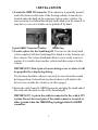
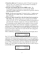
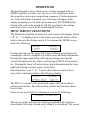
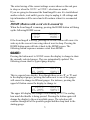
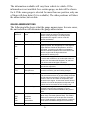
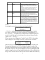
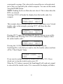
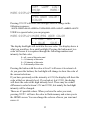
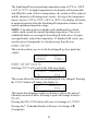
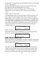
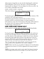
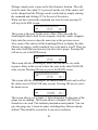
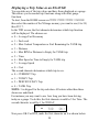
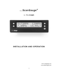
the ScanGauge I I by LinearLogic I N S TAL L AT I O N AN D O P E R AT I O N www.scangauge.com www.linear-logic.com i WAR N I N G Use of the ScanGaugeII while driving could lead to an accident and serious injuries. The primary attention of the driver should always be on safe driving. As with any gauge or other instrumentation system in a motor vehicle, the information should be observed as part of a normal sequence of observations performed in the operation of the vehicle. Changes to the selections in the ScanGaugeII should only be made when it is safe to do so. The driver must remain attentive to driving the vehicle. The mounting of the ScanGaugeII and the routing of the cable connecting it to the vehicle should be done with suitable caution that it does not create an unsafe condition. This includes but is not limited to the following: • Don’t mount the ScanGaugeII where it can obstruct the view of the driver. • Don’t mount the ScanGaugeII in a manner which could cause it to be propelled through the vehicle during an accident causing injury, such as over or near an air-bag. • Don’t route the cable in a manner which would interfere with the operation of the vehicle controls. R I G H T S AN D O B L I G AT I O N S The ScanGaugeII may be used on any number of vehicles. The software contained in the ScanGaugeII is copyright protected by Linear-Logic and may not be transferred or disassembled and used in another product, in part or in whole. The artwork used in generation of the circuitry is also copyright protected and cannot be used in part or whole by any person or entity without the express written permission of Linear-Logic. 2004-2007 Linear-Logic. All rights reserved. Version 5.0 Information in this manual and the specifications and operation of the ScanGaugeII itself are subject to change without notice. ii I N S TAL L AT I O N 1) Locate the OBD II Connector. This connector is normally located under the dash on either side of the steering column. It can also be located under the dash on the passenger side in some vehicles. On rare occasions it is behind the ashtray in the dash or in the armrest. It may have a cover on it which can be pulled off by hand. Typical OBDII Connector Location OBDII Plug 2) Locate a place for the ScanGaugeII. You can use the sticky-back velcro supplied with the ScanGaugeII to attach it to the location you have chosen. The velcro attachment allows you to easily remove it and use it to trouble-shoot another vehicle and then return it to this vehicle. IMPORTANT: Don’t place it on an airbag cover or where it will be propelled by a deploying airbag. The location should be where it can easily be seen from the normal driving position. It should not be placed where it will obstruct the drivers view outside the vehicle or of other gauges. 3) Route the cable from the OBDII connector and plug the small end of the cable into the back or side of the ScanGaugeII. IMPORTANT: A pin in the cable is connected to the vehicle 12V system. Do not short any pins of the small connector to metal or other ground when the OBDII Plug is plugged into the OBDII connector. 1 4) Turn the vehicle on. If it can be run, start it. If it can’t be run, turn the key to the “run” position. This is the position it is normally in when the vehicle is being driven. 5) Plug the ScanGaugeII Plug into the OBDII socket. The ScanGaugeII derives all the power it needs from the OBDII connector. No other connections are needed for its operation. Wait for the ScanGaugeII to Connect. NOTE: If it does not stop saying "Connecting..." or the screen goes blank after 60 seconds, refer to “TROUBLESHOOTING” on page 24 and 25. 6) Perform Vehicle Setup if this is the first time it has been used on this vehicle. The various settings can be reached from the HOME screen via MORE>SETUP and choosing the different setup options to select the units of measure, engine size, fuel type and fuel tank size. The information can be changed and saved again as often as needed. When the ScanGaugeII is first connected, it attempts to communicate with the vehicle. Communications can be established with the key in the run position, even if the engine is not actually running. It could take up to 60 seconds for the connection to be made after the unit is plugged in with the key in the run position. While establishing communications, the first line on the display shows: Connecting... <TRIP MORE> The TRIP and MORE buttons can be used even if a connection is not established. If communications with the vehicle ECU is not completed within about 75 seconds, the ScanGaugeII goes to sleep. It will continue to attempt to connect when the vehicle is restarted or the HOME button pressed. When communications has been established, the display will change over to that which was displayed the last time it went to sleep or to the HOME screen : <SCAN <TRIP GAUGE> MORE> 2 O P E R AT I O N The ScanGaugeII is easy to hook up to a vehicle equipped with an OBDII connector. It is also very easy to use. The operation is menu driven and does not require memorizing sequences of button presses to use. After each button is pressed, new selections will appear in the display prompting you for what can be done next. The HOME button (button with a red circle around it) will take you back to the starting point at any time, or activate the ScanGaugeII if asleep. MENU DRIVEN SELECTIONS The Menu/Select buttons are located at each corner of the display. When a ‘< <’ or ‘>’ is displayed next to the button, pressing the button will do what is shown in the display next to it. For instance the HOME screen shows the following: <SCAN GAUGE> <TRIP MORE> Pressing the button at the upper-left corner will bring up selections for scanning the vehicle’s computer for trouble codes and other information. Pressing the upper-right button will bring up Gauges showing the current information for the vehicle, such as Speed, RPM, fuel economy, etc.. Pressing the lower-left button shows trip information and the lower right button brings up more types of selections. Sometimes there is no ‘<’ or ‘>’ next to the button. In most of these cases, this is information like in the following display: P0321 CLEAR> <PREVIOUS NEXT> The P0321 is a trouble code, pressing the upper left button will not perform any function. The other buttons perform the functions shown next to them. Some screens are strictly for information, such as the following: Codes Cleared This screen will be shown if the vehicle responds that all codes have been cleared following a button press telling it to clear them. This screen 3 is exited by pressing the HOME button, returning you to the starting screen. AUTOMATIC SLEEP MODE About 12 seconds after turning off the vehicle or pressing a button after the vehicle engine is turned off, the ScanGaugeII will automatically power down into a sleep mode. The display will go blank and the backlighting will turn off if it was on. Starting the engine or pressing the HOME button will automatically reactivate the ScanGaugeII and it will return to the screen and lamp settings it had just before it went to sleep. AUTOMATIC MODE RECOGNITION Different vehicles use different types of signaling from their computers. In most cases, the ScanGaugeII can quickly determine which type your vehicle is using. You don’t have to know which type it is for it to be used. AUTOMATIC REPEAT BUTTONS Pressing the buttons and holding them for more than a second will cause them to automatically repeat at a rate of about 2 times a second. This allows for rapid stepping to a value without a lot of button pressing. USER PROGRAMMABLE GAUGES Up to 25 trip, vehicle specific or special gauges can be entered into the ScanGaugeII. These are stored in flash memory and will be retained even if there is a power loss, but the user can change them as often as desired. USER PROGRAMMABLE COMMANDS Up to 10 commands can be generated, edited, saved and sent to the vehicle computer. This allows for future codes and some special commands to be added by the user. FLASH MEMORY The ScanGaugeII II uses a type of memory which doesn’t require batteries or a source of power to maintain. This means that your settings will not be lost if you disconnect the vehicle battery or disconnect the ScanGaugeII. 4 The actual saving of the current settings occurs whenever the unit goes to sleep or when the SAVE> or DONE> selections are made. If you are going to disconnect the ScanGaugeII to use it to troubleshoot another vehicle, wait until it goes to sleep to unplug it. All settings and trip information will be saved and will continue when it is reconnected later. HOME (Button with a red circle around it) When the ScanGaugeII is running, pressing the HOME button will bring up the following HOME screen: <SCAN GAUGE> <TRIP MORE> If the ScanGaugeII is asleep, pressing the HOME button will cause it to wake up to the screen it was using when it went to sleep. Pressing the HOME button again will take it back to the HOME screen. The following button sequences assume a start from HOME. GAUGE> Pressing the button next to GAUGE causes the display to change to show the currently selected gauges. They are automatically updated. The following screen shows a typical gauge display: 710RPM 28MPH 15.2MPG 50FWT This is a special case display. Even though there are no ‘<’ or ‘>’ next to the displayed gauges, pressing the button next to one of the gauges will cause it to change to different gauges. For instance, pressing the upper left button causes the display to change to: 10TPS 28MPH 15.2MPG 50FWT The upper left display has changed from reading the RPM to reading how much the throttle is being pressed. Pressing the button again will change the display to the next available gauge. The selection will continue through all of the possible gauges and then loop back to the starting gauge. 5 The information available will vary from vehicle to vehicle. If the information is not available for a certain gauge, no data will be shown for it. If the same gauge is selected for more than one position, only one of them will show data (if it is available). The other positions will show the abbreviation, but no data. GAUGE ABBREVIATIONS The following table shows what the gauge names mean. In some cases, the unit selection will determine the gauge abbreviation. CLSD LP OPEN LP Fuel system loop status This indicates when the oxygen sensor is being used to control the mixture (closed-loop) and when it is not (open-loop). It is usually closed except when the engine is cold or under full throttle acceleration. CPM Cost per mile Cost of fuel per mile at this time FIA CIA Intake-Air-Temperature Temperature of the air going into the engine. At highway speeds, this will typically be a few degrees higher than the outside air temperature. At idle or low speed, it may be much higher in temperature than the outside temperature due to the low air-flow into the engine and the high under-hood temperatures warming it up. FWT CWT Water Temperature Water/Coolant temperature. A vehicle with a 50/50 mix of coolant and water will not boil over until about 265 degrees F at sea level. This will be reduced at higher elevations. FPR Fuel-Pressure This is the fuel pressure from the fuel pump. Very few vehicles report this. GPH LPH Gallons-per-Hour Liters-per-Hour Fuel consumption rate in the selected units. This is sensitive to throttle, gear and loading changes. IGN Ignition Timing Shows the amount of timing advance (or retard). The more advance there is (or less retard), the better for fuel economy and power. The limit is set by the octane of the fuel, the intake air temperature, and the load on the engine. A lower than normal amount of advance for similar temperature and speed could indicate too low an octane of fuel is being used. LOD Engine Loading This is a percentage of the maximum power available currently being generated. In some vehicles it is the maximum available at the present RPM. MPG KPG MPL LHK Miles/Gallon Km/Gallon Miles/Liter Liters/100Km Fuel economy in the units selected. This is updated about every 2 seconds (Normal Rate). This means that the fuel economy is for the previous 2 second period. Small changes in throttle position or load will show almost immediate changes in fuel-economy. MPH Miles-per-hour Speed in the units selected. 6 KPH Kilometers-per-Hour MAP Manifold-AbsolutePressure This indicates the pressure in the intake manifold. It is reported in pounds-per-square-inch (PSI) by default but can be changed to kilo-pascals (KPA) if desired. At sea level, the pressure at wide open throttle can be as high as 15 PSI or 10kPA. If the engine is turbocharged or supercharged, the pressure can be higher than this. RPM Revolutions/Minute The RPM of the engine. TPS Throttle-PositionSetting In some vehicles, a closed throttle will read 0 and full throttle will read 100. Other vehicles will have a higher value than 0 for a closed throttle and an open throttle value less than 100. VLT Battery Voltage Normal running battery voltage is between 13 and 15. When the engine is off it should be between 11 and 13. Voltages higher than 15 volts can damage batteries and electrical components. Voltages below 13 when the vehicle is running could indicate poor charging of the battery. Voltage below 11 when the engine is off could indicate a low battery charge or a shorted battery cell. SCAN An example screen where no codes were found would be: No Codes Found --Ready---Ready-- indicates all tests have been completed since the last reset. This is needed in some states to indicate a valid OBD test. If -Not Ready-- is displayed, the vehicle hasn't completed some test cycles. It could take up to several days after codes are cleared for the vehicle to be --Ready--. If there are any stored Diagnostic Trouble Codes (DTCs), the number will be displayed. An example screen for 2 stored codes would be: 2 Stored Codes <CODES FRZD> This selection can only be reached if there is at least one trouble code. Pressing the button next to FRZD will show the data for each of the Parameter Identifications Descriptors (PIDs) if data was captured when the trouble occurred. The screen will allow you to step through the PID numbers using the lower left and right buttons and see the available data. Gauge values will be shown in the top line for those PIDs which directly 7 correspond to a gauge. The values in the second line are in hexadecimal just as they are reported by the vehicle computer. You can exit this mode using the HOME button. NOTE: Reading the Freeze Data does not clear it. This is done when the DTCs are cleared. Selecting CODES will make the display show the trouble code. For example: P0440 CLEAR> <PREVIOUS NEXT> This example shows a trouble code of P0440. Since there were 2 stored trouble codes in this example, pressing NEXT will show the other trouble code. P0446 CLEAR> <PREVIOUS NEXT> Pressing NEXT again will not change the display because we are at the last trouble code. Pressing PREVIOUS will return the display to show the earlier trouble codes. P0440 CLEAR> <PREVIOUS NEXT> Pressing the CLEAR button will result in a prompt from the ScanGaugeII to verify that you want to clear the trouble code(s) and turn off the “Check Engine” lamp. CLEAR CODES ??? <YES NO> If you want to continue to clear the trouble codes, press YES. If you decide not to clear the trouble codes, press NO. When the YES button is pressed, the ScanGaugeII will send out a signal to clear all of the trouble codes. If it is successful, the display will show: 8 Codes Cleared This should also turn off the “Check Engine” light on the dashboard and clear the freeze data. If the display stays blank, the vehicle is not responding to the clear command. DECODING DTCs The DTCs vary from vehicle to vehicle and you will need to find the definitions for your vehicle. An excellent way to do this is to use a good search engine on the internet. Use “Trouble Codes” as the search words. You can add your make of vehicle to narrow the search. Using the actual DTC in the search could bring up a lot of information on the problem if it is a common failure. A good web site to try is: http://www.troublecodes.net/ . Another way to find the trouble code meaning and also information on what might be causing the problem is to do a search on the trouble code and the type of vehicle. For instance searching for P0440 Ford will return not only the code definition, but also information on the cause and cure. When you find a list of codes for your vehicle, it would be a good idea to print them out and keep them in the glove box for future reference. It is comforting when you are on a trip and the “Check Engine” light comes on to be able to read the code and determine if it is a critical problem or not. The shop manuals for your vehicle will also contain the information for the trouble codes. TRIP The trip button allows information about the current trip, the trips for today and trips for a previous day to be obtained or monitored. Also, information about fuel, distance and time since the last fill-up and remaining fuel, distance and time on the current tank of fuel is tracked and displayed. The following information can be displayed: • Maximum Speed 9 • Maximum Coolant Temperature • Maximum Engine RPM • Average Speed • Average Fuel Economy • Trip Miles • Trip Elapsed Time • Trip Fuel Used • Trip Fuel Cost The TANK trip will not show Maximums but will show the following: • Fuel Used Since last Fill-up • Fuel Remaining • Distance Driven Since last Fill-up • Distance Remaining before tank is empty • Time Driven Since last Fill-up • Time Remaining before tank is empty The following display is a typical trip display. Pressing the upper right or left button will allow you to change the displayed information for the trip/tank < 15.3 MPG > <CURRENT RESET> For instance, pressing the upper right button will select the amount of fuel consumed on the trip. The following display is typical of the resulting output. The Current trip can be reset manually at any time by pressing RESET. It will also be automatically reset after about 3 minutes of the ScanGaugeII being asleep. < 5.2 GALLONS > <CURRENT RESET> Pressing the RESET button will reset all of the current trip data. The following display would be seen: 10 < 0.0 GALLONS > <CURRENT RESET> Pressing the CURRENT button will change to a different trip. This is shown in the following screen: < 5.2 GALLONS > <TODAY * Notice that there is no RESET for TODAY. The TODAY trip will automatically reset after the engine has been off for 8 to 10 hours (as when sitting overnight). The values for TODAY will be transferred to the PREVIOUS DAY and the values which were in PREVIOUS DAY are thrown out. The asterisk (*) in the lower right corner indicates that the ScanGaugeII was disconnected for at least part of the day and the data may not be complete. This will be transferred to the PREVIOUS DAY along with the data. NOTE: If the vehicle is driven early in the morning and then not again until late that evening, the data will be transferred to the previous day. If the vehicle is driven until late at night and then used again very early in the morning, the data will stay in the TODAY trip. The end of TODAY requires the vehicle be off, the ScanGaugeII connected and the vehicle not driven for 8 to 10 hours. Pressing the TODAY button again will change the display to the PREVIOUS DAY: < 10.4 GALLONS > <PREVIOUS DAY Pressing the PREVIOUS DAY will change the display to the TANK trip display. The TANK selection can tell you much about the current tank of fuel. For instance, the following display tells you that if your mileage remains the same as it has since the last fill-up, you will run out of fuel in 92.7 Miles. 11 < 92.7 MILES > <TANK TO EMPTY In order for the TANK information to be useful, you must set the size of the fuel tank using MORE>SETUP>FUEL>TANK SIZE. When you fill-up, you must use HOME>MORE>FILLUP>DONE to indicate the vehicle tank has been refilled. It is also necessary to fill the tank to make the TO EMPTY information correct. The estimate of distance and time to empty is based on the economy that has been obtained so far on this tank of fuel. Right after refueling, these values will change fairly quickly. As more of the fuel has been burned from the tank the readings will stabilize. It is possible to see the distance and time to empty increase as you drive. The distance can increase as you drive at a steady fuel efficient speed. This causes the fuel economy for the tank to rise and applying this higher fuel efficiency to the fuel remaining in the tank can actually result in more remaining distance. If you drive slower than the average speed of the tank so far, the time to empty can increase. You should refill the vehicle when there is above 50 miles/km remaining. Pushing below 50 could result in running out of fuel. Pressing the lower left button again will return the selection to the CURRENT trip. Continuing to press it will cycle the trips from one to the next. TANK shows different types of information in some cases from the other trips. TANK substitutes TO EMPTY data in place of MAXIMUM data. MORE Pressing MORE from the HOME display will bring up the following display: <DISPLAY FILLUP> <SETUP MORE> MORE>DISPLAY This selection leads to buttons choices which will allow the display backlight intensity to be changed or turned off. 12 <OFF LAMP LOW> <HIGH MORE> MORE>DISPLAY>MORE <PRG USER COLOR> <COLOR Pressing COLOR will cause the backlight color to change in the following sequence: WHITE->USER->BLUE->GREEN->TURQUOISE->RED->VIOLET->AMBER->WHITE USER is a special color you can program. MORE>DISPLAY>MORE>PRG USER COLOR ^ 3 RED GRN 1 ^ ^ 1 BLUE SAVE> The display backlight will switch to the user color. The display above is what you would see for a pink backlight. Pressing the button next to a color will cause it to sequence through the following numbers and intensity for that color: 0 = off - none of this color used 1 = 1/4 intensity of this color 2 = 1/2 intensity of this color 3 = Full intensity of this color Pressing the button with the color at level 3 will cause it to return to 0. As you press the buttons, the backlight will change to show the color of the current selections. If you have previously set the intensity at LOW, the display will show the color at the low intensity level. If you had set it at HIGH, the display will show the color at the high intensity level. There may be a small difference in color between LOW and HIGH, but mainly the backlight intensity will be changed. There are 63 possible colors. When you have the color you want, pressing SAVE> will save the color in flash memory and return you to the HOME screen. You can change the color as often as you want and resave it. 13 The ScanGaugeII has an operating temperature range of 0°F to +160°F (-18°C to 71°C). At higher temperatures, the display will become dark and difficult to read. At lower temperatures, the contrast will be reduced and the characters will change more slowly. As long as the temperature doesn’t exceed –22°F to 176°F (-30°C to +80°C), the display will return to normal operation when the ScanGaugeII temperature returns to the normal operating temperature range. NOTE: A location in direct sunlight on the dashboard in a closed vehicle could exceed the normal operating temperature. The use of windshield shades or covering the ScanGaugeII with a piece of paper can significantly reduce this temperature. If attached with velcro, you can also move it temporarily to a location away from the sun. MORE>SETUP This selection allows you to set the ScanGaugeII up for a particular vehicle. <ENGINE <SPEED UNITS> FUEL> MORE>SETUP>UNITS Selecting UNITS will result in the following display: <MILES GALLONS> < F PSI > This screen allows the units used and displayed to be changed. Pressing the MILES button will change the display to: <KM GALLONS> <F PSI > This means that all gauges which use distance will use the units of kilometers instead of miles. Pressing it again will change it back to MILES. Pressing the GALLONS button will cause it to change to LITERS. Pressing the F (Fahrenheit)button will cause it to change to C (Centigrade). 14 Pressing the PSI (pounds-per-square-inch)button will cause it to change to KPA (kilo-pascals). Pressing the HOME button will exit this screen with the units set to those indicated when the HOME button was pressed. Note: When KM is selected for distance and LITERS for fuel measurement, the fuel economy will be reported as Liters/100Km (LHK). MORE>SETUP>ENGINE The ScanGaugeII can be used on any number of different vehicles. On some vehicles, the fuel economy will be more accurate if the engine displacement is set for it. When a value is saved, it will be retained even if the ScanGaugeII is unplugged or the vehicle battery is disconnected. The setting can be changed at any time. If SAVE is not used, the entered value will be lost when the ScanGaugeII is disconnected. This may be the desired operation if the vehicle is not to have the ScanGaugeII regularly used on it. < 3.0 LITERS > Engine SAVE> MORE>SETUP>FUEL This selection leads to a screen that allows you to set the type of fuel used by the vehicle and the capacity of the fuel tank. <TYPE <TANK SIZE MORE>SETUP>FUEL>TYPE This screen allows fuel consumption to be more accurately computed for different types of fuels. The selections are GAS, DIESELa, DIESELb, HYBRID and LPG (Propane). < GAS > Fuel Type SAVE> The upper 2 buttons can be used to step to the type of fuel used in the vehicle. Pressing HOME will exit the screen and use the fuel selected until the ScanGaugeII is disconnected. Pressing SAVE will place the selection into Flash memory and use the selection until it is changed. 15 DIESELa and DIESELb do not refer to different types of diesel fuel. They only affect the way fuel consumption is computed and are selected based on the way the vehicle computer reports its sensor information. Most diesel vehicles use the DIESELa setting. To determine which your diesel vehicle uses, do the following: With ENGINE SIZE set, DIESELa chosen for fuel, the engine warmed up to operating temperature and idling in neutral or park, select GAUGE and make one of the gauges show RPM and another show GPH. Note the GPH value. Next, use the throttle to raise the engine RPM to about 1500 RPM. If the GPH reading increased, you have a DIESELa vehicle. If the GPH dropped or stayed the same, you have a DIESELb vehicle and should change the Fuel Type to DIESELb. Hybrid vehicle must choose HYBRID or the ScanGaugeII will go to sleep when the engine automatically shuts off. Propane powered vehicles should use LPG. MORE>SETUP>FUEL>TANK SIZE This selection is used to tell the ScanGaugeII how much fuel can be held in the fuel tank. This information is available in the owners manual of the vehicle. < 25 GALLONS > Tank Size SAVE> The upper buttons can be used to adjust the value to match that of the vehicle. The size will use GALLONS or LITERS depending on the selection you made in the UNITS screen. If the size in the manual is not in whole units, use the next lower value. For instance, if the capacity is 17.5 Gallons, use 17 Gallons. It is better indicate less fuel remaining, than really is. NOTE: It is dangerous to run a vehicle out of fuel and can damage the fuel pump. Do not rely on the fuel gauge or ScanGaugeII at low fuel levels or low remaining distance or time. MORE>SETUP>SPEED Both speed and distance can be adjusted to compensate for changes in tire size, gears, tire wear, etc.. 16 The setting can be changed at any time. If SAVE is not used, the entered value will be lost when the ScanGaugeII is disconnected. This may be the desired operation if the vehicle is not to have the ScanGaugeII regularly used on it. < 0% > 0=> 0 SAVE> The right and left upper buttons can be used to increase/decrease the selected adjustment in 1% steps. The lower left number is the speed reported by the vehicle. The lower right number is the speed which will be shown by the ScanGaugeII by applying this correction. Positive values of % will increase the displayed speed. Negative values of % will decrease the displayed speed. The approximate % to use for a tire size change can be computed by dividing the diameter of the original equipment tire by the diameter of the new tire, subtract this from 1 and multiply by 100. For instance, if the diameter of the original tires was 24 inches and the size of the new tire is 30 inches, 100x(1-(24/30)) = 20. Setting the value to 20% will compensate for the tire size change. For gear changes, the formula would be 100x(1-(new ratio/old ratio)). For instance if the old ratio was 3.55 and the new ratio was 4.10, 100x(1-(4.10/3.55)) = -15%. One accurate way to set the speed is to use a handheld GPS. With one person driving, the other person observes the speed on the GPS and adjusts the % until the lower right value agrees with the GPS speed indication. Setting both the GPS and the ScanGaugeII to display KPH while making the adjustment will allow a more accurate adjustment to be made. Another way would be to have the driver drive at a ScanGaugeII indicated speed of 60 MPH and measure the time between mile marker posts on a highway. For every second more than 60 it takes to go 1 mile, subtract 1% from the adjustment. It may be necessary to repeat this a few times until it takes 60 seconds plus or minus a second to go 1 mile. Distance measurements can also be used to adjust the ScanGaugeII. Highway mile markers can be used to verify the correct setting. Use CURRENT TRIP DISTANCE and RESET when passing a mile 17 marker. After a few miles see that the Miles changes as you pass the mile marker. Adjust the Speed up or down to adjust the indicated distance. IMPORTANT: OBSERVE ALL SPEED LIMITS AND DRIVE SAFELY WHILE MAKING THESE ADJUSTMENTS. THE DRIVER MUST NOT BE DISTRACTED BY TRYING TO MAKE THESE ADJUSTMENTS WHILE DRIVING. NOTE: The adjustment only affects the ScanGaugeII indicated speed and distance. It does not affect the vehicle speedometer or odometer readings. MORE>FILLUP This screen should be used every time the vehicle is refueled. In order for the TO EMPTY information to be valid, the TANK SIZE must have been properly set and the tank must be filled. Using this screen will also make adjustments to the fuel consumption calculations and result in more accurate absolute fuel use and economy readings. < 21.6 GALLONS> 0.0% DONE> The following cautions are important to prevent miscalibration and inaccurate fuel economy and use. The accuracy of the ScanGaugeII can be improved if you properly use the calibration procedure as follows: 1) Install the ScanGaugeII in the vehicle and set the fuel type, tank and engine size. 2) Drive to the gas station and fill the tank, letting the pump shut off automatically. 3) Use the following sequence HOME>MORE>FILLUP>DONE. On this first fillup after connecting the ScanGaugeII II, Don't adjust the indicated fuel before pressing DONE>. DONE 4) Keep the ScanGaugeII connected in the vehicle and use the vehicle normally. 18 5) When the tank is around 1/4 full, go to the gas station (the same one if possible and use the same pump with the vehicle facing the same direction) and fill up the tank at the same rate and let it shut off automatically. 6) Use the following sequence HOME>MORE>FILLUP, don't press DONE at this time. The screen will show the amount of fuel the ScanGaugeII believes was used since the previous fillup. The following screen uses 12.6 Gallons as an example, your value will probably be different. < 12.6 GALLONS > 0.0% DONE> 7) Use the upper buttons to adjust the number of gallons to the amount the fuel pump shows was added to fill up the tank. For instance if it showed 13.1 Gallons, you would use the buttons to change the display to: < 13.1 GALLONS > 4.0% DONE> Note: The 4.0% is an adjustment factor for this example vehicle. You can record the adjustment factor for your vehicle and later adjust it back to this if you use it in another vehicle and then return it back to this one. Now press DONE> The adjustment will take effect immediately and the fuel economy and fuel used will be immediately affected by this adjustment. If you find the fuel economy and use is way off what you think it should be, use MORE>MORE>MORE>USE DEFAULTS and then YES. You will have to re-enter your setup information and the fuel factor will be returned to the factory default of 0% adjustment. If you move the ScanGaugeII to different vehicles, it is possible to manually enter the “adjustment factor” when you refuel. To do this, with the engine off use MORE>FILLUP>DONE to clear the TANK data. Then use MORE>FILLUP again and adjust the % by using the upper buttons. If the tank is not full, the "to empty" information will not be accurate and you must be sure not to make an adjustment before pressing DONE the next time you fill up. The ScanGaugeII allows you to 19 change the adjustment factor directly if less than 1 gallon/liter has been used since the previous fillup sequence was done. It is not necessary to make an adjustment each time you refuel. You can press HOME>MORE>FILLUP>DONE when you refuel. This will restart the "to empty" gauges without changing the adjustment factor. There will be variations in the agreement of the pump fuel used and the ScanGaugeII indicated fuel use from tank to tank due to: • Different shutoff levels of the fuel pumps • Different tilt of the vehicle at the fuel pump due to ground slope or vehicle loading • Different temperature of the fuel (changes density – best to refill in the morning when the fuel is colder) • Variations in vehicle sensors due to temperature and time • Pump accuracy limits These are just some of the variables that limit absolute accuracy and show why you should never trust a low reading of DISTANCE TO EMPTY to believe you will be able to make it to the next gas station. MORE>FILLUP>DONE Pressing DONE resets the TANK trip information and starts the calibration sequence over. This moves you to the cost entry screen. < $ 3.00 > Fuel Cost SAVE> In this screen you can adjust the amount of cost per Gallon/Liter the fuel cost. You can adjust the amount in $0.01 steps up or down by pressing the upper right or left buttons. Pressing HOME will leave the cost at the previous amount. Pressing SAVE will change it to the new amount. Both actions will return you to the HOME screen. MORE=>MORE Pressing MORE twice brings up less commonly used functions. 20 <MODE <RATE CMNDS> MORE> MORE>MORE>MODE This screen allows the operating mode to be read or set. < PWM > <PIDs FORCE> In this case, PWM is the current mode. Your display may be different. Pressing the upper right or left button will allow different protocols to be chosen. The protocol is not changed until FORCE is pressed. It should be set this way only if it cannot be determined automatically. See TROUBLESHOOTING on page 25 for more information on vehicle modes. MORE>MORE>MODE>PIDS This selection is needed to screen the commands sent to some vehicles to let them operate correctly. < ALL > PIDs SAVE> Pressing the top buttons will change between ALL and SUPPORTED. Most vehicles use ALL which is the factory default. But some vehicles will not work properly unless SUPPORTED is used. This is the case for 1995 to 1999 Subaru vehicles. If the ScanGaugeII connects but then goes to sleep after showing little or no data on the GAUGE display, change this to SUPPORTED and press SAVE. MORE=>MORE=>CMNDS < MEMORY 0 > <EDIT SEND> In this mode sequences can be selected, edited or sent to the vehicle and responses displayed. This allows special sequences which are unique to a specific vehicle or rarely used to be sent. Any returned data will be displayed. Up to 10 sequences can be put into these memory locations for later recall. They are stored in non-volatile memory and will not be lost when the unit is disconnected from the vehicle. 21 The upper right and left buttons cause the memory selection to be changed. When the desired memory has been chosen, it can be edited or transmitted to the vehicle. Pressing HOME will return the display to the home screen. Pressing EDIT will switch to an entry screen. +_ » OK> This shows the display for an unprogrammed memory location. The left buttons will increment/decrement the currently selected character through all the available hexadecimal values (0 to 9 and A to F) and a space. The upper-right button will move the character selection. The selection will proceed to the maximum allowed characters for the current protocol and then jumps back to the starting character. This allows the maximum length allowed to be sent by OBD to be used. Pressing OK will save the value to non-volatile memory and return to the previous screen where it can be sent or another memory location selected. Pressing the HOME button will exit this screen without saving the value and return to the HOME screen. An even number of characters must be used. If an odd number is used, a “0” is automatically appended to the command. A CRC or Checksum is added automatically to the command when it is sent but it is not displayed in the edit screen. An example of using these functions follows. The EDIT function is used to set up the following command: +686AF10100 » OK> Pressing OK changes back to the previous screen: < MEMORY 0 > <EDIT SEND> Pressing SEND causes the message to be sent. If there is a response to the message, it will be shown: 22 486B0E4100BE3EB8 10C6 OK> The CRC sent back will be checked to make sure the correct data was received and is not removed from the displayed value. The first response returned after the command is sent is displayed. If there is a lot of traffic on the bus, this may not be the response to the command you sent. It may be necessary to resend the command and check for the correct response. Pressing OK will return you to the previous screen where you can edit the command, resend it, or select another command. MORE>MORE>RATE This sequence will allow you to change the gauge update rate. RATE FAST> <NORMAL SLOW> The update rate defaults to NORMAL. In some cases, a faster update rate can be used. If this causes some updates to be skipped or irregular operation, FAST should not be used. In some cases even NORMAL can be too fast and lead to poor operation. In these cases, SLOW should be used. PWM and all the CAN modes can usually use FAST rate. VPW, ISO and KWP modes may have a problem with a rate higher than NORMAL. MORE=>MORE=>MORE Pressing MORE three times from the HOME screen will get you to the following screen: <VERSION XGAUGE> USE DEFAULTS> MORE>MORE>MORE>VERSION Version 3.13 Linear-Logic This selection shows the version of firmware which is in the ScanGaugeII II and also serves as the Copyright notice for Linear-Logic, 23 the company which made the firmware. The actual version number you see may be different than the one shown here. MORE>MORE>MORE>USE DEFAULTS USE DEFAULTS will allow you to reset the ScanGaugeII to the factory default settings. All units, engine displacement, engine type, tank size, gauge settings, trip and screen settings will be changed to the factory settings. You will be prompted to assure that you want to do this before it is actually done. USE DEFAULTS ??? <YES NO> Pressing YES will reset the values to factory defaults and pressing NO will exit the screen without changing the values. XGAUGE The XGAUGE, or Extended Gauge, feature allows you to extend the available gauges to include: • Vehicle specific information • Trip data as gauges • Special function gauges The ScanGaugeII is intended to be used in all OBDII compatible vehicles. You don't have to buy a different type of ScanGaugeII for each type of vehicle. One limitation of this has been that vehicles supply more than the "standard" information but the ScanGaugeII could not utilize them. The XGAUGE feature overcomes this limitation. In order to read the data from the vehicle, you need to have the following information: • Command to send • How to identify a response to the command • Where to find the data in the response • How to scale, offset and display the data. This information will be found on our website(www.scangauge.com) as well as usergroup sites for many different vehicles. The entries are 24 alpha-numeric strings that you enter into the ScanGaugeII via the front panel pushbuttons. After you save the entry, it will be held in flash memory until you change it. You can change it as often as you like. Up to 25 of these commands can be stored. MORE>MORE>MORE>XGAUGE This is the starting screen to add or change an extended gauge: < XGAUGE 0 > <EDIT SAVE> Pressing the upper right button will select the next higher memory. After reaching 24, the count starts back at 0. Pressing the upper left button will select the next lower memory. Pressing it when 0 is selected will cause it to step to memory 24. If the memory is in use, the 3 letter name for the gauge will be shown in the top line next to the memory number. If no name is shown, this extended gauge is not being used. MORE>MORE>MORE>XGAUGE>EDIT If the memory is currently empty, you will see the following display: + » TXD OK> Pressing the upper left button will cause the character at the underscore to step to the next higher character. Pressing the lower left button will cause the character at the underscore to step to the next lower character. Pressing the upper right button will move the underscore to the next character. When it has reached the last possible character, pressing the button will move the underscore back to the first character. The TXD on the lower line means that the value being entered is the command that will be transmitted to the vehicles computer. NOTE: Entries must be an even number of characters. If an odd number of characters are entered, a 0 will be appended to the string to make it even. NOTE: A non-space entry must be made in the first character location, or the XGauge will not be an active gauge. If you want to turn off an 25 XGauge, simply enter a space in the first character location. This will clear the entire line when OK is pressed, but the rest of the entries will not be changed and the XGauge can be reactivated by simply entering the command and clicking OK for the rest of the entries. When you have entered the command you want to send, pressing OK will step to the RXF screen. +000000000000 » RXF OK> This screen is the entry for the receive filter. This value tells the ScanGaugeII what to look for in a response from the vehicle computer. Entry into this screen is done the same way as the previous screen. Also, some of the entries tell the ScanGaugeII how to display the data. Choices are integer, tenths, hundreds, hex-a-decimal or on/off. There are also some fields that can turn any trip value into a gauge. Pressing OK will move you to the RXD screen. +0000 » RXD OK> This screen tells the ScanGaugeII where the data and its size in the response. Entry in this screen is done the same as the other XGAUGE entry screens. Pressing OK moves you to the MATH screen. +000000000000 » MTH OK> This screen tells the ScanGaugeII the math needed to scale and/or offset the value received XGAUGE entry screens. Pressing OK moves you to the name screen. + » NAME OK> This screen allows you to input a 3 letter designator for the name of the gauge you are making. This screen allows a complete ASCII set of characters to be used. This includes punctuation and symbols. You can give the gauge any 3 character name, including those that are already defined. This should be avoided as it can cause confusion. 26 Note: A space entry exists but is at the beginning of the punctuation symbols. You can reach it by holding down the + or - button until you reach the punctuation. Pressing OK will move you to the last screen in the sequence. < XGAUGE AAA 0 > <CANCEL SAVE> Pressing CANCEL will cause all the modifications to the XGAUGE memory to be canceled and not saved. NOTE: If the TXD value is blank, no name will be shown and this XGauge memory will not appear as a selectable gauge. Pressing SAVE will return you to the first XGauge screen. < XGAUGE AAA 0 > <EDIT SAVE> The name will also appear in this screen if you used a non-blank entry for TXD. In this example, AAA is the name. HINT: Copying to a different memory number You can change the memory number before saving and all the data will be written to that XGauge memory number, leaving the previously selected memory number unchanged. If you want to enter a gauge that is very similar to ones you have already entered, start by pressing EDIT for the XGauge memory you wish to copy. Step through the settings and edit the things you want to change for the new XGauge. Before selecting SAVE, change the number to another memory number you want to save the new gauge into and then press SAVE. Clearing XGAUGE memory To clear XGAUGE memory, start as if you were going to edit the gauge. In the TXD screen, change the first character to a space. Continue to step through the editing fields by pressing OK and press SAVE to exit the screen. This will actually delete the data to transmit which tells the ScanGaugeII not to use this XGauge. The Name will not be displayed. If you put transmit data back in to this gauge, it will be reactivated. 27 Displaying a Trip Value as an XGAUGE You can take any of the trip values and have them displayed as a gauge. This allows you to monitor trip functions along with other gauge functions. To start, from the HOME screen use MORE>MORE>MORE>XGAUGE then select the number of the XGauge memory you want to use (0 to 24) then EDIT. In the TXD screen, the first character determines which trip function will be displayed. The choices are: • 0 = Average Fuel Economy • 1 = Fuel used • 2 = Max Coolant Temperature or Fuel Remaining for TANK trip • 3 = Distance • 4 = Max RPM or Distance to Empty for TANK trip • 5 = Time • 6 = Max Speed or Time to Empty for TANK trip • 7 = Average Speed • 8 = Cost The second character determines which trip to use. • 0 = CURRENT Trip • 1 = TODAY Trip • 2 = PREVIOUS DAY Trip • 4 = TANK Trip NOTE: 3 is skipped for the trip selection. All entries other than those shown are undefined. For instance you may want to use how long you have been driving today as a gauge. To do this, the first character would be 5 for Time. The second character would be 1 for TODAY. +51 » TXD OK> Now press OK. For RXF, make the first character an 8 as shown below. 28 +800000000000 » RXF OK> An 8 as the first character is a special condition that tells the ScanGaugeII that this is to be a trip gauge. All values after the 8 are ignored. Next, press OK until you reach the name screen and enter a name. For example, TDT for Time Driven Today. Finally SAVE the new gauge. Selecting an XGauge After an XGauge has been created, it can be selected like any other gauge. In the GAUGE screen, press the button next to the gauge you want to use for the XGauge. Keep pressing as needed until the XGauge name appears. For instance, if the following screen were visible, pressing the button next to the RPM a number of times would eventually reach TDT. 710RPM 28MPH 15.2MPG 50FWT The display would now look similar to the following: 8.1TDT 28MPH 15.2MPG 50FWT NOTE: The XGauges are stepped through in a high-to-low order. For instance, if XGauge 24 and XGauge 0 were being used, the first selection would be XGauge 24 followed by XGauge 0. 29 TROUBLESHOOTING PROBLEM: Nothing displayed and no backlight CAUSE: Vehicle has a blown fuse. SOLUTION: Replace blown vehicle fuse. The OBDII connector is usually powered off the cigarette lighter/accessory fuse, check this one first. PROBLEM: Never stops saying "Connecting..." #1 CAUSE: Vehicle ECU not on #1 SOLUTION: Turn key to RUN or start engine #2 CAUSE: ECU not responding properly. #2 SOLUTION: Use MORE>MORE>MODE and try Forcing the following modes: FORD Products: PWM or CANSF GM Products: VPW , ISO or CANSF Chrysler Products: ISO, VPW or CANSF Volvo Products: ISO, CANSF or CANLF Others: ISO, KWPS, KWPF, CANSF, CANLF, CANSS or CANLS #3 CAUSE: Vehicle is not OBDII, OBD2 or EOBD compatible. #3 SOLUTION: None - ScanGaugeII requires vehicle to be OBDII, OBD2 or EOBD compatible PROBLEM: Connects and then goes to sleep after 10 to 15 seconds. #1 CAUSE: Engine is not running #1 SOLUTION: Start engine #2 CAUSE: ECU requires only Supported PIDS (Common on 1995-1999 Subaru) #2 SOLUTION: Use MORE>MORE>MODE>PIDS select SUPPORTED and SAVE PROBLEM: Poor MPG and TRIP Fuel use accuracy. CAUSE: Some sensor initial accuracy not good (especially Diesel) SOLUTION: Use FILLUP procedure to adjust for sensor errors. IMPORTANT: Use MORE>FILLUP>DONE at first fillup after connecting ScanGaugeII II. At second fillup, use MORE>FILLUP and adjust top line to match amount of fuel used to fill tank, then press DONE. DONE PROBLEM: MPG and TRIP Fuel use very inaccurate after using fillup adjustment. CAUSE: Error in adjustment procedure. SOLUTION: Use MORE>MORE>MORE>USE DEFAULTS>YES then redo setup of ScanGaugeII. PROBLEM: Some gauges are blank. CAUSE: Some sensors are not used in the vehicle or data is not reported by ECU SOLUTION: None FOR EXAMPLE: About 10% of vehicles show FPR and 50% show MAP. 1995-1999 Subarus don't show intake air temperature. Some Ford diesels don't show coolant temperature. 30 TROUBLESHOOTING (Continued) PROBLEM: Shuts off when engine automatically turns off in a Hybrid vehicle. CAUSE: Fuel type not set to HYBRID SOLUTION: Use HOME>MORE>SETUP>FUEL>TYPE and then select HYBRID and SAVE. PROBLEM: Screen goes blank when trying to clear codes. CAUSE: Vehicle is not responding to the "clear codes" command SOLUTION: Sometimes multiple attempts are needed to clear the codes. Some vehicles don't respond properly to the "clear codes" command and the codes cannot be cleared by the ScanGaugeII. PROBLEM: When I scan the vehicle, it says NOT READY in the second line. CAUSE: The vehicle has not completed its "readiness" tests since the last time it was cleared or the battery was disconnected. SOLUTION: It will continue to say "NOT READY" until all on board diagnostic tests have been completed. This does not mean that it is not ready to be scanned.. To get to this screen the vehicle computer reported that no trouble codes exist. Some states require that some or all onboard tests be completed and no trouble codes be present to pass emissions testing. When the ScanGaugeII reports No Codes Found and READY, the vehicle is ready to pass emissions. Some states allow some tests to not be completed and can pass the vehicle even when the ScanGaugeII reports NOT READY. Problem: XGauge doesn't work. CAUSE: Data entered incorrectly. Make sure an "F" is not entered as an "E" SOLUTION: Carefully verify that all entries are correct. A single incorrect entry can keep it from working. CAUSE: Vehicle doesn't support this request. Not all requests are responded to by every vehicle within a manufacturers line over all model years. SOLUTION: None 31 NOTES 32 NOTES 33 Limited Warranty Linear-Logic will repair this product with new or rebuilt parts, free of charge, for a period of 1 year from the date of original purchase in the event of a defect in materials or workmanship. Warranty service can be obtained by sending the product to: Linear Logic LLC ATTN: Warranty Service 2222 S Dobson Rd Suite 800 Mesa, AZ 85202 Include your name, address, telephone number and/or e-mail address along with a copy of the receipt or Packing List. Also include information about the problem including the type of vehicle you are using it on the a description of the problem. An e-mail to [email protected] may be able to assist in solving a problem and will not diminish your rights to the full warranty. Limits and Exclusions There are no express warranties except as listed above. LINEAR-LOGIC SHALL NOT BE LIABLE FOR INCIDENTAL OR CONSEQUENTIAL DAMAGES RESULTING FROM THE USE OF THIS PRODUCT, OR ARISING OUT OF ANY BREACH OF THIS WARRANTY. ALL EXPRESS AND IMPLIED WARRANTIES INCLUDING THE WARRANTIES OF MERCHANTABILITY AND FITNESS FOR A PARTICULAR PURPOSE, ARE LIMITED TO THE APPLICABLE WARRANTY PERIOD. If a problem with this product develops after the warranty period, you may contact our service department via the mail address or e-mail address listed above for a cost estimate on repairs to the unit. If the problem is not handled to your satisfaction, contact our customer care department at [email protected]