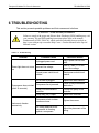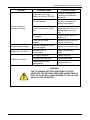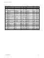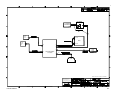
1
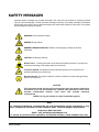
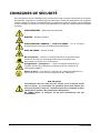
OPERATION MANUAL
MODEL 751
ZERO AIR GENERATOR
© TELEDYNE ADVANCED POLLUTION INSTRUMENTATION
9480 CARROLL PARK DRIVE
SAN DIEGO, CA 92121-5201
USA
Toll-free Phone:
Phone:
Fax:
Email:
Website:
Copyright 2014
Teledyne Advanced Pollution Instrumentation
800-324-5190
858-657-9800
858-657-9816
[email protected]
http://www.teledyne-api.com/
07836A DCN6832
10 January 2014
ABOUT THIS MANUAL
This Model 751 Zero Air Generator operation manual is comprised of multiple documents as
listed below.
Part No.
Rev
Name/Description
07836
A
Model 751 User Manual (this manual)
07840
A
Model 751 Spare Parts List (in Appendix A of this manual)
078380100
A
Model 751 Interconnect List (in Appendix B of this manual)
07838
A
Model 751 Interconnect Diagram (in Appendix B of this manual)
NOTE
Read this manual in its entirety before making any attempt to operate the instrument.
REVISION HISTORY
751 Manual , PN 07836
Date
Rev DCN
10 Jan 2014
A
6832
07836A DCN6832
Description
Initial Release
i
This page intentionally left blank.
ii
07836A DCN6832
SAFETY MESSAGES
Important safety messages are provided throughout this manual for the purpose of avoiding personal
injury or instrument damage. Please read these messages carefully. Each safety message is associated
with a safety alert symbol, and are placed throughout this manual and inside the instrument. The symbols
with messages are defined as follows:
WARNING: Electrical Shock Hazard
HAZARD: Strong oxidizer
GENERAL WARNING/CAUTION: Read the accompanying message for specific
information.
CAUTION: Hot Surface Warning
Do Not Touch: Touching some parts of the instrument without protection or proper tools
could result in damage to the part(s) and/or the instrument.
Technician Symbol: All operations marked with this symbol are to be performed by
qualified maintenance personnel only.
Electrical Ground: This symbol inside the instrument marks the central safety grounding
point for the instrument.
CAUTION
This instrument should only be used for the purpose and in the manner described in
this manual. If you use this instrument in a manner other than that for which it was
intended, unpredictable behavior could ensue with possible hazardous
consequences.
NEVER use any gas analyzer to sample combustible gas(es)!
Note
For Technical Assistance regarding the use and maintenance of this instrument or any
other Teledyne API product, contact Teledyne API’s Technical Support Department:
Telephone: 800-324-5190
Email: [email protected]
or access any of the service options on our website at http://www.teledyne-api.com/
07836A DCN6832
iii
CONSIGNES DE SÉCURITÉ
Des consignes de sécurité importantes sont fournies tout au long du présent manuel dans le but d’éviter
des blessures corporelles ou d’endommager les instruments. Veuillez lire attentivement ces consignes.
Chaque consigne de sécurité est représentée par un pictogramme d’alerte de sécurité; ces pictogrammes
se retrouvent dans ce manuel et à l’intérieur des instruments. Les symboles correspondent aux consignes
suivantes :
AVERTISSEMENT : Risque de choc électrique
DANGER : Oxydant puissant
AVERTISSEMENT GÉNÉRAL / MISE EN GARDE : Lire la consigne
complémentaire pour des renseignements spécifiques
MISE EN GARDE : Surface chaude
Ne pas toucher : Toucher à certaines parties de l’instrument sans
protection ou sans les outils appropriés pourrait entraîner des
dommages aux pièces ou à l’instrument.
Pictogramme « technicien » : Toutes les opérations portant ce
symbole doivent être effectuées uniquement par du personnel de
maintenance qualifié.
Mise à la terre : Ce symbole à l’intérieur de l’instrument détermine le
point central de la mise à la terre sécuritaire de l’instrument.
MISE EN GARDE
Cet instrument doit être utilisé aux fins décrites et de la manière décrite
dans ce manuel. Si vous utilisez cet instrument d’une autre manière que
celle pour laquelle il a été prévu, l’instrument pourrait se comporter de façon
imprévisible et entraîner des conséquences dangereuses.
NE JAMAIS utiliser un analyseur de gaz pour échantillonner des gaz
combustibles!
iv
07836A DCN6832
WARRANTY
WARRANTY POLICY (02024G)
Teledyne Advanced Pollution Instrumentation (TAPI), a business unit of Teledyne
Instruments, Inc., provides that:
Prior to shipment, TAPI equipment is thoroughly inspected and tested. Should equipment
failure occur, TAPI assures its customers that prompt service and support will be available.
COVERAGE
After the warranty period and throughout the equipment lifetime, TAPI stands ready to
provide on-site or in-plant service at reasonable rates similar to those of other manufacturers
in the industry. All maintenance and the first level of field troubleshooting are to be
performed by the customer.
NON-TAPI MANUFACTURED EQUIPMENT
Equipment provided but not manufactured by TAPI is warranted and will be repaired to the
extent and according to the current terms and conditions of the respective equipment
manufacturer’s warranty.
Product Return
All units or components returned to Teledyne API should be properly packed for
handling and returned freight prepaid to the nearest designated Service Center. After the
repair, the equipment will be returned, freight prepaid.
The complete Terms and Conditions of Sale can be reviewed at http://www.teledyneapi.com/terms_and_conditions.asp
CAUTION – Avoid Warranty Invalidation
Failure to comply with proper anti-Electro-Static Discharge (ESD) handling and
packing instructions and Return Merchandise Authorization (RMA) procedures when
returning parts for repair or calibration may void your warranty. For anti-ESD
handling and packing instructions please refer to the manual, Fundamentals of ESD,
PN 04786, in its “Packing Components for Return to Teledyne API’s Customer
Service” section. The manual can be downloaded from our website at
http://www.teledyne-api.com under Help Center > Product Manuals in the Special
Manuals section. RMA procedures are under Help Center > Return Authorization.
07836A DCN6832
v
This page intentionally left blank.
vi
07836A DCN6832
TABLE OF CONTENTS
ABOUT THIS MANUAL ........................................................................................................... I
REVISION HISTORY............................................................................................................... I
SAFETY MESSAGES ............................................................................................................. III
1 INTRODUCTION ......................................................................................... 9
1.1
1.2
PREFACE ................................................................................................................... 9
MODEL 751 FEATURES ............................................................................................... 9
2 SPECIFICATIONS AND APPROVALS ..................................................... 10
2.1 SPECIFICATIONS....................................................................................................... 10
2.2 APPROVALS AND CERTIFICATIONS ............................................................................. 11
2.2.1 Safety .............................................................................................................. 11
2.2.2 EMC ................................................................................................................. 11
3 GETTING STARTED................................................................................ 3-1
3.1 UNPACKING ............................................................................................................ 3-1
3.2 INSTALLATION ......................................................................................................... 3-1
3.3 INSTRUMENT PANEL ................................................................................................ 3-2
3.4 ELECTRICAL AND PNEUMATIC CONNECTIONS ............................................................. 3-3
3.4.1 ELECTRICAL.................................................................................................. 3-3
3.4.2 PNEUMATICS ................................................................................................ 3-3
3.5 POWER-UP............................................................................................................. 3-3
3.6 STORAGE AND TRANSPORTATION ............................................................................. 3-4
3.7 EXPENDABLE KITS (OPT 42A) ................................................................................. 3-1
3.8 SILICA GEL KITS (OPT 42B&C) ............................................................................... 3-1
3.9 FLOW RESTRICTOR (OPT 72B) ............................................................................... 3-1
4 OPERATION ............................................................................................ 4-1
4.1 OVERVIEW .............................................................................................................. 4-1
4.2.1 Intake Filter ..................................................................................................... 4-4
4.2.2 Compressor .................................................................................................... 4-4
4.2.3 Cooling Coil .................................................................................................... 4-5
4.2.4 Pressure Relief Valve ..................................................................................... 4-5
4.2.5 Water Trap ...................................................................................................... 4-5
4.2.6 Water Drain Valve .......................................................................................... 4-5
4.2.7 Silica Gel Desiccant ........................................................................................ 4-5
4.2.8 Pressure Regulator ......................................................................................... 4-6
4.2.9 NO Scrubber ................................................................................................... 4-6
4.2.10 Charcoal Scrubber ....................................................................................... 4-6
4.2.11 Optional Carbon Monoxide (CO) Scrubber .................................................. 4-6
4.2.12 Final Filter .................................................................................................... 4-6
4.2.13 Pressure Gauge........................................................................................... 4-6
4.2.14 Controller ..................................................................................................... 4-7
4.2.15 Front Panel Indicator Lights ......................................................................... 4-8
07836A DCN6832
vii
4.2.16
Dew Point Sensor ........................................................................................ 4-8
5 MAINTENANCE ....................................................................................... 5-1
5.1 SCHEDULE .............................................................................................................. 5-1
5.2 CLEANING............................................................................................................... 5-2
5.3 CHECKING THE TUBING ........................................................................................... 5-2
5.4 REPLACING THE CHARCOAL SCRUBBER MEDIA .......................................................... 5-2
5.5 REPLACING THE NO - NO2 SCRUBBER MEDIA ........................................................... 5-3
5.6 REPLACING THE OPTIONAL CO SCRUBBER ............................................................... 5-4
5.7 REPLACING THE SILICA GEL DESICCANT ................................................................... 5-4
5.8 LEAK CHECK ........................................................................................................... 5-5
5.9 FILTER REPLACEMENT ............................................................................................. 5-6
5.9.1 Intake Filter ..................................................................................................... 5-6
5.9.2 Final Filter ....................................................................................................... 5-6
6 TROUBLESHOOTING ............................................................................. 6-1
APPENDIX A - SPARE PARTS ..........................................................................................A-1
APPENDIX B - SCHEMATICS ...........................................................................................B-1
LIST OF FIGURES
FIGURE 3-1:
FIGURE 4-1:
FIGURE 4-2:
FIGURE 4-3:
FIGURE 4-4:
MODEL 751 STARTUP CONNECTIONS ................................................................................... 3-2
PNEUMATIC DIAGRAM .......................................................................................................... 4-2
INSTRUMENT PLAN VIEW ..................................................................................................... 4-3
INSTRUMENT PANEL ............................................................................................................. 4-4
CONTROL BOARD LAYOUT ................................................................................................... 4-7
LIST OF TABLES
TABLE 2-1:
TABLE 4-1:
TABLE 5-1:
TABLE 6-1:
viii
SPECIFICATIONS ...................................................................................................................... 10
POWER AND DEW POINT CONDITION INDICATORS ................................................................. 4-8
MAINTENANCE SCHEDULE..................................................................................................... 5-1
TROUBLESHOOTING ............................................................................................................... 6-1
07836A DCN6832
1 INTRODUCTION
1.1 Preface
The Model 751 (or 751) is an excellent source of clean, dry air for dilution calibrators. It
also may be used as a source of purge air for permeation tube ovens, zero air for
ozone generators. The 751 has an oil-free and diaphragm-free pump that pushes the
air through silica gel desiccant for drying. The pump then routes the dry air through
multiple scrubbers that remove SO2, NO, NO2, O3, H2S, and CO; the outlet air passes
through a final filter to assure a clean, dry, analytical zero air supply.
The silica gel desiccant removes water yielding gas with a dewpoint of less than -20°C
(up to 5 SLPM flow rate) independent of the inlet dewpoint. A microcontroller cycles the
water trap valve to prevent the pump from starting against full head pressure. The 751
is an ideal accessory to the Model 700E Mass Flow Calibrator or Model 702 Single
Point Calibrator as a zero air source for analyzers.
1.2 Model 751 Features
Long life scrubbers for SO2, NO, NO2, O3, H2S, and CO (option)
Automatic water drain
Silica gel desiccant for water removal independent of inlet dewpoint
Source of purge air for permeation tube ovens
Source of zero air for Ozone Generators
07836A DCN6832
9
Specifications and Approvals
Teledyne API Model 751 Zero Air Generator
2 SPECIFICATIONS AND APPROVALS
2.1 Specifications
Table 2-1: Specifications
Parameter
Specification
Output
5 SLPM at 30 psig
Max delivery pressure
30 psig
Dewpoint
< -20 C (until desiccant saturated)
SO2 <0.5 ppb
NO <0.5 ppb
Output Concentration
NO2 <0.5 ppb
O3 <0.5 ppb
CO< 0.025 ppm (requires CO Scrubber option)
Compressor
Single-cylinder, internal long-life, oil-less piston pump
Dimensions
7” x 18.5” x 14” (178 x 470 x 356 mm)
Weight
24 lbs (10.9 kg)
Operating Temp
5-40 C
Power
Environmental Conditions
Typical Power Consumption
110-120 V~, 60 Hz, 4.0 A
105W
220-240 V~, 50 Hz, 3.0 A
130W
Installation Category (Over Voltage Category ) II Pollution Degree 2
Intended for Indoor Use Only at Altitudes 2000m
Mains Supply Voltage Fluctuations not to exceed ± 10% of the
nominal voltage
Transient Over Voltages according to Over Voltage Category II
10
07836A DCN6832
2.2 Approvals and Certifications
The Teledyne-API Model 751 Zero Air Generator was designed, tested and certified for Safety
and Electromagnetic Compatibility (EMC). This section presents the compliance statements for
those requirements and directives. For additional certifications, please contract Technical
Support at 1-800-324-5190 or [email protected].
2.2.1 Safety
IEC/EN 61010-1:2010 (3rd Edition), Safety requirements for electrical equipment for
measurement, control and laboratory use.
CE: 2006/95/EC, Low-Voltage Directive
2.2.2 EMC
IEC/EN 61326-1, Class A Emissions/Industrial Immunity
EN55011 (CISPR 11), Group 1, Class A Emissions
FCC 47 CFR Part 15B, Class A Emissions
CE: 2004/108/EC, Electromagnetic Compatibility Directive
07836A DCN6832
11
Specifications and Approvals
Teledyne API Model 751 Zero Air Generator
This page intentionally left blank.
12
07836A DCN6832
3 GETTING STARTED
This section provides instructions on the proper installation and power-up of the 751.
NOTE
Due to mounting screws through its case, the 751 is not considered waterproof.
3.1 Unpacking
1. Verify that there is no shipping damage. If there are signs of damage, immediately
advise the shipper, then Teledyne API.
2. Remove the 751 from its shipping carton.
3. Open the lid and check for damage inside.
4. Check the line voltage and frequency label on the instrument to ensure that it
matches the local power source.
3.2 Installation
The basic 751 is a portable, self-contained instrument; there are no installation
instructions other than to ensure adequate support for its weight. However, the
connections must be made to the instrument panel with the lid open (see Section 3.4
for connection instructions).
CAUTION
TO AVOID PERSONAL INJURY OR DAMAGE TO THE INSTRUMENT,
ALWAYS OPERATE THE 751 WITH THE LID OPEN.
07836A DCN6832
3-1
Getting Started
Teledyne API Model 751 Zero Air Generator
3.3 Instrument Panel
Figure 3-1 illustrates the Model 751 instrument layout and key connections for startup.
Figure 3-1: Model 751 Startup Connections
3-2
07836A DCN6832
Teledyne API Model 751 Zero Air Generator
Getting Started
3.4 Electrical and Pneumatic Connections
3.4.1
ELECTRICAL
NOTE
To maintain compliance with EMC standards, it is required that the power cord
length be no greater than 3 meters.
Connect the power cord from the AC input connection to the proper power source.
CAUTION
ENSURE THAT THE POWER CORD IS PROPERLY GROUNDED
AND ADEQUATELY RATED FOR THE SPECIFIED POWER
RATING OF THIS INSTRUMENT (SEE SPECIFICATIONS TABLE).
3.4.2
PNEUMATICS
Make the following pneumatic connections:
DRAIN (1/4” push-to-connect bulkhead union)
Connect 1/4” diameter tubing to the Drain Fitting (refer to Figure 3-1) to avoid the
occasional spurts of water ejecting from the fitting. Ensure the tubing is long
enough that the water ejects outside the instrument.
ZERO AIR OUT (1/4” swage-type bulkhead union)
Connect the ZERO AIR OUT port of the 751 to the INLET fitting of the Model 700
Calibrator with clean 1/4” TFE tubing. Keep this line as short as possible to
minimize pressure drops. The pressure in this line is adjustable, but should
normally be 30 ± 5 psig.
3.5 Power-Up
NOTE:
DO NOT BLOCK THE COOLING FAN (LOCATED BENEATH THE COVER
PANEL); ALWAYS KEEP LID OPEN WHEN INSTRUMENT IS RUNNING.
1. Turn on the instrument panel POWER SWITCH (Figure 3-1).
2. The instrument panel POWER LED should light.
07836A DCN6832
3-3
Getting Started
Teledyne API Model 751 Zero Air Generator
3. The cooling fan should start immediately.
4. The compressor should start after a few seconds delay. The delay is to allow the
control board to measure the local line frequency.
5. After 30 to 60 seconds, the instrument panel pressure gauge should read 30 psig.
6. When the DEW POINT LED is lit green, it indicates that the 751 is producing clean
dry air.
NOTE
If the 751 has been unused for several days, it may take up to 30 minutes
to achieve final purity and dryness.
3.6 Storage and Transportation
If the 751 will not be used for an extended period of time or will be transported, the
following procedure applies:
1. Turn off the 751.
2. Wait approximately 1 minute.
3. Turn on the 751. The water drain valve will switch into the open position and vent
any accumulated water through the water drain. (Standing H2O will cause corrosion)
4. Turn the 751 off.
This shut down process will vent any water that has accumulated in the coalescing
filter. It will prevent this water from passing into the 751 in the event that the instrument
is inverted during storage or shipment.
3-4
07836A DCN6832
3.7 Expendable Kits (OPT 42A)
A one-year supply of scrubber media and outlet filter are available from Teledyne API
as Option 42A. Refer to Appendix B for a list of expendables.
3.8 Silica Gel Kits (OPT 42B&C)
An additional supply of Silica Gel media is available from Teledyne API as Option 42B.
A spare Silica Gel dryer cartridge is available from Teledyne-API as Option 42C. Refer
to Appendix B for a list of expendables.
3.9 Flow Restrictor (OPT 72B)
A flow restrictor is available in order to run the 751 without a calibrator or other method
of flow restriction. It is connected to the outlet fitting and restricts the air flow to 4 SLPM.
The flow is pressure dependent, which is adjustable by adjusting the pressure regulator.
07836A DCN6832
3-1
Getting Started
Teledyne API Model 751 Zero Air Generator
This page intentionally left blank.
3-2
07836A DCN6832
4
OPERATION
4.1 Overview
The 751 dries and scrubs ambient air to produce zero air. Error! Reference source
not found. illustrates the path of the air being routed through the 751.
First, the compressor draws air in through the inlet filter. At the compressor outlet, the
air is under pressure and hot from the compression. The relative humidity is high as a
result of the high pressure.
The air then is conducted through the cooling coil where heat is removed by transfer to
the cooling fan air. With the high pressure and the temperature reduced to ambient
level, the relative humidity is at its highest. At this point, the air is usually
supersaturated.
From the cooling coil, the damp air passes through a coalescing filter where the excess
water is separated and settles in the bottom of the filter. The controller periodically
opens the solenoid drain valve allowing the water to be expelled through a drain fitting.
This partially dried air flows through a canister of silica gel desiccant, which traps and
absorbs the remaining water and a portion of the other contaminants. The pressure
relief valve may open occasionally and can be loud, but this is a normal part of the
operation for the 751.
As the air leaves the silica gel canister, its pressure is controlled to 30 psig by an air
pressure regulator mounted on the instrument panel. This maintains a constant
pressure at the calibrator inlet and is displayed by the pressure gauge on the 751
instrument panel.
For a final clean-up, the dry, regulated air enters the specific scrubbers as follows:
1. The NO scrubber where NO is oxidized to NO2.
2. The activated charcoal scrubber where the NO2, O3, SO2 and H2S are absorbed.
3. The optional CO scrubber, where CO is catalytically oxidized to CO2.
4. The clean, dry air passes through a fine particulate filter and leaves the 751 through
the instrument panel bulkhead union (Zero Air Out).
07836A DCN6832
4-1
Operation
Teledyne API Model 751 Zero Air Generator
751 Chassis
Pressure Relief
Valve
Inlet Filter
Condenser
Coalescer
“AIR IN”
5 LPM Pump
Pressure
Regulator
Drain Valve
30
Pressure
Gauge
0
Purafil Scrubber
DFU
Filter
Charcoal Scrubber
“ZERO AIR OUT”
CO Scrubber *
Dewpoint
Sensor
Silica Gel Desiccant
“DRAIN OUT”
60
* Optional Equipment
Figure 4-1: Pneumatic Diagram
4-2
07836A DCN6832
Teledyne API Model 751 Zero Air Generator
Operation
Figure 4-2: Instrument Plan View
07836A DCN6832
4-3
Operation
Teledyne API Model 751 Zero Air Generator
Figure 4-3: Instrument Panel
4.2 Components
This section describes the main components of the 751.
4.2.1 Intake Filter
The intake filter is a serviceable assembly that houses a disposable paper filter
element. Section 5 provides maintenance instructions.
4.2.2 Compressor
The compressor is a single-cylinder oscillating piston type driven by a split capacitor
AC motor. The compressor is dry; that is, there are no lubricants which can
contaminate the compressed air. The pistons are sealed by flexible TFE piston rings,
and after a short run-in period to seat the rings, should last for years. There are no
diaphragms.
The compressor is mounted on a sub-plate which is supported on four, tuned vibration
isolators.
4-4
07836A DCN6832
Teledyne API Model 751 Zero Air Generator
Operation
4.2.3 Cooling Coil
The cooling coil consists of several turns of copper tubing coiled to form a cylinder
through which the cooling fan blows outside air.
4.2.4 Pressure Relief Valve
The pressure relief valve is a device designed to limit the maximum pressure to which
the 751 can be subjected. It is set to open at 75-80 psig. The valve may open and make
a hissing sound. This is normal operation and does not mean there is a problem with
the unit.
CAUTION
DO NOT ADJUST THE RELIEF VALVE.
4.2.5 Water Trap
The water trap is a coalescing type. Supersaturated air enters the trap and is rapidly
swirled causing the water droplets to deposit on a membrane where the drops coalesce
and gather in a puddle at the bottom of the filter bowl.
4.2.6 Water Drain Valve
Accumulated water is drained from the filter through a stainless steel solenoid-operated
valve. The valve is sequenced by the controller and is pulsed open every minute to
remove water from the filter bowl.
CAUTION
THE WATER/AIR SPRAY LEAVING THE DRAIN FITTING SPURTS AT
A HIGH VELOCITY AND MUST BE CONDUCTED THROUGH A
LENGTH OF TUBING AWAY FROM ANY SENSITIVE COMPONENTS.
The operation cycle has been preset at the factory and is not adjustable.
4.2.7 Silica Gel Desiccant
The silica gel desiccant absorbs the remaining moisture from the air. Silica gel has a
finite life and changes color as it becomes saturated. We recommend that it be
replaced when the dewpoint indicator changes from green to yellow.
07836A DCN6832
4-5
Operation
Teledyne API Model 751 Zero Air Generator
4.2.8 Pressure Regulator
The pressure regulator is set at 30 psig at the factory except for customized units.
Should adjustment be desired, the regulator is accessible on the instrument panel. The
adjustment knob has a push-pull locking ring which should be reengaged after making
an adjustment to prevent the knob from turning under vibration.
When the 751 is used with the Teledyne API Model 700 Calibrator, the pressure should
be between 28 and 32 psig. The Model 700 calibrator requires that its air source be
stable and not subject to compressor-induced pressure surges or pressure variations
with flow.
4.2.9 NO Scrubber
The NO scrubber uses Purafil® to oxidize NO to NO2. Purafil® has a finite life and we
recommend that it be replaced annually or sooner if the level of NO in the air is high.
4.2.10 Charcoal Scrubber
Activated charcoal removes NO2, O3, SO2 and H2S. The charcoal should be replaced
annually or sooner if there are high atmospheric levels of these contaminants, or if the
calibrator zero air shows signs of a positive drift.
4.2.11 Optional Carbon Monoxide (CO) Scrubber
The CO scrubber catalytically oxidizes CO to CO2. The catalyst is proprietary and
operates at room temperature; theoretically, it should never need changing. However, if
in the event it were to become contaminated or poisoned, we recommend that the
scrubber be replaced.
4.2.12 Final Filter
The final filter, located adjacent to the instrument panel retains any particulates
released by the 751. The filter rating is 99.99% removal of 0.1 micron particles. If the
filter becomes restricted, it should be replaced.
4.2.13 Pressure Gauge
The pressure gauge shows the regulated air pressure available to a calibrator. The
gauge will usually indicate 30 psig. If the flow demand from the calibrator changes, the
regulator may need to be adjusted to display the correct pressure on the gauge. It is
normal for the gauge needle to not rest at zero when the system is not under pressure.
4-6
07836A DCN6832
Teledyne API Model 751 Zero Air Generator
Operation
4.2.14 Controller
WARNING
DANGEROUS VOLTAGES EXIST ON THE CONTROLLER BOARD.
All functions of the 751 are managed by the 751 Control Board (Figure 4-4). The control
board provides connections for all switched and non-switched AC components, AC
input, and the instrument panel power switch/circuit breaker.
Switched components include the water drain valve, and the relief valve.
Non-switched components include the fan, the LED board, and the pump.
Provision for 120V/240V AC power is via a jumper plug/autotransformer connector (J2).
All connections are made by quick release electrical connectors to aid in servicing.
Refer to Figure 4-4 for the layout and to Appendix B for the interconnect and other
drawings.
The 751 control board is microcontroller based, and all timing is derived from the AC
line. It automatically senses the line frequency (50/60 Hz) and cycles the water drain
solenoid valve and monitors the dewpoint sensor.
LED D13 (Figure 4-4) flashes at 1 second intervals as an indication that the controller is
functioning, and a watchdog timer is enabled to prevent any power line disturbances
from halting the processor.
Figure 4-4: Control Board Layout
07836A DCN6832
4-7
Operation
Teledyne API Model 751 Zero Air Generator
4.2.15 Front Panel Indicator Lights
Multicolor indicator lights for both the power state and dewpoint state relay diagnostic
information and instrument mode to the user.
Table 4-1: Power and Dew Point Condition Indicators
Power
Indicator
Dew Point
Indicator
Instrument State
Green
Green
Power ON, Dewpoint GOOD
Green
Yellow
Power ON, Dewpoint CAUTION
Green
Red
Power ON, Dewpoint BAD
Green
Red-Flashing
Power ON, Dewpoint CRITICAL
Red-Flashing
Yellow
Temperature Fault.
Red-Flashing
Red
Dew Point Fault.
4.2.16 Dew Point Sensor
The dewpoint sensor ensures that the 751 maintains a dewpoint less than -20°C by
monitoring the condition of the silica gel output. When the dewpoint rises above the
warning setpoint, the DEWPOINT LED will change color. See Error! Reference source
not found..
4-8
07836A DCN6832
5 MAINTENANCE
5.1 Schedule
WARNING
There are high voltages present while the 751 is plugged in.
The operations outlined in this section are to be performed by
qualified maintenance personnel only.
Before performing any maintenance, cycle the power on/off and drain any water that
may be present (refer to instructions for “Storage and Transportation” in Section 3.6).
Table 5-1 presents the maintenance schedule.
Table 5-1: Maintenance Schedule
Item
Recommended
Frequency
Refer to Section
Charcoal
Scrubber
Purafil
Annually
Annually
5.4
5.5
CO Scrubber
Option
Silica Gel
Intake and
Final Filters
When
Contaminated
5.6
When
Contaminated
5.7
When
Contaminated
5.9
January
February
March
April
May
Month
June
July
August
September
October
November
December
07836A DCN6832
5-1
MAINTENANCE
Teledyne API Model 751 Zero Air Generator
5.2 Cleaning
1. Occasionally, depending upon the local conditions, check the inside of the 751
for excessive dirt or dust.
2. Particularly, check the cooling fan, cooling coil and compressor fan inlet.
3. Remove any dirt or dust with a vacuum cleaner.
Do not use an air jet. This will only redistribute the dirt and will not remove it.
5.3 Checking The Tubing
1. Under the vibration of the compressor, it is possible for some parts of the TFE
tubing to abrade against nearby objects. This is most likely to occur with the
tubing directly attached to the compressor.
2. Check to see if any signs of abrasion are present, and, if so, re-dress the tubing.
3. If any section of tubing appears to be heavily abraded, remove and replace it.
CAUTION
DO NOT LOOSEN ANY TUBING CONNECTION WHILE THE 751 IS
RUNNING.
CAUTION
BEFORE WORKING ON THE 751 PLUMBING TURN OFF THE 751,
WAIT FOR THE PRESSURE GAUGE TO READ ZERO. (THIS MAY
REQUIRE THAT YOU LOOSEN THE INSTRUMENT PANEL
BULKHEAD UNION TO ALLOW THE AIR TO BLEED AWAY.)
WARNING
EVEN THOUGH THE INSTRUMENT PANEL POWER SWITCH IS
OFF, THERE IS LINE VOLTAGE PRESENT AT THE POWER ENTRY
TERMINALS, POWER SWITCH TERMINALS AND ON THE
CONTROL BOARD. FOR ADDED SAFETY, REMOVE THE POWER
CORD FROM THE INSTRUMENT PANEL RECEPTACLE.
5.4 Replacing the Charcoal Scrubber Media
Before emptying the used charcoal, wearing a dust mask could be helpful as a
preventive measure since it is possible that some charcoal dust may rise when emptying
and refilling the canister.
5-2
07836A DCN6832
Teledyne API Model 751 Zero Air Generator
MAINTENANCE
NOTE
The push-to-connect fittings allow quick tubing connection and disconnection
using an internal grasping ring and O-ring to keep the tubing secure. To
disconnect, push on the white release ring and pull the tubing straight out of the
fitting. To reinstall, insert the tubing into the fitting until it is fully seated.
1. Turn off the 751 and wait for the pressure to go to zero.
2. Open the instrument panel, or remove the top cover.
3. Remove the 1/4” tubing connected to the top of the scrubber canister.
4. Release the fastening strap to free the canister.
5. Remove the 1/4” tubing connected to the bottom of the canister.
6. Unscrew the cap of the canister.
7. Remove the pad from the top of the canister.
8. Pour out the charcoal and dispose of it properly.
9. Refill the canister with fresh charcoal, up to 3/8” to 1/4” from the top. Rap the sides
of the canister gently to settle the charcoal and add more as necessary.
10. Replace the pad on top of the charcoal.
11. Wipe any charcoal dust from the top edge of the canister. This is the surface which
seals against the washer.
12. Check that the washer is in place in the cap.
13. Replace the cap and tighten it “hand-tight”.
14. Reconnect the lower 1/4” tube connection.
15. Reattach the canister with the fastening strap.
16. Reconnect the upper 1/4” tube.
17. After the compressor is turned on, it may be wise to check the scrubber for leaks
using a commercial soap solution leak finder.
5.5 Replacing the NO - NO2 Scrubber Media
This procedure is identical to the charcoal scrubber replacement procedure except that
the canister should be refilled with Purafil .
NOTE
After replacing the material in these scrubbers it can take up to 48 hours for
the material to dry out before the 751 is functioning optimally.
07836A DCN6832
5-3
MAINTENANCE
Teledyne API Model 751 Zero Air Generator
5.6 Replacing The Optional CO Scrubber
The CO scrubber is attached to a bracket between the NO-NO2 scrubber and the
silica gel canister. This is not a heated scrubber. It is secured with four screws
through the body of the scrubber into the bracket.
1. Turn off power and unplug the 751.
2. Remove the four screws to remove the scrubber.
CAUTION
THE SCRUBBER MAY BE HOT.
3. With a 9/16” wrench, remove the two unions from the top of the scrubber
cartridge.
4. Pick out the retaining screens.
5. Shake out the catalyst beads and dispose. No special disposal methods
required.
6. Pour in new catalyst to 1/2” from the top of the bores. Tap the cartridge sides
gently to settle the beads and top up to the 1/2” level.
7. Return the retainer screens.
8. Replace the TFE tape on the two unions and replace the unions in the cartridge.
9. Reassemble the scrubber, replace it in the chassis and reconnect the tubing and
receptacle.
10. Turn on the 751 and perform a leak check using soap solution.
5.7 Replacing the Silica Gel Desiccant
1. Turn off the power and wait for the pressure to go to zero.
2. Remove the tubes attached to the canister by pressing the metal button to
unlatch them.
3. Remove canister from the two fastening straps.
4. On spring end of canister, carefully unscrew lid with control to prevent sudden
release of spring.
5. Remove the spring, the metal grate, and the filter from the canister.
6. Dispose of the used silica gel in accordance with local regulation.
5-4
07836A DCN6832
Teledyne API Model 751 Zero Air Generator
MAINTENANCE
7. Refill the canister with a new batch of silica gel (see Spare Parts Kits in Appendix
B).
8. Return the filter first, then the metal grate, and the spring to the canister in same
order.
9. Screw lid back on the canister.
10. Resecure the canister with fastening straps, with the spring end oriented toward
the instrument panel.
11. Reattach the tubes, latching them properly in place.
12. Turn on the 751.
5.8 Leak Check
WARNING
ENSURE TO DISCONNECT THE POWER CORD FROM THE
POWER SOURCE PRIOR TO PERFORMING ANY LEAK CHECK
PROCEDURE.
.
1. Power off the unit and unplug the power cord.
2. Cap the zero out fitting and the drain port fitting.
3. Disconnect the line to the dewpoint sensor manifold and cap it.
4. Plug in the power cord, power on the unit, and allow it to run for one minute (until
it’s pressurized).
5. Turn off the power switch and wait five minutes. The reading on the instrument
panel pressure gauge should not change.
NOTE
This procedure checks the majority of the components and fittings. If you
believe that there is still a leak, please contact Technical Support:
(858) 657-9800.
07836A DCN6832
5-5
MAINTENANCE
Teledyne API Model 751 Zero Air Generator
5.9 Filter Replacement
5.9.1 Intake Filter
To replace the filter element housed in the serviceable Intake Filter assembly (Figure
4-2):
1. Turn the filter cap counter-clockwise and remove from the filter housing.
2. Replace the used filter element with a new filter element (Teledyne API P/N
FL16).
3. Return the filter cap to the filter housing and secure in place with a clockwise
turn.
5.9.2 Final Filter
To replace the disposable Final filter unit (Figure 4-2):
1. Remove the disposable filter unit (DFU) from the retainer clip.
2. Release the tubing at each end of the DFU by pressing the spring-loaded quickconnects toward the DFU and pulling the tubing away.
3. Dispose the used DFU.
4. Reinsert the tubing into each end of the new DFU (Teledyne API P/N FL50),
pushing in tightly to secure.
5. Secure the new filter unit into the retainer clip.
5-6
07836A DCN6832
Teledyne API Model 751 Zero Air Generator
TROUBLESHOOTING
6 TROUBLESHOOTING
This section presents possible problems and their causes and solutions.
CAUTION – Avoid Warranty Invalidation
Failure to comply with proper anti-Electro-Static Discharge (ESD) handling may void
your warranty. For anti-ESD handling instructions please refer to the manual,
Fundamentals of ESD, PN 04786, which can be downloaded from our website at
http://www.teledyne-api.com under Help Center > Product Manuals in the Special
Manuals section.
Table 6-1: Troubleshooting
Problem
Power light does not come
on.
Compressor does not start
(after 10 seconds).
Instrument vibrates
excessively.
07836A DCN6832
Probable Cause
Corrective Action
Unplugged power cord.
Plug in power cord at both
ends.
Incorrect line voltage.
Refer to Table 3-1 for the
correct line voltage.
Tripped power switch/circuit
breaker.
Reset power switch/circuit
breaker.
AIR IN filter is plugged.
Replace the filter element.
Compressor fan is jammed.
Check for any mechanical
obstruction.
Pump is not connected to
controller.
Connect the pump to the
controller.
Pump relay (K4) is open.
Replace the controller.
Compressor shock isolator
screws are loose.
Tighten the screws.
The tubing attached to the
compressor is vibrating
against a component.
Adjust the placement of the
tubing.
6-1
Teledyne API Model 751 Zero Air Generator
Problem
Probable Cause
Air demand to too high.
Maximum air flow is 5 SLPM.
Air Inlet impeded.
Pressure does not
increase to 30 psig.
Pressure regulator is set too
low.
Corrective Action
No action. Pressure will
increase as flow demand
decreases.
Remove the inlet filter and
check for impediment or
replace filter element.
Adjust the pressure on the
instrument panel. (Please see
Warning Note at end of this
table).
Air leakage.
Check for leaks. Refer to
Section 5.8.
Pump has low output
pressure.
Rebuild pump (see sticker on
pump for rebuild kit PN).
Output pressure surges.
Pressure regulator is set too
high and pegged.
Adjust pressure regulator down.
Output air is not “Zero”.
Scrubbers may be
contaminated.
Replace the scrubber
media.
Silica gel is saturated.
Replace silica gel.
Scrubbers are saturated.
Dry scrubber media.
Dewpoint sensor tube
disconnected.
Verify connection.
Output air is not dry.
Note:
WARNING
THE 751 NOMINAL DELIVERY PRESSURE IS 30 PSIG.
NEVER SET THE DELIVERY PRESSURE HIGHER THAN 35
PSIG. TO DO SO MAY CAUSE DAMAGE TO THE 751 AND
INJURY TO THE OPERATOR.
6-2
07836A DCN6832
APPENDIX A - SPARE PARTS
Note
Use of replacement parts other than those supplied by T-API may result in
non-compliance with European standard EN 61010-1.
Note
Due to the dynamic nature of part numbers, please refer to the Website at
http://www.teledyne-api.com or call Customer Service at 800-324-5190for more
recent updates to part numbers.
07836A DCN6832
A-1
This page intentionally left blank.
A-2
07836A DCN6832
078400000
751 SPARE PARTS LIST
PART NUMBER
005960000
005970000
006900100
018490000
040370000
043910100
057270000
077830200
078580000
078610000
078650000
078650100
078970000
FL0000007
FL0000015
FL0000016
FL0000050
HW0000439
PU0000069
DESCRIPTION
MEDIA, ACTIVATED CHARCOAL KIT
MEDIA, PURAFIL KIT
FELT PADS FOR SCRUBBER CANISTERS
PRESSURE GAGE
CO SCRUBBER ASSEMBLY
MEDIA, SILICA GEL DESICCANT KIT
GASKET FOR SCRUBBER CANISTERS
PCA, CONTROL BOARD, 751
ASSY, WATER DROP VALVE 751
ASSY, 12VDC FAN 751
PUMP ASSY, 115V/60HZ, 751
PUMP ASSY, 230V/50HZ, 751
ASSY, DRIER CANISTER, 751
FILTER, COALESCING
FILTER, INTAKE, 751
REPLACEMENT INTAKE FILTER ELEMENT
FILTER, DFU, KYNAR
BULKHEAD SCRUBBER MOUNT
REBUILD KIT, PUMP, 751
07836A DCN6832
Revision A
A-3
This page intentionally left blank.
A-4
07836A DCN6832
APPENDIX B - SCHEMATICS
07836A DCN6832
B-1
This page intentionally left blank.
B-2
07836A DCN6832
Interconnect List 751, 078380100A
Revision
A
Cable Part
#
Description
Production Release
Signal
Checked
RH
CONNECTION FROM
Assembly
PN
077940100 Cbl Assy, Front Panel LED Indicator, 751X
PWR RED LED
Front Panel LED Board
PWR GREEN LED
Front Panel LED Board
RH RED LED
Front Panel LED Board
GND
Front Panel LED Board
GND
Front Panel LED Board
RH GREEN LED
Front Panel LED Board
078580200 Assy, Water Drop Valve, 751
+12V RET
Water Drop Valve
+12V
Water Drop Valve
078610000 Assy, 12VDC Fan, T701X/751X
+12V RET
12VDC Fan
+12V
12VDC Fan
078650000 Assy, Pump. 115V~, 751
AC Line
Assy, Pump. 115V~
AC Neutral
Assy, Pump. 115V~
Power Gnd
Assy, Pump. 115V~
078650100 Assy, Pump. 230V~, 751
AC Line
Assy, Pump. 230V~
AC Neutral
Assy, Pump. 230V~
Power Gnd
Assy, Pump. 230V~
078720000 Cbl Assy, AC Power, 751X
AC Line
Power Entry
AC Neutral
Power Entry
Power Gnd
Power Entry
Power Gnd
Power Entry
AC Line Switched
Power Switch
AC Neutral Switched
Power Switch
Power Gnd
Power Entry
079910000 Cbl Assy, Power Supply, 751X
AC Line
Power Supply
AC Neutral
Power Supply
+12V
Power Supply
+12V RET
Power Supply
07836A DCN6832
Date
10/6/2013
J/P
Pin
077890000
077890000
077890000
077890000
077890000
077890000
J1
J1
J1
J1
J1
J1
1
2
7
4
3
6
Control Board
Control Board
Control Board
Control Board
Control Board
Control Board
078580000
078580000
P16
P16
1
2
078610000
078610000
P7
P7
CONNECTION TO
PN
J/P
Pin
077830000
077830000
077830000
077830000
077830000
077830000
J11
J11
J11
J11
J11
J11
1
2
3
4
5
6
Control Board
Control Board
077830000
077830000
J16
J16
1
2
1
2
Control Board
Control Board
077830000
077830000
J7
J7
1
2
077990000
077990000
077990000
L
N
G
Control Board
Control Board
Control Board
077830000
077830000
077830000
J8
J8
J8
1
2
3
077990100
077990100
077990100
L1 Control Board
L2 Control Board
G Control Board
077830000
077830000
077830000
J8
J8
J8
1
2
3
CN0000073
CN0000073
CN0000073
CN0000073
SW0000069
SW0000069
CN0000073
L
N
G
G
L
N
G
Power Switch
Power Switch
Shield
Chassis Gnd
Control Board
Control Board
Control Board
SW0000069
SW0000069
SW0000069
077830000
077830000
077830000
J1
J1
J1
3
6
2
1
3
1
3
Control Board
Control Board
Control Board
Control Board
077830000
077830000
077830000
077830000
J2
J2
J2
J2
1
5
4
8
PS0000048
PS0000048
PS0000048
PS0000048
J1-AC
J1-AC
J2-DC
J2-DC
Assembly
DCN
6768
L
N
B-3
This page intentionally left blank.
B-4
07836A DCN6832
AC POWER
ENTRANCE
WATER
DROP
VALVE
J1
AC POWER
SWITCH
J1 AC
PS48
FRONT
PANEL
LED
J2 DC
J1
J2
J16
J1
FAN
FA10
J7
J11
CONTROL BOARD
077830000
751
J8
PUMP
Printed Documents are Uncontrolled
The information hereon is the property of
API and is submitted in strictest
confidence for reference only.
Unauthorized use by anyone for any othe
rpurposese is prohibited. This document
or any information contained in it may be
duplicated without proper authorization.
07836A DCN6832
ADVANCED POLLUTION INSTRUMENTATION
Everywhere
look
B-5