1
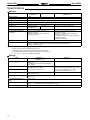
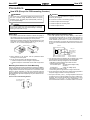
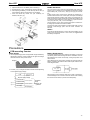
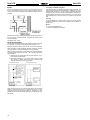
Self-powered Tachometer
H7ER
Revolutions displayed up to five digits.
Dual revolution display according to encoder
resolution used; 1000 s–1/1000 min–1 or 1000.0 s–1
/1000.0 min–1
Switchable dual revolution display type available
(-NV1 models); extended up to 10000 min–1
Ordering Information
Tachometers
Count input
Cou
pu
Max. revolutions displayed (applicable encoder resolution)
Display
sp ay
1000 s–1 (1 pulse/rev.),
1000 min–1 (60 pulse/rev.)
Light-gray body
1000.0 s–1 (10 pulse/rev.),
1000.0 min–1 (600 pulse/rev.) ←→
10000 min–1 (60 pulse/rev.) (switchable)
Black body
Light-gray body
Black body
PNP/NPN
universal DC
lt
i
t
voltage
input
7-segment LCD
with backlight
H7ER-NV-H
H7ER-NV-BH
H7ER-NV1-H
H7ER-NV1-BH
7-segment LCD
H7ER-NV
H7ER-NV-B
H7ER-NV1
H7ER-NV1-B
No-voltage input
7-segment LCD
H7ER-N
H7ER-N-B
---
---
Model Number Legend
H7ER - N
1 2
3
4
1. Count Input
None: No-voltage input
V:
PNP/NPN universal DC voltage input
3. Case Color
None: Light gray
B:
Black
2. Number of Digits
None: 4 digits
1:
5 digits
4. Display
None: 7-segment LCD without backlight
H:
7-segment LCD with backlight
Accessories (Order Separately)
Lithium Battery
Y92S-36
Wire-wrap Terminal (Set of two Terminals)
Y92S-37
Flush
us Mounting
ou
g Adapter
dap e
26 mm
24.8 mm
45 mm
48.8 mm
Y92F-75
Y92F-77B
19
New H7ER
New H7ER
Specifications
General
Item
H7ER-NV-j
H7ER-NV-jH
H7ER-N-j
H7ER-NV1-j
H7ER-NV1-jH
Operating mode
Up type
Mounting method
Flush mounting
External connections
Screw terminals, Wire-wrap Terminals (see note 3)
Display
7-segment LCD with or without backlight (character height: 8.6 mm) (see note 4)
Number of digits
4
Count input
PNP/NPN universal
DC voltage input
Max. counting speed
1 kHz
10 Hz
Max. revolutions displayed
(see note 5)
1,000 s–1 (When encoder resolution of
1 pulse/rev is used.)
1,000 min–1 (When encoder resolution of
60 pulse/rev is used.)
1,000.0 s–1 (When encoder resolution of
10 pulse/rev is used.)
1,000.0 min–1 (When encoder resolution of
600 pulse/rev is used.)
←→ 10,000 min–1 (When encoder resolution of
60 pulse/rev is used.)
(Switchable with switch)
Attachment
Waterproof packing, flush mounting bracket, revolution unit labels (see note 5)
Approved standard
UL508, CSA C22.2 No.14, Lloyds
Conforms to EN61010-1/IEC61010-1 (Pollution degree2/overvoltage category III)
Conforms to VDE0106/P100
Note:
5
No-voltage input
PNP/NPN universal DC voltage input
1. Reset is not available.
2.
3.
4.
5.
When there is no input, the display will be 0.0 or 0.
Separately ordered Wire-wrap Terminals (Y92S-37) are required.
Only PNP/NPN Universal DC voltage input models have a backlight.
“rpm”, “rps”, “s–1” and “min–1” labels are included.
Ratings
Item
H7ER-NVj-j
H7ER-NVj-jH
H7ER-N-j
Supply voltage
Backlight model: 24 VDC (0.3 W max.) (for
backlight lit)
No-backlight model: Not required (powered by
built-in battery)
Not required (powered by built-in battery)
Count input
High (logic) level: 4.5 to 30 VDC
Low (logic) level: 0 to 2 VDC
(Input impedance: Approx. 4.7 kΩ)
No voltage input
short-circuit
impedance:
Maximum short
circuit im
edance: 10 kΩ max.
Short-circuit residual voltage: 0.5 V max.
Minimum open impedance: 750 kΩ min.
Max. counting speed
4-digit models: 1 kHz
5-digit models: 10 kHz
1 kHz
Minimum signal width
10 Hz: 0.05 ms
1 kHz: 0.5 ms
Terminal screw tightening
torque
0.98 N S m max.
Ambient temperature
Operating:
Storage:
Ambient humidity
Operating: 25% to 85%
Reset input
20
–10°C to 55°C (with no condensation or icing)
–25°C to 65°C (with no condensation or icing)
New H7ER
New H7ER
Characteristics
Item
H7ER-NVj-j
H7ER-NVj-jH
H7ER-N-j
Insulation resistance
100 MΩ min. (at 500 VDC) between
current-carrying metal parts and exposed
non-current-carrying metal parts, and between
the backlight power supply and count input
terminals/reset terminals for backlight models
100 MΩ min. (at 500 VDC) between
current-carrying metal parts and exposed
non-current-carrying metal parts
Dielectric strength
1,000 VAC, 50/60 Hz for 1 min between
current-carrying metal parts and exposed
non-current-carrying metal parts and between
the backlight power supply and count input
terminals/reset terminals for backlight models
1,000 VAC, 50/60 Hz for 1 min between
current-carrying metal parts and exposed
non-current-carrying metal parts
Impulse withstand voltage
4.5 kV between current-carrying terminal and exposed non-current-carrying metal parts
Noise
o se immunity
u y
Square-wave noise generated by noise simulator (pulse width: 100 ns/1 µs, 1-ns rise)
±600 V (Between count input terminals)
±500 V (Between count input terminals)
±480 V (Between the backlight power supply
terminals for backlight models)
Static immunity
±8 kV (malfunction)
Vibration resistance
Malfunction: 0.15-mm single amplitude at 10 to 55 Hz for 10 min each in 3 directions
Destruction: 0.375-mm single amplitude at 10 to 55 Hz for 2 hrs each in 3 directions
Shock resistance
Malfunction: 200 m/s2 3 times each in 6 directions
Destruction: 300 m/s2 3 times each in 6 directions
EMC
(EMI)
Emission Enclosure:
(EMS)
Immunity ESD:
Enclosure rating
Front panel:
Terminal block:
Weight (see note)
No-backlight model: Approx. 60 g
Backlight model: Approx. 65 g
Note:
EN50081-1
EN55022 class B
EN50082-2
EN61000-4-2: 4-kV contact discharge (level 2)
8-kV air discharge (level 3)
Immunity RF-interference from AM Radio Waves:
ENV50140:
10 V/m (80 MHz to 1 GHz) (level 3)
Immunity RF-interference from Pulse-modulated Radio Waves:
10 V/m (900 MHz ± 5 MHz) (level 3)
ENV50204:
Immunity Conducted Disturbance: ENV50141:
10 V (0.15 to 80 MHz ) (level 3)
Immunity Burst:
EN61000-4-4: 2-kV power line (level 3)
2-kV I/O signal line (level 4)
IP66, NEMA4 with waterproof packing
IP20
Weight includes waterproof packing and flush mounting bracket.
Reference Value
Item
Battery life
Value
7 years min. with continuous input at
25°C (lithium battery)
Note
The battery life is calculated according to the conditions in the left column
and therefore is not a guaranteed value. Use these value as reference for
maintenance or replacement.
21
New H7ER
New H7ER
Nomenclature
Front view
H7ER
Not used
Counting speed switch
For H7ER-NV1-jj
Bottom view
Counting Speed Switch Settings and Unit Label Application
Model
Counting speed
switch setting
(see note)
Max. revolutions
displayed
Applicable encoder
resolution
Applicable unit
label
10000 min–1
(default setting)
60 pulse/rev.
“min–1” or “rpm”
1000.0 min–1
600 pulse/rev.
“min–1” or “rpm”
1000.0 s–1
10 pulse/rev.
“s–1” or “rps”
1000 min–1
60 pulse/rev.
“min–1” or “rpm”
1000 s–1
1 pulse/rev.
“s–1” or “rps”
Front panel
H7ER-NV1-jj
Terminal block
H7ER-N-j
H7ER-NV-jj
Note:
No setting is
required
Perform switch setting before mounting to a control panel.
Operation
Operating Modes
H7ER Tachometer
Incrementing Operation
Within Unit Time (Up)
Count period
Count period
0.25 s
(1 s)
(1 s)
Internal gate
Display refreshed
Counter reset
Internal count value
Number display
Previous count
value display
Display refreshed
every 1.25 s
22
Display refreshed
every 1.25 s
Refresh
New H7ER
New H7ER
Dimensions
Note:
All units are in millimeters unless otherwise indicated.
H7ER-N
Panel Cutout
Separate mounting
60 min.
45 +0.5
0
22.2 +0.5
0
Dimensions with Flush Mounting Bracket
Joint mounting
(48 Units - 2.5)
+1.0
0
22.2 +0.5
0
Waterproofing is not possible
for joint mounting
•
•
•
When mounting, insert the Counter into
the cutout, insert the adapter from the
back and push in the Counter while
making the gap between the front panel
and the cutout panel as small as
possible. Use screws to secure the
Counter. If waterproofing is desired,
insert the waterproof packing.
When several Counters are installed,
ensure that the ambient temperature
will not exceed specifications.
The appropriate thickness of the panel
is 1 to 5 mm.
23
New H7ER
New H7ER
Installation
Terminal Arrangement
Bottom view: View of the Tachometer rotated horizontally 180°
Backlight Model
No-backlight Model
Backlight
24 VDC
Pulse
input
Pulse
input
Connections
H7ER Tachometer
Note:
Select input transistors according to the following:
Dielectric strength of the collector y 50 V
Leakage current < 100 µA (1 µA for no-voltage input model)
PNP/NPN Universal DC Voltage Input Models With Backlight
No-voltage Input Model
Transistor Input
Transistor Input (Open Collector of an NPN Transistor)
Open collector of
an NPN transistor
or
Open collector of
an NPN transistor
Open collector of
an PNP transistor
Backlight
24 VDC
Input
PNP/NPN Universal DC Voltage Input Models Without Backlight
Transistor Input
Open collector of
an NPN transistor or
Open collector of
an PNP transistor
Input
24
Input
New H7E
New H7E
Accessories (Order Separately)
New H7E (Except for PCB-mounting Counter)
The New H7E models are supplied with a mounting bracket and nut. Additionally, the Flush Mounting Adapters shown here allow the New H7E
models to be fitted to existing panel cutouts.
Y92F-75 Flush Mounting Adapter
for 26 45.3 Rectangular Cutout
Use mounting bracket supplied with the Counter
Panel Cutout
Y92F-77B Flush Mounting Adapter
for 24.8 48.8 Rectangular Cutout
Use mounting bracket supplied with the Counter
Panel cutout
24.8
28.8 24.2 22.2
45.2
48.2
53.8
48.8
4
Y92S-37 Wire-wrap Terminal (Set of Two Terminals)
44.8
Wire-wrap terminal
(1 × 1 mm)
24
22
2
48
When using the Wire-wrap Terminal, be sure to use the correct
wires and peripheral devices. (The correct wires, bits and sleeves
are shown in the table on the right.)
Y92S-36 Lithium Battery (3 V)
Wire
Bit
5
Sleeve
48.5
17.1
Wrapped state
AWG22
2-A
2-B
Normal
AWG24
1-A
1-B
Normal
AWG26
3-A
1-B
Normal
24.5 dia.
7.7
PCB-mounting Counters
XR2A-2801-N 28-pin Socket
Note:
30
When using the Socket, use the PCB processing dimensions previously provided.
New H7E
New H7E
Precautions
New H7E (Except for PCB-mounting Counter)
! WARNING
! Caution
This product has a built-in lithium battery. Do not short-circuit
the + and – terminals, charge, disassemble, deform, or expose
the battery to fire. The battery may explode (break), catch fire,
or cause liquid leakage.
If a voltage other than the rated one is applied, internal elements may be damaged.
Do not use the Counter in the following places:
•
•
•
! Caution
Do not use any battery other than the specified one (Y92S-36).
Using another battery may cause liquid leakage or breakage,
resulting in malfunction or injury.
Before Use
• An insulation sheet has been inserted to maintain the quality of
Locations subject to direct sunlight.
Locations subject to corrosive gases.
Locations subject to dust.
Reset Input and Count/Timer Input
• The H7E operates using its built-in Battery.
If the H7E is
connected to a device that has +V and OUT terminals that are
connected with a diode as shown in the circuit diagram, the
circuit indicated by the arrow 1 or 2 will be formed when the
device is turned OFF. As a result, the H7E may be reset or count
by one. It is recommended that such devices not be connected to
the H7E.
the Totalizer in the event of a long period without use. Be sure to
remove this sheet before attempting to use the product.
Remove the insulation sheet and press the Reset Key on the
front panel of the Counter. (With the H7ER-N,-NV(-H),-NV1(-H),
models, “0” or “0.0” will be displayed after 1 s.)
Insulation Sheet
Devices
Internal
circuit
H7Ej-N
Reset Key
•
•
Switch settings on the Counter must be performed before
mounting it to a control panel.
Do not use the Counter in the following locations:
•
S Locations subject to severe changes in temperature.
S Locations subject to condensation as the result of high humidity.
Mounting Precautions for Flush Mounting
Although the operating section is watertight (conforming to NEMA4,
IP66), rubber packing is provided to avoid water leakage through
the gap between the Counter and panel cutout. Unless this rubber
packing is tightly squeezed on, water may permeate inside the
panel. Therefore, be sure to tighten the screws for fixing the Flush
Mounting Bracket. (Excessive tightening may also deform the rubber packing.)
Screw for the Flush Mounting Bracket
The wider side must
face the panel.
Adapter
•
•
Count/Timer
input or reset
input
If an excessive voltage is applied to the count/timer input or reset
input terminals, the internal elements may be damaged.
Ensure that the following voltages are not exceeded:
S PNP/NPN universal voltage input model: 30 VDC
S AC/DC voltage input model:
At count/timer input:
240 VAC (peak voltage: 338V)
240 VDC
At reset input:
3 VDC (no-voltage input)
S No-voltage input model: 3 VDC
S Avoid wiring close to high-tension or large-current lines.
Do not remove the outer case when voltage is being applied to
the power supply terminals or the input terminals.
The input for the H7Ej-NFV-j is a high-impedance circuit and
so influence from an induced voltage may result in malfunction.
Therefore, when the input signal wiring is longer than 10 m (line
capacitance of 120 pF/m, at room temperature), it is
recommended that a CR filter or a bleeder resistor is connected.
Panel
31
New H7E
New H7E
Count/Timer Input or Reset Input to More than
One H7E Counter at a Time
• PNP/NPN Universal DC Voltage Input
No-voltage Input and PNP/NPN Universal DC Voltage Input
Models
•
The operation of the Counter may be affected if the line voltage of
the power supply exceeds 500 pF (about 10 m, with parallel
wires of 2 x 2 mm).
Keep all wires as short as possible. When using shielded wire,
line capacitance may occur.
AC/DC Multi-voltage Input Models
•
or
When connecting count/timer input from an SSR to the Counter
that operates with AC/DC voltage input, use OMRON’s
G3TA-IA/ID SSR (for DC) whose leakage current is 0.1 mA max.
or connect a bleeder resistor in parallel to the input circuit of the
Counter.
or
or
Note:
•
or
H (Reset ON) level must be 4.5 V minimum.
4.7 (kΩ)/N + V
H=
4.7 (kΩ)/N + R
*Bleeder resistor
The voltage between terminals 1 and 2 must be
1.5 V maximum when the SSR is OFF.
No-voltage Input
Backlight Power Supply
• To reduce variation in the brightness of the backlight when using
more than one H7E with a backlight, use the same power supply
for all the backlights.
or
Note:
1. The leakage current of the transistor used for input must
be less than 1 µA.
2. The forward voltage of the diode must be as low as possible (i.e., 0.1 V maximum with an IF of 20 µA) so that the
voltage between terminals 3 and 4 will be 0.5 V when the
reset input is ON.
Input and Power Supply
No-voltage Input Models
•
•
Leakage current:
0.1 mA max.
or
Do not impose voltage on the Counter if the Counter is a model
that operates with no-voltage input, otherwise the internal circuit
of the Counter may be damaged.
Do not connect any single input signal in parallel to Counter
models operating with no-voltage input and those operating with
voltage input, otherwise the Counters may malfunction.
•
When connecting the DC power supply for the backlights, be
sure to connect the polarities correctly.
Input Verification with the H7ET Time Counter
(When the time range is not set to 0s to 999h59m59s )
The decimal point of the LCD blinks every other second while an
input signal is being applied. If the decimal point is not blinking, the
input signal is not being received correctly. Check the input signal
connections.
Unit Label for Time Counter and Tachometer
A unit label has been packed with the Counter. Use in accordance
with the application.
When connecting a sensor to the Counter that operates with
no-voltage input, make sure that the sensor has open collector
output.
Sensor
Battery Replacement
•
32
When connecting an open collector input from a transistor to the
Counter that operates with no-voltage input, make sure that the
leakage current of the transistor is 1 µA maximum.
Remove the wiring when replacing the Battery. Do not come in contact with any item to which high voltage is being applied. Doing so
may result in electric shock.
Before changing the Battery, the person should ensure that they are
not carrying any static electric charge.
Procedure for replacing the Battery (refer to the diagrams below):
1. Using the tool, pry open the lift-tab on the case. (1)
2. Pull the body out of its outer case. (2)
3. Lift the Battery up by the edge and remove it. (3)
When removing the Battery, do not come in contact with the
display area or any internal parts.
New H7E
New H7E
4. Wipe the back of the new Battery before inserting it.
5. Ensure that the + and – terminals are correctly oriented.
6. After replacing the Battery, re-insert the body into its case. (4)
Check that the case is securely held in by the lift-tab.
7. Press the Reset Key before use (not necessary for
H7ER-N,-NV,-NV1). (5)
Tool
(1)
(2)
(1)
Battery
EN/IEC Standards
The count or timer input, reset input, and backlight power supply terminals of the no-voltage input or PNP/NPN universal DC voltage
input models (H7Ej-N,-N1, H7Ej-NV(-H),-NV1(-H)) are not isolated.
A SELV power supply conforming to Appendix H of IEC61010-1
should be used for the count or timer input, reset input and backlight
power supply terminals. A SELV power supply is a power supply for
which the input and output have double or reinforced insulation, and
for which the output voltage is 30 Vrms with 42.4 V peak or 60 VDC
max. (Only the H7Ej-NVj-H has a backlight.)
The terminals for count or timer input and reset input for AC/DC multi-voltage input models have basic insulation.
Connect the reset input terminals to a device that does not have
exposed current-carrying parts and has basic insulation for
240 VAC.
Others
(3)
If the indicator keeps flickering or is OFF, the internal battery may be
close to the end of its service life. In such a case, it is suggested that
the battery be replaced.
(4)
(5)
Precautions
PCB-mounting Counter
Power Supply
• Use the power supply within the applicable range indicated by
the following waveform, while considering the ripple and voltage
fluctuations of the circuit power source.
3.6 V
Voltage
Battery Replacement
To prevent unwanted reset when replacing the battery, connect the
new battery before disconnecting the old one. Otherwise, the voltage supplied to the counter circuit drops, causing the present count
value to reset.
When designing the circuit board, providing two extra terminals for
battery connection will make the switch must simpler. See the schematic diagram below:
2.6 V
H7Ej-NjP
•
The H7Ej-NjP changes its mode as shown below depending
on the applied supply voltage.
LCD
Internal circuit
operation
Wiring polarity must be carefully observed, in order to prevent permanent damage to the Counters. Exercise caution when inserting
the Counter in the socket, to prevent reversed polarity.
(V)
Beyond supply voltage
3.6
Looks darker
3
Normal operation
Looks normal
Approx. 2.6
Approx. 2.2
0
Looks lighter
Normal operation
No display
No operation
Applicable
range
Battery life
guideline
33
New H7E
New H7E
Inputs
Do not route the wiring of the count, timer, or reset inputs in the vicinity of, or in parallel to the wiring of high-voltage or inductive load circuits (such as motors and relays). Also, keep the wiring as short as
possible.
To Conform to EN/IEC Standards
Input terminals have no insulation from power supply terminals. The
power supply terminals must be supplied from a SELV source in accordance with IEC61010-1 Annex H. SELV (separated extra-low
voltage) source is a power supply having double or reinforced insulation between the primary and the secondary circuit and having
output voltage of 30 V rms max. and 42.4 V peak max. or 60 VDC
max.
Cleaning
To prevent damage, the exterior of the Counter must not be exposed
to organic solvents (3.g. paint thinner or benzine), strong alkalis, or
strong acids.
Others
• No user-serviceable parts.
• Return to OMRON for all repairs.
H7Ej-NjP
Be careful not to apply voltages exceeding the following values to
the count, timer, or reset terminals, otherwise the internal circuit
may be damaged.
No-voltage input: 3 VDC
General Information
The terminals are solder-plated. Finish soldering the terminals within 5 seconds, at a solder iron tip temperature of 250°C ± 10°.
Since the Counter is not flux-tight, do not use flux when soldering.
Avoid automatic and dip soldering. Manually solder the Counter
onto a PC board, and avoid cleaning as much as possible.
When mounting the Counter on a PC board with components which
consume higher current than the H7Ej-NjP, observe the following precautions.
1. Minimize the wiring (less than 50 mm) from the H7Ej-NjP
to the power supply section.
2. Avoid placing the H7Ej-NjP power, timer, counter, or reset
input circuit in parallel with circuits that consume large
currents, particularly on the positive side.
PC Board (Bad Example)
PC Board (Good Example)
H7Ej-NjP
Large-currentconsuming
components
Placed far away from
the power supply.
Large-currentconsuming
components
Wired in parallel
with large-currentcarrying components.
H7Ej-NjP
Bypass
capacitor
Bypass
capacitor
Power supply
Power supply
When using the Counter in an environment where the Counter is
subject to frequent occurrences of vibration or shock, or when
mounting the Counter facing downwards or sideways, it is suggested that the Counter be directly soldered to a PCB instead of using sockets.
34