1
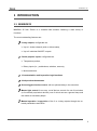
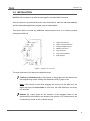
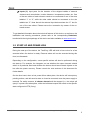
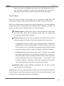
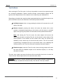
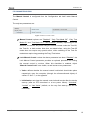
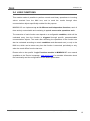
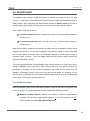
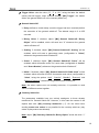
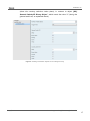
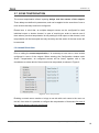
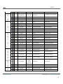
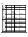
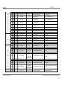
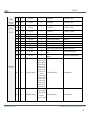
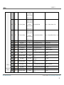
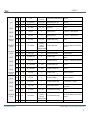
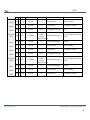
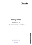
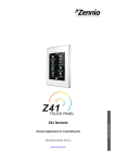
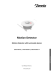
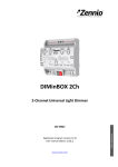
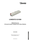
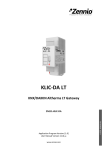
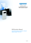
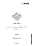
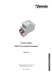
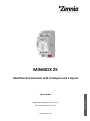
MINiBOX 25 Multifunction Actuator with 2 Outputs and 5 Inputs Application program version: [1.0] User manual edition: [1.0]_a www.zennio.com USER MANUAL ZN1IO-MN25 MINiBOX 25 CONTENTS Contents ........................................................................................................................................ 2 1 Introduction .......................................................................................................................... 3 1.1 MINiBOX25 and MINiBOX 45 ........................................................................................... 3 1.2 Installation........................................................................................................................ 4 1.3 Start-Up and Power Loss .................................................................................................. 5 2 Configuration......................................................................................................................... 6 2.1 General ............................................................................................................................. 6 2.2 Inputs ............................................................................................................................... 8 2.3 Outputs............................................................................................................................. 9 2.3.1 Manual Control ........................................................................................................ 9 2.4 Logic Functions ............................................................................................................... 13 2.5 Thermostats ................................................................................................................... 14 2.6 Master Light ................................................................................................................... 15 2.7 Scene Temporisation...................................................................................................... 18 ANNEX I. Communication Objects............................................................................................... 20 http://www.zennio.com Technical Support: http://zennioenglish.zendesk.com 2 MINiBOX 25 1 INTRODUCTION 1.1 MINIBOX25 MINiBOX 25 from Zennio is a versatile KNX actuator featuring a wide variety of functions. The most outstanding features are: 2 relay outputs, configurable as: Up to 1 shutter channel (with or without slats), Up to 2 individual ON/OFF outputs. 5 multi-purpose inputs, configurable as: Temperature probes, Binary inputs (i.e., pushbuttons, switches, sensors), Motion detectors. 10 customisable, multi-operation logic functions. 4 independent thermostats. Scene-triggered action control, with an optional delay in the execution. Master light control for an easy, out-of-the-box control of a set of luminaires (or functionally equivalent devices) one of which acts as a general lamp and the others as secondary lamps. Manual operation / supervision of the 2 or 4 relay outputs through the onboard pushbuttons and LEDs. http://www.zennio.com Technical Support: http://zennioenglish.zendesk.com 3 MINiBOX 25 1.2 INSTALLATION MINiBOX 25 connects to the KNX bus through the on-board KNX connector. Once the device is provided with power from the KNX bus, both the individual address and the associated application program may be downloaded. This device does not need any additional external power since it is entirely powered through the KNX bus. 1. Output LED Indicator. 2. Output Control Pushbutton. 3. Analogue-Digital Outputs. 4. KNX Bus Connector. 5. Prog./Test LED. 6. Prog./Test Pushbutton. 7. Relay Outputs. Figure 1. MINiBOX 25. Elements The main elements of the device are described next. Test/Prog. Pushbutton (6): a short press on this button sets the device into the programming mode, making the associated LED (5) light in red. Note: if this button is held while plugging the device into the KNX bus, the device will enter into safe mode. In such case, the LED will blink in red every 0.5 seconds. Outputs (7): output ports for the insertion of the stripped cables of the systems being controlled by the actuator (see section 2.3). Please secure the connection by means of the on-board screws. http://www.zennio.com Technical Support: http://zennioenglish.zendesk.com 4 MINiBOX 25 Inputs (3): input ports for the insertion of the stripped cables of external elements such as switches / motion detectors / temperature probes, etc. One of the two cables of each element needs to be connected to one of the slots labelled “1” to “6”, while the other cable should be connected to the slot labelled as “C”. Note that all the external input devices share the “C” slot for one of the two cables. Please secure the connection by means of the onboard screws. To get detailed information about the technical features of this device, as well as on the installation and security procedures, please refer to the corresponding Datasheet, bundled with the original package of the device and also available at www.zennio.com. 1.3 START-UP AND POWER LOSS During the start-up of the device, the Test/Prog. LED will blink in blue colour for a few seconds before the device is ready. External orders will not be executed during this time, but afterwards. Depending on the configuration, some specific actions will also be performed during the start-up. For example, the integrator can set whether the output channels should switch to a particular state and whether the device should send certain objects to the bus after the power recovery. Please consult the next sections of this document for further details. On the other hand, when a bus power failure takes place, the device will interrupt any pending actions, and will save its state so it can be recovered once the power supply is restored. For safety reasons, all shutter channels will be stopped (i.e., the relays will open) if a power loss takes place, while the individual outputs will switch to the specific state configured in ETS (if any). http://www.zennio.com Technical Support: http://zennioenglish.zendesk.com 5 MINiBOX 25 2 CONFIGURATION 2.1 GENERAL After importing the corresponding database in ETS and adding the device into the topology of the desired project, the configuration process begins by right-clicking into the device and selecting Edit parameters. ETS PARAMETERISATION The only parameterisable screen that is always available is General. From this screen it is possible to activate/deactivate all the required functionality. Figure 2. Default screen Once activated, Inputs, Outputs, Logical Functions, Thermostats, Master Light, Scene temporisation and Manual control bring additional tabs to the menu on the left. These functions and their parameters will be explained in later sections of this document. The Manual Control function is enabled by default, and so is the corresponding configuration tab. Sending of Indication Objects (0 and 1) on Bus Voltage Recovery: this parameter lets the integrator activate two new communication objects (“Reset 0” and “Reset 1”), which will be sent to the KNX bus with values “0” and “1” http://www.zennio.com Technical Support: http://zennioenglish.zendesk.com 6 MINiBOX 25 respectively whenever the device begins operation (for example, after a bus power failure). It is possible to parameterise a certain delay to this sending (0 to 255 seconds). Figure 3. Sending of Indication objects on bus voltage recovery http://www.zennio.com Technical Support: http://zennioenglish.zendesk.com 7 MINiBOX 25 2.2 INPUTS MINiBOX 25 incorporates 5 analogue/digital inputs, each configurable as a: Binary Input, for the connection of a pushbutton or a switch/sensor. Temperature Probe, to connect a temperature sensor (model ZN1ACNTC68 S/E/F from Zennio). Motion Detector, to connect a motion detector (models ZN1IO-DETEC-P and ZN1IO-DETEC-X from Zennio). For detailed information about the functionality and the configuration of the parameters involved, please refer to the following specific manuals, available under the MINiBOX 25 product section, at the Zennio homepage, www.zennio.com): “Binary Inputs in MINiBOX 25”, “Temperature Sensor in MINiBOX 25”, “Motion Detector in MINiBOX 25”. Notes: The ZN1IO-DETEC-P motion detector is compatible with a variety of Zennio devices. However, depending on the device it is actually being connected to, the functionality may differ slightly. Therefore, please refer specifically to the aforementioned manual “Zennio Motion Detector for MINiBOX 25”. Motion detectors with references ZN1IO-DETEC and ZN1IO-DETEC-N are not compatible with MINiBOX 25 (may report inaccurate measurements if connected to this device). When connected to MINiBOX 25, the rear micro-switch of model ZN1IODETEC-P should be set to position “Type B”. http://www.zennio.com Technical Support: http://zennioenglish.zendesk.com 8 MINiBOX 25 2.3 OUTPUTS The MINiBOX 25 actuator incorporates 2 relay outputs, each configurable as a: Individual binary outputs, which allows an independent control of loads. Shutter channels, which allow controlling the motion of shutters or blinds. For detailed information about the functionality and the configuration of the related parameters, please refer to the following specific manuals, all of them available at the Zennio homepage (www.zennio.com): Individual outputs in MINiBOX 25. Shutter channels in MINiBOX 25. 2.3.1 MANUAL CONTROL MINiBOX 25 allows manually switching the state of its output relays through the respective pushbuttons on the top of the device. A specific pushbutton is therefore available per output. Manual operation can be done in two different ways, named as Test On Mode (for testing purposes during the configuration of the device) and Test Off Mode (for a normal use, anytime). Whether both, only one, or none of these modes can be accessed needs to be parameterised in ETS. Moreover, it is possible to enable a specific binary object for locking and unlocking the manual control in runtime. Note: The Test Off mode will be active (unless it has been disabled by parameter) after a download or a reset with no need of a specific activation – the pushbuttons will respond to user presses from the start. On the contrary, switching to the Test On mode (unless disabled by parameter) needs to be done by long-pressing the Prog/Test button (for at least three seconds), until the LED is no longer red and turns yellow. From that moment, once the button is released, the LED light will remain green to confirm that the device has switched from the Test Off mode to the Test On http://www.zennio.com Technical Support: http://zennioenglish.zendesk.com 9 MINiBOX 25 mode. After that, an additional press will turn the LED yellow and then off, once the button is released. This way, the device leaves the Test On mode. Note that it will also leave this mode if a bus power failure takes place. Test Off Mode Under the Test Off Mode, the outputs can be controlled through both their communication objects and the actual pushbuttons located on the top of the device. When one of these buttons is pressed, the output will behave as if an order had been received through the corresponding communication object, depending on whether the output is configured as an individual output or as a shutter channel. Individual output: a simple press (short or long) will make the output switch its on-off state, which will be reported to the KNX bus through the corresponding status object, if enabled. Shutter Channel: when the button is pressed, the device will act over the output according to the length of the button press and to the current state. A long press makes the shutter start moving (upwards or downwards, depending on the button being pressed). The LED will light in green until the end of the motion. If the button gets pressed being the shutter already at the top or bottom positions, nothing will happen (the LED will not light). A short press will make the shutter drive stop (if in motion), as it normally does when a step/stop order is received from the KNX bus. In case of not being the shutter in motion, pressing the button does not cause any action, unless slats/lamellas have been parameterized – in such case, a step movement (up/down, depending on the button pressed) will take place. The status objects will be sent to the bus when corresponding. Disabled output: outputs disabled by parameter will not react to button presses under the Test Off mode. Regarding the lock, timer, alarm and scene functions, the device will behave under the Test Off mode as usual. Button presses during this mode are entirely analogous to the reception of the corresponding orders from the KNX bus. http://www.zennio.com Technical Support: http://zennioenglish.zendesk.com 10 MINiBOX 25 Test On Mode After entering the Test On mode, it will only be possible to control the outputs through the on-board pushbuttons. Orders received through communication objects will be ignored, with independence of the channel or the output they are addressed to. Depending on whether the output has been parameterised as an individual output or as part of a shutter channel, the reactions to the button presses will differ. Individual output: short or long pressing the button will commute the on-off state of the relay. Shutter channel: pressing the button will make the shutter drive move upward or downward (depending on the button) until the button is released again, thus ignoring the position of the shutter and the parameterised times. Note: after leaving the Test On mode, the status objects will recover the values they had prior to entering Test On. As the device is never aware of the actual position of the shutter (as the shutter drive does not provide any feedback), these values may not show the real position. This can be solved by performing a complete move-up or move-down order, or by calibrating the shutter position in the Test On mode until it matches the status objects. Disabled output: under the Test On mode, short and long presses will cause the same effect for disabled outputs as for individual outputs (i.e., the relay will switch its state). The lock, timer, alarm and scene functions will not work while the device is under the Test On mode. Status objects will not be sent to the bus, either. Important: the device is factory delivered with all the output channels configured as disabled outputs, and with both manual modes (Test Off and Test On) enabled. http://www.zennio.com Technical Support: http://zennioenglish.zendesk.com 11 MINiBOX 25 ETS PARAMETERISATION The Manual Control is configured from the Configuration tab itself under Manual Control. The only two parameters are: Figure 4. Manual control screen Manual Control: options are “Disabled”, “Only Test Mode Off”, “Only Test Mode On” and “Test Mode Off + Test On Mode” (default). Depending on the selection, the device will permit using the manual control under the Test Off, the Test On, or both modes. Note that, as stated before, using the Test Off mode does not require any special action, while switching to the Test On mode does require long-pressing the Prog./Test button. Lock Manual Control: unless the above parameter has been “Disabled”, the Lock Manual Control parameter provides an optional procedure for locking the manual control in runtime. When this checkbox is enabled, object “Manual Control Lock” turns visible, as well as two more parameters: Value: defines whether the manual control lock/unlock should take place respectively upon the reception (through the aforementioned object) of values “0” and “1”, or the opposite. Initialization: sets how the manual control should remain after the device start-up (after an ETS download or a bus power failure): “Unlocked”, “Locked” or “Last Value” (default; on the very first start-up, this will be Unlocked). http://www.zennio.com Technical Support: http://zennioenglish.zendesk.com 12 MINiBOX 25 2.4 LOGIC FUNCTIONS This module makes it possible to perform numeric and binary operations to incoming values received from the KNX bus, and to send the results through other communication objects specifically enabled for this purpose. MINiBOX 25 can implement up to 10 different and independent functions, each of them entirely customisable and consisting in up to 4 consecutive operations each. The execution of each function can depend on a configurable condition, which will be evaluated every time the function is triggered through specific, parameterisable communication objects. The result after executing the operations of the function can also be evaluated according to certain conditions and afterwards sent (or not) to the KNX bus, which can be done every time the function is executed, periodically or only when the result differs from the last one. Please refer to the specific “Logic Functions module in MINiBOX 25” user manual (available at the Zennio homepage, www.zennio.com) for detailed information about the functionality and the configuration of the related parameters. http://www.zennio.com Technical Support: http://zennioenglish.zendesk.com 13 MINiBOX 25 2.5 THERMOSTATS MINiBOX 25 implements four Zennio thermostats which can be enabled and configured independently. Please refer to the specific “Zennio Thermostat in MINiBOX 25” user manual (available at the Zennio homepage, www.zennio.com) for detailed information about the functionality and the configuration of the related parameters. http://www.zennio.com Technical Support: http://zennioenglish.zendesk.com 14 MINiBOX 25 2.6 MASTER LIGHT The Master Light function brings the option to monitor the state of up to 12 light sources –or any other functionally-similar element whose state is transmitted through a binary object– and, depending on those states, perform a master order every time a certain trigger signal (again, a binary value) is received through a specific object. Such master order will consist in: A general switch-off order, if at least one of the up to twelve status objects is found to be on. A courtesy switch-on order, if none of the up to twelve status objects is found to be on. Note that the above switch-off and switch-on orders are not necessarily a binary value being sent to the bus – it is up to the integrator the decision of what to send to the KNX bus in both cases: a shutter order, a thermostat setpoint or mode switch order, a constant value, a scene… Only the trigger object and the twelve status objects are required to be binary (on/off). The most typical scenario for this Master Light control would be a hotel room with a master pushbutton next to the door. When leaving the room, the guest will have the possibility of pressing on the master pushbutton and make all the lamps turn off together. Afterwards, back on the room and with all the lamps off, pressing on the same master pushbutton will only make a particular lamp turn on (e.g., the closest lamp to the door) – this is the courtesy switch-on. ETS PARAMETERISATION Once the Master Light function has been enabled, a specific tab will be included in the menu on the left. This new parameter screen contains the following options: Number of State Objects: defines the number of one-bit status objects required. The minimum (and default) value is “1”, and the maximum is “12”. These objects are called “[ML] Status Object n”. http://www.zennio.com Technical Support: http://zennioenglish.zendesk.com 15 MINiBOX 25 Trigger Value: sets the value (“0”, “1” or “0/1”, being the latter the default option) that will trigger, when received through “[ML] Trigger”, the master action (the general switch-off or the courtesy switch-on). General Switch-Off. Delay: defines a certain delay (once the trigger has been received) before the execution of the general switch-off. The allowed range is 0 to 255 seconds. Binary Value: if checked, object “[ML] General Switch-off: Binary Object” will be enabled, which will send one “0” whenever the general switch-off takes off. Scaling: if checked, object “[ML] General Switch-off: Scaling” will be enabled, which will send a percentage value (configurable in “Value”) whenever the general switch-off takes off. Scene: if checked, object “[ML] General Switch-off: Scene” will be enabled, which will send a scene run / save order (configurable in “Action” and “Scene Number”) whenever the general switch-off takes off HVAC: if checked, object “[ML] General Switch-off: HVAC mode” will be enabled, which will send an HVAC thermostat mode value (configurable in “Value”, being the options “Auto”, “Comfort”, “Standby”, “Economy” and “Building Protection”) whenever the general switch-off takes off Note: the above options are not mutually exclusive; it is possible to send values of different nature together. Courtesy Switch-On: The parameters available here are entirely analogous to those already mentioned for General Switch-Off. However, in this case the names of the objects start with “[ML] Courtesy Switch-On (…)”. On the other hand, sending scene save orders is not possible for the courtesy switch-on (only orders to play scenes are allowed). Note: object “[ML] Courtesy Switch-On: Binary Object” sends the value “1” http://www.zennio.com Technical Support: http://zennioenglish.zendesk.com 16 MINiBOX 25 (when the courtesy switch-on takes place), in contrast to object “[ML] General Switch-Off: Binary Object”, which sends the value “0” (during the general switch-off, as explained above). Figure 5. Sending of Indication objects on bus voltage recovery http://www.zennio.com Technical Support: http://zennioenglish.zendesk.com 17 MINiBOX 25 2.7 SCENE TEMPORISATION The scene temporisation allows imposing delays over the scenes of the outputs. These delays are defined in parameters, and can be applied to the execution of one or more scenes that may have been configured. Please bear in mind that, as multiple delayed scenes can be configured for each individual output or shutter channel, in case of receiving an order to execute one of them when a previous temporisation is still pending for that output or that channel, such temporisation will be interrupted and only the delay and the action of the new scene will be executed. ETS PARAMETERISATION Prior to setting the scene temporisation, it is necessary to have one or more scenes configured in some of the outputs. When entering the Configuration window under Scene Temporization, all configured scenes will be listed, together with a few checkboxes to select which of them need to be temporised, as shown in Figure 6. Figure 6. Scene temporisation Enabling a certain scene number n brings a new tab with such name to the menu on the left, from which it is possible to configure the temporisation of that scene for each of the outputs where it has been configured. http://www.zennio.com Technical Support: http://zennioenglish.zendesk.com 18 MINiBOX 25 Figure 7. Configuration of the scene temporisation Therefore, parameter “Scene m. Z Delay” defines the delay that will be applied to the action defined in Z for the execution of scene m (where Z may be a specific individual output, shutter channel or fan coil module). The range of this delay is 0 to 3600 seconds, 0 to 1440 minutes or 0 to 24 hours. http://www.zennio.com Technical Support: http://zennioenglish.zendesk.com 19 MINiBOX 25 ANNEX I. COMMUNICATION OBJECTS “Functional range” shows the values that, with independence of any other values permitted by the bus according to the object size, may be of any use or have a particular meaning because of the specifications or restrictions from both the KNX standard or the application program itself. Number 1 Size I/O Flags 1 Bit CT--- Data type (DPT) DPT_Trigger Functional Range 0/1 Reset 0 Name Function Voltage Recovery -> Sending of 0 CT--- DPT_Trigger 0/1 Reset 1 Voltage Recovery -> Sending of 1 1 Bit I C--W- DPT_Switch 0/1 Lock Manual Control 0 = Lock; 1 = Unlock 4 - 35 1 Bit 1 Bit I I C--WC--W- DPT_Switch DPT_Bool 0/1 0/1 Lock Manual Control [LF] (1 bit) Data Entry X 0 = Unlock; 1 = Lock Binary Data Entry (0/1) 36 - 51 1 Byte I C--W- DPT_Value_1_Ucount 0 - 255 [LF] (1 byte) Data Entry X 1 byte Data Entry (0-255) DPT_Value_2_Ucount 0 - 65535 DPT_Value_2_Count -32768 - 32767 [LF] (2 bytes) Data Entry X 2 bytes Data Entry DPT_Value_Temp -273,00 - 670760,00 DPT_Value_4_Count -2147483648 2147483647 [LF] (4 bytes) Data Entry X 4 bytes Data Entry 2 3 52 - 67 1 Bit 2 Byte I C--W- 68 - 75 4 Byte I C--W- 1 Bit O CTR-- DPT_Bool 0/1 [LF] Function X - Result (1 bit) Boolean 76, 77, 78, 79, 80, 81, 82, 83, 84, 85 1 Byte 2 Byte O O CTR-CTR-- DPT_Value_1_Ucount DPT_Value_2_Ucount [LF] Function X - Result [LF] Function X - Result (1 byte) Unsigned (2 bytes) Unsigned 4 Byte O CTR-- DPT_Value_4_Count 0 - 255 0 - 65535 -2147483648 2147483647 [LF] Function X - Result (4 bytes) Signed 86 1 Byte I C--W- DPT_SceneControl 0-63; 128-191 1 Bit I C--W- DPT_BinaryValue 0/1 [OX] On/Off 0 – 63 (Execute 1 – 64); 128 – 191 (Save 1 – 64) N.O. (0=Open Relay; 1=Close Relay) 1 Bit I C--W- DPT_BinaryValue 0/1 [OX] On/Off N.C. (0=Close Relay; 1= Open Relay) 88, 96 89, 97 1 Bit 1 Bit O I CTR-C--W- DPT_BinaryValue DPT_Enable 0/1 0/1 [OX] On/Off (Status) [OX] Lock 0=Output Off; 1=Output On 0=Unlock; 1=Lock 90, 98 1 Bit I C--W- DPT_Start 0/1 [OX] Timer 0=Switch Off; 1=Switch On 91, 99 1 Bit I C--W- DPT_Start 0/1 [OX] Flashing 0=Stop; 1=Start 92, 100 1 Bit 1 Bit I I C--WC--W- DPT_Alarm DPT_Alarm 0/1 0/1 [OX] Alarm [OX] Alarm 0=Normal; 1=Alarm 0=Alarm; 1=Normal 93, 101 1 Bit I C--W- DPT_Trigger 0/1 [OX] Unfreeze Alarm Alarm=0 + Unfreeze=1 => End Alarm 87, 95 http://www.zennio.com [Outputs] Scenes Technical Support: http://zennioenglish.zendesk.com 20 MINiBOX 25 94, 102 1 Bit O CTR-- DPT_Trigger 0/1 103 1 Byte I C--W- DPT_SceneControl 0-63; 128-191 104 1 Bit 1 Bit I I C--WC--W- DPT_UpDown DPT_Step 1 Bit I C--W- 1 Bit 1 Bit I O C--WCTR-- 108 1 Bit O CTR-- 109 1 Byte O CTR-- 110 111 1 Byte 1 Byte O I CTR-C--W- 112 1 Byte I 113 1 Bit 1 Bit I I 1 Bit 1 Bit 115 116 [OX] Warning Time (Status) 0=Normal; 1=Warning [Shutter] Scenes 0 - 63 (Execute 1 - 64); 128 - 191 (Save 1 64) 0/1 0/1 [CX] Move [CX] Stop/Step 0=Raise; 1=Lower 0=Stop/StepUp; 1=Stop/StepDown DPT_Trigger 0/1 [CX] Stop 0=Stop; 1=Stop DPT_Enable DPT_Switch 0/1 0/1 [CX] Lock [CX] Rising Relay (Status) 0=Unlock; 1=Lock 0=Opened; 1=Closed DPT_Switch 0/1 [CX] Lowering Relay (Status) 0=Opened; 1=Closed DPT_Scaling 0% - 100% [CX] Shutter Position (Status) 0%=Top; 100%=Bottom DPT_Scaling DPT_Scaling 0% - 100% 0% - 100% [CX] Slats Position (Status) [CX] Shutter Positioning 0%=Open; 100%=Closed 0%=Top; 100%=Bottom C--W- DPT_Scaling 0% - 100% [CX] Slats Positioning 0%=Open; 100%=Closed C--WC--W- DPT_Alarm DPT_Alarm 0/1 0/1 [CX] Alarm [CX] Alarm 0=No Alarm; 1=Alarm 0=Alarm; 1=No Alarm I C--W- DPT_Alarm 0/1 [CX] Alarm 2 0=No Alarm; 1=Alarm I C--W- DPT_Alarm 0/1 [CX] Alarm 2 0=Alarm; 1=No Alarm 1 Bit 1 Bit I I C--WC--W- DPT_Trigger DPT_Scene_AB 0/1 0/1 [CX] Unfreeze Alarm [CX] Move (Reversed) Alarm=0 + Unfreeze=1 => End Alarm 0=Lower; 1=Raise 117 1 Bit I C--W- DPT_Trigger 0/1 [CX] Direct Positioning 0=No Action; 1=Go to Position 118 119 1 Bit 1 Bit I I C--WC--W- DPT_Trigger DPT_Trigger 0/1 0/1 [CX] Direct Positioning 2 [CX] Direct Positioning (Save) 0=No Action; 1=Go to Position 0=No Action; 1=Save Current Position 120 1 Bit I C--W- DPT_Trigger 0/1 [CX] Direct Positioning 2 (Save) 0=No Action; 1=Save Current Position 121 122, 152, 182, 212 1 Byte I C--W- DPT_SceneControl 0-63; 128-191 [Thermostat] Scene Input Scene Value 2 Byte I C--W- DPT_Value_Temp -273.00 - 670760.00 [TX] Temperature Source 1 External Sensor Temperature 123, 153, 183, 213 2 Byte I C--W- DPT_Value_Temp -273.00 - 670760.00 [TX] Temperature Source 2 External Sensor Temperature 124, 154, 184, 214 2 Byte O CTR-- DPT_Value_Temp -273.00 - 670760.00 [TX] Effective Temperature Effective Control Temperature 125, 155, 185, 215 1 Byte I C--W- DPT_HVACMode 1=Comfort 2=Standby [TX] Special Mode 3=Economy 4=Building Protection 1-byte HVAC Mode 1 Bit I C--W- DPT_Trigger 0/1 [TX] Special Mode: comfort 0 = Nothing; 1 = Trigger 1 Bit 1 Bit I I C--WC--W- DPT_Switch DPT_Trigger 0/1 0/1 [TX] Special Mode: comfort [TX] Special Mode: standby 0 = Off; 1 = On 0 = Nothing; 1 = Trigger 1 Bit I C--W- DPT_Switch 0/1 [TX] Special Mode: standby 0 = Off; 1 = On 105 106 107 114 126, 156, 186, 216 127, 157, 187, 217 http://www.zennio.com Technical Support: http://zennioenglish.zendesk.com 21 MINiBOX 25 128, 158, 188, 218 1 Bit I C--W- DPT_Trigger 0/1 [TX] Special Mode: economy 0 = Nothing; 1 = Trigger 1 Bit I C--W- DPT_Switch 0/1 [TX] Special Mode: economy 0 = Off; 1 = On 129, 159, 189, 219 1 Bit 1 Bit I I C--WC--W- DPT_Trigger DPT_Switch 0/1 0/1 [TX] Special Mode: protection [TX] Special Mode: protection 0 = Nothing; 1 = Trigger 0 = Off; 1 = On 130, 160, 190, 220 1 Bit I C--W- DPT_Window_Door 0/1 [TX] Window Status (input) 0 = Closed; 1 = Open 131, 161, 191, 221 1 Bit I C--W- DPT_Trigger 0/1 [TX] Comfort Prolongation 0 = Nothing; 1 = Timed Comfort 132, 162, 192, 222 1 Byte O CTR-- DPT_HVACMode 2 Byte I C--W- 2 Byte I C--W- 134, 164, 194, 224 1 Bit I C--W- DPT_Step 0/1 135, 165, 195, 225 2 Byte I C--W- DPT_Value_Tempd -670760.00 670760.00 2 Byte O CTR-- DPT_Value_Temp -273.00 - 670760.00 [TX] Setpoint Status Current Setpoint 2 Byte O CTR-- DPT_Value_Temp -273.00 - 670760.00 [TX] Basic Setpoint Status Current Basic Setpoint 138, 168, 198, 228 2 Byte O CTR-- DPT_Value_Tempd -670760.00 670760.00 139, 169, 199, 229 1 Bit 1 Bit I I C--WC--W- DPT_Reset DPT_Reset 140, 170, 200, 230 1 Bit I C--W- 1 Bit O 1 Bit 133, 163, 193, 223 136, 166, 196, 226 137, 167, 197, 227 141, 171, 201, 231 142, 172, 202, 232 143, 173, 203, 233 144, 174, 204, 234 145, 175, 205, 235 146, 176, 206, 236 http://www.zennio.com 1=Comfort 2=Standby [TX] Special Mode Status 3=Economy 4=Building Protection 1-byte HVAC Mode DPT_Value_Temp -273.00 - 670760.00 [TX] Setpoint Thermostat Setpoint Input DPT_Value_Temp -273.00 - 670760.00 [TX] Basic Setpoint Reference Setpoint [TX] Setpoint Step 0 = -0.5ºC; 1 = +0.5ºC [TX] Setpoint Offset Float Offset Value [TX] Setpoint Offset Status Current Setpoint Offset 0/1 0/1 [TX] Setpoint Reset [TX] Offset Reset Reset Setpoint to Default Reset offset DPT_Heat_Cool 0/1 [TX] Mode 0 = Cool; 1 = Heat CTR-- DPT_Heat_Cool 0/1 [TX] Mode Status 0 = Cool; 1 = Heat I C--W- DPT_Switch 0/1 [TX] On/Off 0 = Off; 1 = On 1 Bit O CTR-- DPT_Switch 0/1 [TX] On/Off Status 0 = Off; 1 = On 1 Byte O CTR-- DPT_Scaling 0% - 100% [TX] Control Variable (Cool) PI Control (Continuous) 1 Byte O CTR-- DPT_Scaling 0% - 100% [TX] Control Variable (Heat) PI Control (Continuous) 1 Bit O CTR-- DPT_Switch 0/1 [TX] Control Variable (Cool) 2-Point Control 1 Bit O CTR-- DPT_Switch 0/1 [TX] Control Variable (Cool) PI Control (PWM) Technical Support: http://zennioenglish.zendesk.com 22 MINiBOX 25 147, 177, 207, 237 148, 178, 208, 238 149, 179, 209, 239 150, 180, 210, 240 151, 181, 201, 241 242 1 Bit O CTR-- DPT_Switch 0/1 [TX] Control Variable (Heat) 2-Point Control 1 Bit O CTR-- DPT_Switch 0/1 [TX] Control Variable (Heat) PI Control (PWM) 1 Bit O CTR-- DPT_Switch 0/1 [TX] Additional Cool Temp >= (Setpoint+Band) => "1" 1 Bit O CTR-- DPT_Switch 0/1 [TX] Additional Heat Temp <= (Setpoint-Band) => "1" 1 Bit O CTR-- DPT_Switch 0/1 [TX] PI State (Cool) 0 = PI signal 0%; 1 = PI signal greater than 0% 1 Bit O CTR-- DPT_Switch 0/1 [TX] PI State (Heat) 1 Bit I C--W- DPT_Trigger 0/1 [ML] Trigger 0 = PI signal 0%; 1 = PI signal greater than 0% Trigger the Master Light Function 243 1 Bit I C--W- DPT_Switch 0/1 [ML] Status Object 1 Binary Status 244 245 1 Bit 1 Bit I I C--WC--W- DPT_Switch DPT_Switch 0/1 0/1 [ML] Status Object 2 [ML] Status Object 3 Binary Status Binary Status 246 1 Bit I C--W- DPT_Switch 0/1 [ML] Status Object 4 Binary Status 247 1 Bit I C--W- DPT_Switch 0/1 [ML] Status Object 5 Binary Status 248 249 1 Bit 1 Bit I I C--WC--W- DPT_Switch DPT_Switch 0/1 0/1 [ML] Status Object 6 [ML] Status Object 7 Binary Status Binary Status 250 1 Bit I C--W- DPT_Switch 0/1 [ML] Status Object 8 Binary Status 251 252 1 Bit 1 Bit I I C--WC--W- DPT_Switch DPT_Switch 0/1 0/1 [ML] Status Object 9 [ML] Status Object 10 Binary Status Binary Status 253 1 Bit I C--W- DPT_Switch 0/1 [ML] Status Object 11 Binary Status 254 1 Bit I C--W- DPT_Switch 0/1 [ML] Status Object 12 Binary Status 255 256 1 Bit 1 Byte CT--CT--- DPT_Switch DPT_Scaling 0/1 0% - 100% [ML] General Switch-Off: Binary Object [ML] General Switch-Off: Scaling Off Sending 0-100% 257 1 Byte CT--- DPT_SceneControl 0-63; 128-191 [ML] General Switch-Off: Scene Scene Sending 1 Byte CT--- 259 1 Bit CT--- DPT_Switch 260 1 Byte CT--- DPT_Scaling 261 1 Byte CT--- DPT_SceneControl 262 1 Byte CT--- DPT_HVACMode 263, 267, 271, 275, 279 2 Byte CTR-- DPT_Value_Temp 258 http://www.zennio.com O DPT_HVACMode 1=Comfort 2=Standby [ML] General Switch-Off: HVAC mode 3=Economy 4=Building Protection 0/1 [ML] Courtesy Switch-On: Binary Object 0% - 100% [ML] Courtesy Switch-On: Scaling Auto, Comfort, Standby, Economy, Building Protection On Sending 0-100% 0-63; 128-191 [ML] Courtesy Switch-On: Scene 1=Comfort 2=Standby [ML] Courtesy Switch-On: HVAC mode 3=Economy 4=Building Protection Scene Sending -273.00 - 670760.00 [IX] Current Temperature Temperature sensor value Auto, Comfort, Standby, Economy, Building Protection Technical Support: http://zennioenglish.zendesk.com 23 MINiBOX 25 264, 268, 272, 276, 280 1 Bit O CTR-- DPT_Alarm 0/1 [IX] Overcooling 0 = No Alarm;1 = Alarm 265, 269, 273, 277, 281 1 Bit O CTR-- DPT_Alarm 0/1 [IX] Overheating 0 = No Alarm;1 = Alarm 1 Bit O CTR-- DPT_Alarm 0/1 [IX] Probe Error 0 = No Alarm;1 = Alarm 1 Bit I C--W- DPT_Switch 0/1 [IX] Input Lock 1 = Locked; 0 = Unlocked 1 Bit CT--- DPT_Switch 0/1 [IX] [Short Press] 0 Sending of 0 1 Bit 1 Bit CT--CT-W- DPT_Switch DPT_Switch 0/1 0/1 [IX] [Short Press] 1 [IX] [Short Press] 0/1 Switching Sending of 1 Switching 0/1 1 Bit CT--- DPT_UpDown 0/1 [IX] [Short Press] Move Up Shutter Sending of 0 (Up) 1 Bit 1 Bit CT--CT--- DPT_UpDown DPT_UpDown 0/1 0/1 [IX] [Short Press] Move Down Shutter Sending of 1 (Down) [IX] [Short Press] Move Up/Down Shutter Switching 0/1 (Up/Down) 1 Bit CT--- DPT_Step 0/1 [IX] [Short Press] Stop/Step Up Shutter Sending of 0 (Stop/Step up) 0/1 [IX] [Short Press] Stop/Step Down Shutter Sending of 1 (Stop/Step down) 0/1 [IX] [Short Press] Stop/Step Shutter (switched) Switching of 0/1 (Stop/Step up/down) 266, 270, 274, 278, 282 283, 289, 295, 301, 307 1 Bit 1 Bit I CT--CT--- DPT_Step DPT_Step 284, 290, 296, 302, 308 http://www.zennio.com 4 Bit CT--- DPT_Control_Dimming 4 Bit CT--- DPT_Control_Dimming 0x0 (Stop) 0x1 (Dec. by 100%) 0x2 (Dec. by 50%) 0x3 (Dec. by 25%) 0x4 (Dec. by 12%) 0x5 (Dec. by 6%) 0x6 (Dec. by 3%) 0x7 (Dec. by 1%) [IX] [Short Press] Brighter 0x8 (Stop) 0x9 (Inc. by 100%) 0xA (Inc. by 50%) 0xB (Inc. by 25%) 0xC (Inc. by 12%) 0xD (Inc. by 6%) 0xE (Inc. by 3%) 0xF (Inc. by 1%) 0x0 (Stop) 0x1 (Dec. by 100%) 0x2 (Dec. by 50%) … [IX] [Short Press] Darker 0x8 (Stop) 0x9 (Inc. by 100%) … Increase Brightness Decrease Brightness Technical Support: http://zennioenglish.zendesk.com 24 MINiBOX 25 0xF (Inc. by 1%) 4 Bit CT--- DPT_Control_Dimming 1 Bit CT--- DPT_Switch 1 Bit CT--- DPT_Switch 0/1 CT-WCT--- DPT_Switch DPT_SceneControl CT--- 1 Bit 1 Byte I 1 Byte 1 Bit 285, 291, 297, 303, 309 I/O C T R W - Sending of 1 (ON) Sending of 0 (OFF) 0/1 0-63; 128-191 [IX] [Short Press] Dimmer ON/OFF [IX] [Short Press] Run Scene Switching 0/1 Sending of 0 - 63 DPT_SceneControl 0-63; 128-191 [IX] [Short Press] Save Scene Sending of 128 - 191 DPT_Switch 0/1 [IX] [Switch/Sensor] Edge Sending of 0 or 1 CT--- DPT_Value_1_Ucount 0 - 255 1 Byte CT--- DPT_Scaling 0% - 100% 2 Byte CT--- DPT_Value_2_Ucount 0 - 65535 2 Byte CT--- 9.xxx 1 Byte I C--W- DPT_Scaling -671088.64 670760.96 0% - 100% 1 Byte I C--W- DPT_Scaling 0% - 100% CT--CT--- DPT_Switch DPT_Switch [IX] [Short Press] Constant Value (Integer) [IX] [Short Press] Constant Value (Percentage) [IX] [Short Press] Constant Value (Integer) 0 - 255 0% - 100% 0 - 65535 [IX] [Short Press] Constant Value (float) Float value [IX] [Short Press] Shutter Status (input) 0% = Top; 100% = Bottom [IX] [Short Press] Dimming Status (input) 0% - 100% 0/1 0/1 [IX] [Long Press] 0 [IX] [Long Press] 1 Sending of 0 Sending of 1 CT-W- DPT_Switch 0/1 [IX] [Long Press] 0/1 Switching Switching 0/1 1 Bit 1 Bit CT--CT--- DPT_UpDown DPT_UpDown 0/1 0/1 [IX] [Long Press] Move Up Shutter [IX] [Long Press] Move Down Shutter Sending of 0 (Up) Sending of 1 (Down) 1 Bit CT--- DPT_UpDown 0/1 [IX] [Long Press] Move Up/Down Shutter Switching 0/1 (Up/Down) 1 Bit CT--- DPT_Step 0/1 [IX] [Long Press] Stop/Step Up Shutter 1 Bit http://www.zennio.com Switch Bright/Dark [IX] [Short Press] Dimmer OFF 1 Byte 1 Bit 1 Bit 286, 292, 298, 304, 310 0x0 (Stop) 0x1 (Dec. by 100%) 0x2 (Dec. by 50%) … [IX] [Short Press] Brighter/Darker 0x8 (Stop) 0x9 (Inc. by 100%) … 0xF (Inc. by 1%) 0/1 [IX] [Short Press] Dimmer ON I 1 Bit CT--- DPT_Step 0/1 1 Bit CT--- DPT_Step 0/1 4 Bit CT--- DPT_Control_Dimming [IX] [Long Press] Stop/Step Down Shutter [IX] [Long Press] Stop/Step Shutter (switched) 0x0 (Stop) 0x1 (Dec. by 100%) [IX] [Long Press] Brighter 0x2 (Dec. by 50%) Sending of 0 (Stop/Step up) Sending of 1 (Stop/Step down) Switching of 0/1 (Stop/Step up/down) Long Pr. -> Brighter; Release -> Stop Technical Support: http://zennioenglish.zendesk.com 25 MINiBOX 25 … 0x8 (Stop) 0x9 (Inc. by 100%) … 0xF (Inc. by 1%) CT--- 4 Bit Long Pr. -> Brighter/Darker; Release -> Stop DPT_Control_Dimming 1 Bit 1 Bit CT--CT--- DPT_Switch DPT_Switch 0/1 0/1 [IX] [Long Press] Dimmer ON [IX] [Long Press] Dimmer OFF Sending of 1 (ON) Sending of 0 (OFF) [IX] [Long Press] Dimmer ON/OFF Switching 0/1 [IX] [Long Press] Run Scene [IX] [Long Press] Save Scene Sending of 0 - 63 Sending of 128 - 191 CT-W- DPT_Switch 0/1 CT--CT--- DPT_SceneControl DPT_SceneControl 0-63; 128-191 0-63; 128-191 CTR-- DPT_Alarm 0/1 [IX] [Switch/Sensor] Alarm: Breakdown or sabotage 1 = Alarm; 0 = No Alarm 2 Byte CT--- 9.xxx -671088.64 670760.96 [IX] [Long Press] Constant Value (float) Float value 2 Byte CT--- DPT_Value_2_Ucount 0 - 65535 [IX] [Long Press] Constant Value (Integer) 0 - 65535 1 Byte CT--- DPT_Scaling 0% - 100% [IX] [Long Press] Constant Value (Percentage) 0% - 100% 1 Byte CT--- DPT_Value_1_Ucount 0 - 255 [IX] [Long Press] Constant Value (Integer) 0 - 255 1 Bit CT--- DPT_Trigger 0/1 [IX] [Long Press/Release] Stop Shutter Release -> Stop Shutter 1 Bit http://www.zennio.com 0x0 (Stop) 0x1 (Dec. by 100%) 0x2 (Dec. by 50%) … [IX] [Long Press] Brighter/Darker 0x8 (Stop) 0x9 (Inc. by 100%) … 0xF (Inc. by 1%) CT--- 1 Bit 288, 294, 300, 306, 312 Long Pr. -> Darker; Release -> Stop 4 Bit I 1 Byte 1 Byte 287, 293, 299, 305, 311 DPT_Control_Dimming 0x0 (Stop) 0x1 (Dec. by 100%) 0x2 (Dec. by 50%) … [IX] [Long Press] Darker 0x8 (Stop) 0x9 (Inc. by 100%) … 0xF (Inc. by 1%) O 1 Byte I C--W- DPT_Scaling 0% - 100% [IX] [Long Press] Dimming Status (input) 0% - 100% 1 Byte I C--W- DPT_Scaling 0% - 100% [IX] [Long Press] Shutter Status (input) 0% = Top; 100% = Bottom [I5] [Short Press] Constant Value (Integer) 0 - 65535 2 Byte CT--- DPT_Value_2_Ucount 0 - 65535 Technical Support: http://zennioenglish.zendesk.com 26 MINiBOX 25 2 Byte 313 1 Byte 314 315, 344, 373, 402, 431 1 Byte 316, 345, 374, 403, 432 317, 346, 375, 404, 433 318, 347, 376, 405, 434 I CT--- 9.xxx -671088.64 670760.96 C--W- DPT_SceneControl CT--- DPT_SceneControl [I5] [Short Press] Constant Value (float) Float value 0-63; 128-191 [Motion Detector] Scene Input Scene Value 0-63; 128-191 [Motion Detector] Scene Output Scene Value [IX] Luminosity 0-100% 1 Byte O CTR-- DPT_Scaling 0% - 100% 1 Bit O CTR-- DPT_Alarm 0/1 [IX] Open Circuit Error 0 = No Error; 1 = Open Circuit Error 1 Bit O CTR-- DPT_Alarm 0/1 [IX] Short Circuit Error 0 = No Error; 1 = Short Circuit Error 1 Byte O CTR-- DPT_Scaling 0% - 100% [IX] Presence State (Scaling) 0-100% 1=Comfort 2=Standby [IX] Presence State (HVAC) 3=Economy 4=Building Protection 319, 348, 377, 406, 435 1 Byte O CTR-- DPT_HVACMode 320, 349, 378, 407, 436 1 Bit 1 Bit O O CTR-CTR-- DPT_Occupancy DPT_Trigger 0/1 0/1 [IX] Presence State (Binary) [IX] Presence: Slave Output Binary Value 1 = Motion Detected 321, 350, 379, 408, 437 1 Bit I C--W- DPT_Window_Door 0/1 [IX] Presence Trigger Binary Value to Trigger the Presence Detection 1 Bit I C--W- DPT_Trigger 0/1 [IX] Presence: Slave Input 0 = Nothing; 1 = Detection from slave device 2 Byte I C--W- DPT_TimePeriodSec 0 - 65535 [IX] Presence: Waiting Time 0-65535 s. 2 Byte I C--W- DPT_TimePeriodSec 0 - 65535 [IX] Presence: Listening Time 1-65535 s. 1 Bit I C--W- DPT_Switch 0/1 [IX] Presence: Enable According to parameters 1 Bit I C--W- DPT_Switch 0/1 [IX] Presence: Day/Night According to parameters 1 Bit O CTR-- DPT_Occupancy 0/1 [IX] Presence: Occupancy State 0 = Not Occupied; 1 = Occupied 1 Bit I C--W- DPT_Trigger 0/1 [IX] External Motion Detection 0 = Nothing; 1 = Motion detected by an external sensor 1 Byte O CTR-- DPT_Scaling 0% - 100% [IX] [C1] Detection State (Scaling) 0-100% 330, 359, 388, 417, 446 1 Byte O CTR-- DPT_HVACMode 331, 360, 389, 1 Bit O CTR-- DPT_Switch 322, 351, 380, 409, 438 323, 352, 381, 410, 439 324, 353, 382, 411, 440 325, 354, 383, 412, 441 326, 355, 384, 413, 442 327, 356, 385, 414, 443 328, 357, 386, 415, 444 329, 358, 387, 416, 445 http://www.zennio.com Auto, Comfort, Standby, Economy, Building Protection 1=Comfort 2=Standby [IX] [C1] Detection State (HVAC) 3=Economy 4=Building Protection 0/1 [IX] [C1] Detection State (Binary) Auto, Comfort, Standby, Economy, Building Protection Binary Value Technical Support: http://zennioenglish.zendesk.com 27 MINiBOX 25 418, 447 332, 361, 390, 419, 448 333, 362, 391, 420, 449 334, 363, 392, 421, 450 1 Bit I C--W- DPT_Switch 0/1 [IX] [C1] Enable Channel According to parameters 1 Bit I C--W- DPT_Switch 0/1 [IX] [C1] Force State 0 = No Detection; 1 = Detection 1 Byte O CTR-- DPT_Scaling 0% - 100% [IX] [C2] Detection State (Scaling) 0-100% 1=Comfort 2=Standby [IX] [C2] Detection State (HVAC) 3=Economy 4=Building Protection 335, 364, 393, 422, 451 1 Byte O CTR-- DPT_HVACMode 335, 364, 393, 422, 452 1 Bit O CTR-- DPT_Switch 0/1 [IX] [C2] Detection State (Binary) Binary Value 337, 366, 395, 424, 453 1 Bit I C--W- DPT_Switch 0/1 [IX] [C2] Enable Channel According to parameters 338, 367, 396, 425, 454 1 Bit I C--W- DPT_Switch 0/1 [IX] [C2] Force State 0 = No Detection; 1 = Detection 339, 368, 397, 426, 455 1 Byte O CTR-- DPT_Scaling 0% - 100% [IX] [C3] Detection State (Scaling) 0-100% 340, 369, 398, 427, 456 341, 370, 399, 428, 457 342, 371, 400, 429, 458 343, 372, 401, 430, 459 http://www.zennio.com 1=Comfort 2=Standby [IX] [C3] Detection State (HVAC) 3=Economy 4=Building Protection Auto, Comfort, Standby, Economy, Building Protection Auto, Comfort, Standby, Economy, Building Protection 1 Byte O CTR-- DPT_HVACMode 1 Bit O CTR-- DPT_Switch 0/1 [IX] [C3] Detection State (Binary) Binary Value 1 Bit I C--W- DPT_Switch 0/1 [IX] [C3] Enable Channel According to parameters 1 Bit I C--W- DPT_Switch 0/1 [IX] [C3] Force State 0 = No Detection; 1 = Detection Technical Support: http://zennioenglish.zendesk.com 28 Join and send us your inquiries about Zennio devices: http://zennioenglish.zendesk.com Zennio Avance y Tecnología S.L. C/ Río Jarama, 132. Nave P-8.11 45007 Toledo (Spain). Tel. +34 925 232 002. Fax. +34 925 337 310. www.zennio.com [email protected]