1
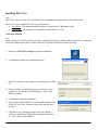
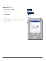
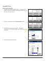
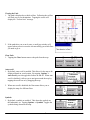
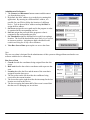
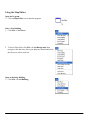
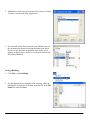
EECS NAV
User Manual
EECS Navigational
System
Table of Contents
Installing EECS Nav
2
Running EECS Nav
4
Using EECS Nav
5
Using the Map Editor
9
1
Installing EECS Nav
Note
EECS Nav requires a Pocket PC with Ekahau Client installed and a supported 802.11b wireless card.
There are 2 ways to install EECS Nav on your Pocket PC.
• ActiveSync : This method installs the software using a host PC and transfer cable.
• Over-the-air : This method is for installation without the use of a PC.
ActiveSync Method
Note:
Before starting, be sure Microsoft ActiveSync is installed on the host computer and the Pocket PC is connected.
Consult the manuals that came with the Pocket PC for further information on how to do this.
1. Double click EECS Nav Setup to begin the installation.
2. Click Next to continue the installation process.
3. Select the location for the software to be installed on the host
PC.
4. Choose whether to install this program for all users of the
computer or just the one currently logged in. Then, click
Next to continue.
5. Click Next to begin the installation.
6. If you wish to install EECS Nav to the default location on the
Pocket PC, click Yes. Otherwise choose No and select the
location.
7. Click Yes to any remaining prompts and verify that the
software is installed on both the host computer and Pocket
PC. EECS Nav is now installed.
2
Over-the-air Method
1. On the Pocket PC, run Internet Explorer and navigate to the
website hosting the EECS Nav setup file
2. Tap the file name to begin the download. Be sure Open file
after download is checked. Tap Yes.
3. Tap Next
4. Read the Read Me file displayed onscreen and tap Next
5. Read the licensing agreement. Tap I agree if you agree to the
terms. Tap Next.
6. Tap Next to install to the default location.
7. Tab Finish to complete the installation.
3
Running EECS Nav
1. On the Pocket PC, tap Start.
2. Tap Programs
3. Tap EECS Nav
4. EECS Nav will start, displaying your current location with a
Maize and Blue icon with the words “You Are Here”
displayed next to it.
4
Using EECS Nav
Find a specific destination
1. By default, the destination panel is shown. The panel can be
toggled on and off via tapping in the bottom left hand corner. If
the panel is off, tap to show it.
2. To select a destination, tap the New Destination button.
3. The New Destination form will appear. The specific
destinations are categorized by floor. Select the floor you wish
to travel to.
4. Select the destination on this floor
5
5. Tapping Find will return you to the main screen with the path
being drawn from your current location to your destination.
Find a nearest destination
1. If the panel is not shown see step one above.
2. To select a nearest location, tap the New Destination button.
3. Select the location you wish to find.
4. Tapping Find will return you to the main screen with the path
being drawn from your current location to the nearest location
of that destination type.
6
Viewing the Path
1. The path is displayed as a thick red line. Following the red line
will lead you to your destination. Tapping the screen will
display the “You are here” message.
2. If the path takes you to an elevator, a small pop window will
appear when you arrive near the elevator telling you which floor
you need to go to.
Clear Path
1. Tapping the Clear button removes the path from the map.
Auto scroll
1. By default, auto scroll is enabled. This allows for the map to be
displayed based on your location. By tapping, Options ⇒
Auto Scroll, you can toggle this feature on and off. When auto
scroll is disabled, it allows you to navigate around the map by
tapping the scroll bars or by dragging the map.
2. When auto scroll is disabled, the floor menu allows you to
display the map of a different floor.
Symbols
1. By default, symbols are enabled. This draws the symbols on
the bathrooms, etc. Tapping Options ⇒ Symbols. Toggles the
symbols being drawn on the map.
7
Administrator Preferences
1. The Connect and Disconnect button connect and disconnect
you from the data server.
2. By default, the MAC address is set to the device running this
application. By entering in a different MAC address, it is
possible for your PDA to follow the location of a different
device. Type in the new MAC address and tap Set MAC to
assign the new address.
3. Set Server assigns the server path used in the program to what
is contained in the corresponding text box.
4. Set Port assigns the port used in the program to what is
contained in the corresponding text box.
5. Set Threshold assigns the threshold to be used for accepting a
location. The lower the threshold the more likely it is to receive
an incorrect position. Assigning too high a threshold could
result in receiving few if any correct locations.
6. View Raw Server Data opens up the raw server data form.
Note:
The raw server data is designed for the administrators of this system to debug problems unrelated to our
software with the device connecting.
Raw Server Data
1. Coords describe the coordinates being assigned from the data
server.
2. RelCoord describe the relative coordinates with respect to that
zone.
3. Location describes the floor and the name of the zone that is
assigned from the data server.
4. The lowest box on the left describes the confidence being
received for the current location.
5. The lowest box on the right describes the timestamp for the last
location received for this device
6. The box occupying the bottom half of the screen is actual data
that the server is dumping out, in real time.
8
Using the Map Editor
Open the Program
1. Click on Map Editor icon to start the program
Start a New Building
1. Click File ⇒ New Floor
2. To load a Floor Plan, click File ⇒ Load Background, then
navigate to the directory where your plans are located and select
the floor you wish to work on.
Open an Existing Building
1. Click File ⇒ Load Building
9
2. Locate your Building File using the file browser
Nodes
1. Click anywhere on the map to create a node.
2. Use the fields on the right hand side of the window to change
the properties of the selected node, indicated by a blue box on
the map. Be sure that the Node names for Floor Above and
Below are valid node names.
3. Click on the RoomList field, then the
button to bring up
the Room List entry box, where rooms that are associated with
each node are entered, one per line. Feel free to add a specific
room to as many nodes as you wish, as the PDA application
will automatically strip out any duplicates.
4. To Remove a Node, right click on the desired node and click
Delete. All edges attached to that node will also be removed.
10
Edges
1. To Add an Edge between nodes by right clicking on one node,
selecting Draw Line from the drop-down list, and then
clicking on the corresponding node.
2. To Delete an Edge, right click on one node, select Remove
Line, and then click on the node at the other end of the line.
Adding Floors
1. You can always add a floor to an existing Building by
Clicking File ⇒ New Floor
2. Be sure that each floor is correctly numbered using the Floor
box
Move Between Floors
1. For a multi-floor building, in order to switch floors in the Map
Editor, click the Window menu, then select the floor you
wish to edit.
Nearest Locations
1. Click File ⇒ Properties.
11
2. Add names of each class of locations to be used in a “Nearest
Location” search on the PDA Application.
3. For each node where those locations exist, add the name of
the location to the Room List, using the instructions above.
Be sure to type the name in the Room List exactly how it
appears in Step 2 above, otherwise it will not be included in
that class of locations.
Saving a Building
1. Click File ⇒ Save Building
2. Use the dialogue box to navigate to the directory where the
building file is desired to be located, name the file in the File
Name box, and click Save.
12
13