1
EECS 461 Winter 2009
Lab 2: Quadrature Decoding using the eTPU
1
Overview
The purpose of this lab is to learn about quadrature decoding and apply knowledge of sampling. To do so,
we will use the Quadrature Decoding function of the MPC5553 enhanced Time Processor Unit (eTPU) as
an angular position sensor.
1.1
Encoder
When developing a controller for a mechanical device with moving parts, it is often necessary to gather
information about the motion of the device by using an encoder. The haptic device we will be using in
lab has an optical encoder for the purpose of obtaining position and velocity information. Optical encoders
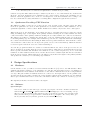
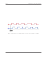
typically use optical gratings to produce two square-wave signals that are 90 degrees out of phase. This is
an example of a quadrature-encoded signal. The graph below shows how the two signals vary as the shaft
rotates in one direction.
Figure 1: Output for a 2 channel optical encoder rotating in one direction
1.2
Time Processor Unit (eTPU)
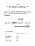
The time processor unit is described in the MPC5553 User’s Manual in Chapter 18:
The enhanced time processing unit (eTPU) is a new timing unit featured on the MPC5553/MPC5554
microcontroller that operates in parallel with the MPC5553/MPC5554 core (CPU). The eTPU
does the following:
• Executes programs independently from the host core
• Detects and precisely records timing of input events
• Generates complex output waveforms
EECS 461: Embedded Control Systems
1
Winter 2009
Lab 2
Quadrature Decoding using the eTPU
• Is controlled by the core without a requirement for real-time host processing
Software for specific eTPU functions may be written by the user, or, for common functions, obtained from
Freescale. Freescale Application Note AN2842 (on the course website) describes the quadrature decode
function. Read the application note, and look over Chapter 18 of the user’s manual before coming to the
lab. You can find the necessary information concerning TPU configuration registers in Section 18.4.
1.3
Quadrature Decoding eTPU Function
The MPC5553 eTPU operates in one of three modes: slow, normal or fast. We will operate the eTPU
in the slow quadrature decode mode. The quadrature decode function uses two eTPU channels to decode
quadrature signals into a 24-bit counter. Note: In this lab we will use only 16 bits of the count register.
When in slow mode, the quadrature decode function is able to determine direction by looking at both the
rising and falling edges of each signal. If the primary channel is leading the secondary channel, the 24-bit
counter increments. If the primary channel is trailing the secondary channel, the counter is decremented.
The function does this by comparing the current state of the two channels with the state before the most
recent rising/falling edge. For example, when channel B goes from low to high and channel A remains high,
the counter is incremented since B is trailing A. This creates 16 possible transitions: 4 increment the counter,
4 decrement the counter, and 8 are errors (see the prelab, below, for more information). When the function
receives a sequence that is an error, the counter is unchanged.
You can also program the function to switch to normal and fast modes, based on the speed of the encoder
wheel. Normal mode applies when the speed is greater than a defined slow-to-normal threshold, but less
than a specified normal-to-fast threshold. In normal mode, the counter is updated by one for each valid
transition on either channel as in slow mode, but the direction is not calculated (the last direction calculated
in the slow mode is kept). When in fast mode, the function only monitors the signal on the primary channel,
and updates the counter by 4 on each rising edge transition.
2
2.1
Design Specifications
Hardware
On the interface board, you will see a header bank labeled TPU A [0..7] next to the DIP switches. These
channels can interface with up to four quadrature encoders (the chip itself supports up to 32 channels per
TPU; 8 channels are made available on the interface board, and two channels are needed for each quadrature
encoder). The pins for TPU A channels 0 and 1 are connected to the haptic wheel over the parallel cable.
You may use the header bank to measure the voltage signals coming from the quadrature encoder channels.
Test loops for channels 0 and 1 are located next to the header bank for easy connection of oscilloscope probes.
The digital I/O interface from Lab 1 will be used again.
2.2
Software
fqd.h and fqd.c
You need to make a C file called fqd.c from the fqd template.c file that contains four functions
named init FQD, ReadFQD pc, updateCounter and updateAngle (see “Notes on Casting” below).
The prototypes and details of these functions can be found in the fqd.h file. It is very important
that you follow these prototypes and the comments in the fqd template.c file closely. Place fqd.c
file in your lib/ directory and the fqd.h file in your include/ directory.
EECS 461: Embedded Control Systems
2
Winter 2009
Lab 2
Quadrature Decoding using the eTPU
Makefile
To simplify the compilation process, a makefile has been provided to you. Note that for the
makefile to work, you need to make sure that all of your files are in their proper directories, as
specified in the lab handouts. The gmake command must be run from your lab2/ directory.
Freescale header files used in this lab: etpu qd.h, etpu set.h.
2.3
Notes on Casting
In previous years students have sometimes observed a peculiar problem in which their updateCounter
function failed to update the position correctly. The specific behavior observed was that the top 8 bits of
the bar LEDs would alternate between being all on (0xFFXX) or all off (0x00XX). In the following exercise,
we will see that this problem is due to the subtleties involved in typecasting correctly.
The following code does not work correctly. NEW TOTAL and LAST TOTAL are int32 ts and CURR FQDPC
and PREV FQDPC are uint16 ts:
int32_t updateCounter()
{ /* setup */
return (LAST_TOTAL + (CURR_FQDPC - PREV_FQDPC));
}
This code will work:
int32_t updateCounter()
{ /* setup */
return (LAST_TOTAL + (int16_t)(CURR_FQDPC - PREV_FQDPC));
}
Note the difference between these two examples: they are identical except that the quantity (CURR FQDPC
- PREV FQDPC), of type uint16 t, is cast to an int16 t before being added to total. This is needed so that
the quantity is sign-extended when it is turned into a long (so as to be added with total). For more information
on sign extension, read section 4.2 of Computer Organization and Design: The Hardware/Sortware Interface.
By John L. Hennessy and David A. Patterson. For more information of casting, read section 2.7 of The C
Programming Language, by Brian W. Kernighan and Dennis M. Ritchie.
To make this clearer, here is an example:
LAST TOTAL = 0x00007FFF CURR FQDPC = 0xFFFF PREV FQDPC = 0x0000
CURR FQDPC - PREV FQDPC yields the unsigned quantity 0xFFFF, which when changed to an int32 t
(a signed value) becomes 0x0000FFFF. This is not the desired result. It now represents a large positive
number, instead of -1. If the quantity CURR FQDPC - PREV FQDPC is first cast as an int16 t, as in
the second example, then when it is converted to an int32 t it is sign-extended to 0xFFFFFFFF, or -1, the
desired value. Note that the quantity (CURR FQDPC - PREV FQDPC) can be changed to (PREV FQDPC
- CURR FQDPC). This will only change the directions for turning the wheel to increment or decrement the
counter.
Note that LAST TOTAL and PREV FQDPC will have to be static variables in order to maintain their
values between calls to updateCounter. Note also that PREV FQDPC must have the same initial
value as the position count register in fqd.c or there will be an initial offset in the count.
3
Pre-Lab Assignment
Pre-lab questions must be done individually and handed in at the start of your lab section. You must also,
with your partner, design an initial version of your software before you come to your lab section. Your
EECS 461: Embedded Control Systems
3
Winter 2009
Lab 2
Quadrature Decoding using the eTPU
software does not need to be completely debugged, but obviously more debugging before coming to lab means
less time you will spend in the lab.
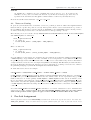
1. Fill in the truth table in Table 1 for quadrature decoding. Xi−1 and Yi−1 refer to the previous state
while Xi and Yi refer to the current state. The valid actions are increment, decrement, and error. A
few have already been done for you.
2. A 32 pulse encoder is an encoder that provides a square wave signal with 32 periods (or 64 edges,
rising and falling) on each channel per revolution. What is the resolution (smallest measurable
amount) in degrees of the quadrature decode function operating in slow mode with a 32
pulse encoder? With a 512 pulse encoder?
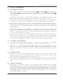
3.
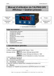
a. On Figure 2, draw lines where the quadrature decode function would update the
counter and label each line with the value the counter would hold. Assume the function
is operating in slow mode.
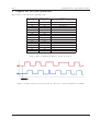
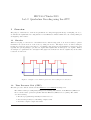
b. Repeat Part (a) for Figure 3, but assume that the function is running in fast mode now.
4. Briefly (not more than 60 words) summarize the differences between slow, normal, and fast
decoding.
5. The eTPU is a separate co-processor that operates in parallel with the 5553 core. What is the
advantage of having a separate processor?
6. Complete fqd.c.
EECS 461: Embedded Control Systems
4
Winter 2009
Lab 2
4
Quadrature Decoding using the eTPU
In-Lab Assignment
4.1
Reading the Counter
1. Write a simple C program called lab2.c that uses the init FQD and ReadFQD pc functions from fqd.c.
Create a uint16 t variable, counter, in your program and store the values returned by ReadFQD pc
in this variable. You will be able to examine the count value of the decoder by looking at this variable
when debugging.
2. Compile and debug your lab2.c program using the makefile by entering gmake at an DOS prompt.
Make sure that all your files are in their respective directories, or the compilation will fail.
3. Power up the board and use the P&E Debugger to download the lab2.elf file to the board. Make sure
you have the encoder connected to the interface board correctly; ask the GSI if you are unsure.
4. In the debugger, add the variable counter to the Variables Window. Right click in the Variables
Window and select Add Variable, then type the variable name counter into the menu. Display the
value in Decimal, and use the Default data type. Click OK and you should now see counter in the
Variables Window.
5. Run the lab2.c program by clicking the High Level Go button in the debugger. Move the wheel of the
haptic device slightly. Then, stop running lab2.c by clicking the ‘Stop’ button in the debugger, which
is shown as a black square. The value of counter in the Variables Window should have changed. If
not, correct the problem before proceeding.
6. Reset the target by clicking on the ‘Reset’ lightning bolt button in the debugger. You may have to
press the button twice, until you see code run by in the Status Window and the Source Window is
cleared. Download and run lab2.elf again and turn the wheel of the haptic device one full revolution.
How much does the FQD function increment during one full revolution of the haptic wheel?
4.2
Overflow and Underflow
7. Use your knowledge from the Digital I/O Lab to output the value of posCount to the 16 LEDs.
Recompile your code using the same command as above. Download and run your code.
8. With your new code running, turn the wheel until the LED counter shows 0x8000. This is the center
position for the counter. Now, turn the wheel until the LED counter either underflows or overflows.
How many revolutions of the wheel does it take to overflow a 16-bit register starting at this center
value?
4.3
Faulty Casting
9. Modify your code so that you use your updateCounter function to keep track of the position count.
Output the middle 16 bits of your position counter to the LEDs. You can do this by using a bitwise
shift. Verify that your updateCounter function works correctly.
10. Repeat step 9, but modify updateCounter to use the faulty casting method from the ‘Notes on Casting’
section of this lab. Verify that there is in fact a problem with this code and show that problem to the
GSI.
4.4
Angle Calculation
11. Write a simple C program called lab2angle.c that outputs how much the haptic wheel turned counterclockwise, in degrees, to the LEDs by using the updateAngle function in fqd.c. Note that, similar
to what you did in updateCounter, you will need a static float in updateAngle to remember the
current angle. Do not call the function updateCounter from updateAngle. Compile your program by
entering gmake angle at an DOS prompt. Download the lab2angle.elf file to the board and demonstrate the functionality to the GSI.
EECS 461: Embedded Control Systems
5
Winter 2009
Lab 2
Quadrature Decoding using the eTPU
12. The post-lab asks questions about why the quadrature decode function may fail to correctly keep track
of position when the wheel is running at sufficiently high speeds. Before you leave the lab you might
want to discuss possible reasons for such a failure.
5
Post-Lab Assignment
1. What are two reasons that you think the quadrature decode function might stop working
at high speeds?
2. The MPC5553 eTPU can be programmed to switch automatically from slow to normal to fast mode
based on encoder speed. Why would the quadrature decode function work at a higher speed
when in fast mode? Hint: Read section 3.1 of AN2842 concerning how fast modes work.
3. Using the information about the encoder wheel given to you in fqd.c, what type of encoder are we
using in the haptic wheel? (e.g. 32 pulse, 256 pulse, etc.)
4. We now analyze situations for which the QD function may fail to correctly update the position count.
a. The system clock for our setup is 40MHz. Given that we are running the QD function in slow
mode, determine the maximum rate the haptic wheel can reach (revolutions/sec)
before the eTPU fails. See section 3.7 in Application Note AN2842 for eTPU performance.
b. Assume that the haptic wheel is running at the maximum speed allowed by the QD function (i.e.
at the speed computed in part a). What is the slowest possible periodic rate that the
the CPU can read the TPU position counter register while still knowing whether the
counter value is increasing or decreasing? You may assume that the wheel will be spinning
at this maximum rate in one direction. Calculate this rate based on both a 16-bit (what we used)
and 24-bit (what is available in the hardware) position counter size.
c. Relate that periodic rate to the number of processor cycles that can be executed
between checks.
5. Include well-documented copies of your fqd.c, lab2.c and lab2angle.c files.
If you have comments that you feel would help improve the clarity or direction of this assignment, please
include them following your postlab solutions.
EECS 461: Embedded Control Systems
6
Winter 2009
Lab 2
6
Quadrature Decoding using the eTPU
Figures for Pre-Lab Questions
These may be collected at the beginning of lab.
Previous State
(Xi−1 ,Yi−1 )
00
00
00
00
01
01
01
01
10
10
10
10
11
11
11
11
Current State
(Xi ,Yi )
00
01
10
11
00
01
10
11
00
01
10
11
00
01
10
11
Action
Error, Increment, or Decrement
Decrement
Increment
Error
Table 1: Encoder Transition Table for pre-lab problem 1.
Figure 2: Sample output for pre-lab problem 3a. The 16-bit counter is initialized to 0x0000.
EECS 461: Embedded Control Systems
7
Winter 2009
Lab 2
Quadrature Decoding using the eTPU
Figure 3: Sample output for pre-lab problem 3b. The 16-bit counter is initialized to 0x0000.
EECS 461: Embedded Control Systems
8
Winter 2009