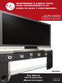
1
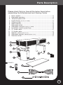
ENTERTAINMENT & GAMING CENTER
CENTRE DIVERTISSEMENTS ET JEU
CENTRO DE JUEGO Y ENTRETENIMIENTO
save These Instructions
Conserver ces instructionS
guarde estas instrucciones
GHP50BL
REV02
User Manual
Livre D’Instruction
Manual de Usuario
TV Not Included
TV Non Incluse
TV No Incluida
Introduction / Index
Introduction
Thank you for purchasing our product. Please read the
instructions in this manual carefully. Following and keeping
these instructions will enable you to obtain optimal
performance and listening enjoyment from this product.
Index
Parts Description........................................................ Page 1
Grounding Instructions............................................... Page 2
Assembly Instructions................................................ Page 2
Options....................................................................... Page 5
Trouble Shooting ....................................................... Page 6
Rear Panel Controls .................................................. Page 8
Controls ..................................................................... Page 9
Specifications............................................................. Page 10
Safety Warnings ........................................................ Page 11
Parts Description
Please check that you have all the below items before
assembling the Entertainment and Gaming Center
1.
2.
3.
4.
5.
6.
7.
8.
9.
10.
11.
12.
13.
14.
Main console.................................................................................x1
Subwoofer speakers......................................................................x2
Tempered glass shelf.....................................................................x1
Digital display (Factory Installed).........................................................x1
Cleaning cloth................................................................................x1
Shelf brackets................................................................................x4
Subwoofer outlet...........................................................................x2
Subwoofer contacts (Factory Installed)...............................................x2
Installation mounting openings.....................................................x3
5.1 Audio cable..............................................................................x1
2.0 Audio cable..............................................................................x1
Speaker covers (Black mesh)............................................................x6
Subwoofer speaker covers (Black mesh). .........................................x2
Remote control..............................................................................x1
1
4
12
8
9
2
6
13
5
7
Figure 1
3
14
10
11
1
Grounding and Assembly Instructions
Warning: Improper use of the grounding plug can result in a risk
of electric shock causing serious injury, even death.
This electronic device must be grounded. In the event of an
electrical short circuit, grounding reduces the risk of electric
shock by providing an escape wire for electric current.
This electronic device is equipped with a power cord having a
grounding wire with a grounding plug. The plug must be plugged
into an outlet that is properly grounded. Consult a qualified
electrician if the grounding instructions are not completely
understood, or if doubt exists as to whether the electronic device
is properly grounded. If the wall outlet is a standard 2 prong wall
outlet, it is your personal responsibility and obligation to have it
replaced with a properly grounded 3-prong wall outlet.
Do not under any circumstances cut or remove the third (ground)
prong from the power cord.
Do not use an adapter plug with this electronic device.
Do not use an extension cord with this electronic device. If the
power cord is too short, have a qualified electrician install an
outlet near the electronic device.
Do not attempt to operate this electronic device if it has a
damaged power cord or plug.
Assembly Instructions
Please retain all original packaging materials for future use in the
event the Entertainment and Gaming Center requires any of the
following: Servicing or Replacement
1. Place the left and right subwoofer speakers on the floor near to the location you will be installing your Entertainment and Gaming Center. The speakers need to face outward.
Ensure you are also close to a power outlet. Leave sufficient
room between the rear of the Entertainment & Gaming Center
and any adjacent walls to accommodate easy installation of
your audio/video equipment later on.
2
Assembly Instructions
Position the subwoofer speakers approximately 30” (76cm)
apart with the speakers facing outward. With the help of
another person carefully lift and position the main console
on top of the subwoofer speakers making sure the connecting
pins located on the underside of the console are aligned with
the matching key-hole openings (slots) located on top of the
subwoofer speakers.
Lower the connecting pins into the key-hole openings and
carefully slide the console forward until it comes to a complete
stop. The main console should now be properly aligned with
the subwoofer speakers.
WARNING:
LIFTING HAZARD
Single person
lift could
cause injury.
use assistance when
moving or lifting.
WARNING: TO AVOID PERSONAL INJURY AND/
OR EQUIPMENT DAMAGE, NEVER ATTEMPT TO
LIFT THE FULLY ASSEMBLED ENTERTAINMENT
CENTER COMPLETELY OFF THE GROUND, AS THE
SUBWOOFER
SPEAKERS
MAY
BECOME
ACCIDENTALLY UNHOOKED AND FALL.
2. Carefully slide the glass shelf onto the 4 support pins located
on the inside of the subwoofer speakers making sure the
shelf is firmly positioned and level.
3. Remove the protective covers (usually grey) from the
speakers located on the main console. Keep these covers for
future use in the event the system has to be moved to another
location.
4. Optional: Assemble the 6 mesh speaker covers by lining up the pins on the main console with the holes on the speaker cover gently pressing them into place.
5. Make sure all audio/video equipment is “disconnected” before
connecting to the Entertainment & Gaming Center. Position
your DVD player on the glass shelf. Connect one end of the
6 pin audio surround sound cables (included) to the 5.1
channel outputs on the DVD player, (consult DVD manual) and
the other end to the 5.1 channel inputs on the Entertainment
and Gaming Center. If your DVD player does not have 5.1
channel outputs, simply connect one end of the twin audio
3
6
Assembly Instructions
cables (included) to the “AUDIO OUT” channels on the
DVD player and the other end to the 2.0 channel inputs on the
Entertainment and Gaming Center.
FUSE
T2AL 250V
T2AL 250V
ON
5a.
5.1 Input Channels
FL = Front Left
FR = Front Right
SL = Side Left
SR = Side Right
C = Center
W = Subwoofer
ON
OFF
FUSE
T2AL 250V
T2AL 250V
OFF
FUSE
T2AL 250V
DVD
T2AL 250V
ON
OFF
C
FL
SL
FR
SR
2.0
W
ON
5.1
ON
OFF
OFF
DVD
RCA to RCA
L
FL
SL
C
FR
SR
W
R
TV
FL
FR
SL
SR
DVD
2.0 Input Channels
L = Left
R = Right
GAME INPUT
GAME CONSOLE
C
RCA to RCA
L
W
FL
SL
FR
SR
TV
MP3
C
DVD
W
GAME INPUT
6. Connect the video cables (not included)
from the component video outputs on
your DVD player, (consult DVD manual)
RCA to RCA
to the component video inputs on your TV
set (consult TV manual). RCA
Check
that all of
to RCA
your connections are secure
FL
DVD
GAME CONSOLE
C
SL
FEMALE END
FL
FR
DVD
R
MP3 INPUT
SR
SL
MALE END
FR
SR
MP3
MP3 INPUT
C
L
W
RCA to RCA
R
TV
W
FEMALE END
MALE END
L
GAME INPUT
GAME CONSOLE
R
L
TV
MP3
MP3 INPUT
RCA to RCA
L
R
R
TV
TV
7. Plug in all of your audio/video equipment, you are now ready
GAME CONSOLE
to turn the system on. Carefully slide the Entertainment
and
GAME CONSOLE
Gaming Center to the wall, (DO NOT LIFT) leaving a clearance
MP3
of approximately 6” (15cm) behind the
systems.MP3This spacing
is to allow for proper ventilation of all components.
FEMALE END
MALE END
GAME INPUT
GAME INPUT
GAME INPUT
GAME CONSOLE
MP3 INPUT
MP3
MP3 INPUT
MP3 INPUT
8. The power (on/off) switch for the Entertainment and Gaming
Center is located at the middle front edge on the underside of
the main console.
FUSE
FEMALE END
MALE END
T2AL 250V
FEMALE END
MALE
FEMALE
ENDEND
ON
OFF
4
MALE END
Options
Gaming Console
TV
GAME CONSOLE
If you are not utilizing the 2.0 channel inputs on your Entertainment and Gaming Center, you can connect a gaming console to
these channel inputs for enhanced sound quality, using the twin
audio cables (included).
Hand Held Gaming Systems
MP3
You can also connect hand held gaming
systems to the Front Control Panel for
enhanced sound quality, using the input
GAME
channel marked “Game In” on the left side
of the Front Control Panel.
MP3 Players
For ease, convenience and enhanced
sound quality, you can connectMP3
your
MP3 player to the input channel marked
“MP3
MALE
ENDIn” located on the right side of the
Front Control Panel. You can also connect
your MP3 player to the 2.0 inputs (if not
being utilized), located at the back of the
Entertainment and Gaming Center, for 2.0
sound quality.
CONSOLE
Game In on
Front Panel
MP3 In on
Front Panel
NOTE: This will require a special audio cable inclusive of a 3.5mm mini RCA jack
at one end (MP3 connection) and 2 regular stereo RCA jacks at the other end
(Entertainment and Gaming Center connection) available at most electronic retail
stores
MALE END
5
Trouble Shooting
6
No Power
Check the power switch is turned to the ON position
Check the power cord is installed securely in the main console
Check the power cord is installed securely in the wall outlet
Check the wall outlet is active (breaker may be tripped/re-set)
Check the internal fuse located at the back of the main console, replace if necessary (use fuse specification F2AL250VP only)
Remote Control
Not working
Check the condition of the batteries (if weak
replace)
Make sure the path between the remote control and the (main console) infra-red receiver is not obstructed.
No Sound
From DVD
Check that you have connected the DVD player
correctly to the Entertainment & Gaming Center
Check that the DVD player is operational (outputting sound)
Check the DVD’s owner’s manual for correct 5.1 outputs
Re-press the 5.1 channel button on the remote control
Check batteries are installed correctly
(+/- polarity)
The LCD viewing screen must display 5.1 mode. If 2.0 mode is displayed in the viewing screen, 5.1 sound will not be heard.
Trouble Shooting
Likewise, if the 5.1 mode is visible in the LCD viewing screen, 2.0 sound will not be heard
Re-press the 2.0 channel button on the remote control
No Sound From
2.0 Stereo Inputs
If you are utilizing either of the Front Control
Panel channel inputs (MP3-In/GAME-In), these
connecting cable(s) must be disconnected to
hear 2.0 sound, however, this does not apply to
5.1 sound listening
Check the playing device is operational (outputting sound)
No sound from
the MP3 input
Check the owner’s manual (electronic
components) if you need to change output
settings
Check that you have connected the MP3 output correctly
Check the MP3 is operational (outputting sound)
Check your MP3 owner’s manual if you need to change the output settings
Re-press the 2.0 channel on the remote control
Check that you have connected the stereo (2.0)
output channels correctly to the Gaming and
Entertainment Center
7
Rear Panel Controls
1.
2.
3.
4.
5.
6.
FL
SL
C
FR
SR
W
Power On/Off (Located at front of unit)
Fuse (Use type F2AL250VP ONLY)
Power cable
Input option
5.1ch Input
2.0 ch Input
L
RCA to RCA
R
FUSE
T2AL 250V
Figure A
GAME INPUT
2
GAM
FUSE
FUSE
FUSE
T2AL 250V
T2AL 250V
T2AL 250V
FUSE
T2AL 250V
5
MP3 INPUT
ON
FUSE
MP3
4
T2AL 250V
OFF
1
3
ON
OFF
OFF
OFF
FEMALE END
MALE END
OFF
ON
Figure B
OFF
DVD
FL
FR
FL
FR
FL
C
SL
SL
FL
SR
SL
SR
SL
C
W
C
SR
SR
W
W
FL
FR
SL
SR
C
W
FR
SR
W
R
DVD
DVD
RCA to RCA
L
R
2.0 Audio Cables
(included)
RCA to RCA
R
R
L
TV
RCA
RCA to
to RCA
RCA
RCA to RCA
L
L
L
DVD
DVD
DVD
C
FR
FR
W
Figure C
5.1 Audio Cables
(included)
C
SL
FL
TV
TV
TV
R
TV
RCA to RCA
GAME INPUT
L
GAME CONSOLE
Figure D
R
GAME INPUT
TV
GAME
GAME INPUT
INPUT
GAME INPUT
GAME
GAME CONSOLE
CONSOLE
GAME CONSOLE
MP3
MP3 INPUT
GAME INPUT MP3
MP3 INPUT
INPUT
MP3 INPUT
Figure
MP3 E
INPUT
Game Console/MP3
2.0 Audio Cables
(not included)
FEMALE END
MP3 INPUT
FEMALE
8
6
ON
ON
ON
MP3
MP3
MP3 GAME
CONSOLE
MP3
MALE END
Game Console/MP3
Audio Cables
(not included)
FEMALE
FEMALE END
END
END
GAME CONSOLE
MALE END
MALE
MALE END
END
FEMALE END
MALE END
FEMALE END
MALE END
MP3
Controls
Digital Display Control
1
MUTE
5.1
2.0
STBY
2
MUTE
5.1
2.0
STBY
1.
2.
3.
4.
5.
6.
7.
8.
LCD screen
Receiver
(Remote Control)
Standby
(Power Button)
Volume down
Mode
Game input
Volume up
MP3 Input
1.
2.
3.
4.
5.
6.
7.
8.
9.
10.
11.
12.
13.
Power On/Off
Center up
Surround down
Center down
2.0 ch. option
Volume up
Subwoofer down
Reset
Surround up
5.1 ch. option
Mute
Subwoofer up
Volume down
STBY
3
4
VOL-
5
STBY
7
VOL+
8
6
GAME INPUT
VOL-
GAME INPUT
MODE
MP3 INPUT
VOL+
MODE
MP3 INPUT
Remote Control
1
2
3
9
5
10
4
11
6
12
7
13
8
9
Specifications
1. Output power
A - Center Speakers
B - Front Speakers
C - Side Speakers
D - Subwoofer Speakers
2. Frequency Response
3. Power Requirement
18W x 2
13W x 2
13W x 4
30W x 2
25Hz-20KHz
120V-60Hz
C
1
C
C
B
A
2
D
10
3
A
C
B
Safety Warnings
Leave 6” (15cm) for ventilation.
6”
6”
6”
6”
Do not block any ventilation openings.
6”
Do not open or repair unit
6
yourself.” Refer servicing to
qualified personnel.
Do not position the unit near
water, and clean only with a dry
cloth provided.
Do not climb or stand on the unit.
Pull out the plug if smoke, a peculiar
smell or any strange noise comes out
of the unit. And unplug this apparatus
during lightning or when unused for
long periods of time.
11
Introduction/Index
Introduction
Merci d’avoir acheté notre produit. Veuillez lire attentivement
les instructions de ce manuel. Le fait d’observer et de
conserver ces instructions vous permettra d’optimiser les
performances de votre appareil et d’en profiter pleinement.
Index
Description des pièces............................................... Page 13
Instructions de mise à la terre.................................... Page 14
Instructions de montage............................................ Page 14
Options....................................................................... Page 17
Dépannage................................................................. Page 18
Panneau de commande arrière ................................. Page 20
Commandes............................................................... Page 21
Spécifications............................................................. Page 22
Consignes de sécurité................................................ Page 23
12